Investigation on the Corrosion Behavior of Lean Duplex Stainless Steel 2404 after Aging within the 650–850 °C Temperature Range


Abstract
1. Introduction
2. Materials and Methods
Electrochemical Measurements
3. Results
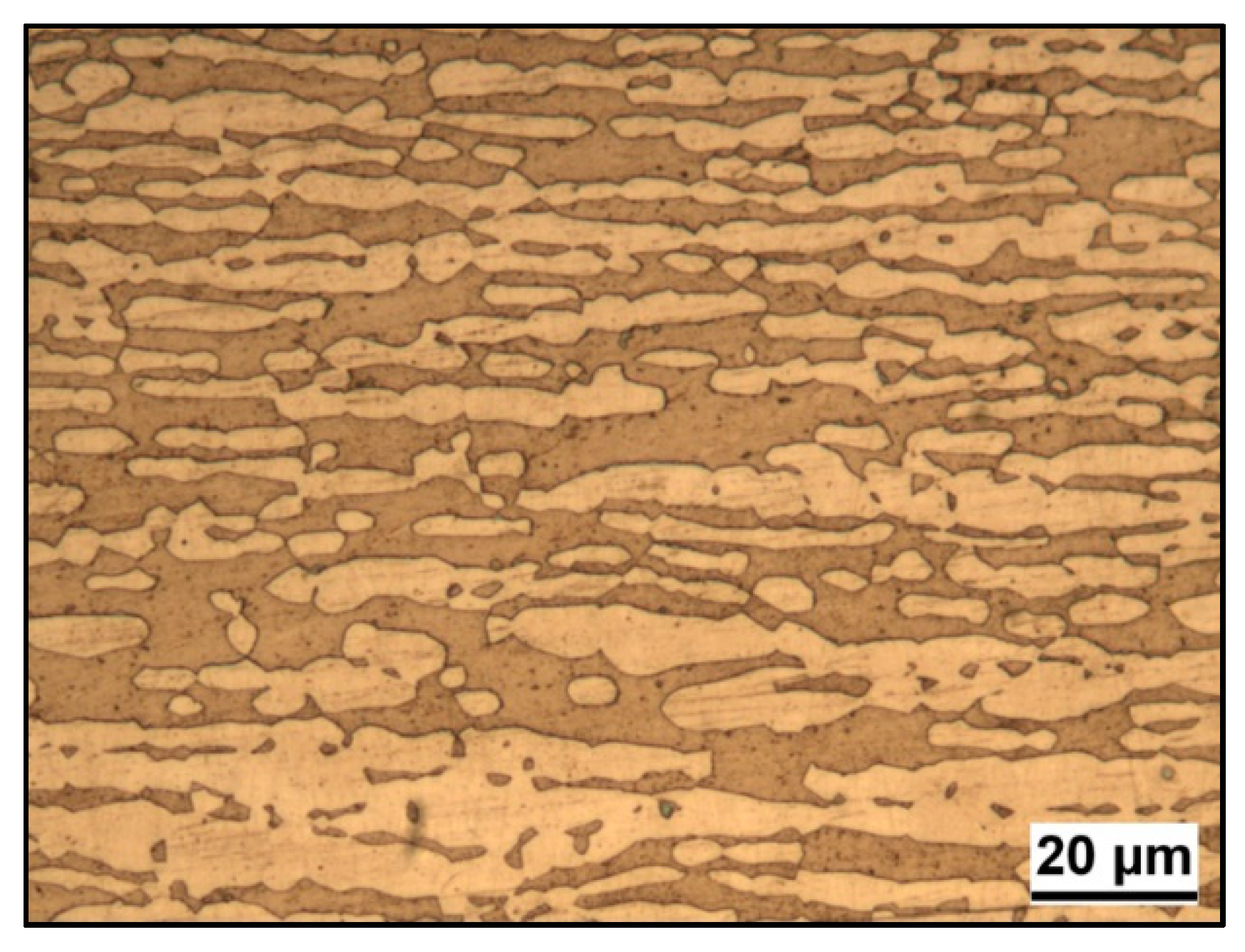
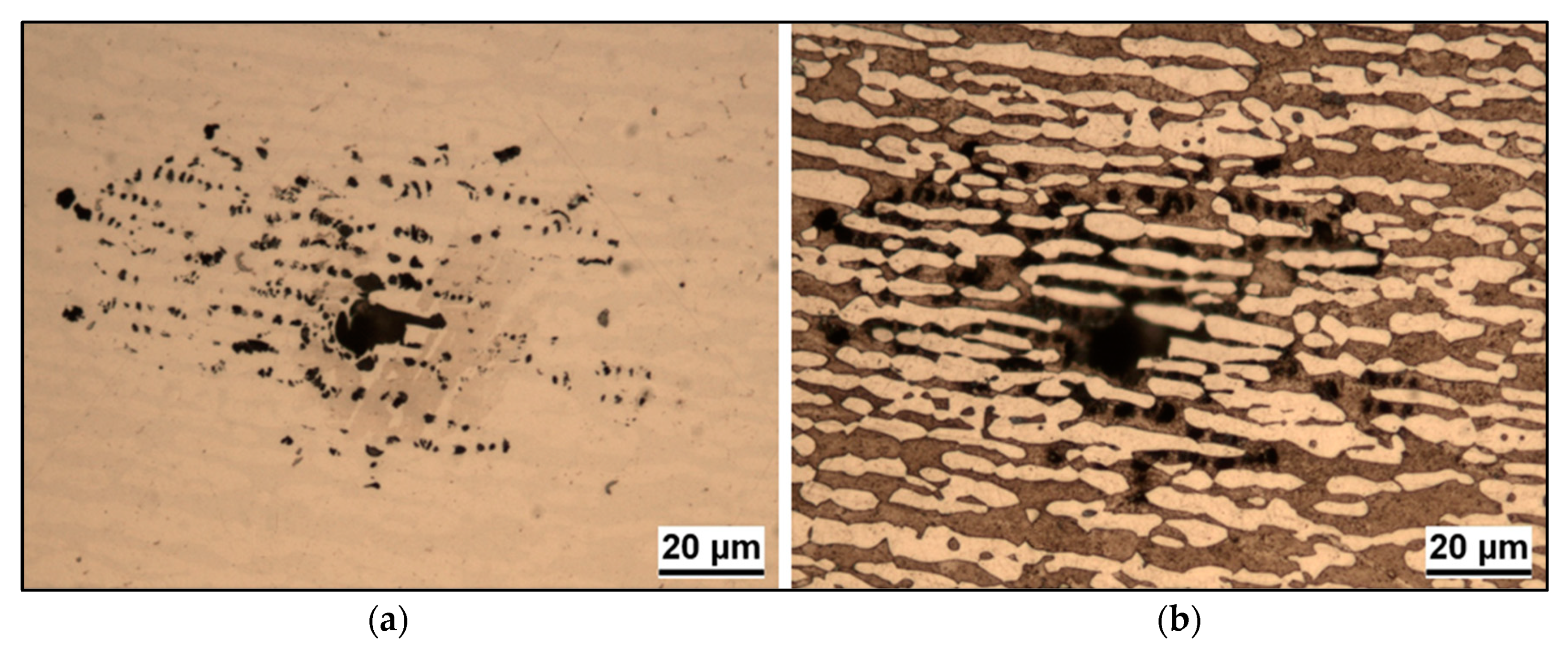
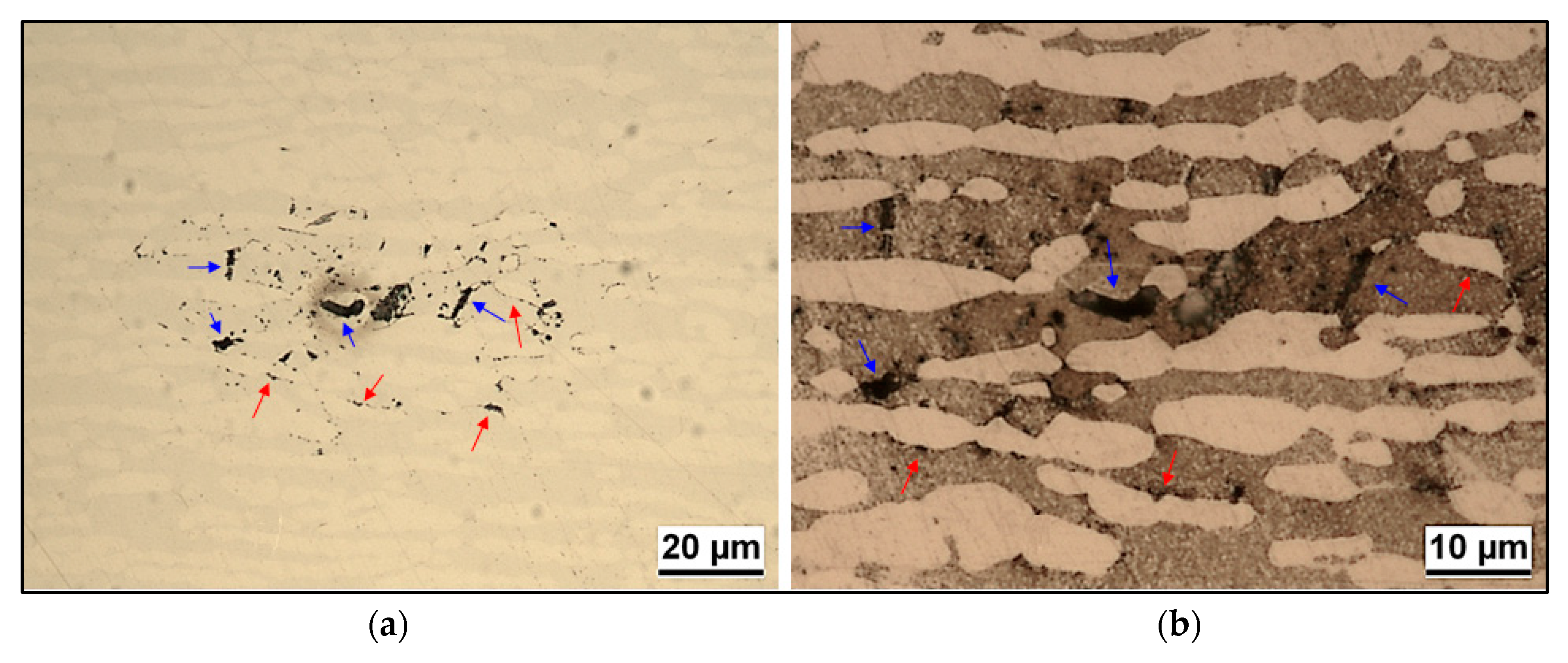
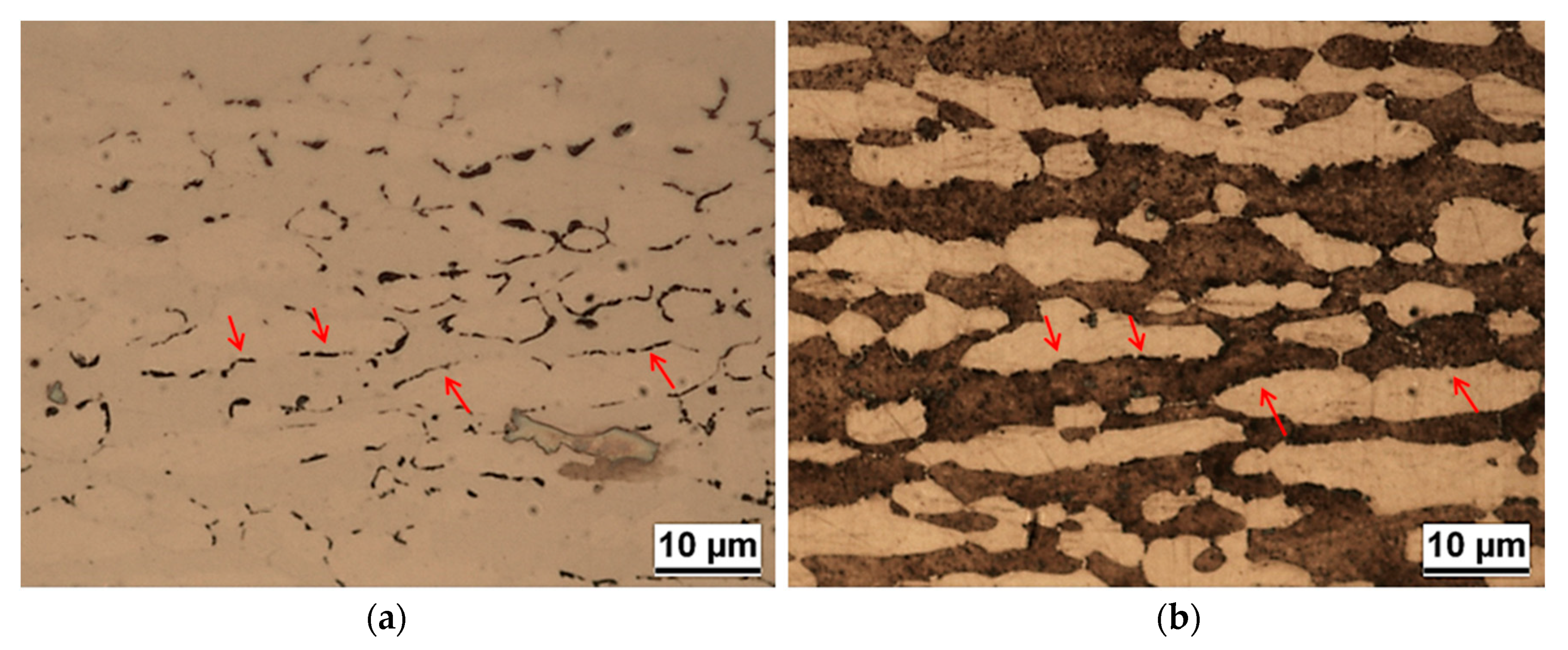
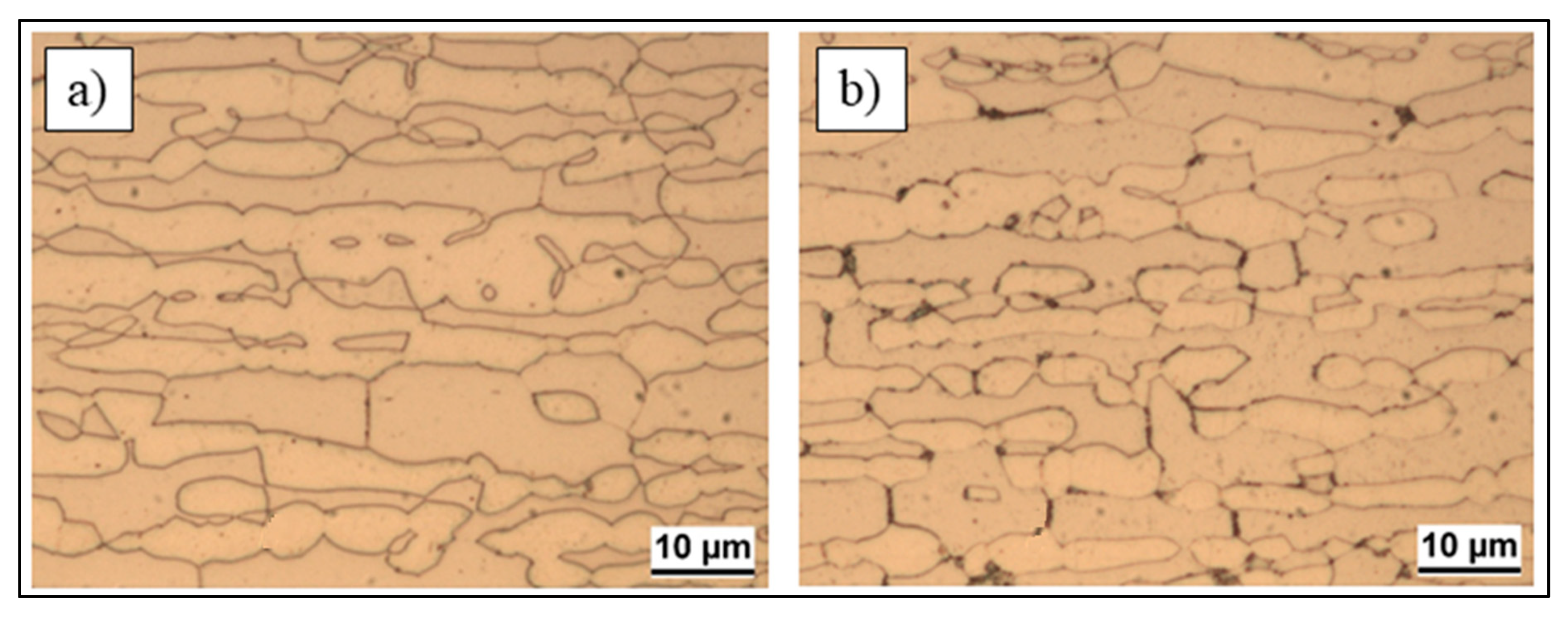
3.1. Microstructure
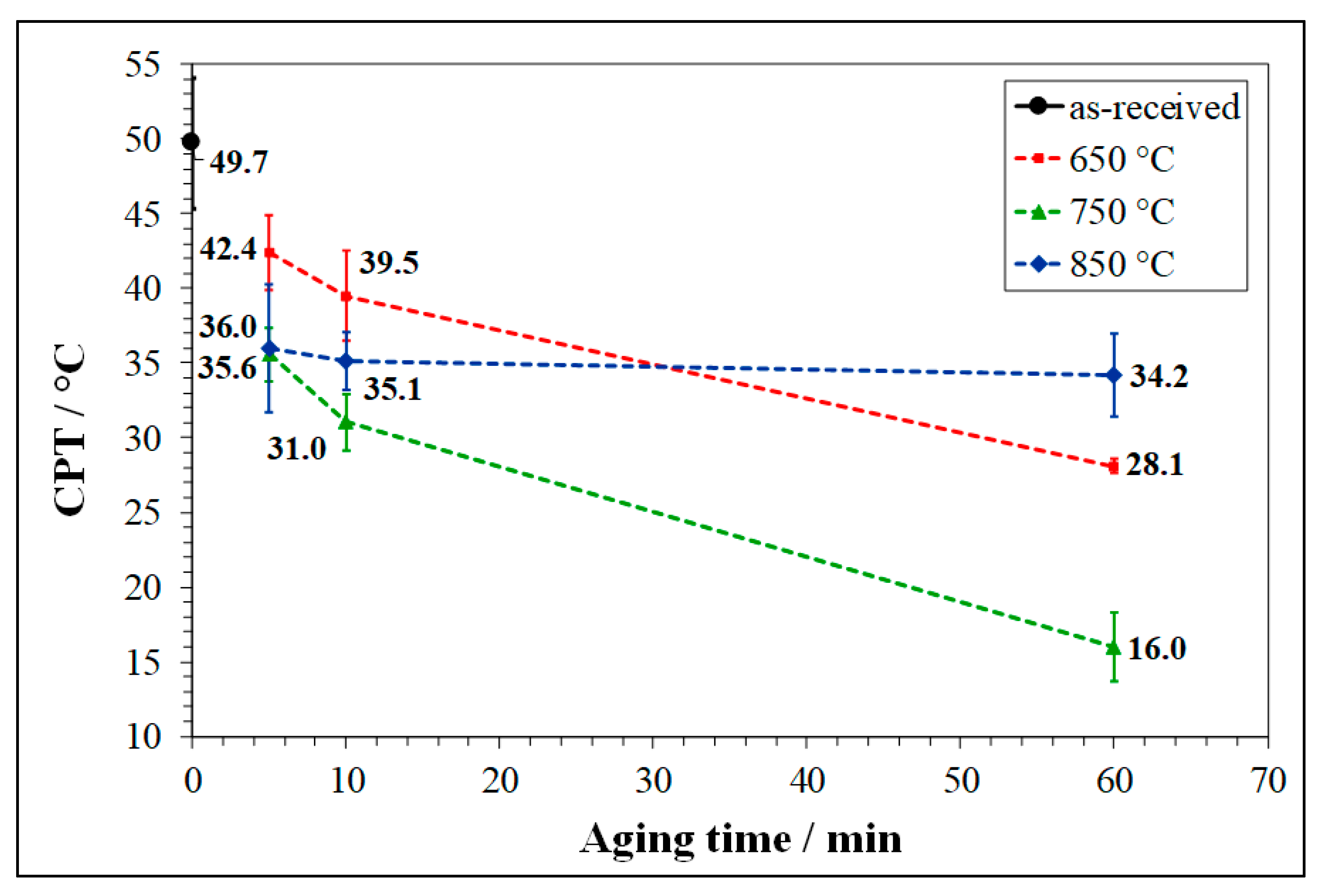
3.2. Critical Pitting Temperature (CPT) Test
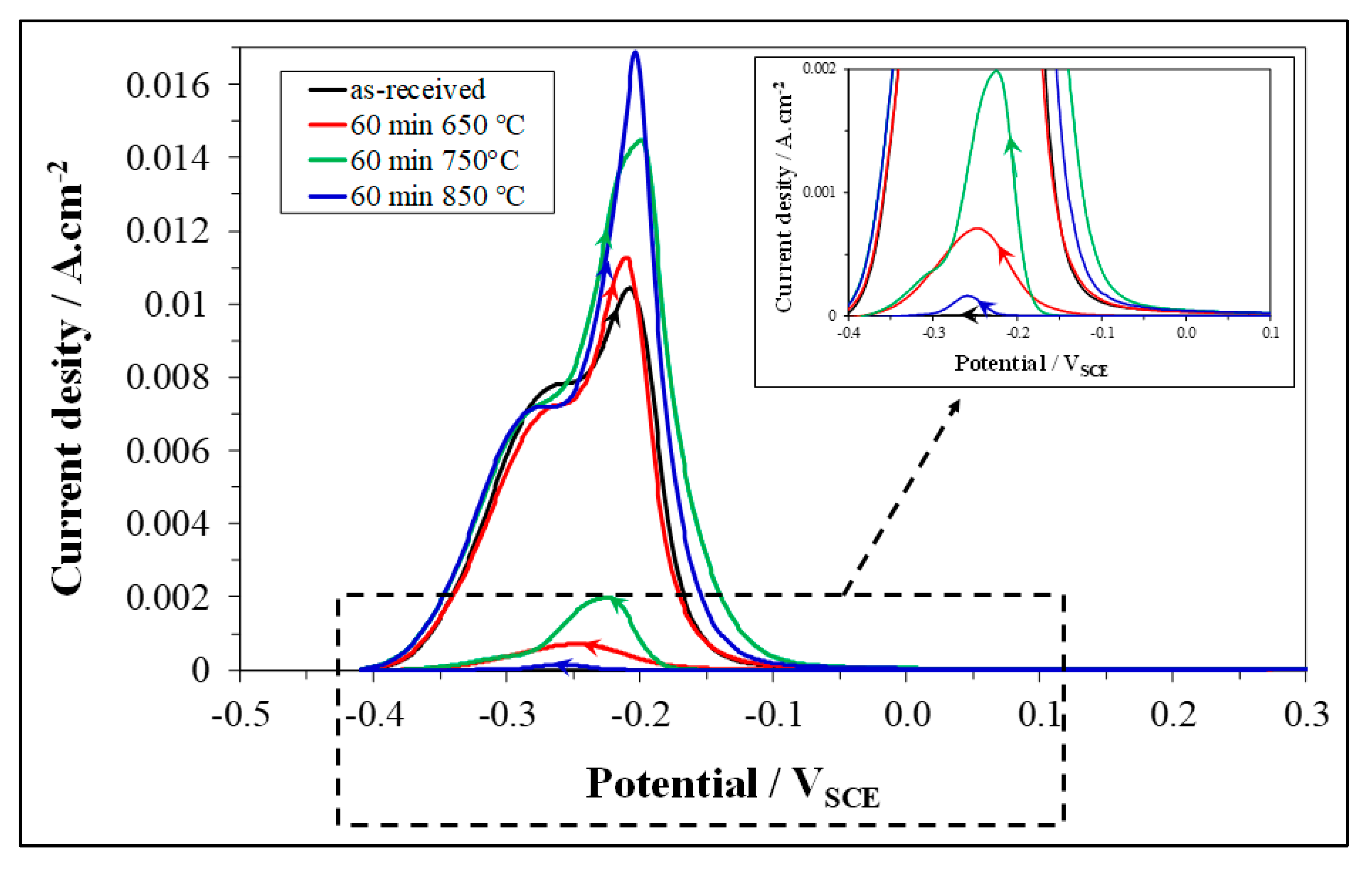
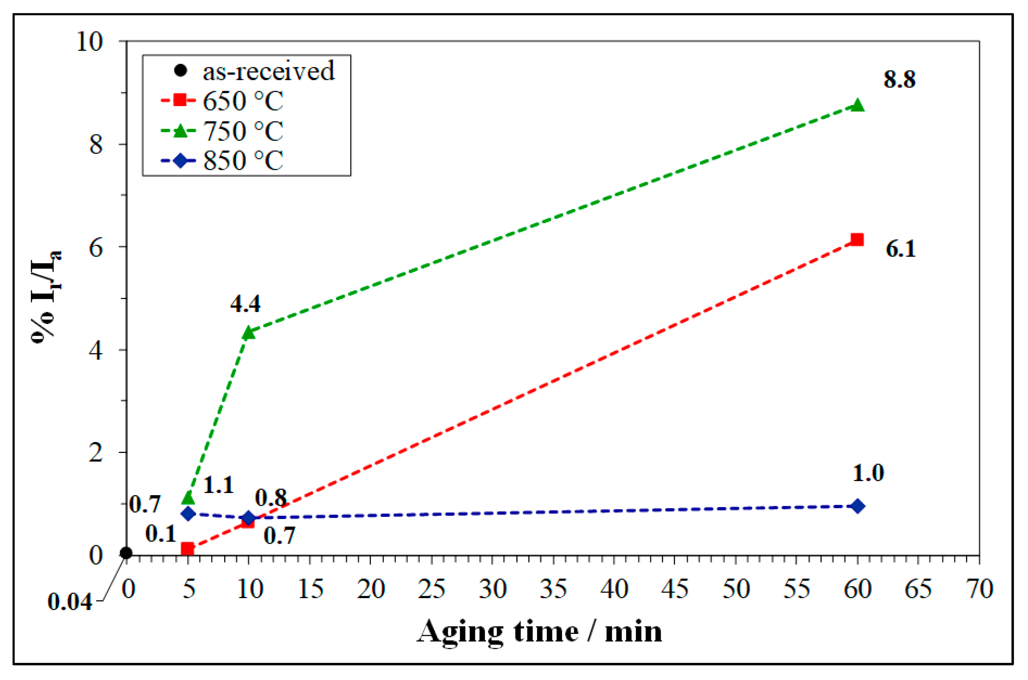
3.3. Double Loop Electrochemical Potentiokinetic Reactivation (DL-EPR) Test
4. Conclusions
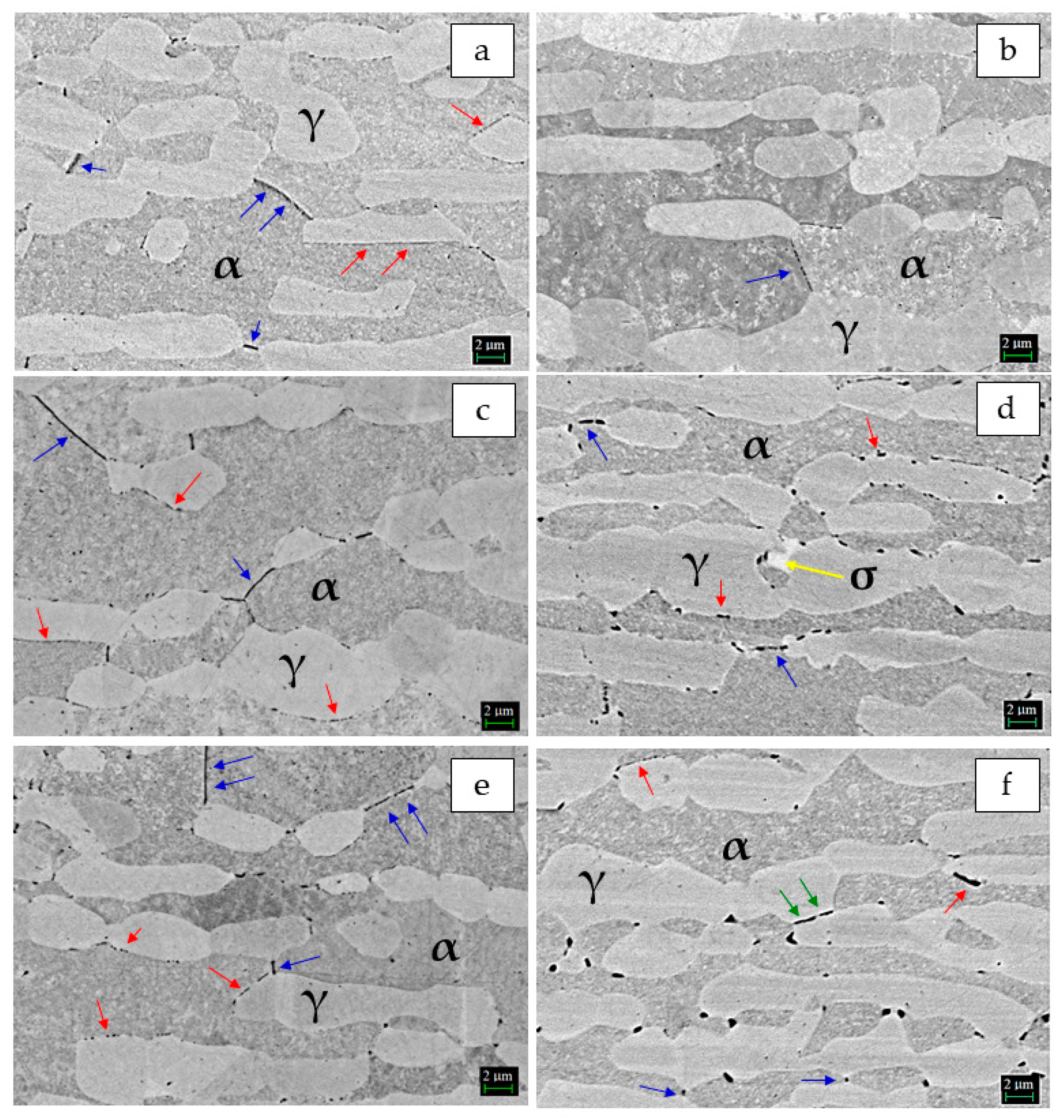
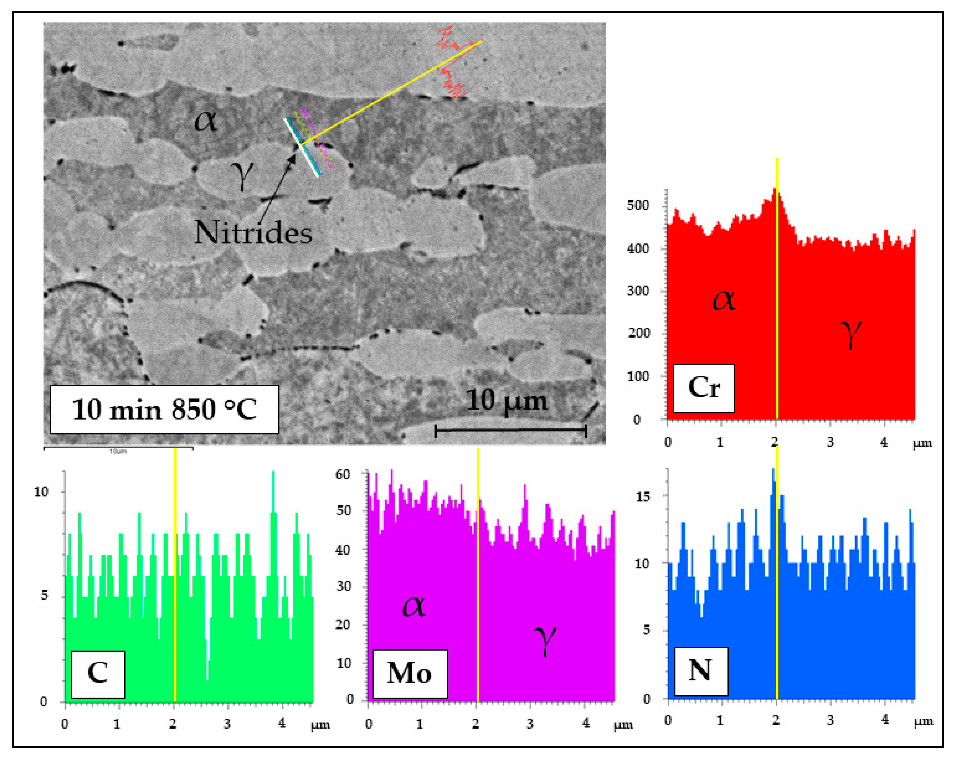
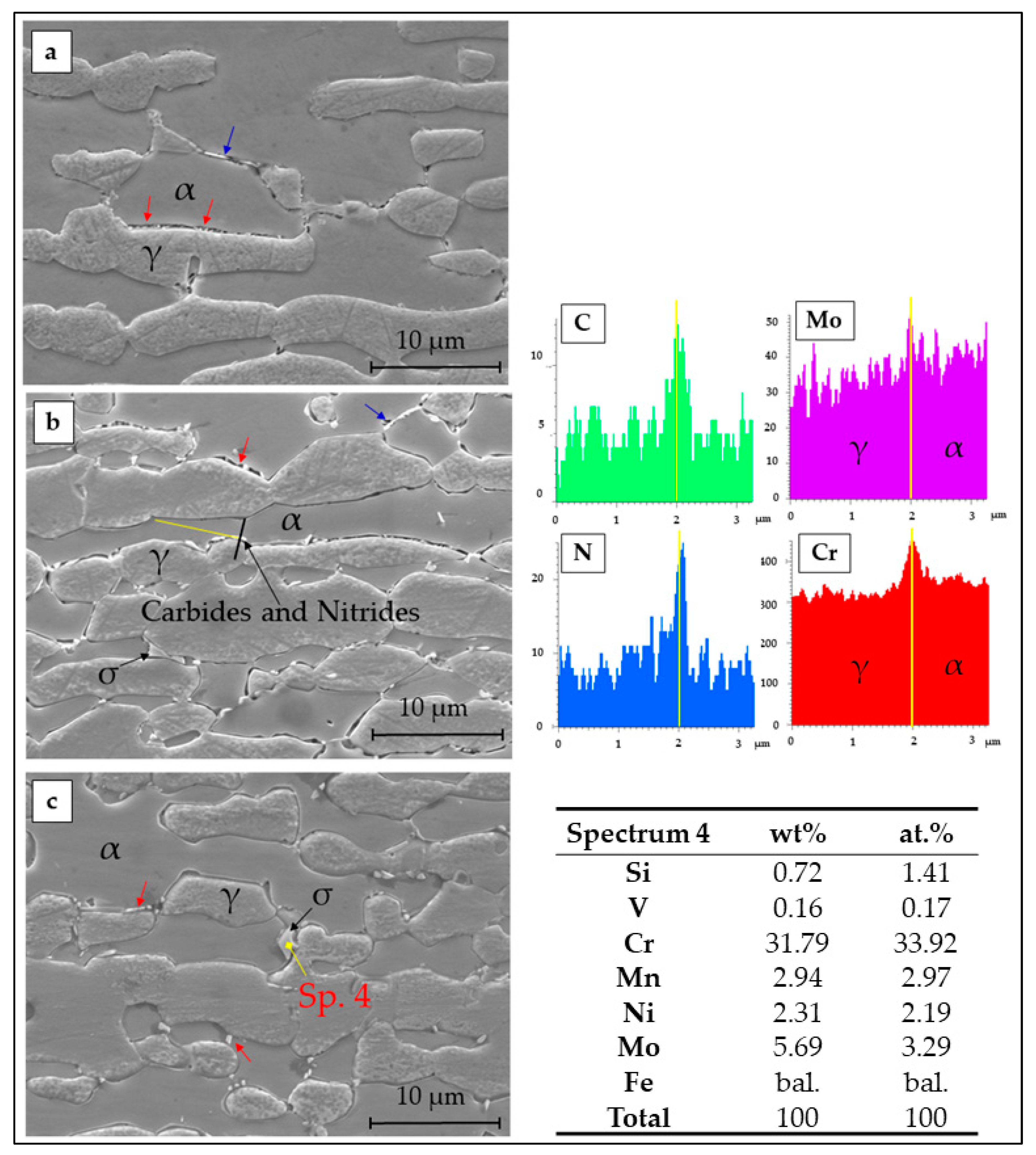
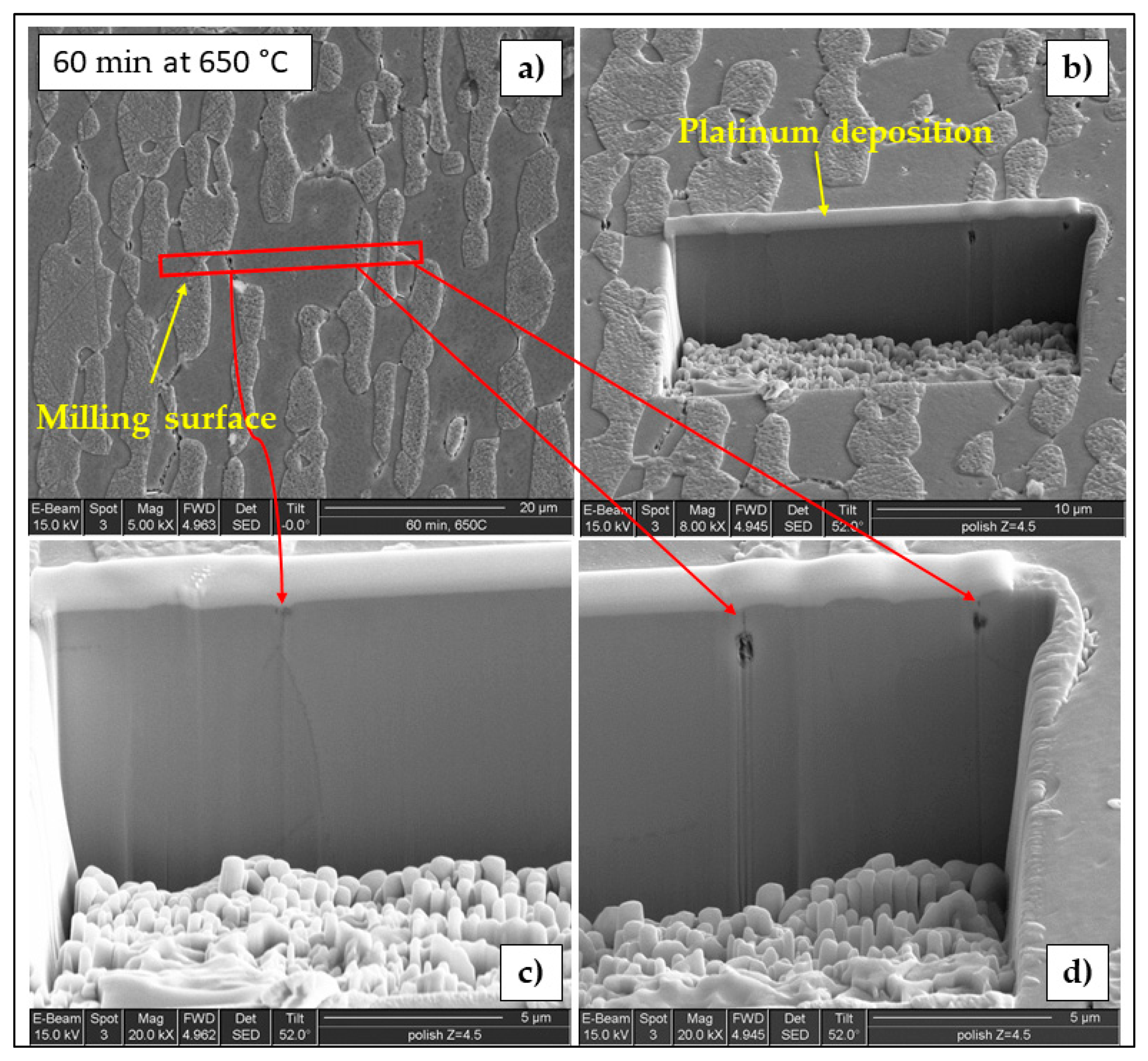
- The brief thermal aging performed in the 650–850 °C range on LDSS 2404 determined the formation of mainly chromium nitrides at grain boundaries.
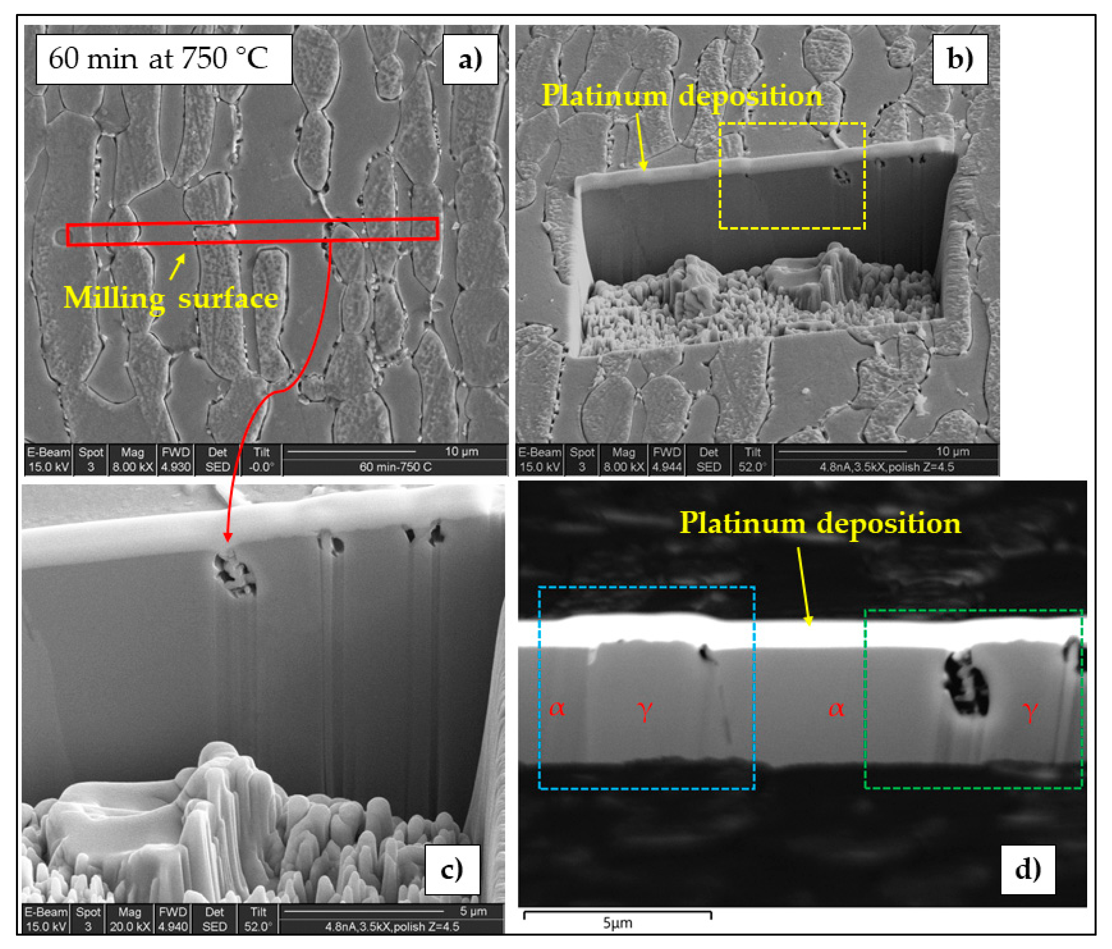
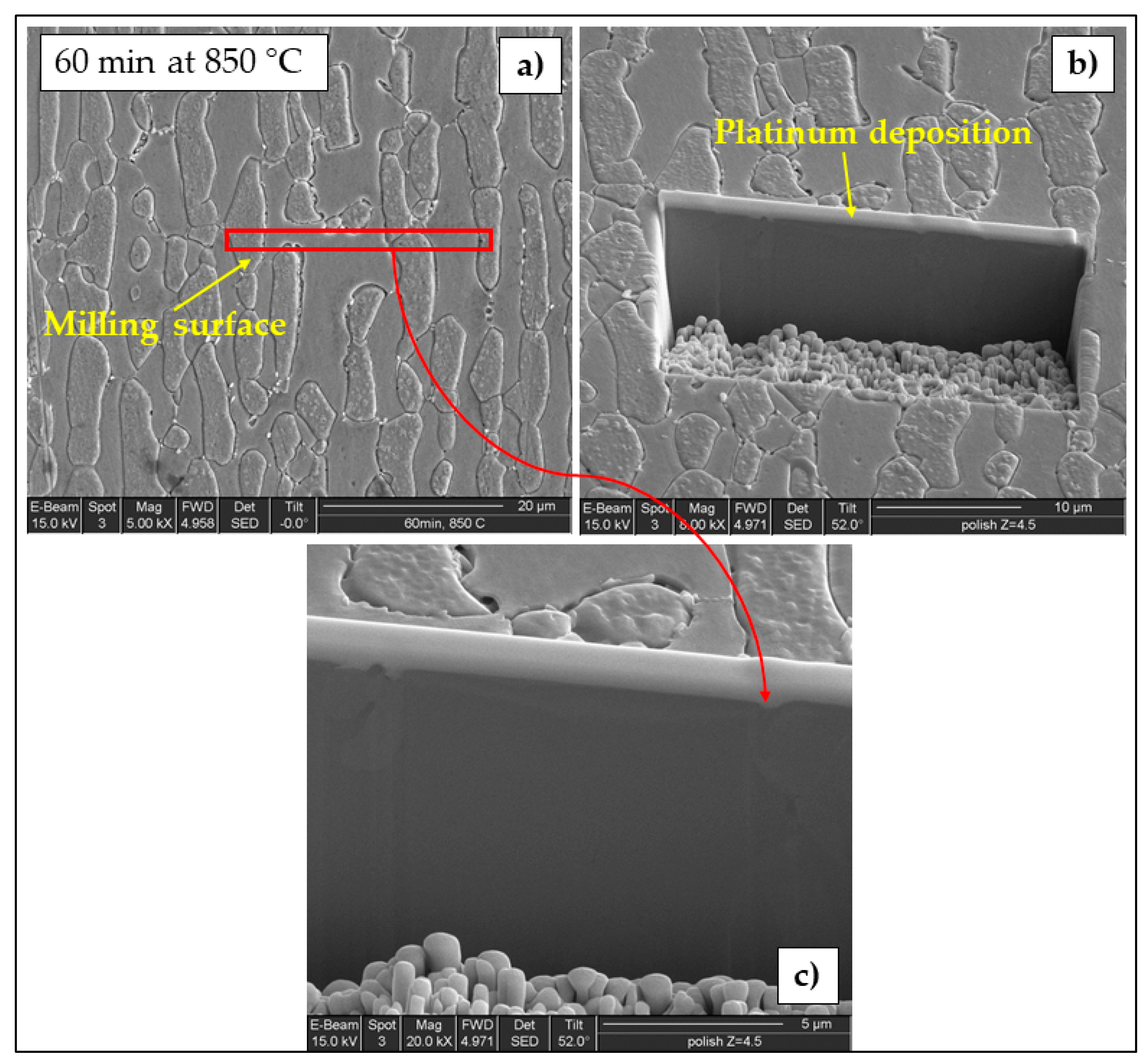
- Localization and distribution morphologies of these precipitates depended on thermal aging conditions. Aging at 650 °C or short aging times (5 min) at 750 °C caused nitride precipitation mainly at α/α grain boundaries because of fast diffusion in this phase. Aging at 850 °C or aging times from 10 to 60 min at 750 °C also allowed precipitation at the α/γ interface. Nitrides at γ/γ grain boundaries were observed rarely and only after long aging times (60 min) at 850 °C.
- At 650 and 750 °C, the susceptibility to pitting corrosion of LDSS 2404 increased by prolonging the aging time and was higher at 750°C. Instead, at 850 °C a partial recovery of pitting resistance was detected. The effects of thermal treatments on DOS to IGC were in good agreement.
- Pitting corrosion attack and IGC attack after DL-EPR were mainly localized at α/α grain boundaries (particularly at low aging temperatures and short aging times) or at α/γ interfaces (mainly at high aging temperatures and long aging times).
Author Contributions
Funding
Acknowledgments
Conflicts of Interest
References
- Olsson, J.; Snis, M. Duplex—A new generation of stainless steels for desalination plants. Desalination 2007, 205, 104–113. [Google Scholar] [CrossRef]
- Zhang, Z.; Zhao, H.; Zhang, H.; Yu, Z.; Hu, J.; He, L.; Li, J. Effect of isothermal aging on the pitting corrosion resistance of UNS S82441 duplex stainless steel based on electrochemical detection. Corros. Sci. 2015, 93, 120–125. [Google Scholar] [CrossRef]
- Silva, R.; Baroni, L.F.S.; Kugelmeier, C.L.; Silva, M.B.R.; Kuri, S.E.; Rovere, C.A.D. Thermal aging at 475 °C of newly developed lean duplex stainlesssteel 2404: Mechanical properties and corrosion behavior. Corros. Sci. 2017, 116, 66–73. [Google Scholar] [CrossRef]
- Canderyd, C.; Petterson, R. UNS S82441—A new duplex stainless steels grade for the process industries. In Proceedings of the CORROSION 2012, Salt Lake City, UT, USA, 11–15 March 2012; NACE International: Huston, TX, USA, 2012. [Google Scholar]
- Alvarez-Armas, I.; Degallaix-Moreuil, S. Duplex Stainless Steels; ISTE Ltd.: London, UK; John Wiley and Sons, Inc.: Hoboken, NJ, USA, 2009; Chapter 2; ISBN 978-1-848-21137-7. [Google Scholar]
- Zanotto, F.; Grassi, V.; Merlin, M.; Balbo, A.; Zucchi, F. Effect of brief heat treatments performer between 650 and 850 °C on corrosion behaviour of a lean duplex stainless steel. Corros. Sci. 2015, 94, 38–47. [Google Scholar] [CrossRef]
- Zanotto, F.; Grassi, V.; Zucchi, F.; Merlin, M.; Balbo, A. Effect of sensitization on stress corrosion cracking behaviour of LDX 2101 stainless steel. La Metallurgia Italiana 2016, 108, 23–33. [Google Scholar]
- Zanotto, F.; Grassi, V.; Balbo, A.; Monticelli, C.; Melandri, C.; Zucchi, F. Effect of brief thermal aging on stress corrosion cracking susceptibility of LDSS 2101 in the presence of chloride and thiosulphate ions. Corros. Sci. 2018, 130, 22–30. [Google Scholar] [CrossRef]
- Zanotto, F.; Grassi, V.; Balbo, A.; Monticelli, C.; Zucchi, F. Influence of thermal aging on SCC susceptibility of DSS 2304 in the presence of chlorides and thiosulphates. La Metallurgia Italiana 2018, 110, 40–44. [Google Scholar]
- Zanotto, F.; Grassi, V.; Balbo, A.; Monticelli, C.; Zucchi, F. Resistance of Thermally Aged DSS 2304 against Localized Corrosion Attack. Metals 2018, 8, 1022. [Google Scholar] [CrossRef]
- Zanotto, F.; Grassi, V.; Balbo, A.; Zucchi, F.; Monticelli, C. Resistance to localized corrosion of lean duplex stainless steels after brief thermal treatments. La Metallurgia Italiana 2019, 111, 35–42. [Google Scholar]
- Wei, Z.; Laizhu, J.; Jincheng, H.; Hongmei, S. Effect of ageing on precipitation and impact energy of 2101 economical duplex stainless steel. Mater. Charact. 2009, 60, 50–55. [Google Scholar] [CrossRef]
- Deng, B.; Jiang, Y.; Juliang, X.; Sun, T.; Gao, J.; Zhang, L.; Zhang, W.; Li, J. Application of the modified electrochemical potentiodynamic reactivation method to detect susceptibility to intergranular corrosion of a newly developed lean duplex stainless steel LDX 2101. Corros. Sci. 2010, 52, 969–977. [Google Scholar] [CrossRef]
- Charles, J.; Chemelle, P. The history of duplex developments, nowadays DSS properties and duplex market future trends. In Proceedings of the 8th Duplex Stainless Steels Conference, Beaune, France, 13–15 October 2010. [Google Scholar]
- Zhang, Z.; Zhang, H.; Zhao, H.; Li, J. Effect of prolonged thermal cycles on the pitting corrosion resistance of a newly developed LDX 2404 lean duplex stainless steel. Corros. Sci. 2016, 103, 189–195. [Google Scholar] [CrossRef]
- Zhao, H.; Zhang, Z.; Zhang, H.; Hu, J.; Li, J. Effect of aging time on intergranular corrosion behavior of a newly developed LDX 2404 lean duplex stainless steel. J. Alloys Comp. 2016, 672, 147–154. [Google Scholar] [CrossRef]
- Breda, M.; Pellizzari, M.; Frigo, M. σ-Phase in Lean Duplex Stainless Stelss Sheets. Acta Metall. Sinica 2015, 28, 331–337. [Google Scholar] [CrossRef]
- Zhang, Z.; Zhang, H.; He, L.; Han, D.; Jiang, Y.; Li, J. Precipitation evolution in duplex stainless steel during isothermal aging at 700 °C. J. Mater. Sci. Technol. 2014, 30–34, 451–457. [Google Scholar] [CrossRef]
- Zhang, Z.; Zhang, H.; He, L.; Han, D.; Jiang, Y.; Li, J. Microstructure Evolution in Aged UNS S82441 Duplex Stainless Steel. Steel Res. Int. 2014, 85, 640–644. [Google Scholar] [CrossRef]
- Yang, Y.; Tan, H.; Zhang, Z.; Wang, Z.; Jiang, Y.; Jiang, L.; Li, J. Effect of Annealing Temperature on the Pitting Corrosion Behavior of UNS S82441 Duplex Stainless Steel. Corrosion 2013, 69, 167–173. [Google Scholar] [CrossRef]
- Zanotto, F.; Grassi, V.; Zucchi, F. Pitting corrosion and stress corrosion cracking resistance of a duplex stainless steel LDX 2101® in the presence of chlorides and thiosulphate. La Metallurgia Italiana 2013, 6, 37–45. [Google Scholar]
- Zanotto, F.; Grassi, V.; Balbo, A.; Monticelli, C.; Zucchi, F. Stress corrosion cracking of LDX 2101® duplex stainless steel in chloride solutions in the presence of thiosulphate. Corros. Sci. 2014, 80, 205–212. [Google Scholar] [CrossRef]
- Zanotto, F.; Grassi, V.; Balbo, A.; Monticelli, C.; Zucchi, F. Stress-Corrosion Cracking Behaviour of Lean-Duplex Stainless Steels in Chloride/Thiosulphate Environments. Metals 2018, 8, 237. [Google Scholar] [CrossRef]
- He, L.; Guo, Y.-J.; Wu, X.-Y.; Jiang, Y.-M.; Li, J. Effect of Solution Annealing Temperature on Pitting Behavior of Duplex Stainless Steel 2204 in Chloride Solutions. J. Iron Steel Res. Int. 2016, 23, 357–363. [Google Scholar] [CrossRef]
- International Organization for Standardization. UNI EN ISO 17864:2005: Corrosion of Metals and Alloys—Determination of the Critical Pitting Temperature under Potientiostatic Control; International Organization for Standardization: Geneva, Switzerland, 2005. [Google Scholar]
- ASTM International. ASTM A262 Standard Practices for Detecting Susceptibility to Intergranular Attack in Austenitic Stainless Steel; ASTM International: West Conshohocken, PA, USA, 2015. [Google Scholar]
- International Organization for Standardization. ISO 12732:2006 Corrosion of Metals and Alloys—Electrochemical Potentiokinetic Reactivation Measurement Using the Double Loop Method (Based on Cihal’s Method); International Organization for Standardization: Geneva, Switzerland, 2006. [Google Scholar]
- Hong, J.; Han, D.; Tan, H.; Li, J.; Jiang, Y. Evaluation of aged duplex stainless steel UNS S32750 susceptibility to intergranular corrosion by optimized double loop electrochemical potentiokinetic reactivation method. Corros. Sci. 2013, 68, 249–255. [Google Scholar] [CrossRef]
- Wasnik, D.N.; Kain, V.; Samajdar, I.; Verlinden, B.; De, P.K. Resistance to sensitization and intergranular corrosion through extreme randomization of grain boundaries. Acta Mater. 2002, 50, 4587–4601. [Google Scholar] [CrossRef]
- Williams, P.I.; Faulkner, R.G. Chemical volume diffusion coefficients for stainless steel corrosion studies. J. Mater. Sci. 1987, 22, 3537–3542. [Google Scholar] [CrossRef]
- Willis, C.F.; Gronsky, R.; Devine, T.M. Carbide Precipitation in Welds of Two Phase Austenitic-Ferritic Stainless Steel. Metallurg. Trans. A 1991, 22A, 2889–2902. [Google Scholar] [CrossRef]
- Miettinen, J. Calculation of Solidification-Related Thermophysical Properties for Steels. Metall. Mater. Trans. B 1997, 28B, 281–297. [Google Scholar] [CrossRef]
- Merello, R.; Botana, F.J.; Botella, J.; Marcos, M. Determination of the weaker phase in the pitting corrosion of non-standard low-Ni high-Mn-N duplex stainless steels. Mater. Corros. 2004, 55, 95–101. [Google Scholar] [CrossRef]
- Gong, J.; Jiang, Y.M.; Deng, B.; Xu, J.L.; Hu, J.P.; Li, J. Evaluation of intergranular corrosion susceptibility of UNS S31803 duplex stainless steel with an optimized double loop electrochemical potentiokinetic reactivation method. Electrochem. Acta 2010, 55, 5077–5083. [Google Scholar] [CrossRef]
- Amadou, T.; Braham, C.; Sidhom, H. Double Loop Electrochemical Potentiokinetic Reactivation Test Optimization in Checking of Duplex Stainless Steel Intergranular Corrosion Susceptibility. Metall. Mater. Trans. A 2004, 35A, 3499–3513. [Google Scholar] [CrossRef]
- Knyazeva, M.; Pohl, M. Duplex Steels. Part II: Carbides and Nitrides. Metallogr. Microstruct. Anal. 2013, 2, 343–351. [Google Scholar] [CrossRef]


| Alloy | C | Mn | Cr | Ni | Mo | N | Fe | PREN * |
|---|---|---|---|---|---|---|---|---|
| LDSS 2404 | 0.02 | 3.0 | 24 | 3.6 | 1.6 | 0.27 | bal. | 34 |
| wt.% | Si | Cr | Mn | Ni | Cu | Mo | Fe |
|---|---|---|---|---|---|---|---|
| σ | 0.67 ± 0.05 | 29.50 ± 0.19 | 2.77 ± 0.13 | 2.23 ± 0.13 | 0.08 ± 0.12 | 3.72 ± 0.18 | bal. |
| γ | 0.35 ± 0.03 | 23.92 ± 0.27 | 3.05 ± 0.25 | 4.06 ± 0.22 | 0.51 ± 0.07 | 1.34 ± 0.01 | bal. |
| α | 0.42 ± 0.03 | 25.47 ± 0.12 | 2.77 ± 0.02 | 2.94 ± 0.19 | 0.40 ± 0.03 | 1.81 ± 0.07 | bal. |
| HCl Concentration (wt.%) | Ir/Ia% | |||
|---|---|---|---|---|
| As-Received | 60 min 650 °C | 60 min 750 °C | 60 min 850 °C | |
| 0.3 | 0.03 ± 0.003 | 0.8 ± 0.04 | 0.06 ± 0.002 | 0.02 ± 0.003 |
| 0.6 | 0.03 ± 0.002 | 3.6 ± 0.2 | 2.2 ± 0.4 | 0.16 ± 0.04 |
| 0.9 | 0.04 ± 0.003 | 5.2 ± 0.06 | 13.0 ± 0.07 | 1.0 ± 0.04 |
| 1.2 | 0.3 ± 0.02 | 7.5 ± 0.08 | 20.6 ± 0.05 | 4.6 ± 0.03 |
© 2019 by the authors. Licensee MDPI, Basel, Switzerland. This article is an open access article distributed under the terms and conditions of the Creative Commons Attribution (CC BY) license (http://creativecommons.org/licenses/by/4.0/).
Share and Cite
Zanotto, F.; Grassi, V.; Balbo, A.; Zucchi, F.; Monticelli, C. Investigation on the Corrosion Behavior of Lean Duplex Stainless Steel 2404 after Aging within the 650–850 °C Temperature Range. Metals 2019, 9, 529. https://doi.org/10.3390/met9050529
Zanotto F, Grassi V, Balbo A, Zucchi F, Monticelli C. Investigation on the Corrosion Behavior of Lean Duplex Stainless Steel 2404 after Aging within the 650–850 °C Temperature Range. Metals. 2019; 9(5):529. https://doi.org/10.3390/met9050529
Chicago/Turabian StyleZanotto, Federica, Vincenzo Grassi, Andrea Balbo, Fabrizio Zucchi, and Cecilia Monticelli. 2019. "Investigation on the Corrosion Behavior of Lean Duplex Stainless Steel 2404 after Aging within the 650–850 °C Temperature Range" Metals 9, no. 5: 529. https://doi.org/10.3390/met9050529
APA StyleZanotto, F., Grassi, V., Balbo, A., Zucchi, F., & Monticelli, C. (2019). Investigation on the Corrosion Behavior of Lean Duplex Stainless Steel 2404 after Aging within the 650–850 °C Temperature Range. Metals, 9(5), 529. https://doi.org/10.3390/met9050529