Article

Modeling Thermomechanical Stress with H13 Tool Steel Material Response for Rolling Die under Hot Milling

by
Mesay Alemu Tolcha
1,* and
Hirpa Gelgele Lemu
2,*
1
Jimma Institute of Technology, Jimma University, Jimma 378, Ethiopia
2
Department of Mechanical and Structural Engineering, University of Stavanger, 4036 Stavanger, Norway
*
Authors to whom correspondence should be addressed.
Metals 2019, 9(5), 495; https://doi.org/10.3390/met9050495
Submission received: 26 March 2019 / Revised: 18 April 2019 / Accepted: 24 April 2019 / Published: 28 April 2019

Abstract

:
For the extreme pressure and temperature arising in the hot rolling process, thermomechanical (TM) models are used to predict the residual stresses on the surface of the die because a quantification of the TM stresses allows a prediction of the life span of the rolling die. As the accuracy and consistency of models developed in this area show a large variation due to the considered parameters, conditions, and assumptions, the capability of the developed models needs to be verified for a particular set of circumstances. In this study, new constitutive equations are proposed and a model consisting of five sub-models that computes temperature distribution, thermal stresses, mechanical stresses, and thermomechanical stress for the rolling die under continuous casting application has been developed and presented in this paper. The first sub-model describes the temperature distribution on the rolling die surface by accounting for the effects of different process parameters such as the initial temperature of the slab, reduction ratio, and the rolling speed, while the second and the third sub-models describe the thermal cyclic stress and the elasticity deformation of mechanical stress, respectively. Furthermore, the fourth sub-model describes the TM stress generation through inheriting numerical approaches, and the last sub-model is developed for the H13 tool material response at a high temperature. To verify the developed analytical models, a finite element simulation and the experimental data are considered. The analytical models are computed using Python, and the ABAQUS software has been used for the finite element simulations. The results show a good agreement with the finite element simulation and experimental data.

1. Introduction

In all metal-forming plants, there always exists metal-to-metal contact of which the motions are interdependent. Among those industries, the most important and recent technology is hot metal rolling [1]. Some of the most important segments in the operating costs of a modern hot rolling process are related to the rolling die. This is because rolling dies are expensive, and a large stock must be kept in hand to assure the continuous operation of the mill. The rolling die must be changed frequently, accounting for downtime, and they must be grounded to their required profile crown before being replaced into the mill. In many cases, the form of rolling dies changes because of the surface deterioration rather than changes in the shape.
During the hot working process, rolling dies are simultaneously affected by mechanical and thermal cyclic stresses. While thermal stresses are induced by slab water jet cooling and heating, the mechanical stresses are produced by rolling pressures during contact actions with the slab. The TM modeling serves as a governing relationship for damage mechanisms, and the modeling step is a key step towards a physically based and reliable prediction of the rolling die surface conditions. In the rolling process, heat is generated because of the work done on the slab and this increases its temperature. Interfacial frictional forces also cause the temperature to raise [2]. Contact with hot surfaces and often water coolant applied from the side on the dies expose the die to harsh environments [3]. In addition, metallurgical transformations contribute to temperature changes [4]. There are plenty of controversial models presented in the literature. Some prefer an analytical approach based on numerical modeling [5], while others prefer finite element approximation methods [6]. On the other hand, a complete mathematical model must account for both the thermal and mechanical events which occur in the rolling gap during the rolling process.
In hot rolling, these thermal stresses can be comparable or even larger than mechanical stresses [7,8,9]. Thermal stresses in a rolling die can produce elastic and plastic strains, often leading to damage mechanisms like banding, peeling, thermo-fatigue, and the so-called "spalling", which may produce catastrophic failures [10]. Several types of thermal stress and TM modeling approaches have been done recently by different researchers, including a simulation of the temperature with repeatable formulations. For example, Hongchun et al. [11] studied on the premature failure of die and its relationship to die life. TM stress models in hot-strip rolling dies have been studied by Sonboli and Serajzadeh [12]. In the same way, Atack and Robinson [13] have studied temperature variations in the die for the control of thermal cambering in a single reversing stand, etc. However, their assumptions about the boundary conditions are different with incomplete information, and varying principal approaches are reported. The consistency and accuracy of the modeling capabilities depend on the quality of the assumptions made either during the definition of the boundary conditions or the solution process of the basic equations with adequate information.
To improve or accept the models, it is important to answer some outstanding questions involving the model that should be used in a particular set of circumstances in order to properly describe either thermal or coupled TM stresses. This decision or selection should be based on a comparative evaluation of the model capabilities. In addition to the dependence of the models to variations in the operation parameters, the initial assumptions should also be closely considered and understood. The present work is an attempt to deal with aspects of TM modeling, considering the material property of H13 tool steel. The rest of the paper is organized as follows. Section 2 describes mathematical models for temperature distribution in a hot rolling process. The models and constitutive equations describing the thermal stresses, mechanical stresses, and themomechanical stresses on the rolling die are presented in Section 3, Section 4 and Section 5 respectively. Then, Section 6 discusses the effect of temperature on H13 tool steel, and the work done on the finite element simulation of the temperature and stress distribution on the rolling die surface is presented in Section 7. Finally, the drawn conclusions of the study are presented in Section 8.

2. Temperature Distribution in Hot Rolling Process

Rolling dies are exposed to varying temperature distributions with tribological factors such as abrasion and oxidation, all leading to surface wearing. As shown in Figure 1, a rapid change of the temperature on the rolling die due to the alternating contact with the hot slab and the cooling water at every rotation finally leads to failure. As a consequence, temperature gradients are set on the surface layers due to the relatively colder inner side of rolling die body [2]. Although, at a basic level, the temperature distribution or the thermal modeling of rolling processes might be viewed as a straightforward application of well-known heat conduction principles, the phenomena is peculiar to high-speed rolling that can introduce some features which are not commonly found in other areas of heat transfer [5]. In this respect, the intense localized heating of the rolling die in the roll gap, the speed of die rotation, and the various cooling rates are the main issues. The main components of the rolling die temperature gains and losses (illustrated in Figure 1) in the hot rolling process are identified with the assumption of isotropic properties as the following five categories:
  • Gain during the deformation of a hot strip due to heat conduction
  • Loss due to water cooling
  • Loss due to radiation
  • Loss due to convection, and
  • Gain due to friction.
However, heat loss due to radiation and convection and heat gain due to friction are often neglected because the significance upon the temperature changes are small at a given rotational time rate relative to the other parameters. For the illustration in Figure 1, the following boundary conditions are developed
K r T ( r , θ ) r = q 0 0 < θ < α 0 α < θ < α + γ h w T ( r , θ ) α + γ < θ < α + γ + δ 0 α + γ + δ < θ < 2 π
where α is the angular sector of conductivity heating, h w is the heat transfer coefficient (constant convective cooling) over sector δ , and γ is the relative angular distance between the two regions, as shown in Figure 1. In terms of the geometrical configuration, the analysis is done by considering the infinite-width of the rolling die, which rotates at a constant angular speed and is subjected to a constant heat flux, q 0 . The rolling die temperature distribution, which is two-dimensional and uniquely dependent on the die coordinates ( r , θ ) , can be expressed as a Fourier series, which is described in detail in Section 2.3.

2.1. Temperature Gain Due to Conduction to the Hot Slab

As a result of the temperature gain due to conduction to the hot slab, the temperature surface layer of the die increases when the die and the slab come in contact. To calculate this temperature gain, let us assume that two bodies with uniform initial temperatures T r and T s are pressed against each other. Considering the contact interface to be a plane, the following formula for the temperature gained from the slab is proposed.
Δ T g = H t c K r s ρ r c r ( T s T r )
where indices s and r denote the slab and the die, respectively; H is the coefficient of heat transfer between the roll and the slap; t c represents time as measured from the instant of the first contact of the rolling die and slab surface calculated from Equation (3); K r , K s , P, ρ r , and c r are the thermal conductivity of the die and slab, the mean pressure, the density, and the specific heat of the roll material, respectively; T s is the initial temperature of the strip; and T r is the temperature of the die-body, where H = 0.695 P 34.4 is described in Reference [14]
t c = 5 R Δ h V r
where V r is the speed of the rolling die, R is the rolling die, and Δ h is the reduction ratio. The total thermal conductivity K r s of the die and the slab is calculated from
K r s = K s · K r K r + K s
Without considering the rolling pressure in the rolling gap, the temperature of the rolling die at the exit of the rolling gap follows the relation given in Equation (5) [15]
T g = K s κ s 0.5 T s K s κ s 0.5 + K r κ r 0.5 1 e h 2 2 κ r t e r f c h 2 κ r t
where κ s = K s / p s c s and κ r = K r / p r c r are the thermal diffusivities of the slab and die, respectively; e r f c is the complementary error function; and the quantity of h 2 is defined as
h 2 = R t m K s κ s 0.5 + K r κ r 0.5 K s K r κ s 0.5
where R t m denotes the thermal resistance of the contact between the die and the slab. Since the radius of curvature of the die is large compared to the size of the heat-affected zone, it is valid to model the die in a plane configuration but Equation (2) is more accurate. The rolling die is carried out at a 350–520 C temperature at slab contact. In a practical situation, the rolling die is subjected to varying temperatures in addition to the thermal run-up due to hot working conditions, which tends to increase.

2.2. Temperature Loss Due to Water Cooling

The temperature loss due to a water cooling application can be calculated by assuming that the temperature is removed in a conduction system. Therefore, when water contacts one side of the die continuous across its length, the amount of temperature passing through the outer surface of the die can be expressed by
Δ T l = K r p r c r ( r / R ) ( T r T w ) 5 l w π κ r V r
where R, T w , l w , and r / R are the radius of the rolling die, the temperature of the water, the arc length of the coolant contact, and the boundary layer thickness of a rolling die surface that is affected by a temperature gain, respectively.

2.3. Temperature Gradient

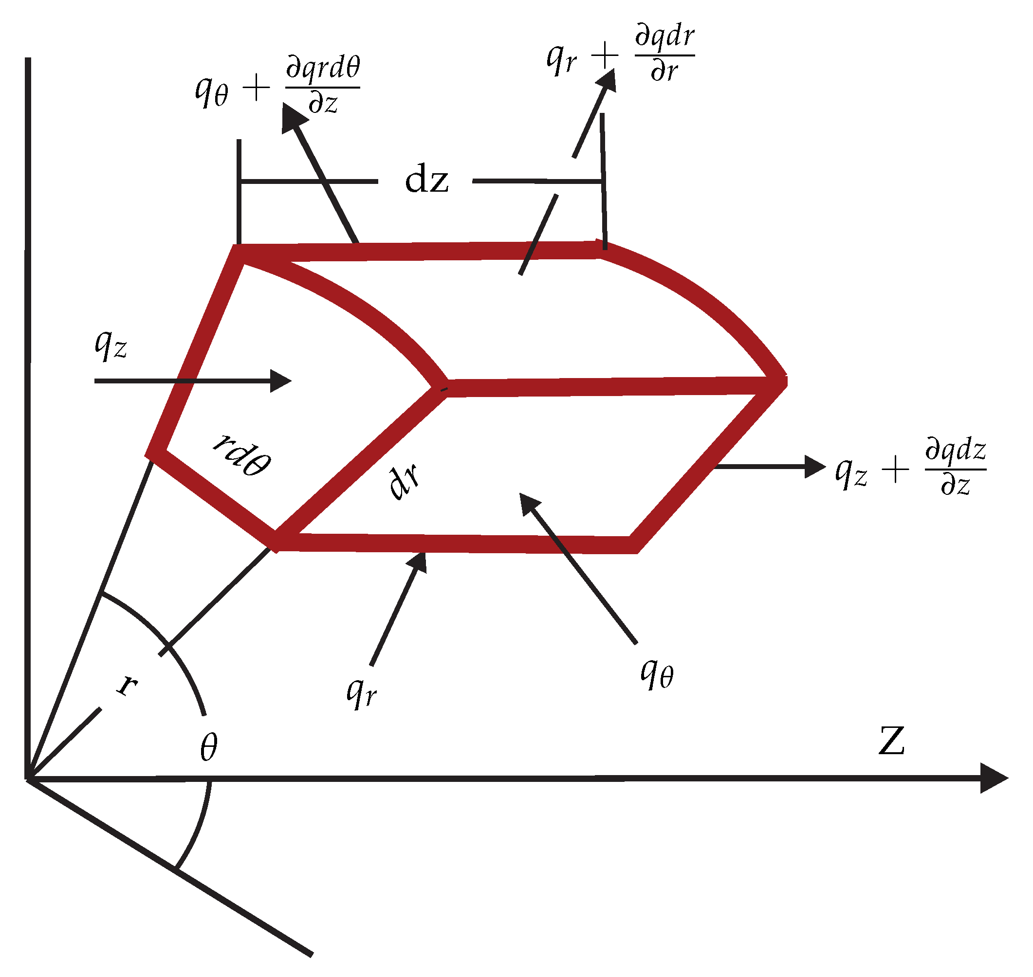
The temperature gradient is a function of time and can be solved by considering the energy balance as shown in Figure 2.
E n e r g y i n E n e r g y o u t + E n e r g y g e n e r a t i o n = E n e r g y s t o r e d
Accordingly, from Figure 2 and Equation (8), the general form of the heat generation equation is
1 r r K r T r + 1 r 2 K r T θ + z K r T z = ρ r c r T t + ρ r c r ω r T θ
Although an analysis of the 3-D problem is possible, this work is limited to a 2-D problem because 3-D problems exhibit complex situations to some existent. Ignoring the heat conduction along the rolling die axis, i.e., the z-direction, and considering a steady state condition, the thermal conduction at the top and bottom sides of the slab have been assumed identical, and then
1 r r T r + 1 r 2 T θ = ω κ r T θ
where ω is angular speed of the rolling die. Letting
T = ( r ) e i n θ
where ( r ) is a complex function, substituting Equation (11) into Equation (10), and simplifying the terms yields the differential equation which must be satisfied by
r 2 + r i n V r κ r r 2 + n 2 = 0
Following the procedure in Reference [16] with minor modifications on the last results and considering Drichlet’s conditions, the general equation of temperature distribution on the surface of a rolling die can be expressed by the following Fourier series
T ( r , θ ) = T a + A 0 + n = 1 { A n [ b e r n n P e r R c o s ( n θ ) b e i n n P e r R s i n ( n θ ) ] + B n [ b e r n n P e r R s i n ( n θ ) + b e i n n P e r R c o s ( n θ ) ] }
where b e r n and b e i n represent the Kelvin functions of order n and the Péclet number, P e = ω R 2 / κ
b e r n = 1 1 2 n 4 2 ! 2 + 1 2 n 8 4 ! 2 · · · = n = 0 ( 1 ) n 1 2 n 4 n [ 2 n ! ] 2
b e r i n = 1 2 n 2 + 1 2 n 6 3 ! 2 + 1 2 n 10 5 ! 2 · · · = n = 0 ( 1 ) n 1 2 n 4 n + 2 [ 2 n + 1 ! ] 2
Rather than a numeric calculation, one can find the Kelvin function values from mathematical handbooks such as in Reference [17]. Equation (13) is a general solution, while series coefficients A 0 , A n , and B n follow the specific thermal loading of boundary conditions. Thus, a full range Fourier series is considered from the physical meaning of the rolling die loads and are mathematically expressed as
A 0 = 1 π π π f ( θ ) d θ π 2
A n = 1 π π π f ( θ ) c o s ( n θ ) d θ 1 π n 2 1 n 1 , n = 1 , 2 , 3 ,
A n = 1 π π π f ( θ ) c o s ( n θ ) d θ 2 π 2 n + 1 2 , n = 0 , 1 , 2 ,
B n = 1 π π π f ( θ ) s i n ( n θ ) d θ ( 1 ) n + 1 n
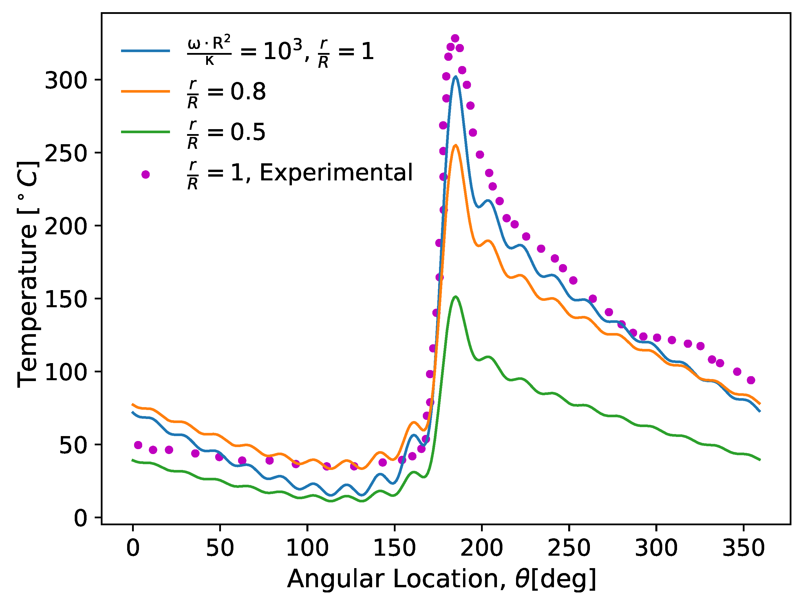
For this method, H13 tool steel is considered for rolling die with the following material properties: K r = 17.6 w/m· C, ρ r = 7.5 g/cc, c r = 0.460 J/g C, T s = 900 C, V r = 5 m/s and R = 100 mm. In the same way, A36 mild steel is considered for the slab where the thermal data are available in [6]. A computer program was written to compute the system of equations given in Equation (13) for various values of the input parameters and the output are compared with the experimental results as plotted in Figure 3. To validate the value of the proposed models, an experimental setup of the hot rolling was built. Since the rolling die with a diameter of 220 mm provides a better advantage, a scaled-down copy (1:5) of the industrial rolling die with a diameter of 1300 mm was used. The temperature measurements were obtained from the thermocouple sensors at depths of 0.2 mm from the surface. Throughout the rolling process, the thermocouple distribution and assembly in rolling die were made according to the procedure in Reference [18]. It is important to note that, in this experimental work, the maximum temperature on the rolling die surface reached about 370 C. Similar studies have shown that the die surface temperature in an industry rolling mill is around 550 C. The reproducibility of the experiments are tested by taking the measurements for the five cycles. Additional measurement procedures and data recording methods are available in References [19,20]. The plots in Figure 3 show the temperature distribution without specific information about the heat-transfer coefficient h w or the heat-input rate, q 0 . The best results were obtained whenever there were 30 terms ( n = 30 ) , but beyond this, the result deviated from the experimental validation because numerical problems were encountered in evaluating Kelvin functions whenever n was greater than 40. To tackle the problem, the optimization method was the best option as
T ˙ r θ = E 1 E 2 / ( E 3 + N ) , T ˙ r θ E 1 a s N
where E 1 , E 2 , and E 3 are constants and N is a natural number. The temperature distribution in the die is characterized by a thin layer at the surface of the die where thermal gradients are large. This layer, which is necessary to balance the heat transfer in the azimuthal direction (which is dominated by the die rotation) with the heat transfer in the direction (due to diffusion), does not contribute significantly to a thermal expansion of the die. The heat penetration depth can be obtained from
δ = r R = L c κ r V r
where L c is the length of the arc contact in a rolling gap.

3. Thermal Stresses in Hot Rolling Die

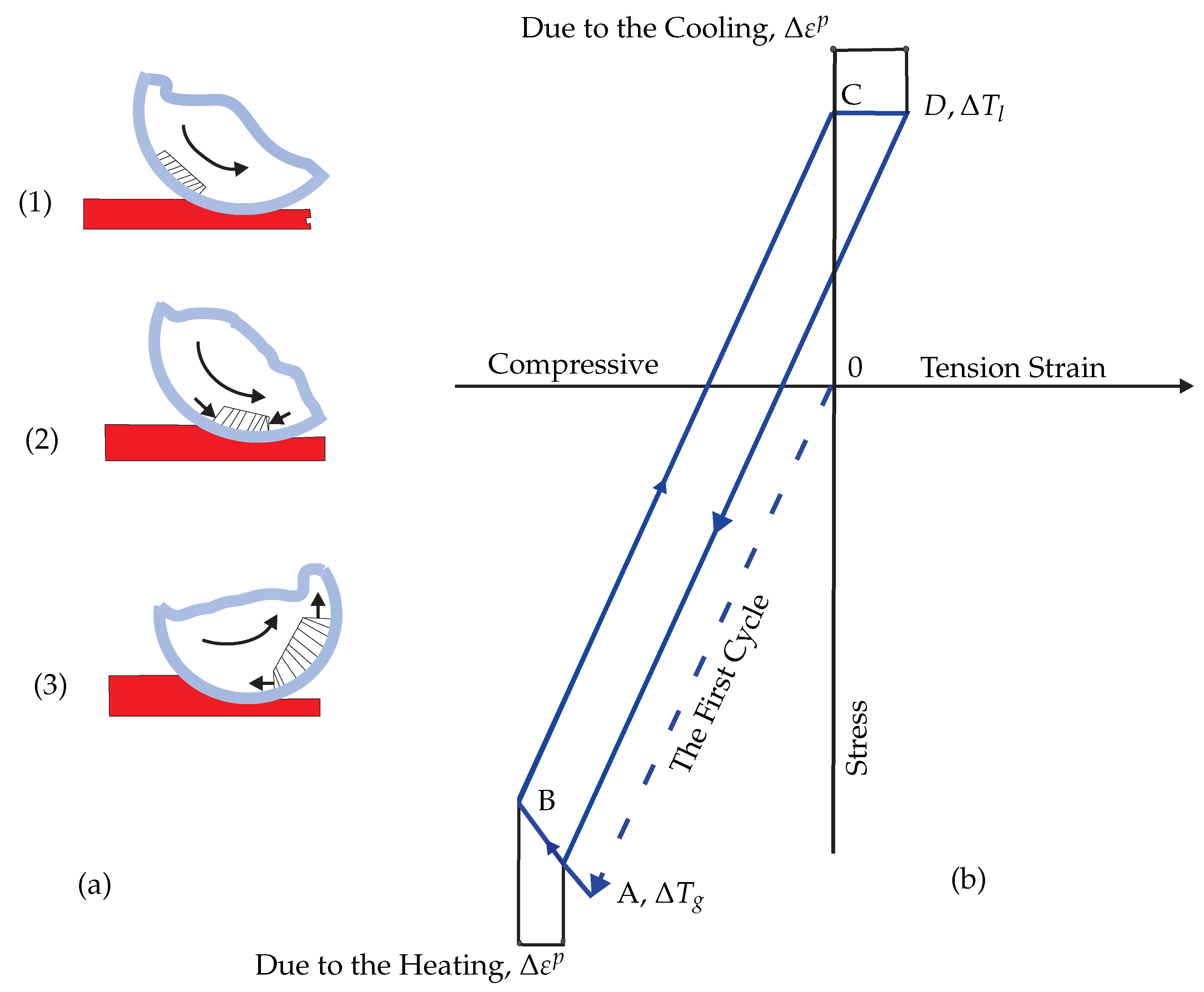
During hot rolling, heat energy is generated in the roll gap and a significant proportion is conducted through the die/slab contact to the die from which the heat should be removed by a cooling spray. Figure 4 shows the thermal and mechanical cyclic loads in the hot rolling process. Thermal actions develop over the entry of the die surface and are induced by conductive heating due to hot slab contact and forced convective cooling provided by water jets. A rolling die repeatedly rotates and then induces a cyclic sequence of cooling and heating phases on the surface of the rolling die, being responsible for the cyclic compressive and tensile stresses. A tangential expansion of the die surface, caused by the heating induced by hot slab contact, is constrained by the surrounding body materials, which remains at the lower temperature. Compressive stresses arise and may lead to local damage depending on the relative temperature difference between the rolling die surface and slab. In the same way, tensile stresses arise in the cooling area. Somehow, it seems that due to dual damage mechanisms, the temperature change in the cooling area may be converted to diametral expansion, and it can be given by
Δ d r = α r d r ( T g T w )
where d r and α r are the diameter and thermal expansion of a rolling die, respectively. A simplified method to estimate the elastoplastic cyclic behavior in hot work conditions for the die is developed as shown in Figure 4a,b. Assuming that compressive stresses in contact area due to heating (line OA) induce yielding stress at a temperature of certain value (point A), a further increase of the temperature may induce compressive plastic strains (line AB). The subsequent surface cooling produces tensile stress: first elastic stress (line BC) and then plastic stress (line CD). The loop closes in the subsequent heating. The approximate hysteresis loop (shown in Figure 4b) is constructed from the elastic, circumferential stress-strain loop with the following assumptions:
  • The circumferential stress is equal in magnitude to the yield stress during plastic deformation, and
  • The maximum circumferential strains are unaltered by the occurrence of the plastic deformation. The plastic strain amplitude of the hysteresis loop can be expressed by
Δ ε p = 1 E r τ θ m a x c + τ θ m a x t σ y c σ y t
where E r is Young modulus of the rolling die and τ θ m a x c and τ θ m a x t are the compressive stress at point A and the tensile stress at point C, respectively. For an ideal thermal cycle, all the thermal strains are converted into elastic and plastic strains. Thus,
Δ ε p = α r Δ T Δ σ E r
where σ y c and σ y t are the compressive yield strength and the tensile yield strength at the given temperature, respectively. The calculations for the displacements in a solid circular die body of outer radius R and length w z are given in which the temperature distribution is a function of the radial distance r or circumferential. For this case of plane strain, it is convenient to derive the basic equation of the problem. The formulation in terms of displacements in the die or cylindrical coordinates will be used for a general approach without considering body forces.
( λ + 2 G ) e r 2 G 1 r ω z θ ω θ z ( 3 λ + 2 G ) α r T r = 0
( λ + 2 G ) 1 r e r 2 G ω r z ω z r ( 3 λ + 2 G ) α r r T θ = 0
( λ + 2 G ) e r 2 G r ( r ω θ ) r ω r θ ( 3 λ + 2 G ) α r T z = 0
where λ and G are Lamé’s elastic constants which can be defined by
λ = ν E r ( 1 + ν ) ( 1 2 ν , μ = G = E r 2 ( 1 + ν )
where ν is Poisson’s ratio and e is the dilatation of the die defined by
e = 1 r ( r u ) r
where ω r , ω θ , and ω z are components of the rotation in the r, θ , and z directions, respectively, and the angular velocity of the die ( r a d / s ) . u, v, and w are components of the displacement vector in the r, θ , and z directions, respectively. Assuming w = v = 0 in equilibrium equations, omitting variations in the θ and z directions, and following the procedure given in Reference [21,22], the equilibrium equations reduce to
r 1 r ( r u ) r = α r 3 λ + 2 G λ + 2 G T r = α r 1 + ν 1 ν T r
u ( r ) = α r r 1 + ν 1 ν 0 R T r d r + C 1 r + C 2
Repeating this procedure for v ( θ ) and w ( z ) in the same way and specifying traction-free boundary conditions on the surface of a rolling die r = R , the constants C 1 and C 2 are obtained but first by determining the stress τ θ T h using the strain–displacement relations and Hooke’s law
τ θ T h = α r E r r 2 0 R T r d r + α r E r T + E r C 1 1 ν + E r C 2 ( 1 + ν ) r 2
Due to the radial symmetry and traction-free boundary conditions on the rolling die surface, σ r r = 0 at r = R . Thus, the constants C 1 and C 2 now can be determined. The final expression becomes
τ θ T h = α 1 E r R 2 f R 2 + S 1 + S 2 + α 1 E r r R 2 f r R 2 + S 3 + S 4 α E r T a + T s * A 0 + S 5 + S 6
where
T * = T s T a + ( β s 1 ) ( T r T a ) β s , β s = 1 + ( ρ c K ) r ( ρ c K ) s
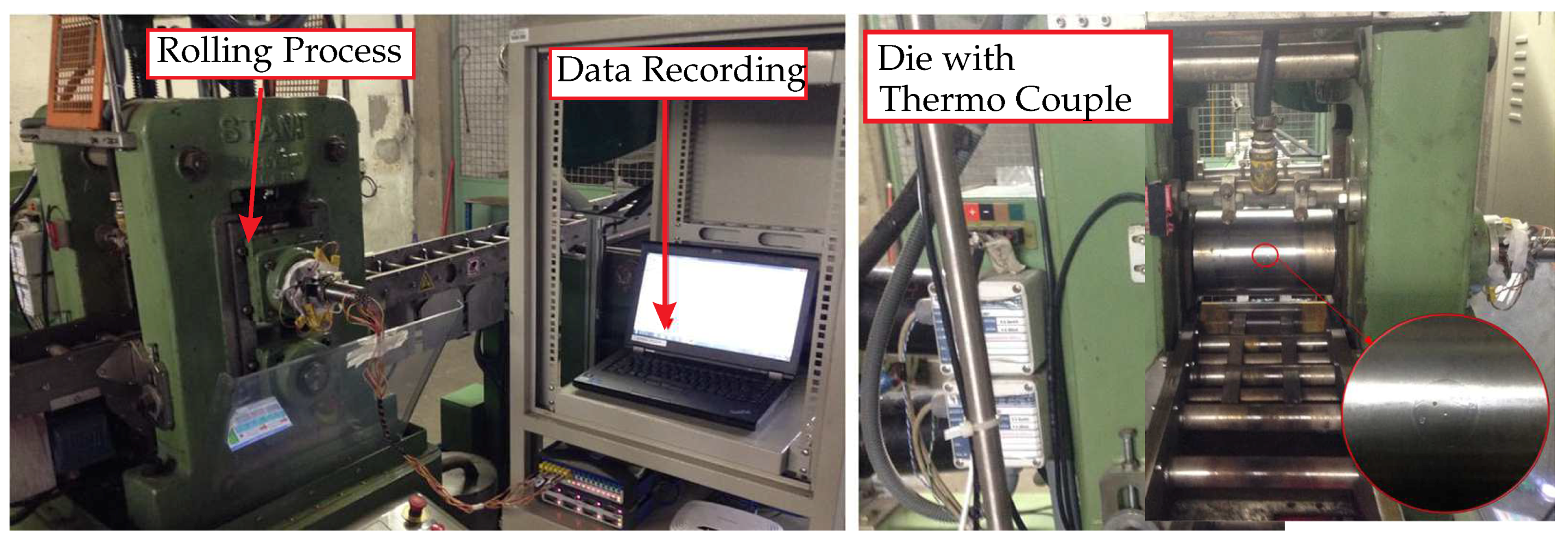
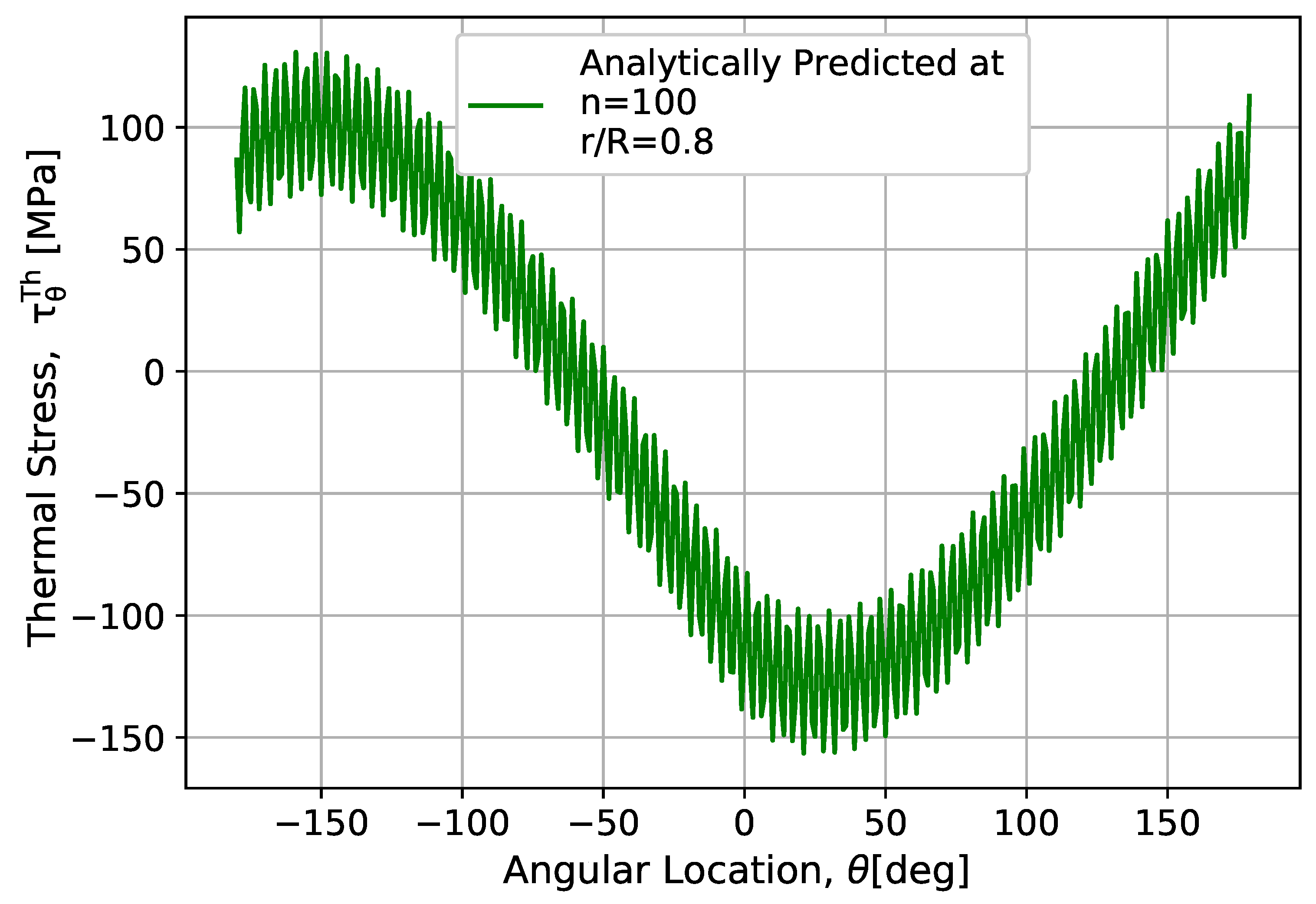
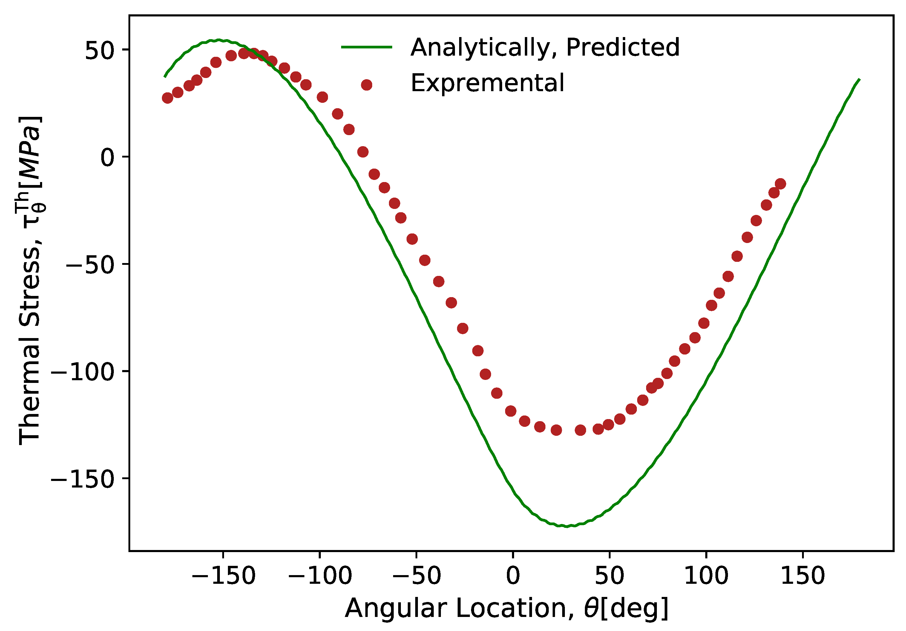
where T a is the ambient temperature and T r is the temperature on the surface of the rolling die before getting in contact with the slab. S 1 , S 2 , S 3 , S 4 , S 5 , S 6 , and f are given in Appendix A. To measure the thermal loads, thermocouple wires were used by implanting in the drilled holes of the rolling die body at the distance of 0.8 mm from the surface. The thermocouple measures the integrated temperature sensor at contact and at the cooling application. The thermal measurements give very detailed information about the temerature field. An inverse heat conduction mode has been developed to compute thermal stresses on the surface boundary condition from the measured temperatures. The Minitab® 17.1.0 software was used to analyze the experimental data. Figure 5 represents the setup of an apparatus for a thermal analysis under hot rolling. This rolling process represents complex equipment which corresponds to all the parameters of a hot rolling process incorporation in the technological process of industrial production. Regarding the factorial design and controlling, the mechanism detail information is found in Reference [23]. Considering the stress condition discussed in this section, the model is computed in the computational software (python), and the result is shown in Figure 6 and Figure 7. For this method, R = 100 mm, T s = 1000 C, and E r = 206.8 GPa were used. The result shows that circumferential stress can induce tensile and compressive stresses that can lead to thermal deformation under the plane-strain mode with the given thermal properties of the rolling die and rotational angles. As given in Figure 7, the results from the numerical analysis show an acceptable range of a good agreement with the experimental data.
In the same way, one can find the tangential strain using the following equations:
u ( r ) = α 1 r ( 1 + r ) 0 r T r d r + ( 1 ν ) r 2 b 2 0 b T r d r
Letting, w = u = 0, the angular displacement can be given as
d d θ 1 r d v d θ = α 1 1 + ν 1 ν d T d θ
The general solution of Equation (33) is
v ( θ ) = α 1 1 + ν 1 ν 0 θ t T r d θ + A r θ + B
where A and B are are constants. Once those displacements in Equations (32) and (33) are determined, we can compute ε θ θ :
ε θ θ = u r + 1 r v θ
Substituting Equations (32) and (33) into Equation (35), ε θ θ is given by
ε θ θ = α 1 ( 1 ν ) R 2 T a R + T s * A 0 b + D 1 + D 2 + α 1 ( 1 ν r / R T a r R + T s * A 0 + D 3 + D 4 α 1 ( 1 + ν ) r / R T a r + T s * A 0 r + D 5 + D 6
where D 1 , D 2 , D 3 , D 4 , D 5 , and D 6 are given in Appendix A. The correlation between fire cracking and the thermally induced stresses (thermal fatigue) in die surfaces has been discussed in Reference [24]. Assuming the die diameter to be infinite and the temperature in the die to be constant on planes parallel to the surface, the thermally induced strain ε T h at the surface can be predicted by
ε T h = α r T ˙ r θ 1 ν
where T ˙ r θ is obtained from Equation (13). If the plastic deformation on the die surface is small, the stress in the circumferential direction τ θ T h due to thermal effects and the rolling die pressure P can be derived from (considering the different experimental results that can be found in the literature)
τ θ T h = 1.43 α r T ˙ r θ E r + 0.39 P
The problem of Equation (38) is that it depends only on the temperature that is available on the surface of rolling die.

4. Mechanical Stresses and Constitutive Equation for Rolling Die

The problem of mechanical stresses of the rolling die is treated here by assuming that a solid cylinder is subjected to nonsymmetrical loads. The loading consists of the roll pressure and the interfacial shear stress, where the roll pressure is designated by P ( r ) and the interface shear stress is designated by τ r θ . These loads must be balanced by a statically equivalent force system, the location of which would depend on the type of mill considered. As the present analysis is concerned with a two-dimensional treatment of the rolling die of a two-high mill (usually used in continuous casting), die bending is neglected. The balancing loads are taken to be distributed over the dies with 2 ξ = π , where 2 ξ is the extent of the pressure distribution of the now imaginary backup roll instead of journal bearings. This condition ensures that the axis of the dies remains undeformed and stationary. The stress distribution in any problem of linear elasticity should satisfy the biharmonic equation, which in 2-D cylindrical coordinates is
r 2 + 1 r r + 1 r 2 2 θ 2 2 φ r 2 + 1 r φ r + 1 r 2 2 φ θ 2 = 0
where the coefficients of terms singular at the origin were taken to be equal to zero. The radial and shear stress terms are then obtained from the Airy stress function
σ r r = 1 r φ r + 1 r 2 2 φ θ 2
and
τ r θ = τ θ = r 1 r φ θ
The stress and strain distributions in the rolling die in a state of plane strain may be calculated from a stress function by using biharmonic functions
φ = c 0 r 2 + d 1 r 3 sin θ + d 2 r 3 cos θ + n = 2 a 1 n r n + b 1 n r n + 2 sin n θ + a 2 n r n + b 2 n r n + 2 cos n θ
where the constants a 1 n , a 2 n , b 1 n , b 2 n , c 0 , d 1 , and d 2 need to be determined such that the stress boundary conditions at r = R are satisfied. They are determined next by representing the normal and shear loading on the rolling die’s surface.
σ r r = P r and τ r θ = τ θ
where the normal and shear loading on the rolling die’s surface in terms of Fourier series is given as
P ( r ) = P a 0 + n = 1 P a n cos n θ + P b n sin n θ
and
τ ( θ ) = τ a 0 + n = 1 τ a n cos n θ + τ b n sin n θ
where the coefficients are obtained from the Euler formula. The normal pressure distribution is then expressed by
P a 0 = 1 2 π a 1 a 2 P θ d θ + π / 2 π / 2 R b θ d θ
P a n = 1 π a 1 a 2 P ( θ ) c o s ( n θ ) d θ + π / 2 π / 2 R b ( θ ) c o s ( n θ ) d θ
and
P b n = 1 π a 1 a 2 P ( θ ) s i n ( n θ ) d θ + π / 2 π / 2 R b ( θ ) s i n ( n θ ) d θ
Similarly, the shear stress distribution is given by
τ a o = 1 2 π a 1 a 2 τ ( θ ) d θ
τ a n = 1 2 π a 1 a 2 τ ( θ ) c o s ( n θ ) d θ
and
τ a n = 1 2 π a 1 a 2 τ θ sin n θ d θ
The function R b in Equations (46)–(48) represents the reactions required to keep the rolling die in equilibrium. This can be calculated by expressing the reactions using Fourier series.
R b ( θ ) = R 0 + n = 1 R a n cos ( n θ ) + R b n sin ( n θ )
and, again, where the coefficients are obtained by the Euler formula
R 0 = 1 π 2 R m ξ
R a n = 2 ξ R m c o s [ ( π + ψ + ξ ) n ] + c o s [ ( π + ψ ξ ) n ] π 2 4 ξ 2 n 2
R b n = 2 ξ R m s i n [ ( π + ψ + ξ ) n ] + s i n [ ( π + ψ ξ ) n ] π 2 4 ξ 2 n 2
In the above equations, ψ is the angle between the resultant reaction force and the vertical axis, R m is the amplitude of the reaction force, and ξ represents half of the angle over which reaction R b is distributed. It is noted that, for beyond two mills, the value of ξ may be determined from the Hertz contact stresses. However, as was mentioned above, for a two high mill, the reactions are represented by letting ξ = π / 2 , which, in fact, indicates the distribution of those forces across a diametral plane of the rolling die. Following the procedure given in Reference [25], the constants in Equation (42) are given as follows:
a 1 n = n P b n ( n 2 ) τ a n 2 n ( n 1 ) r b n 2 , a 2 n = n P a n ( n 2 ) τ b n 2 n ( n 1 ) r b n 2
b 1 n = P b n τ a n 2 n ( n 1 ) r b n 2 , b 2 n = P b n τ a n 2 n ( n 1 ) r b n
d 1 = P b 1 2 r b = τ a 1 2 r b , d 2 = P a 1 2 r b = τ b 1 2 r b
c 0 = P a 0 2
To determine the strain components, one can use the plane strain form of Hooke’s law:
ε r r = 1 + ν E r 1 ν σ r r ν τ θ , ε θ θ = 1 + ν E r ν σ r r + 1 ν τ θ
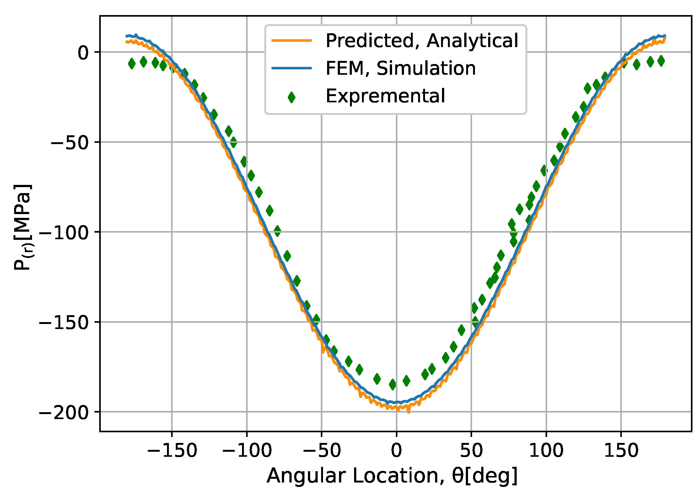
In this work, to evaluate the proposed models, an experimental setup was built. To get the experimental data, one set of optical fiber sensors is used under the rolling die surface (close to the surface). Sensors are glued into the blind bore beneath the surface, where a 50-mm cylindrical piece of metal is plugged. This plug is inserted into the rolling die, as shown in Figure 8, in order to measure the radial strain during the rolling process. The physical calibration system consists of all the apparatus coupled with mechanical components, electrical devices, and sensors during the data recording time. Strain gauge rosettes are integrated with the sensors to measure the strain at each point, where the stress can be calculated from strain values. Further details about this measurement procedure are also available in References [26,27]. The comparison between the analytic and finite element simulation results with experimental data is presented in Figure 9. Considering the initial load to be 90 MPa for both computational analyses, the result shows some variabilities, most likely due to the initial load over the whole cyclic contact during the experiment made.

5. Thermomechanical Stress

The model is proposed to determine the TM stresses in the rolling die during hot-slab rolling. TM coupling makes the analysis further difficult. Analytical approaches are impractical and sometimes inapplicable, while numerical approaches look very attractive [5]. Rolling die deformation is predicted in this section by employing the predicted temperature and thermal variations with imposing the mechanical boundary conditions in the deformation zone. In order to analyze the TM stresses, it has been assumed that strains in the axial direction may be ignored because the die length is very long compared to the depth of the surface layer where severe temperature variations take place. Thus, the die deformation may be considered as a two-dimensional TM problem. In the thermal effect, strains are produced by changes of temperature, ε i j T h . These strains have an inherent dilatational nature (thermal expansion or contraction). The total strains ε i j T M are obtained as a sum of the thermal strain and the mechanical strains ε i j M e
ε i j T M = ε i j M e + ε i j T h
σ i j = C i j k l ε i j M e = C i j k l ε i j ε i j T h
Note that the effect of body force, i.e., the mass effect of the rolling die has been ignored. Employing Hooke’s law constitutive equations, the stress and strain relationship equations are expressed as follows:
σ r r T M = ( 1 ν ) E r ( 1 2 ν ) ( 1 + ν ) ε r r M e + ν ( 1 ν ) ε θ θ M e 1 + ν 1 ν α r T ˙ r θ
τ θ T M = ( 1 ν ) E r ( 1 2 ν ) ( 1 + ν ) ε r r M e + ν ( 1 ν ) ε r r M e 1 + ν 1 ν α r T ˙ r θ
τ r θ m = G ε r θ M e
The stress–strain relation in three dimensions can also be formulated considering isotropic properties.
σ i j T M = λ t r ( ε ) I + 2 G ε i j E r α r Δ T I ( 1 2 ν )
Equation (66) is the generalized Hooke’s law that includes thermal effects, and its inverse relation is given by
ε i j T M = ν E r t r ( σ ) I + 1 + ν E r σ + α r Δ T I
where I is identity matrix. Furthermore, the strain and displacement relation can be given as
ε r r M e = u r r , ε θ θ M e = u r r + 1 r u θ θ , ε r θ M e = 1 2 1 r u r θ + u θ r u θ r
Also, the stress-displacement relations are
σ r r T M = ( 1 ν ) E r ( 1 2 ν ) ( 1 + ν ) [ u r + ν ( 1 ν ) u r + 1 v r θ 1 + ν 1 ν α r T ˙ r θ ]
τ θ T M = ( 1 ν ) E r ( 1 2 ν ) ( 1 + ν ) [ u r + 1 v r θ + v 1 v u r 1 + ν 1 ν α r T ˙ r θ ]
τ θ M e = G 1 r u θ + v r v r
In the thermal model, the temperature distribution within the die are calculated. At the same time, the results of the thermal model are implemented in the mechanical part to predict the TM stresses. Representative results of analytical computation shown in Figure 10 and Figure 11 are generated from the normal/radial stress and the shear stress components, respectively.
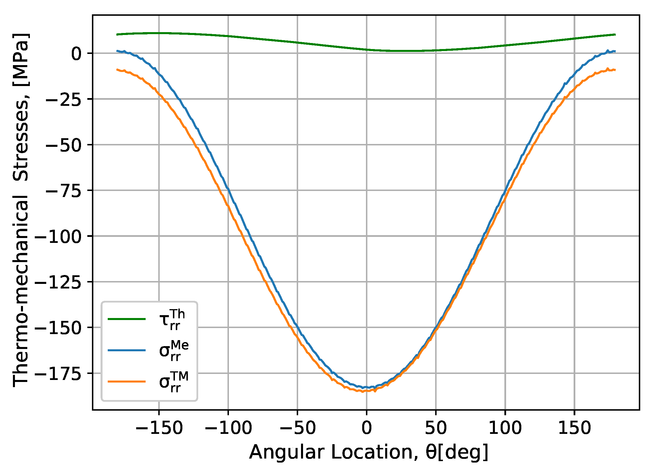
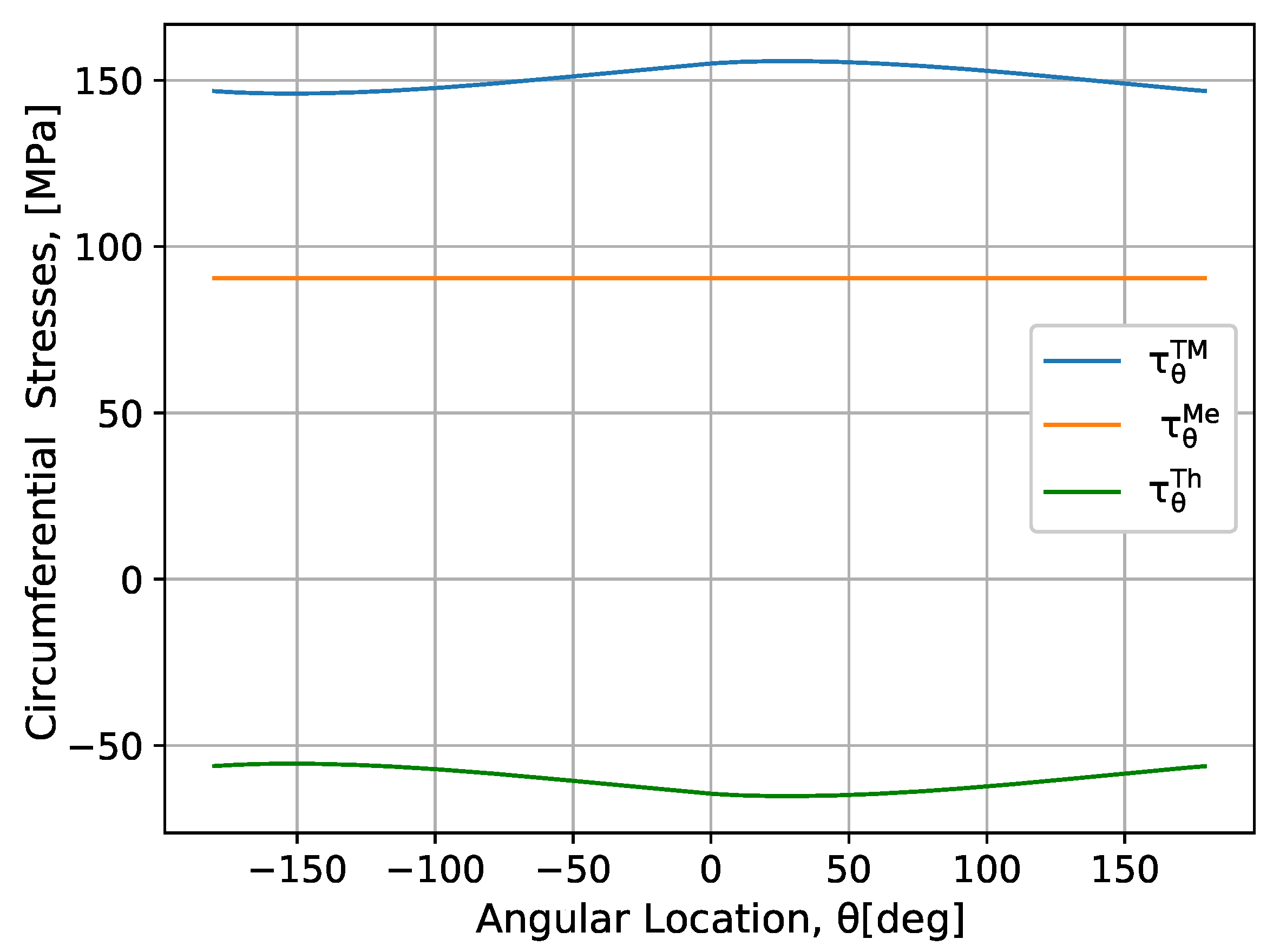
Figure 10 shows the comparison of the τ r r M e , τ r r T h , and τ r r T M stresses for a given number of cyclic loads and an initial contact load of 90 MPa. Upon comparison, a mechanical radial stress is greater than the thermal radial stress, where the coupled TM stress is more pronounced among the two stresses in the rolling gap. In the same way, a comparison is made for the τ θ M e , τ θ T h , and τ θ T M stresses that are shown in Figure 11, where the result show that the TM stress is the most damage contributor among the individual stresses. However, the direction of the τ θ M e and τ θ T h stresses are different in the rolling gap. At the end, the damage accumulation is obtained from the combination of the two stresses. In short, TM coupled stresses have a significant effect on a structure’s strength and stability of materials with all loading scenarios.

6. The Effect of Temperature on the H13 Tool Steel Material

It is known that engineering materials are selected for particular applications based on their mechanical and other relevant properties. An ideal material is expected to perform satisfactorily under severe loading and environmental conditions where the service loads and the environment change with respect to time. Materials used to perform at room temperature cannot be used at a high temperature because their mechanical properties degrade with the rise in temperature [28]. Fatigue may be one of the candidate failure mechanisms of components operating at room temperature; however, at a high temperature, in addition to thermomechanical fatigue (TMF), creep-fatigue interactions become important failure modes. Therefore, it is important to consider a candidate material that can sustain all loads. In hot and cold work tooling applications, H13 chromium hot-work steel is widely used [29]. This is because H13 has excellent combinations of high toughness and fatigue resistance much more than any other tool steel in hot-work applications. Further information about the H13 tool steel material is available in Reference [30].
Temperature affects the metal properties in numerous ways. A higher temperature can increase or decrease the properties of one metal. To provide an accurate representation of any physical system response, modeling must be considered in terms of a phenomenological representation of material properties like Young’s modulus E r , shear module G r , thermal conductivity K r , thermal expansion α r , density ρ r , etc.

6.1. Mechanical Properties of H13 Tool Steels

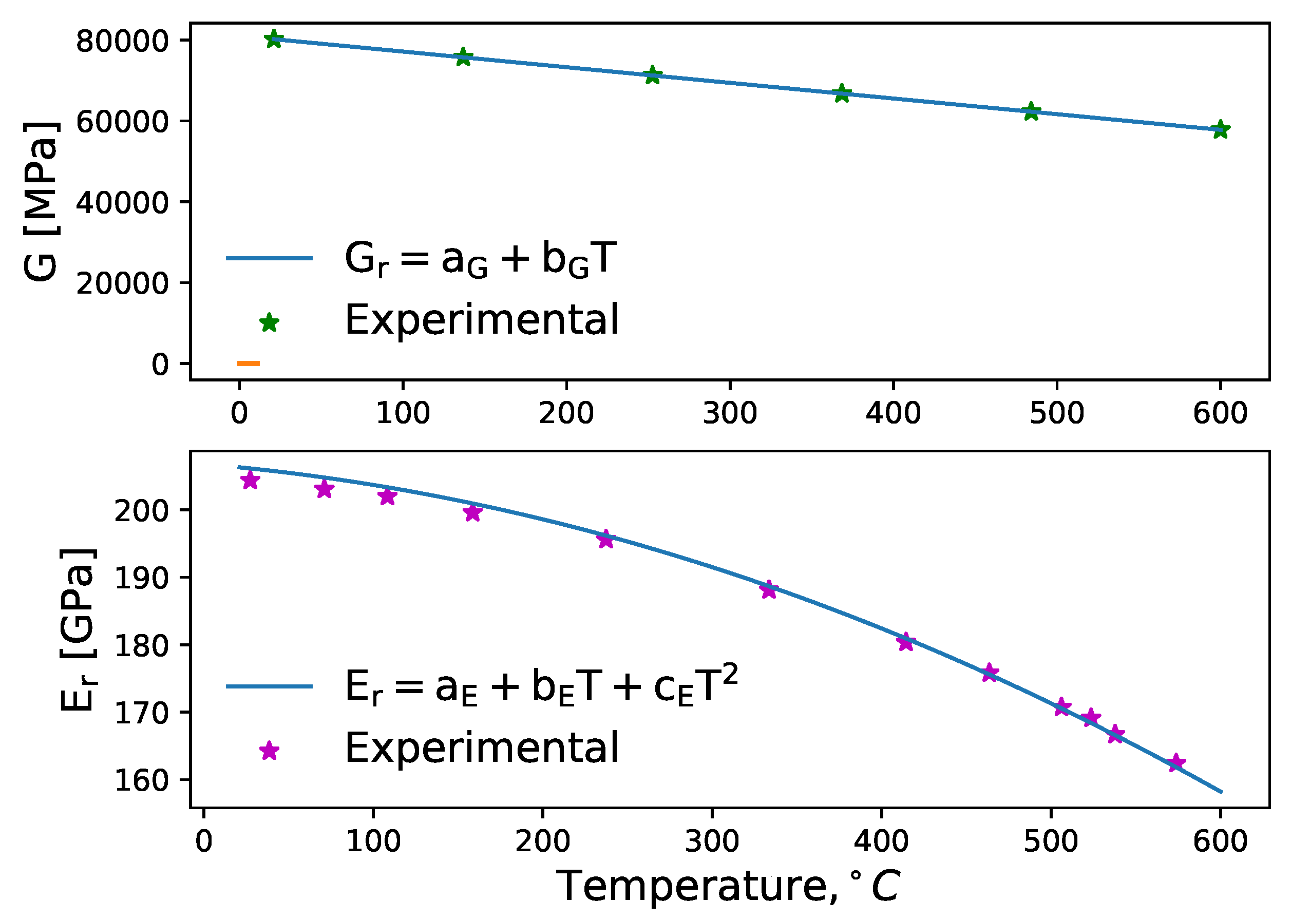
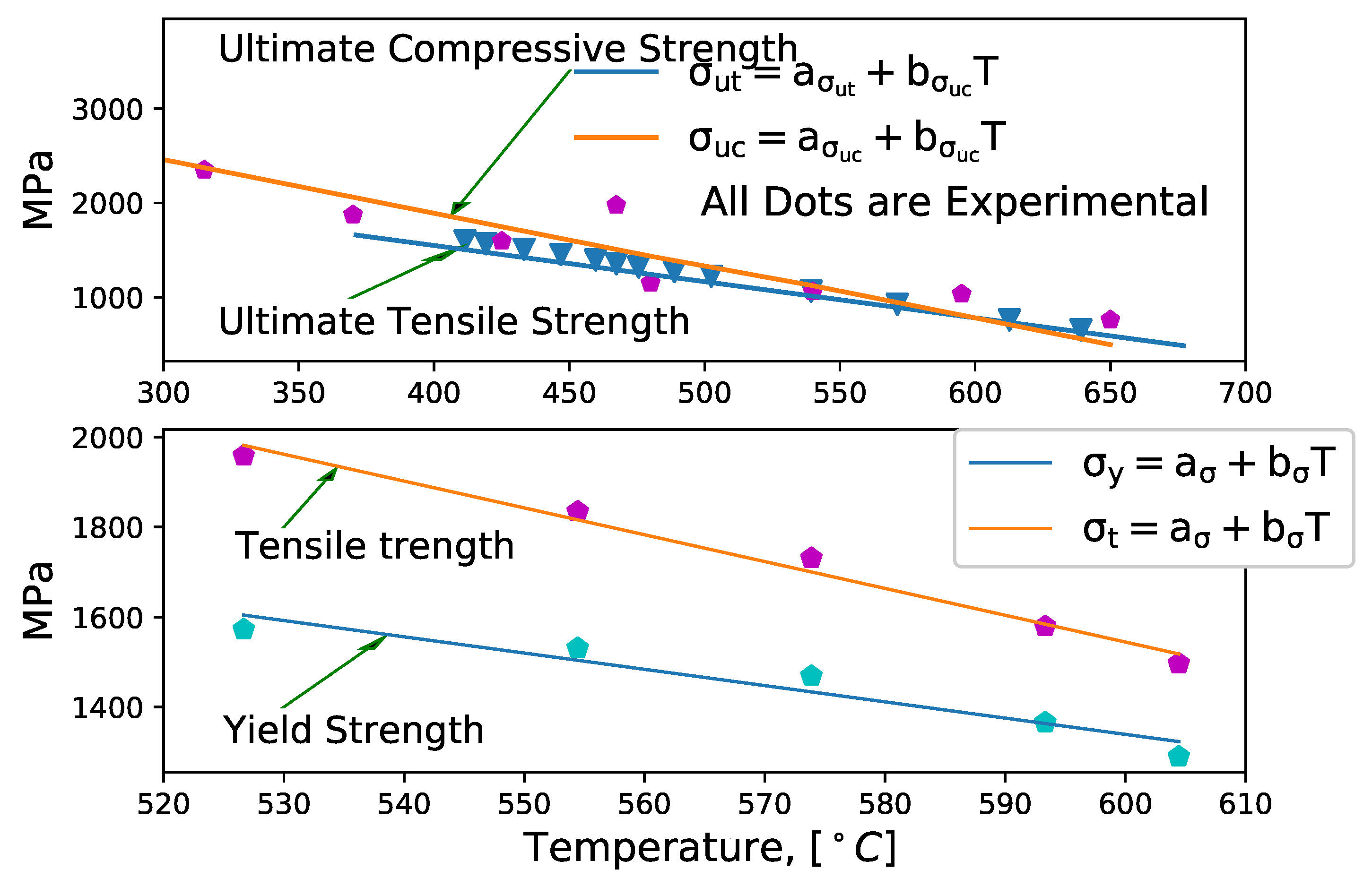
The mechanical properties of the H13 tool steel material model are proposed for various temperatures as given by Equations (72)–(74). Realistic results are depicted in Figure 12 and Figure 13 with the proposed constitutive equations and where the results show that mechanical properties of H13 tool steel material highly depend on the temperature variables. To obtain the values of assumed variables, optimization curve fitting is implemented corresponding to the experimental data, where values are given in Appendix B.
σ t = a σ t + b σ t T , σ y = a σ y + b σ y T
σ u t = a σ u t + b σ u t T , σ u c = a σ u c + b σ u c T
G r = a G + b G T , E r = a E + b E T + c E T 2
In Figure 13, it is observed that the proposed equations lead to an overestimation of the values in certain temperature ranges except Young’s modulus. This can have impacts on residual stresses, of which the conditions are mentioned in Appendix B.

6.2. Thermal Effect on H13 Tool Steel

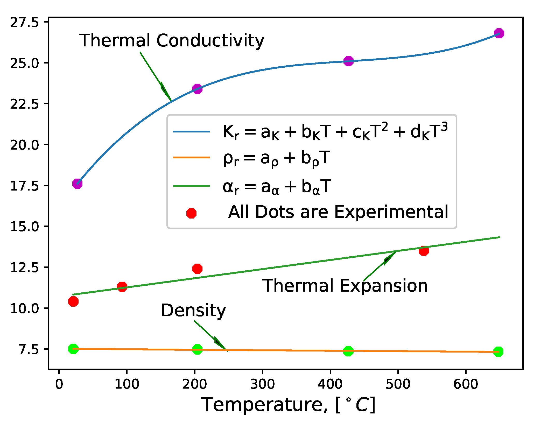
In the same way, the thermal properties of H13 material are extremely temperature-dependent (as depicted in Figure 14) except the density. Accounting for a wide range of temperatures, the H13 material response to thermal loads is modeled using a polynomial curve fitting method using the following relations
ρ r = a ρ + b ρ T
k r = a k + b k T + c k T 2 + d k T 3
α r = a α + b α T
where the values of the assumed variables are given in Appendix B.

7. Finite Element Simulation

Once the material properties are modeled, the next step is the finite element method (FEM) based modeling and performing the simulation. In this work, to perform a FEM simulation in the ABAQUS 6.14 software, the following steps are considered:
  • Material property specification
    (a)
    Specifying the known H13 tool steel material properties for the rolling die
    (b)
    Specifying A36 mild steel material properties (obtained from Reference [35] for the slab)
  • After the material properties are collected, the constitutive equations are implemented in ABAQUS via user-defined material model (UMAT) with the following steps:
    (a)
    A proper definition of the constitutive model,
    (b)
    A definition of the state variables,
    (c)
    Transforming the constitutive equation that perform the proper integration scheme,
    (d)
    A calculation of the Jacobian,
    (e)
    Code developing in the FORTRAN software,
    (f)
    Connecting the written code to the ABAQUS subroutine.
As can be observed from the steps listed above, conducting a FEM simulation in ABAQUS did not involve steps like geometry creation, mesh, etc., which are commonly practiced by many researchers in the area. In addition, the approach excludes the slab deformation result from the general solution by employing Bens.exe and Zedgrapp.dll, which are in-built functions in ABAQUS. More details of these steps along with illustrative examples can be found in Reference [36]. Moreover, ABAQUS offers many capabilities that enable the modeling of stresses. Especially, the Extended Finite Element Method (XFEM) and Dynamic Temperature Displacement Explicit are designed for continuous singularity and singularity-free problems. However, in ABAQUS/Explicit, the user-defined material models are implemented in user subroutine through vectorlized user-defined material model VUMAT, a procedure that is similar with UMAT. UMAT and VUMAT are used when none of the existing material models included in the ABAQUS material library accurately represent the behavior of the material to be modeled. Multiple user materials can be implemented in a single UMAT/VUMAT routine and can be used together. The target of the current study is to find suitable strategies to simplify the analysis and to allow a significant reduction of the computation time as well as to improve the accuracy of the modeling. This is motivated from the interest of finding alternative numerical approaches that can reduce the complexity of computations and equations.
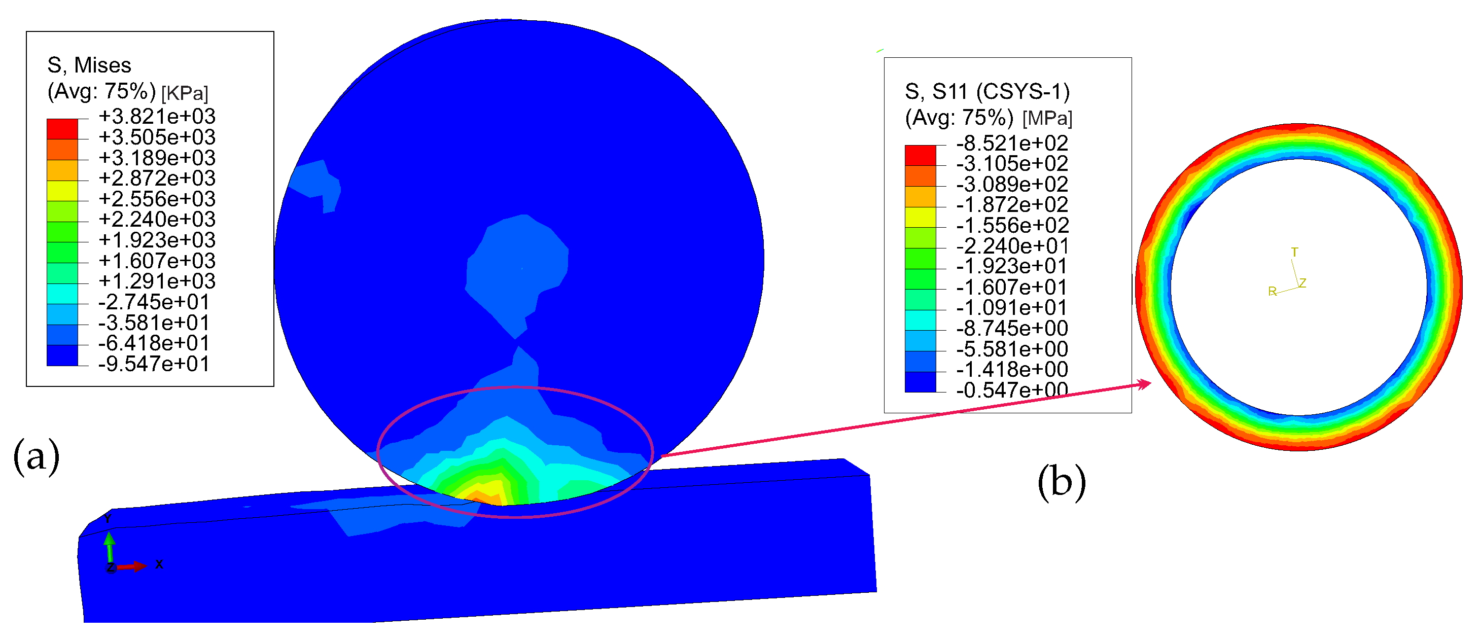
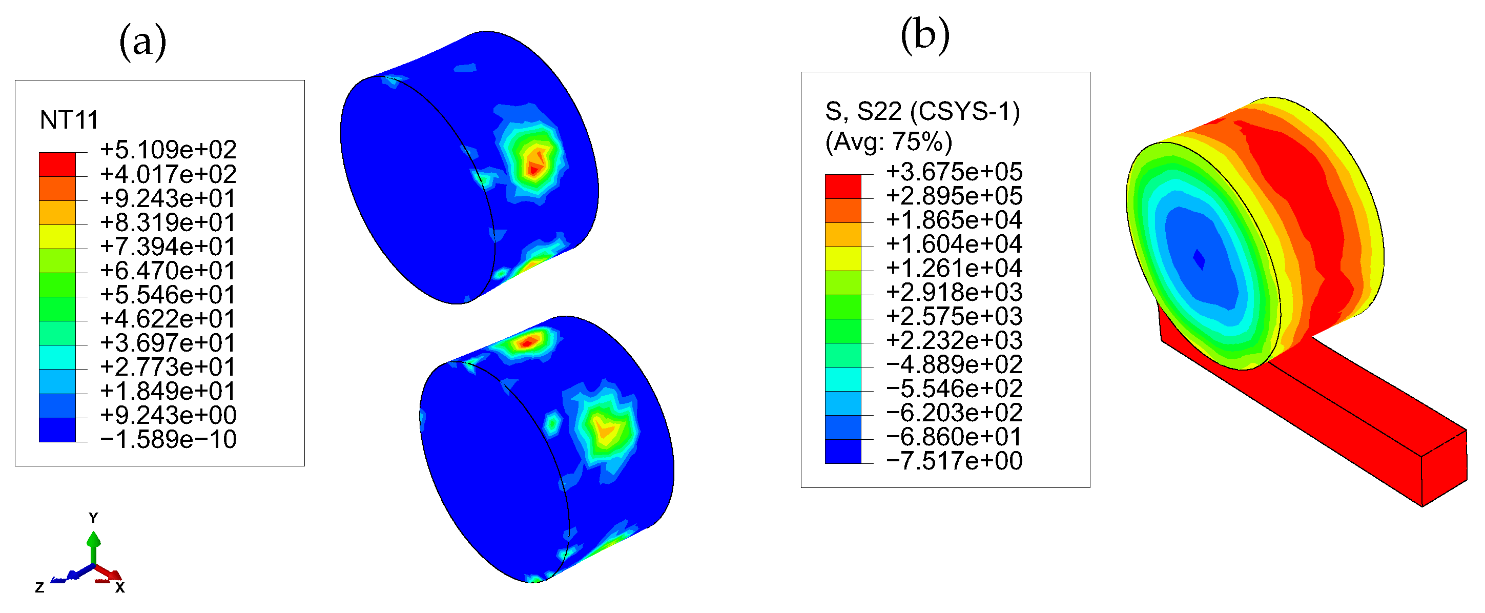
Representative results of the FEM analysis are shown in Figure 15 and Figure 16, in which cyclic contact damages are observed under the rolling gap and on the rolling die surface. This is an indication of surface failure in the material such as a pitting failure. The damage initiation and evolution of the observed cyclic contact damages can be characterized by the accumulated inelastic stress energy per stabilized cycle. In short, the results agree with the expectations and indicate a successful implementation of the constitutive model in ABAQUS.
The plastic damage occurring on rolling die surfaces has been characterized as a function of the temperature and loading history, as shown in Figure 16a. The thermomechanical stress distribution in the rolling gap is considered to describe the initial loads for the damage accumulation phenomena. However, a critical issue of this analysis consists of the accurate selection of all parameters as input for the numerical simulation, i.e., using a finite elements-based simulation, which is often difficult under this circumstance. This work has attempted to employ a simplified approach to compute TM in a rolling die of hot milling based on a damage evolution under the application of TM loads for a number of cyclic loads. The presented approach is obviously a preliminary investigation, in which the contribution is more methodological than quantitative. The model can be used as a tool in the most challenging aspect of hot rolling activities such as the identification of the elastic–plastic damage mechanisms in a rolling die. Actually, this approach looks quite promising, since it avoids analyzing the slab behavior in the rolling gap and enables the capture of relevant phenomena induced by rolling contact and identifies the damage evolution of the H13 tool steel behavior for the rolling die material.
The results from the numerical calculations are carried out based on the phenomenological application of hot milling under continuous casting applications for a number of cyclic loads. In short, the work reported in this paper demonstrates that the nature of a rolling die TM is damaged as a function of the stress distribution under the rolling gap. In addition, new models are proposed with the simplified versions for a hot rolling load condition where approximate values of loading phenomena are sufficiently predicted. Especially, H13 tool steel material properties in terms of mechanical and thermal properties are modeled for any temperature load, and it is observed that the values reasonably agreed with the experimental data. The TM model is extremely complex and important for engineering applications involving localized contacts, especially in the hot milling process. The repeated rolling die contact conditions cause permanent damage to the material due to the accumulation of deformation from the root cause of the thermal and mechanical loads separately or a combination of the main variables from both.

8. Conclusions and Outlook

This work proposes a simplified approach to compute the distribution of temperature, thermal stresses, mechanical stresses, and thermomechanical stresses for a rolling die under a continuous casting application. The models can be used as a tool in most aspects of hot rolling activities intended to identify the elastoplastic damage mechanism. The critical challenge of this work under this circumstance is a selection of parameters as input for the analytical analysis and finite simulation. Especially, to exclude the slab deformation result from the general solution, Bens.exe and Zedgrapp.dll should be executable with ABAQUS in addition to the UMAT/VUMAT implementation.
Stress distribution under the rolling gap in the radial direction computed by FEM simulations shows a good agreement with the results obtained by numeric solution as well as with experimental data. All models look promising, since the approach avoids the analysis of the slab in the general solution and is able to catch the relevant phenomena, which are induced by the heating and cooling application. The TM behavior is also identified with all possible load applications including a H13 tool material response at high temperature, which is poorly investigated in the literature. In fact, a deep experimental validation for the tangential coupled numeric model is strictly needed to allow a suitable model updating. The challenges are, however, the experimental setup is very complex, costly, and time demanding and it is difficult to complete existing hot milling processes that are used daily in manufacture processes. Moreover, the work focuses on the modeling of the hot milling damage evolution with full information from the beginning up to the date. Assuming all stresses can contribute to the damage evolution for a given number of cyclic loads. Further investigation, further investigation on crack growth on the surface of the rolling die, spalling information, and thermomechanical fatigue life prediction may be recommended as future works to take into account the results obtained in this study.

Author Contributions

M.A.T. did the former analysis and wrote the paper; H.G.L. was supervisor and critical review of the manuscript.

Funding

This research has no received any funding from external and internal institutes.

Conflicts of Interest

The authors declare no conflict of interest.

Appendix A.

  • The thermal stress part in the angular direction τ θ T h , where S 1 , S 2 , S 3 , S 4 , S 5 , and S 6 are given by
    S 1 = T s * n = 1 A n n [ e ( P e R n ) s i n ( P e R n n θ t ) 2 P e 2 + R c o s ( n θ t ) 2 P e n + ( R 2 P e n 1 2 P e 2 n ) s i n ( n θ t ) ]
    S 2 = T s * n = 1 B n n [ e ( P e R n ) c o s ( P e R n n θ t ) 2 P e 2 + ( 1 P e R n ) c o s ( n θ t ) 2 P e 2 n + R s i n ( n θ t ) 2 P e n ]
    S 3 = T s * n = 1 A n n [ e ( P e r n ) s i n ( P e r n n θ t ) 2 P e 2 + r c o s ( n θ t ) 2 P e n + ( r 2 P e n 1 2 P e 2 n ) s i n ( n θ t ) ]
    S 4 = T s * n = 1 B n n [ e ( P e r n ) c o s ( P e r n n θ t ) 2 P e 2 + ( 1 P e r n ) c o s ( n θ t ) 2 P e 2 n + r s i n ( n θ t ) 2 P e n ]
    S 5 = T s * n = 1 A n n e ( P e n ( R r ) ) c o s ( n θ t P e n ( R r ) )
    and
    f = 0 R ( T a r + T s * A 0 r ) d r
    where θ t = 2 π t t r , t is time or temporary coordinate ( s ) , and t r is the rotation period of a rolling die ( s )
  • The thermal strain parts in the θ direction ε θ θ , where D 1 , D 2 , D 3 , D 4 , D 5 , and D 6 are given
    D 1 = T s * n = 1 A n n [ e ( P e R n ) s i n ( P e R n n θ t ) 2 P e 2 + R c o s ( n θ t ) 2 P e n + ( R 2 P e n 1 2 P e 2 n ) s i n ( n θ t ) ]
    D 2 = T s * n = 1 B n n [ e ( P e R n ) c o s ( P e R n n θ t ) 2 P e 2 + ( 1 P e R n ) c o s ( n θ t ) 2 P e 2 n + R s i n ( n θ t ) 2 P e n ]
    D 3 = T s * n = 1 A n n [ e ( P e r n ) s i n ( P e r n n θ t ) 2 P e 2 + r c o s ( n θ t ) 2 P e n + ( r 2 P e n 1 2 P e 2 n ) s i n ( n θ t ) ]
    D 4 = T s * n = 1 B n n [ e ( P e r n ) c o s ( P e r n n θ t ) 2 P e 2 + ( 1 P e r n ) c o s ( n θ t ) 2 P e 2 n + r s i n ( n θ t ) 2 P e n ]
    D 5 = T s * n = 1 50 A n n e ( P e n ( R r ) ) c o s P e n r 1143 2500 + 50 π n T a 63
    D 6 = T s * n = 1 50 B n n e ( P e n ( R r ) ) c o s P e n r 1143 2500 + 50 π n T a 63

Appendix B. Parameters in the Curve-Fit of Material Properties Used in Simulation

  • The mechanical properties of the H13 tool steel from Figure 12 and Figure 13
    (a)
    Shear modulus, GPa
    A G r = 81 GPa, a G = 81 GPa, b G = 38.7 GPa
    (b)
    Young’s modulus, GPa
    A E r = 2.068 × 10 2 GPa, a E = 2.0681 × 10 2 GPa
    b E = 2.1 × 10 2 GPa, c E = 1.1 × 10 4 GPa
    (c)
    Yield strength MPa, valid only when T 526.66 C
    A σ y = 1380 MPa, a σ y = 3508.649 MPa
    b σ y = 3.616 MPa
    (d)
    Tensile strength MPa, valid only when T 526.66 C
    A σ u = 1650 MPa, a σ u = 5124.226 MPa
    b σ u = 5.9665 MPa
    (e)
    Ultimate tensile strength MPa, valid only when T 371.11 C
    A σ u t = 1990 MPa, a σ u t = 3083.84 MPa
    b σ u t = 3.836 MPa
    (f)
    Ultimate compressive strength MPa, valid only when T 150 C
    A σ u c = 3590 MPa, a σ u c = 4117.41 MPa,
    b σ u c = 5.6313 MPa
  • The thermal properties of H13 steel from Figure 14
    (a)
    Density, g/cc
    A ρ = 7.5 g/cc, a ρ = 7.5 g/cc,
    b ρ = 2.95 g/cc
    (b)
    Thermal conductivity, W/m · C
    A k = 17.6 W/m · C, a k = 16.13 W/m · C
    b k = 5.78 × 10 2 W/m · C
    c k = 1.29 × 10 4 W/m · C
    d k = 1.01 × 10 7 W/m · C
    (c)
    Thermal expansion coefficient, mm/mm C × 10 6
    A α = 10.4 mm/mm C × 10 6
    a α = 10.7 mm/mm C × 10 6
    b α = 5.57 × 10 3 mm/mm C × 10 6

References

  1. Shigeru, O.; Yosuke, N.; Thoshiyuki, S. Progress and Prospect of Rolling Technology; Nippon Steel Technical Report; UDC 621: Tokyo, Japan, 2012. [Google Scholar]
  2. Mercado-Solis, D.; Talamantes-Silva, J.; Hernandez-Rodriguez, A.; Beynon, H. Modelling surface thermal damage to hot mill rolls. Wear 2007, 263, 1560–1567. [Google Scholar] [CrossRef]
  3. Tseng, A.; Lin, H.; Gunderia, S.; Ni, S. Roll cooling and its relationship to roll life. Metall. Trans. A 1989, 20. [Google Scholar] [CrossRef]
  4. Sheikh, H. Thermal analysis of hot strip rolling using finite element and upper bound methods. Appl. Math. Modell. 2009, 33, 2187–2195. [Google Scholar] [CrossRef]
  5. Benasciutti, D.; Brusa, E.; Bazzaro, E. Finite elements prediction of thermal stresses in work roll of hot rolling mills. Procedia Eng. 2010, 2, 707–716. [Google Scholar] [CrossRef] [Green Version]
  6. Sonali, K. Effect of Temperature on Thermal and Mechanical Properties of High Strength Steel A325 and a490 Bolts. Master’s Thesis, Michigan State University, East Lansing, MI, USA, 22 April 2012. [Google Scholar]
  7. Der-Form, C. Thermal stresses in work rolls during the rolling of metal strip. J. Mate. Proc. Technol. 1999, 94, 45–51. [Google Scholar] [CrossRef]
  8. Galantucci, M.; Tricarico, L. Thermo-mechanical simulation of a rolling Process with an FEM approach. J. Mater. Process. Technol. 1999, 92–93, 494–501. [Google Scholar] [CrossRef]
  9. Dunckelmeyer, M.; Krempaszky, C.; Werner, E.; Hein, G.; Schorkhuber, K. Microstructure analysis of a banded work roll with comparison between damage appearance and thermo-mechanical considerations. In Proceedings of the International Doctoral Seminar, Bratislava, Slovakia, 16–19 May 2010. [Google Scholar]
  10. Sun, D.; Zhao, J.; Chen, L. Finite element analysis of temperature and crown of rolls in hot strip rolling. Appl. Mech. Mater. 2009, 16–19, 575–579. [Google Scholar] [CrossRef]
  11. Hongchun, L.; Jiang, Z.; Tieu, A.; Sun, W. Analysis of premature failure of work rolls in a cold strip plant. Wear 2007, 263, 1442–1446. [Google Scholar] [CrossRef]
  12. Sonboli, A.; Serajzadeh, S. Prediction of thermal stresses and temperature field in work rolls during hot strip rolling process. Mater. Sci. Technol. 2010, 26, 343–351. [Google Scholar] [CrossRef]
  13. Atack, A.; Robinson, S. An investigation into the control of thermal camber by spray cooling when hot rolling aluminum. J. Mate Proc. Technol. 1994, 45, 125–130. [Google Scholar] [CrossRef]
  14. Chen, W.; Samarasekera, V.; Kumar, A.; Hawbolt, B. Mathematical modeling of heat flow and deformation during rough rolling. Ironmaking Steelmaking 1993, 20, 113–125. [Google Scholar]
  15. Carslaw, H.; Jaeger, J. Conduction of Heat in Solids, 2nd ed.; Clarendon Press: Oxford, UK, 1959. [Google Scholar]
  16. Patula, E. Steady-state temperature distribution in a rotating roll subject to surface heat fluxes and conwective cooling. J. Heat Transfer 1981, 103, 36–41. [Google Scholar] [CrossRef]
  17. Abramowitz, M.; Stegun, I. Handbook of Mathematical Functions; McGraw-Hill: New York, NY, USA, 1970. [Google Scholar]
  18. Braga, A.; Lima, L.; GonÇalves, A.; Boccalini, M.; Souza, R. Coupled experimental-numerical analysis of Wear in hotrolling Mills. In Proceedings of the 10th International Tooling Conference, Bratislava, Slovakia, 4–7 October 2016. [Google Scholar]
  19. Raudensky, M.; Horsky, J.; Ondrouskova, J.; Vervaet, B. Measurement of thermal load on working rolls during Hot rolling. Steel Res. Int. 2013, 84, 269–275. [Google Scholar] [CrossRef]
  20. Zahradník, R.; Hrabovský. Study of the Work Roll Cooling in Hot Rolling Process with Regard on Service Life; Metallurgia Italiana. Available online: http://www.1391-Article%20Text-5287-1-10-20150225.pdf (accessed on 27 February 2019).
  21. Tseng, A.; Tong, V.; Raudensky, M.; Chen, C. Thermal Expansion and Crown Evaluations of Rolls in Rolling Processes. Steel Res. 1996, 67, 188–199. [Google Scholar] [CrossRef]
  22. Pérez, A.; Corral, L.; Fuentes, R.; Colás, R. Computer simulation of the thermal behaviour of a work roll during hot rolling of steel strip. J. Mater. Process. Technol. 2004, 153, 894–899. [Google Scholar] [CrossRef]
  23. Richman, M. Book Review: Juran’s Quality Handbook, 7th ed.; McGraw-Hill: New York, NY, USA, 2016; ISBN 9780070331761. [Google Scholar]
  24. Robert, W. Hot Rolling of Steel Manufacturing Engineering and Materials Processing; Marcel Dekker: New York, NY, USA, 1983. [Google Scholar]
  25. Mesay, A.; Altenbach, H. Numerical modeling rolling contact problem and elasticity deformation of rolling die under hot milling. Metals 2019, 9, 226. [Google Scholar] [CrossRef]
  26. Jeswiet, J.; Rice, W. The design of a sensor for measuring normal pressure and friction stress in the roll gap during cold rolling. In Proceedings of the 10th North American Manufacturing Research Conference Proceedings, Hamilton, ON, Canada, 24–25 May 1982; pp. 130–134. [Google Scholar]
  27. Weisz-Patrault, D.; Ehrlacher, A.; Legrand, N. A new sensor for the evaluation of contact stress by inverse analysis during steel strip rolling. J. Mater. Process. Technol. 2011, 211, 1500–1509. [Google Scholar] [CrossRef] [Green Version]
  28. Goswami, T. Creep-Fatigue Behaviour and Life Prediction. Ph.D. Thesis, University of Wollongong, Wollongong, Australia, 1998. Available online: https://ro.uow.edu.au/cgi/viewcontent.cgi? (accessed on 26 March 2019).
  29. Davis, J. Metal Handbook Desk Edition; ASM International: New York, NY, USA, 1998; pp. 265–289. [Google Scholar]
  30. AZoM. Tool Steels Molybdenum High-Speed Steels; AZO Materials: London, UK, 2016. [Google Scholar]
  31. Engerg, G.; Larsson, L. Elevated-Temperature Low Cycle and Thermomechanical Fatigue Properies of AISI H13 Hotwork Tool Steel; ASTM STP 942; ASTM International: West Conshohocken, PA, USA, 1988; pp. 565–577. [Google Scholar] [CrossRef]
  32. Steiner, R. ASM Handbook, Volume 1: Properties and Selection: Irons, Steels; ASM International: West Conshohocken, PA, USA, 1990; ISBN 978-0-87170-377-4. [Google Scholar]
  33. Harvey, D. Editor, Engineering Properties of Steels; American Society for Metals: Metals Park, OH, USA, 1982. [Google Scholar]
  34. Hudson. Tool Steel and High Speed Steel for Manufacturers; Tool Steel Corporation: London, UK; Available online: https://www.hudsontoolsteel.com/technical-data/steelH3 (accessed on 27 February 2019).
  35. Mesay, T. Modelling plastic deformation of A36 mild steel under extrusion process. Int. J. Eng. Res. 2014, 3, 1551–1555. [Google Scholar]
  36. Bower, A. EN234FEA. Computational Methods in Structural and Solid Mechanics; School of Engineering Brown University: Manchester, UK, 2012; Available online: http://www.brown.edu/Departments/Engineering/Courses/En2340 (accessed on 27 February 2019).
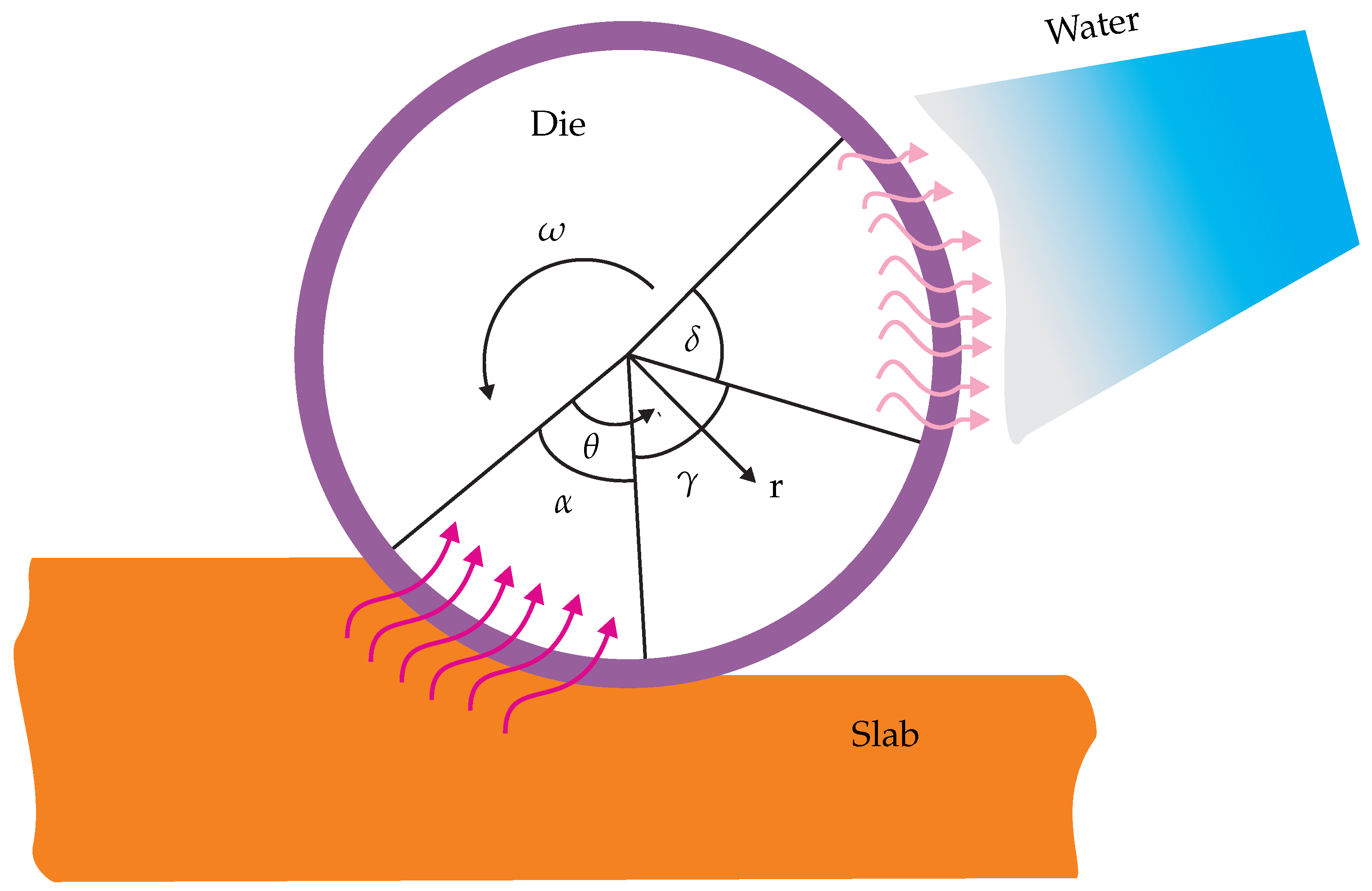
Figure 1. The heat gain and loss areas on the surface of a rolling die.
Metals 09 00495 g001
Figure 2. The differential controlled volume.
Metals 09 00495 g002
Figure 3. Plots of the temperature distribution in a rolling die at different depths.
Metals 09 00495 g003
Figure 4. A schematic diagram of the thermal cyclic load in hot working conditions: (a) The stress phenomena during heating and cooling and (b) the stress and strain closed loop for a point on the rolling die surface.
Metals 09 00495 g004
Figure 5. The experimental apparatus for thermal cycles.
Metals 09 00495 g005
Figure 6. An effective thermal stress distribution phenomena with given rotational angles and loads.
Metals 09 00495 g006
Figure 7. The circumferential thermal stress under full rotation where the number of cyclic loads is n = 1 × 10 2 for the numeric analysis.
Metals 09 00495 g007
Figure 8. The rolling die/annular for instrumentation: (a) An optic fiber sensor arrangement to plug into the drilled hole and (b) a typical optic fiber sensor position.
Metals 09 00495 g008
Figure 9. The radial stress distribution ( σ r r M e ) in rolling gap for a given number of cyclic loads.
Metals 09 00495 g009
Figure 10. Thermomechanical radial stresses: τ r r T h along the surface of the die and the σ r r M e and σ r r T M stresses under a roll gap which can produce the deformation stress on a rolling die depend on the number of cyclic contacts.
Metals 09 00495 g010
Figure 11. Thermomechanical tangential stresses: τ θ T h along the surface of the die and the τ θ M e and τ θ T M stresses under a roll gap which can produce the deformation stress on a rolling die depend on the number of cyclic contacts.
Metals 09 00495 g011
Figure 12. The normalized mechanical properties of H13 tool steel (experimental data source: [31,32]) and the parameters are given in Appendix B.
Metals 09 00495 g012
Figure 13. The normalized mechanical properties of H13 tool steel (experimental data source: [29,33]) and the parameters are given in Appendix B.
Metals 09 00495 g013
Figure 14. The normalized thermal properties of H13 tool steel (experimental data source: [32,34]) and the parameters are given in Appendix B.
Metals 09 00495 g014
Figure 15. The rolling contact stress field under a rolling gap: (a) the von Mises stress distribution under a rolling gap (Increment = 1 × 10) and (b) a sub-model of the radial stress distribution on the rolling die surface (Increment = 1 × 10 4 ).
Metals 09 00495 g015
Figure 16. The temperature and stress distribution on the rolling die surface where the slab temperature is T = 1000 C: (a) Heat generation and stress accumulation due to the contact under a rolling gap (Increment = 1 × 10 2 ) and (b) a tangential stress distribution (Increment = 1 × 10 5 ).
Metals 09 00495 g016