Article

An Investigation of the Adhesive Effect on the Flank Wear Properties of a WC/Co-based TiAlN-Coated Tool for Milling a Be/Cu Alloy

School of Machine Engineering and Automation, Fuzhou University, Fuzhou 350108, China
*
Author to whom correspondence should be addressed.
Metals 2019, 9(4), 444; https://doi.org/10.3390/met9040444
Submission received: 24 March 2019 / Revised: 12 April 2019 / Accepted: 12 April 2019 / Published: 15 April 2019

Abstract

:
In this paper, an experimental investigation, based on force special parameters, is adopted to analyze the relationship between the milling tool and adhesive phenomena in milling C17200. Generally speaking, the adhesive characteristics, force fluctuations, and tool failure are the main factors affecting the impact of the cutting process on tool wear patterns. However, difficult-to-cut materials, such as the beryllium–copper alloy C17200, require machining processes with tools with lives that are difficult to predict, due to their excellent mechanical properties. To analyze the tool failure process, a series of experiments based on cutting speed and tool geometry are presented in this paper to observe the adhesive effect on tool flank surfaces and force fluctuations. The results show that the variation of special force parameters in different directions reveals that the thermal–mechanical effect on sticking substances reached a possible peak value, with inflection points in different parameters at 200 m/min. The sticking substances and tool surfaces (observed by energy disperse spectroscopy and scanning electron microscope), wear capacity, and back-scattered electron imaging also confirmed that adhesion in the wear zone reached a peak value at 200 m/min in the cutting process, exacerbating the adhesive effect on tool failure.

1. Introduction

Non-ferrous metals have become significant industrial materials in aerospace, petroleum exploration, and other extreme working environments, due to their unique physical and mechanical properties [1]. It is well-known that industrial materials with excellent wear resistance are often used in critical components [2]. However, adhesive wear, based on the adhesion and self-lubrication of the materials, has become a significant influencing factor in non-ferrous metal processing in reducing the actual tool life [3].
Adhesion and self-lubrication are important machinability characteristics, which largely affect processing quality and tool wear mechanisms. A series of studies on non-ferrous metal machining has been carried out in detail by industry experts, which focused on the relationship between the grain structure and the processing technology. Liang and Liu [4] discussed the correlation between machined surfaces, tool wear, and crystal structure, and they pointed out that the effects of adhesion–abrasion are the main reason for the reduction in quality of the processed surface. Naskar and Chattopadhyay [5] investigated the flank wear mechanism on typical coated tools, and their results showed that plastic deformation, dissolution–diffusion, and abrasion were the crucial causes of tool failure. An investigation, based on tool wear rates and cutting parameters, was adopted by Sui and Feng [6] to analyze the influence of flank wear on the cutting force.
Many researchers have conducted a detailed analysis of elastoplastic deformation in the process, but machining damages, such as tool wear, fluctuation of the processed surface, and the unpredictability of machining, had not been explained [7,8,9]. So, a series of studies based on machining form and force modes were presented, to observe the relationships among dimensional accuracy, cutting parameters, cutting force, and machining processes. In the early 1990s, peripheral milling and force mode were discussed by Budak et al. [10,11,12], to understand the influencing factors of dimensional accuracy, and the results showed that the accuracy of the actual machining was greatly affected by the periodic variation of the milling. Mane et al. [13] discussed the influence of a spindle-bearing system on the chatter vibration in improving the quality of the processed surface.
Vettivel et al. [14] compared slice speed under different coatings to verify the effect of non-ferrous metal bonding on the coating. Pang et al. [15] presented a modified Oxley’s predictive theory to analyze the factors affecting the accuracy of theoretical models. A multi-objective optimization of a chip–tool interface was adopted by Mia et al. [16] to reduce tool wear and cutting forces, and the results indicated that the chip formation and friction parameters were greatly affected by the chip–tool interface situation. A novel mode of surface roughness variation, based on modal interaction, was presented by Seguy et al. [17], to observe the differences in processing systems.
Interestingly, many studies focused on the processing system itself, but rarely considered the combined effects of multiple factors. To analyze the machining environment effect on tool failure, the Fourier transformation was adopted by Wan et al. [18,19], to understand the accuracy of chatter stability with process force and energy balance principles. A novel theory of thermal–mechanical analysis, wear mechanisms, and cutting parameters was presented by Li et al. [20], to explain the main factors of tool failure in ultra-high-speed machining. Du et al. [21] put forward a new optimization approach for process parameters, to predict the possibility of surface integrity.
Zeng et al. [22] proposed a hypothesis of notch wear to verify wear processes, improve cutting efficiency, and reduce production costs in machining difficult-to-cut materials. Heigel et al. [23] attempted to measure the temperature at the tool–chip interface in cutting difficult-to-cut non-ferrous metals, to analyze the relationships between cutting temperature, cutting force, and the machining system. An improved temperature mode in the tool–chip contact region was adopted by Werschmoeller and Li [24] to describe the machining condition.
Additionally, An et al. [25] analyzed a Physical Vapor Deposition-AlTiN coated cemented carbide tool to satisfy the processing of high hardness materials. Martinho et al. [26] compared tool performance with the behavior of physical vapor deposition—and chemical vapor deposition—coated tools. Huang et al. [27] investigated the milling force by using signal analysis to identify cutting chatter, and the results suggested that the surface quality was positively correlated with the stability of the cutting process. A method of burr formation was indicated by Cheng et al. [28], to reduce and control top burr formation and improve the micro-milling surface quality. To further understand the milling process, Wang et al. [29] tried to explain the actual milling process by the equivalent cutting thickness method. However, due to the uncertainty of the adhesive process, the tool wear mechanism has rarely been analyzed by the correlations among sticking substances, tool coatings, and milling forces.
As described in [30], the actual force situation is largely affected by tool runout, cutting force expression, and the cutting system, and the complexity of different tool coatings makes the milling process diverse. To improve the force model, Altintas [30] proposed a modified model, based on the sustained average force and different feed rates, to calibrate six mechanical parameters to analyze the force on different cutting surfaces.
Some investigations indicated relationships among tool temperature, flank wear, tool material properties, and complex tool geometry, and the results showed that the temperature of the tool–chip interface is in negative correlation with the cutting speed [31]. The effect of the elastoplastic deformation of materials and the mechanical process of the cutter is rarely mentioned in the literature, which has become a real problem affecting the processing system. To understand the changes in machining, Wan et al. [32] proposed a blade force model, based on the separation process and elastic–plastic theory, to analyze the relationship between the plowing force and the dynamic cutting signal. However, the influence of the sticking process and wear mechanism on the machining system is still difficult to observe in traditional theory analysis, due to its randomness and unpredictability.
This work focuses on dynamic processes, the machining system, and cutting parameters to optimize machining quality which affects the processing costs. Few researchers have attended to observe the wear process and its mechanism, and the relationships among tool wear, work-piece characteristics, and force fluctuations are rarely understood. In this paper, an investigation based on an adhesion–abrasion wear model and adhesive effects is presented, to analyze the relationship between tool wear and force fluctuations.

2. Materials and Method

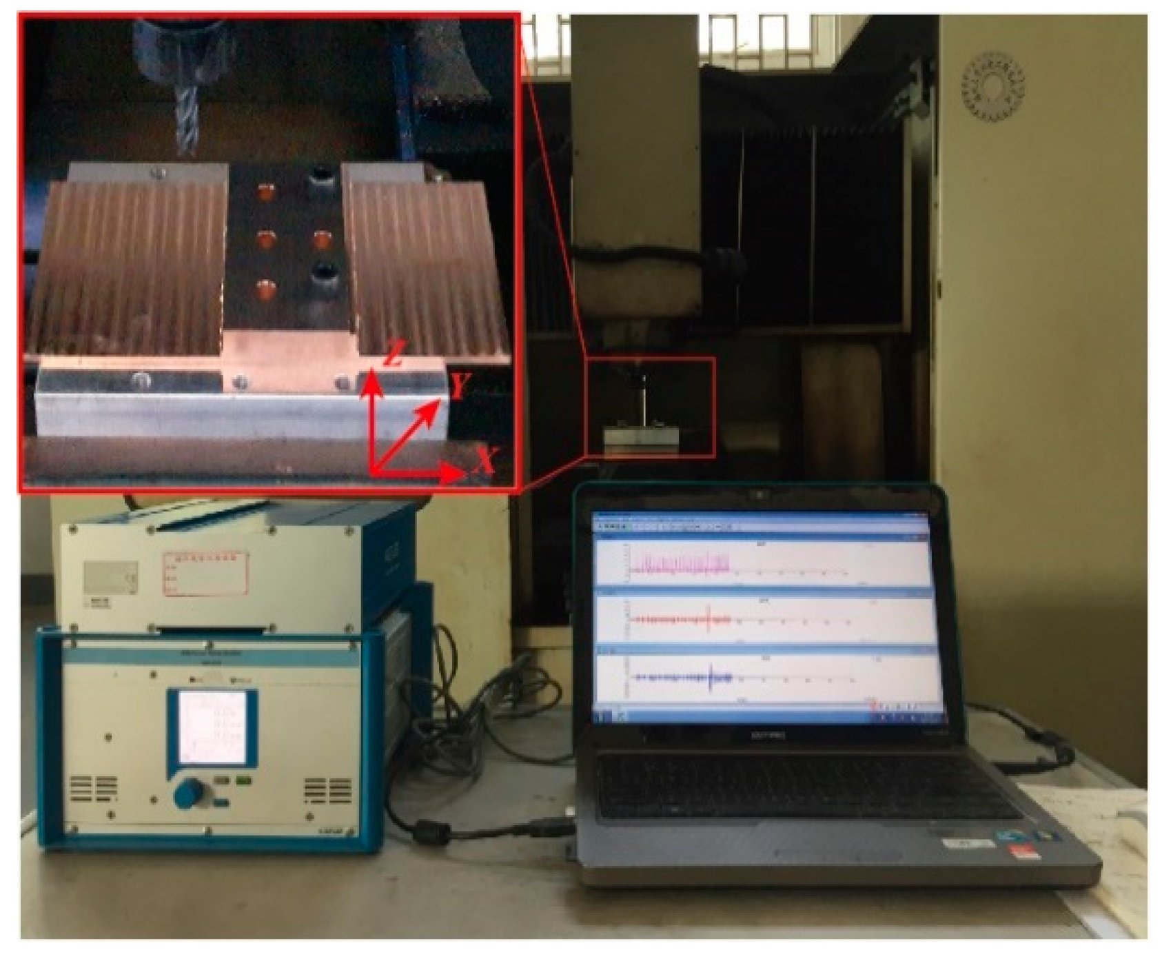
2.1. Materials And Experimental Setup

To verify the influence of the plow effect on tool wear, a series of experiments were adopted to analyze the relationship between the force parameters and the wear mechanism. The material, cut into dimensions of 200 × 100 × 10 mm3, used was a Beryllium–Copper alloy, C17200, whose chemical composition (as shown in Table 1) is Be 1.9%, Co 0.35%, Ni 0.20%, Si 0.15%, Fe 0.15%, Al 0.15%, and Cu to balance. The milling cutters (SH160-S4) were purchased from the Xiamen Golden egret special alloy Co. Ltd. (Xiamen, China), and the three-axis high-speed cutting machine (SXDK6050D, Ningbo jiangbei yongjin CNC machine tool Co. LTD, Ningbo, China) and test platform (9257B, Kistler, Bern, Switzerland) were adopted to monitor the actual change of cutting force, as shown in Figure 1.
Based on this situation, an orthogonal experiment, as listed in Table 2, was established, with varying cutting speeds (150–250 m/min), feed rates (0.05–0.15 mm/r), and depth of cut (0.5–1.5 mm), to obtain the wear pattern.
In addition, a single-factor experiment, based on cutting speed (150, 200, and 250 m/min) and feed rate (0.05, 0.1, and 0.15 mm), was set up to describe and calculate the situation of the cutting force, which largely indicated the dynamic process. Spectrum analysis was adopted to understand the composition of the wear process. Finally, tool wear was observed by a scanning electron microscope (TECNAI, G2 F20, FEI, Hillsboro, OR, USA) and the modified adhesion–abrasion wear model was used to explain the relationship between the milling process and tool wear.

2.2. Calculation of Cutting Force

In the proposed model, three independent forces, Fr, Ft, and Fa, as described by Altintas, were used as different discrete elemental elements to explain the three force components: radial, tangential, and axial, and their detailed expression given as
{ F t = K t c b h + K t e b F a = K a c b h + K a e b , F r = K r c b h + K r e b
where b is the chip width in the cutting element and h is the undeformed chip thickness.
{ F t c = b h [ τ s s i n n cos ( β n α n ) + t a n i t a n n s i n β n c o s 2 ( n + β n α n ) + t a n 2 n s i n 2 β n ] F a c = b h [ τ s s i n n c o s i sin ( β n α n ) c o s 2 ( n + β n α n ) + t a n 2 n s i n 2 β n ] F r c = b h [ τ s s i n n cos ( β n α n ) t a n i t a n n s i n β n c o s 2 ( n + β n α n ) + t a n 2 n s i n 2 β n ]
where b is the chip width in the cutting element, h is the undeformed chip thickness, the directions of shear velocity ( n ), chip flow (n), normal rake angle (αn), and average friction angle (βn), and the shear stress(τs).
The proposed model is based on continuous cutting conditions, as described by Altintas [30], which fully considers the influence of the cutter geometry on the unit cutter, and the oblique cutting force (again based on Altintas) could be obtained by
tan β = D φ 2 z   a n d   φ = 2 z tan β D ,
where the four unknown angles describe the oblique cutting; that is, the directions of shear velocity ( n ), chip flow (n), normal rake angle (αn), and average friction angle (βn).

2.3. Wear Process and Force Condition

It is well-known that copper elements have excellent adhesion, which causes an adhesive layer and built-up edges on the flank surface, but a cutting process with variable thickness often represents the instability of milling aggravating the tool wear process. Tool failure is affected by the fluctuation of machining and unpredictability of the sticking situation. The materials were divided into two parts to complete the material removal process and, so, the force could be broken down into three components (Ft, Fr, and Fa) to analyze the force process.
However, the sticking substances, adhesive layers, and built-up edges have become a significant factor which interferes with actual force process, largely causing changes in the mechanical components. Compared with the force situation and sticking processes, we can easily find that the effect of the sticking substance on the rake and flank surface is really different to just changing the force parameters, and the detailed force process could be obtained by
F 1 = T r a k e = F r t D = b h e [ τ s cos ( β a α r ) sin ( φ ) cos ( φ + β a α r ) ] D ,
F 2 = T f l a n k = F f t D = μ K s p V D ,
V = V s + V d ,
K q x = α q | F ¯ q x N a | ,
where D is the diameter of the milling cutter, he is the equivalent chip thickness, V is the mechanical volume, and αq is the coefficient variation parameter, which changes with the plow effect.

3. Results

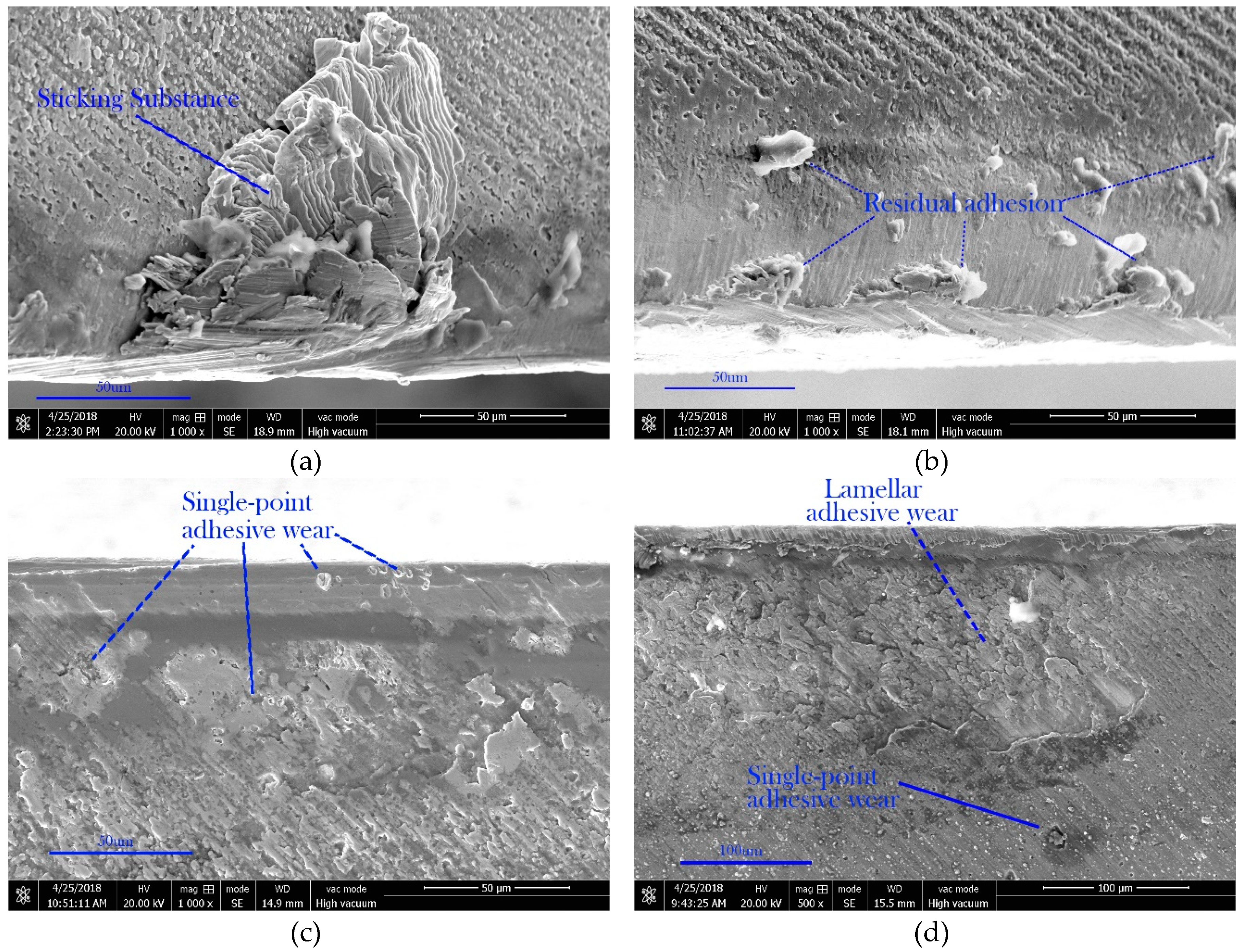
3.1. Spectrum Analysis and Sticking Substance

Sticking substances have become important influencing factors with the continuous improvement of machining accuracy. As Figure 2 describes, their adhesion and forms are various, due to the instability of the milling process and material characteristics. Generally speaking, tool surfaces can be categorized into the following four types: (a) sticking substances on the tool surface; (b) residual adhesion; (c) single-point wear; and (d) lamellar wear.
Compared with traditional metals, the tool wear in non-ferrous metal machining is largely affected by the change of the sticking process. When the milling process begins, the work-piece materials begin to adhere to the tool surface continuously, due to the thermal softening effect and the complicated contact form between the work-piece and tool surface has become a significant factor in reducing actual tool life.
As Figure 2 shows, sticking substances on the tool surface have become important products which affect the machining process. The tool life is reduced by the adhesive process caused by the material characteristics. To observe the influence of sticking substances on the cutting process and tool-failure mechanisms, a spectrum analysis based on the region of adhesion–abrasion wear is presented, and the results show that a large amount of the work-piece material severely remains in the worn area of the cutter. The morphology of the wear region indicates that the process of adhesion–abrasion and tool wear is inter-dependently dynamic.
Figure 3 shows the tool wear pattern versus sliding time under the same feed rate, from 150 m/min to 250 m/min. The running-in friction stage can be obviously noticed from the adherent phenomenon. The greater the cutting speed, the closer the contact of accumulation on adhesion, which meant that the work-piece materials will have adhered to the tool surface, causing more sticking substances to influence the wear process.
Figure 4 illustrates the components of the tool surface at feed rates of 150 m/min, 200 m/min, and 250 m/min. In the sliding friction process, the work-piece materials were adhesive at the tool surface, due to the action of self-lubricity. It is evident that the tool surface was also covered with an adhesive layer at all cutting speeds. On the one hand, the reduction of Cu elements on the tool surface with an increase of cutting speed does not mean the decrease of sticking substances; it just means that the bonded materials fell off easier, which exacerbated the tool wear process easier. On the other hand, the variation of Ti elements could be an important index to indicate that the speed of 200 m/min had the minimum wear value.

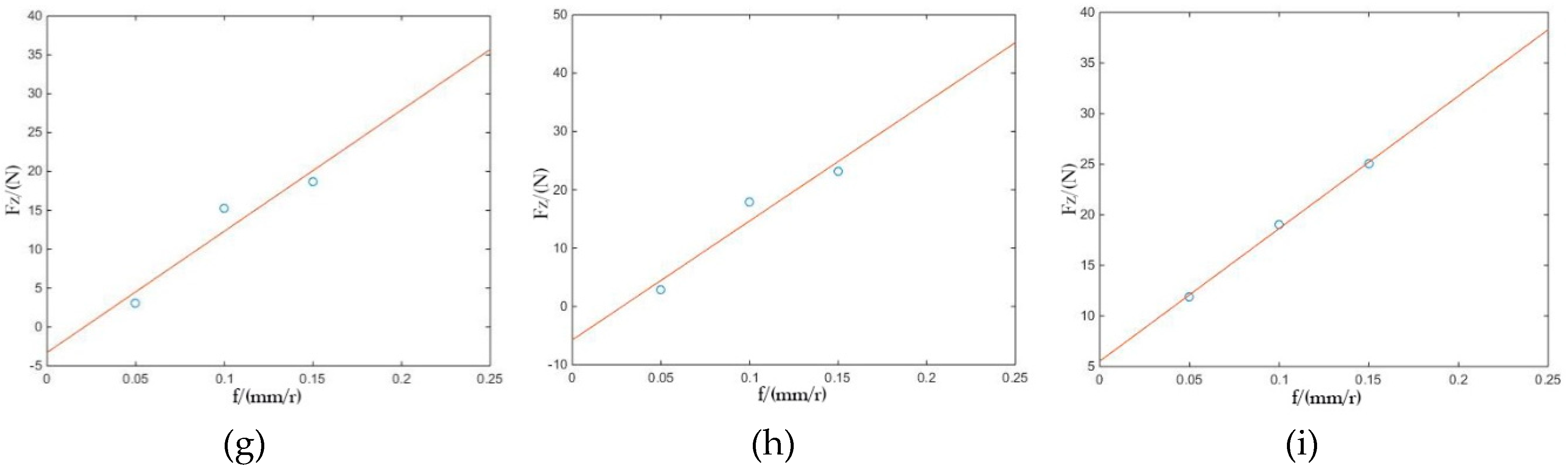
3.2. Cutting Force and its Parameters

Due to the adhesive characteristics of the milling process, variation on tool surface, as in Figure 4, will sustain the constantly-changing tool surface condition. Compared with the theoretical force, because of its adhesive effect, the actual force based on adhesive wear has become a significant reason in the reduction of tool life, which will lead to more instability.
To observe the relationship between the adhesive effect and force, the calibration of cutting force, based on cutting speeds at 150 to 250 m/min was adopted to identify the fluctuation of force parameters which can represent the force trend of the cutters. The specific force coefficients ( F ¯ q c   and   F ¯ q e ) can be obtained by a linear regression of the data using different milling processes.
Figure 5 shows force fitting in three directions under different cutting speeds, using the same type of milling cutters to simulate similar milling process. The force parameters are calibrated as the cutting speed increases, and the results show that a cutting speed of about 200 m/min is the inflection point of the parameter; which means a change in cutting force and its direction, caused by the cutting speed. Additionally, it shows that the force direction is not as stable as expected to explain the tool wear mechanism and the actual force values in the linear calibration.
To verify the difference, Figure 6 illustrates a two-dimensional parameter variation of the single-factor experiment, using TiAlN coated tools. The results showed that the force parameters of TiAlN coated tools, under different cutting speed, have a turning point, which indicates that the force on the cutting edges gradually changes as the cutting speed increases. It can be noted that the cutting speed at 200 m/min could be an important factor in implying a variation of the milling process.

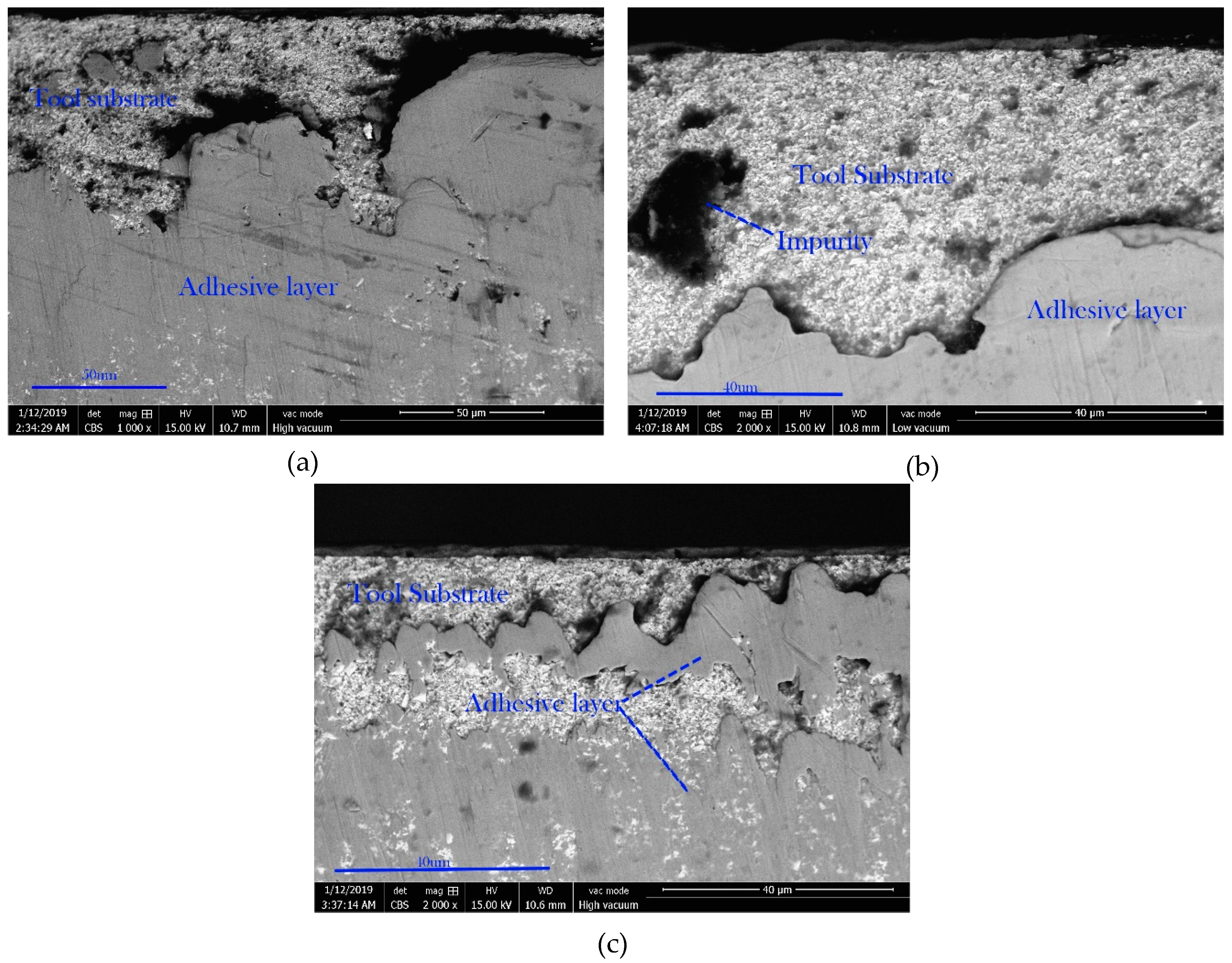
3.3. Wearing Capacity and Back-Scattered Electron Imaging

The coating condition of the tool surface at three different speeds is detailed in Figure 7. Smaller adhesive layers of work-piece materials after 20 m of processing distance could be obtained by tools with a higher cutting speed. In particular, the sticking substances had a significant factor of influence in the wear process. After a milling distance of about 20 m, it could be seen that the worn areas in the back-scattered electron imaging appeared to be brighter as the cutting speed increased, which means that more tool materials were observed in the wear zone. This may be due to serious flank wear occurring on TiAlN coated tools, which contributed to the adhesive layers.
To verify the influence of sticking substances on flank wear, the wear capacity after 20 m of processing distance, material adherent rate, and material removal rate are listed in Figure 8. Tool wear on the flank surface can be clearly seen in Figure 8, and it is noted that the tool wear is obviously positively correlated with cutting speeds with different slops. Nevertheless, the adhesive rate of the tool flank wear in the wear zone decreased obviously, compared with that in the non-wear zone.

4. Discussion

In this paper, the wear process was, respectively, analyzed by experiments with three kinds of cutting speeds and feed rates, and a single-factor experiment adopted to understand the force rule with the cutting speed. The results exhibited that the adhesive layer on the tool surface significantly affected the wear process of C-W/Co tools with a TiAlN coated flank face used for the dry-milling of the Beryllium-Copper alloy C17200. The relevant mechanisms are discussed below.
The basic morphology of the wear areas and their principal component analysis are exhibited in Figure 2 and Figure 3. It was shown that the more serious flank wear in dry-milling C17200 was affected by a thermal–mechanical effect caused by adhesion behavior. In the sliding friction process, the sticking substances, adhesive layers, and their composition are as listed in Figure 4. It is worth noting that the cutting force parameters can be used in illustrating the effects of a built-up edge on the flank surface, which is difficult to characterize due to the complexity of typical milling cutter geometry. Figure 5 shows the floatation values of cutting parameters to identify variation trends of the local forces, and the results showed that a downward trend was presented in the shearing action (Kac) and that a turning point at 200 m/min was indicated in the shearing action (Krc and Ktc) and edge action (Kae and Kre). Additionally, there was a continuous upward trend in edge action (Kte), which indicates that the cutter bears more severe lateral force in the milling process.
At this point, it is possible to investigate the condition of the tool surface under different cutting parameters. Fillot et al. [33] reported the relationship between adhesion particles and the wear process and pointed out that the physicochemical parameter plays an antagonistic role on the wear process. As in Figure 2 and Figure 6, sticking substances and adhesive effects have become the most important factors which affect tool life. Figure 2 shows several common forms of flank wear, and the exfoliation of a sheet or mass is a common form of tool wear. As the actual milling starts, a thermal–mechanical effect will be generated by the plastic deformation in the first deformation zone, which causes the sticking of substances and built-up edges. The tool geometry changes dynamically in the milling process, due to repeated adhesion shedding. Therefore, a bigger milling force is required to deal with the increased front angle of the cutter generated by the built-up edges. Considering the trend of the decomposed force and the stressed state of the crystal, four kinds of tool surface morphology clearly reflected the effect of adhesive behavior on tool wear.
Furthermore, the results of force analysis showed that tools bear a greater force fluctuation at the cutting speed at 200 m/min. Based on the results given in Figure 5 and Figure 6, the adhesive layer may greatly affect the tool geometry within the cutting speed range, which causes the variation of force parameters [34]. The fluctuation of the special force parameters with different milling speeds was calculated in this paper to verify the possibility of being caused by an adhesive layer, and the results showed that the cutting force parameter (K) produced a relatively obvious turning shape at 200 m/min. Compared with traditional wear processes, there is a different tendency between cutting speed and tool wear. In the traditional force situation, the force F has bigger effect with an increase in cutting speed. As illuminated by Figure 6, it can be deduced that the cutting force and its direction subversively change as the cutting speed increases. At the same time, tool wear with variable force changes dramatically, which has a great effect on work-piece precision. Meanwhile, the thermal-softening effect begins to take place, and the built-up edges become larger when the cutting speed increases, with a higher cutting temperature. The adhesion leaves the tool surface and causes the adhesion–abrasive wear in the machining process; thus, it influences the working accuracy and tool life.
To better understand the mechanism of the adhesive effect on tool flank wear, the capacity and back-scattered electron images are presented in this paper to measure the actual wear amount during the dry-milling of C17200. In Figure 8, the values were obtained by the averaging of five points to show the adhesive condition on the tool surface. The results showed that sticking substances on the tool surface did not increase dramatically with wear. Comparing the adhesions, surface topography, and force fluctuations, we easily found that fewer sticking substances did not necessarily mean less adhesive wear. The values calculated by Equation (1) showed that the cutting edges had a great variation in force, which was most likely caused by adhesion. Furthermore, the results of wear capacity and back-scattered electron imaging at different cutting speeds also confirmed the effect of sticking substances on flank wear.

5. Conclusions

An experimental investigation on the relationship between the force parameters and tool adhesion–abrasion wear is presented in this paper. A series of studies were set up, and the following conclusions were obtained:
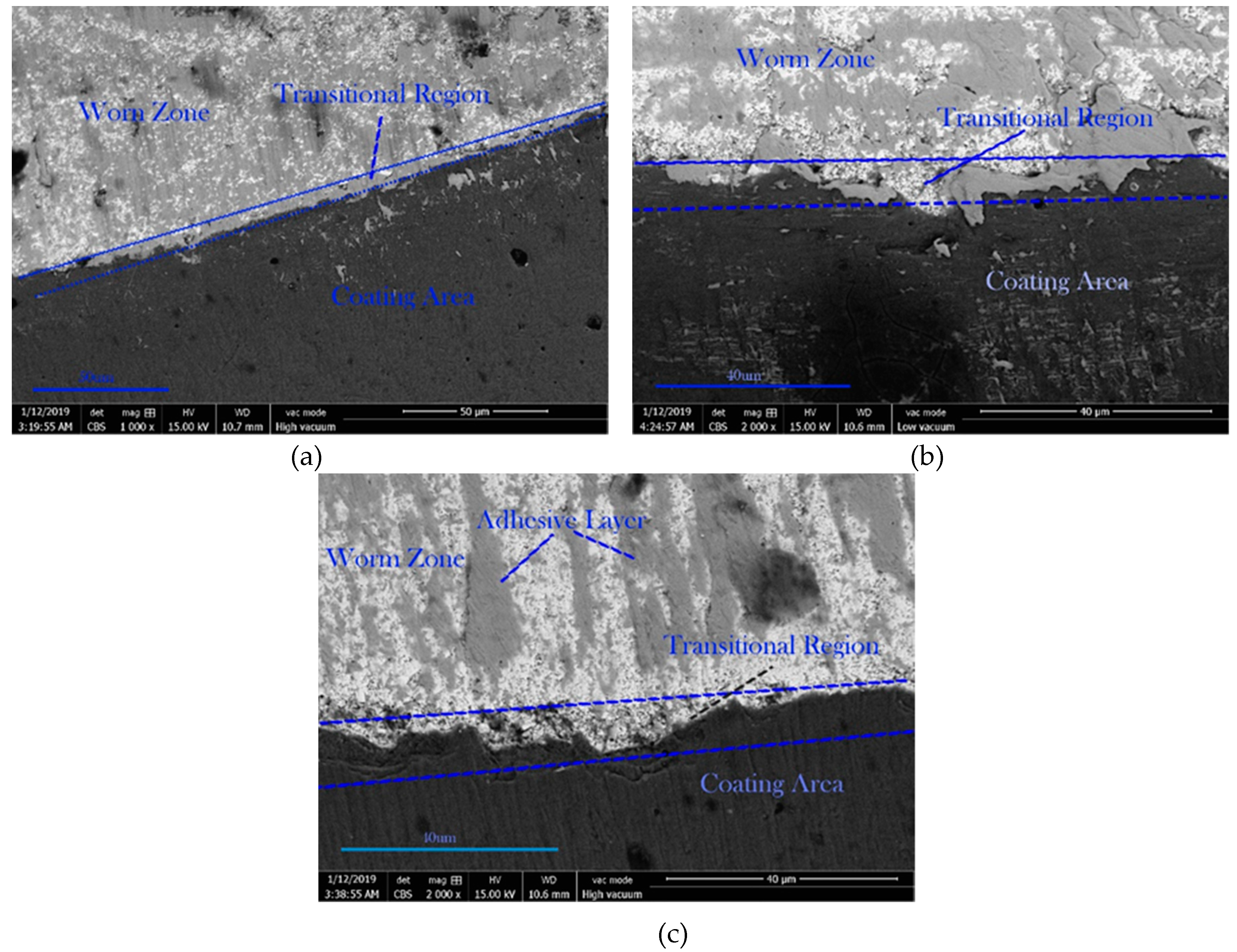
  • Four kinds of cutter surface morphology were analyzed in this paper to show the possibility of adhesive layer formation on a flank surface at cutter speeds of 150, 200, and 250 m/min, which represent three different states in the adhesive process: adhesion, shedding, and residual.
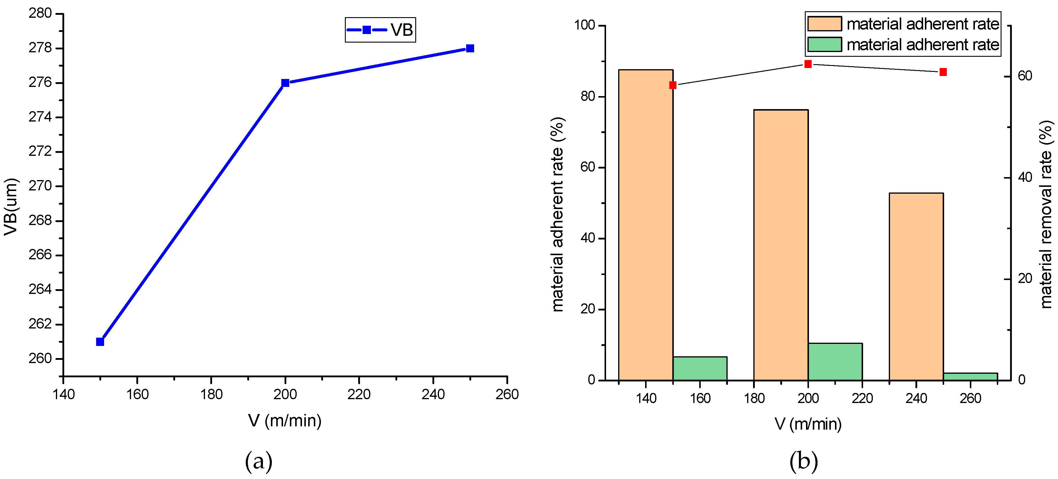
  • The cutting force parameters (based on Altintas [30]) were calculated in this paper, and the results show that the force parameters produced a relatively obvious turning point at 200 m/min. The tool geometry and its variation could be the main reason for a significant variation of milling force and tool wear.
  • Compared with tool surface composition under different cutting speeds, the adhesive layer content reached a peak value at 200 m/min. Additionally, the thermal–mechanical effect of the work-piece on a processed surface leads to serious adhesive–abrasion wear on the flank surface.
  • Under other evaluation methods (as mentioned in Figure 7 and Figure 8), the critical speed of 200 m/min is recommended, as the tool is not violently positive with the cutting speed due to transformation on the wear pattern.

Author Contributions

J.Z. proposed the basic idea for this manuscript and designed the experiment scheme to analyze the adhesive effect on tool flank wear. And he carried out the study design, analyzed and explained the data and drafted the manuscript. Y.L. and M.H. participated in the study design and preparation of the manuscript. Y.L. provides guidance on research methods, and M.H. carried out the experimental work, the data collection and interpretation.

Funding

This research was funded by the National Natural Science Foundation of China (No. 51375094) and Fuzhou Science and technology bureau (Grant No. 2018G57).

Acknowledgments

The authors would like to acknowledge the staff of Fuzhou university test center for their help.

Conflicts of Interest

The authors declare no conflict of interest.

Nomenclature

SymbolQuantity Unit
fFeed per tooth mm/z
FcCutting force in orthogonal cutting N
τShear Stress MPa
FtThrust force in orthogonal cutting N
vCutting speed m/min
F ¯ c Average cutting force in orthogonal cutting N
nSpindle rotate speed r/min
F ¯ t Average thrust force in orthogonal cutting N
apAxial depth of cut mm
FxMilling force in the X direction N
ϕShear angle deg
FyMilling force in the Y direction N
TTorsion N
FzMilling force in the Z direction N
KtxCutting parameter in the X direction
FTotal cutting force N
KrxCutting parameter in the Y direction
hCut thickness mm
KaxCutting parameter in the Z direction
bSide milling width mm
βHelical angle deg
zTooth number
DCutter diameter mm

References

  1. Yan, M.F.; Zhu, Y.D.; Zhang, C.S.; Zhang, Y.X.; Wang, Y.X.; Yang, L. Microstructure and mechanical properties of copper-titanium-nitrogen multiphase layers produced by a duplex treatment on C17200 copper-beryllium alloy. Mater. Des. 2015, 84, 10–17. [Google Scholar] [CrossRef]
  2. Sharma, A.; Datta, D.; Balasubramaniam, R. An investigation of tool and hard particle interaction in nanoscale cutting of copper beryllium. Comput. Mater. Sci. 2018, 145, 208–223. [Google Scholar]
  3. Bushlya, V.; Johansson, D.; Lenrick, F.; Ståhl, J.-E.; Schultheiss, F. Wear mechanisms of uncoated and coated cemented carbide tools in machining lead-free silicon brass. Wear 2017, 376–377, 143–151. [Google Scholar] [CrossRef]
  4. Liang, X.; Liu, Z. Tool wear behaviors and corresponding machined surface topography during high-speed machining of Ti6Al4V with fine grain tools. Tribol. Int. 2018, 121, 321–332. [Google Scholar] [CrossRef]
  5. Naskar, A.; Chattopadhyay, A.K. Investigation on flank wear mechanism of CVD and PVD hard coatings in high speed dry turning of low and high carbon steel. Wear 2018, 396–397, 98–106. [Google Scholar] [CrossRef]
  6. Sui, S.C.; Feng, P.F. The influence of tool wear on Ti6Al4V cutting temperature and burn defect. Int. J. Manuf. Technol. 2016, 85, 2831–2838. [Google Scholar] [CrossRef]
  7. Wang, C.; Ming, W.; Chen, M. Milling tool’s flank wear prediction by temperature dependent wear mechanism determination when machining Inconel 182 overlays. Tribol. Int. 2016, 104, 140–156. [Google Scholar] [CrossRef]
  8. Zheng, G.; Cheng, X.; Yang, X.; Xu, R.; Zhao, J.; Zhao, G. Self-organization wear characteristics of MTCVD-TiCN-Al2O3 coated tool against 300M steel. Ceram. Int. 2017, 43, 13214–13223. [Google Scholar] [CrossRef]
  9. Momeni, S.; Tillmann, W. Investigation of the self-healing sliding wear characteristics of NiTi-based PVD coatings on tool steel. Wear 2016, 368–369, 53–59. [Google Scholar] [CrossRef]
  10. Budak, E.; Altintas, Y. Peripheral milling conditions for improved dimensional accuracy. Int. J. Mach. Tools Manuf. 1994, 34, 907–918. [Google Scholar] [CrossRef]
  11. Shirase, K.; Altintas, Y. Cutting force and dimensional surface error generation in peripheral milling with variable pitch helical end mills. Int. J. Mach. Tools Manuf. 1996, 36, 567–584. [Google Scholar] [CrossRef]
  12. Budak, E.; Altintas, Y. Modeling and avoiding of static form errors in peripheral milling of plates. Int. J. Mach. Tools Manuf. 1995, 35, 459–476. [Google Scholar] [CrossRef]
  13. Mane, I.; Gagnol, V.; Bouzgarrou, B.C.; Ray, P. Stability-based spindle speed control during flexible workpiece high-speed milling. Int. J. Mach. Tools Manuf. 2008, 48, 184–194. [Google Scholar] [CrossRef]
  14. Vettivel, S.C.; Jegan, R.; Vignesh, J.; Suresh, S. Surface characteristics and wear depth profile of the TiN, TiAlN and AlCrN coated stainless steel in dry sliding wear condition. Surf. Interfaces 2017, 6, 1–10. [Google Scholar] [CrossRef]
  15. Pang, L.; Hosseini, A.; Hussein, H.M.; Deiab, I.; Kishawy, H.A. Application of a new thick zone model to the cutting mechanics during end-milling. Int. J. Mech. Sci. 2015, 96–97, 91–100. [Google Scholar] [CrossRef]
  16. Mia, M.; Rifat, A.; Tanvir, M.F.; Gupta, M.K.; Hossain, M.J.; Goswami, A. Multi-objective optimization of chip-tool interaction parameters using Grey-Taguchi method in MQL-assisted turning. Measurment 2018, 129, 156–166. [Google Scholar] [CrossRef]
  17. Seguy, S.; Dessein, G.; Arnaud, L. Surface roughness variation of thin wall milling, related to modal interaction. Int. J. Mach. Tools Manuf. 2008, 48, 261–274. [Google Scholar] [CrossRef]
  18. Wan, M.; Feng, J.; Ma, Y.-C.; Zhang, W.-H. Identification of milling process damping using operational modal analysis. Int. J. Mach. Tools Manuf. 2017, 122, 120–131. [Google Scholar] [CrossRef]
  19. Wan, M.; Yin, W.; Zhang, W.-H.; Liu, H. Improved inverse filter for the correction of distorted measured cutting force. Int. J. Mech. Sci. 2017, 120, 276–285. [Google Scholar] [CrossRef]
  20. Li, A.; Zhao, J.; Hou, G. Effect of cutting speed on chip formation and wear mechanisms of coated carbide tools when ultra-high-speed face milling titanium alloy Ti6-Al-4V. Adv. Mech. Eng. 2017, 9, 1–13. [Google Scholar] [CrossRef]
  21. Du, S.; Chen, M.; Xie, L.; Zhu, Z.; Wang, X. Optimization of process parameters in the high-speed milling of titanium alloy TB17 for surface integrity by the Taguchi-Grey relational analysis method. Adv. Mech. Eng. 2016, 8, 1–12. [Google Scholar] [CrossRef]
  22. Zeng, H.; Yan, R.; Du, P.; Zhang, M.; Peng, F. Notch wear prediction model in high speed milling of AerMet100 steel with bull-nose tool considering the influence of stress concentration. Wear 2018, 408–409, 228–237. [Google Scholar] [CrossRef]
  23. Heigel, J.C.; Whitenton, E.; Lane, B.; Donmez, M.A.; Madhavan, V.; Moscoso-Kingsley, W. Infrared measurement of the temperature at the tool-chip interface while machining Ti-6Al-4V. J. Mater. Process. Technol. 2017, 243, 123–130. [Google Scholar] [CrossRef]
  24. Werschmoeller, D.; Li, X. Measurement of tool internal temperatures in the tool-chip contact region by embedded micro thin film thermocouple. In Proceedings of the ASME 2010 International Manufacturing Science and Engineering Conference, Erie, PA, USA, 12–15 October 2010; pp. 371–377. [Google Scholar]
  25. An, Q.; Wang, C.; Xu, J.; Liu, P.; Chen, M. Experimental investigation on hard milling of high strength steel using PVD-AlTiN coated cemented carbide tool. Int. J. Refract. Met. Hard Mater. 2014, 43, 94–101. [Google Scholar] [CrossRef]
  26. Martinho, R.P.; Silva, F.J.G.; Martins, C.; Lopes, H. Comparative study of PVD and CVD cutting tools performance in milling of duplex stainless steel. Int. J. Adv. Manuf. Technol. 2019, 2, 1–17. [Google Scholar] [CrossRef]
  27. Huang, P.; Li, J.; Sun, J.; Ge, M. Milling force vibration analysis in high-speed-milling titanium alloy using variable pitch angle mill. Int. J. Adv. Manuf. Technol. 2012, 58, 153–160. [Google Scholar] [CrossRef]
  28. Cheng, J.; Jin, Y.; Wu, J.; Wen, X.; Gong, Y.; Shi, J.; Cai, G. Experimental study on a novel minimization method of top burr formation in micro-end milling of Ti-6Al-4V. Int. J. Adv. Manuf. Technol. 2016, 86, 2197–2217. [Google Scholar] [CrossRef]
  29. Wang, C.; Ding, F.; Tang, D.; Zheng, L.; Li, S.; Xie, Y. Modeling and simulation of the high-speed milling of hardened steel SKD11(61HRC) based on SHPB technology. Int. J. Mach. Tools Manuf. 2016, 108, 13–26. [Google Scholar] [CrossRef]
  30. Altintas, Y. Manufacturing automation: Metal cutting mechanics machine tool vibrations and CNC design; Cambridge University Press: Cambridge, UK, 2012. [Google Scholar]
  31. Cui, D.; Zhang, D.; Wu, B.; Luo, M. An investigation of tool temperature in end milling considering the flank wear effect. Int. J. Mech. Sci. 2017, 131–132, 613–624. [Google Scholar] [CrossRef]
  32. Wan, M.; Ma, Y.-C.; Feng, J.; Zhang, W.-H. Study of static and dynamic ploughing mechanisms by establishing generalized model with static milling force. Int. J. Mech. Sci. 2016, 114, 120–131. [Google Scholar] [CrossRef]
  33. Fillot, N.; Iordanoff, I.; Berthier, Y. Modelling third body flows with a discrete element method—a tool for understanding wear with adhesive particles. Tribol. Int. 2007, 40, 973–981. [Google Scholar] [CrossRef]
  34. Aramesh, M.; Montazeri, S.; Vedhuis, S.C. A novel treatment for cutting tools for reducing the chipping and improving tool life durning machining of Inconel 718. Wear 2018, 414–415, 79–88. [Google Scholar] [CrossRef]
Figure 1. Machining center and test platform.
Metals 09 00444 g001
Figure 2. Sticking substance and adhesive wear. (a) adhesive morphology; (b) residual form of the adhesion; (c) single-point adhesive wear; (d) mixed wear pattern.
Metals 09 00444 g002
Figure 3. Tool wear patterns. (a) tool wear pattern at 150 m/min cutting speed; (b) Tool wear pattern at 200 m/min cutting speed; (c) Tool wear pattern at 250 m/min cutting speed.
Metals 09 00444 g003
Figure 4. Relationship between element content and processing speed. (a) Adherence rate; (b) basic resin.
Metals 09 00444 g004
Figure 5. Linear parameter calibration. (a) The ka was calibrated at the cutting speed of 150 m/min; (b) The ka was calibrated at the cutting speed of 200 m/min; (c) The ka was calibrated at the cutting speed of 250 m/min; (d) The kr was calibrated at the cutting speed of 150 m/min; (e) The kr was calibrated at the cutting speed of 200 m/min; (f) The kr was calibrated at the cutting speed of 250 m/min; (g) The kt was calibrated at the cutting speed of 150 m/min; (h) The kt was calibrated at the cutting speed of 200 m/min; (i) The kt was calibrated at the cutting speed of 250 m/min.
Metals 09 00444 g005aMetals 09 00444 g005b
Figure 6. The trend of decomposition stress. (a) The parameter Kac varies with the cutting speed; (b) The parameter Kae varies with the cutting speed; (c) The parameter Krc varies with the cutting speed; (d) The parameter Kre varies with the cutting speed; (e) The parameter Ktc varies with the cutting speed; (f) The parameter Kte varies with the cutting speed.
Metals 09 00444 g006
Figure 7. Back-scattered electron imaging. (a) The coating condition of the tool surface at 150 m/min; (b) The coating condition of the tool surface at 200 m/min; (c) The coating condition of the tool surface at 250 m/min.
Metals 09 00444 g007
Figure 8. Wear and tool surface conditions. (a) Tool wear with cutting speed; (b) material adhesion rate and removal rate.
Metals 09 00444 g008
Table 1. Chemical composition and mechanical properties of C17200.
Contents (wt.%)Material Properties
BeCoNiSiFeAlCuTensile Strength MPaHardness HRCYield Strength GPa
1.90.350.200.150.150.15Bal110538–44128
Table 2. Cutting parameters of the multi-factor orthogonal experiment.
V = 150 m/minV = 200 m/minV = 250 m/min
f/(mm·r−1)ap/mmf/(mm·r−1)ap/mmf/(mm·r−1)ap/mm
0.050.50.050.50.050.5
0.110.110.11
0.151.50.151.50.151.5

