Characterization of 14Cr ODS Steel Fabricated by Spark Plasma Sintering


Abstract
:1. Introduction
2. Experiment
3. Results and Discussion
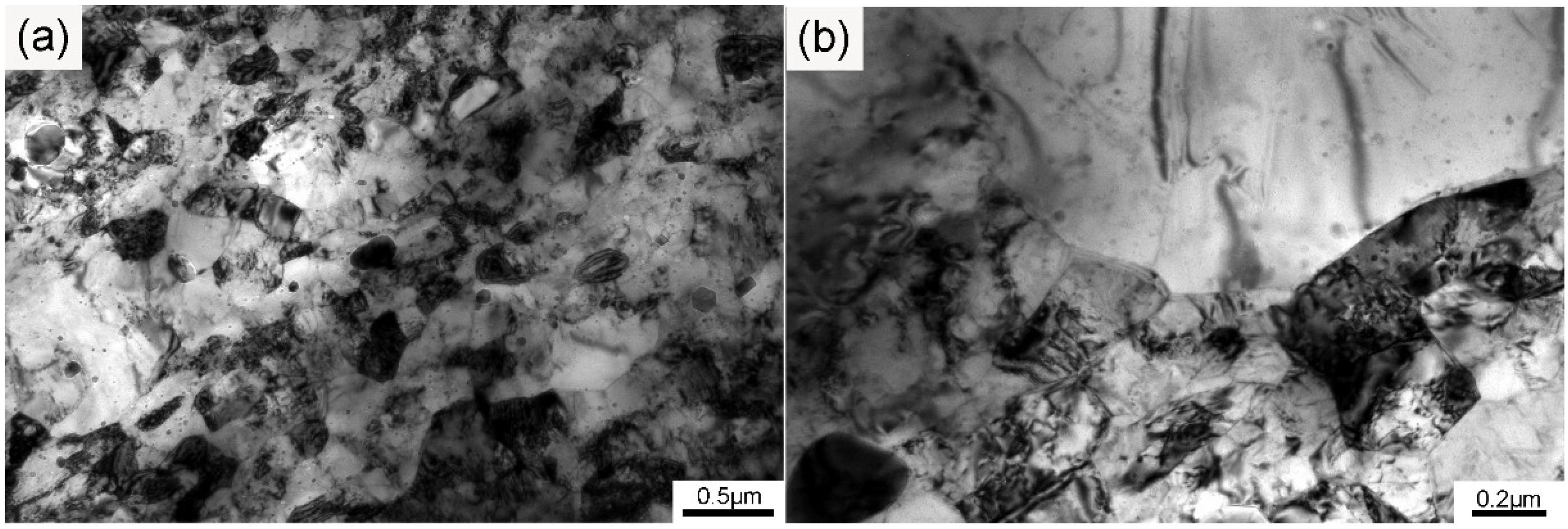
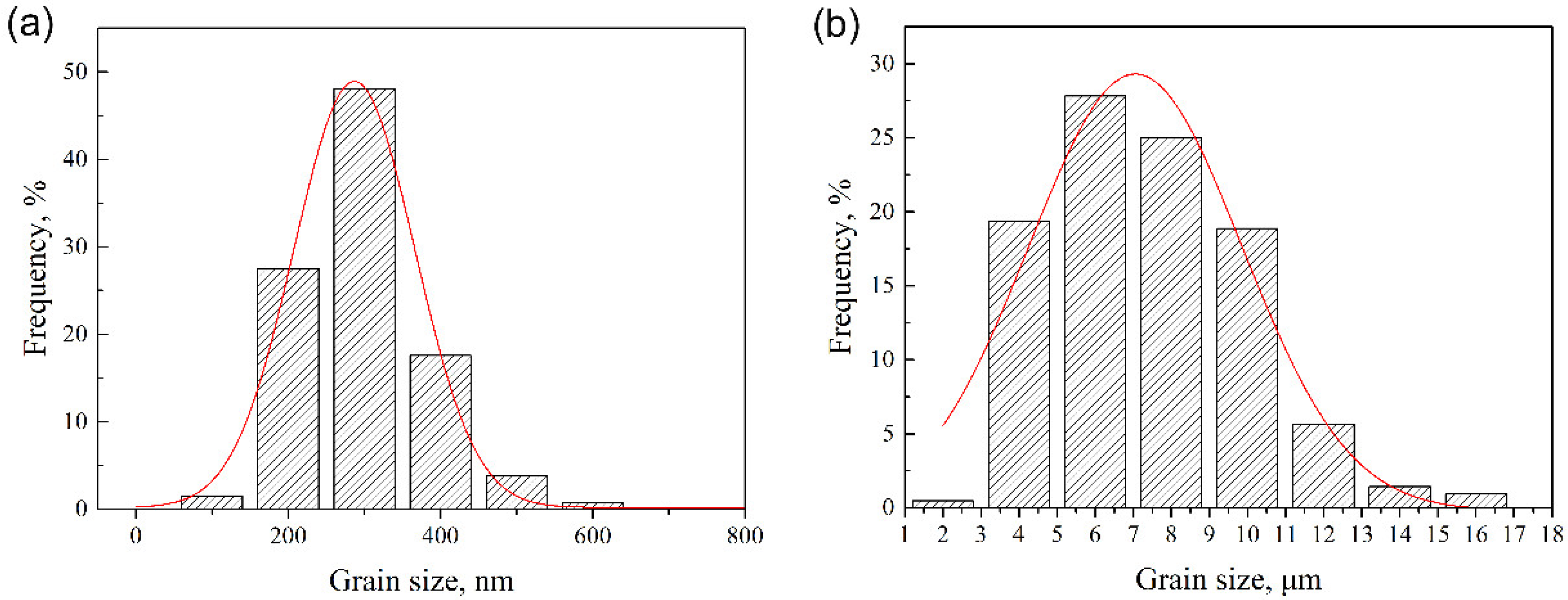
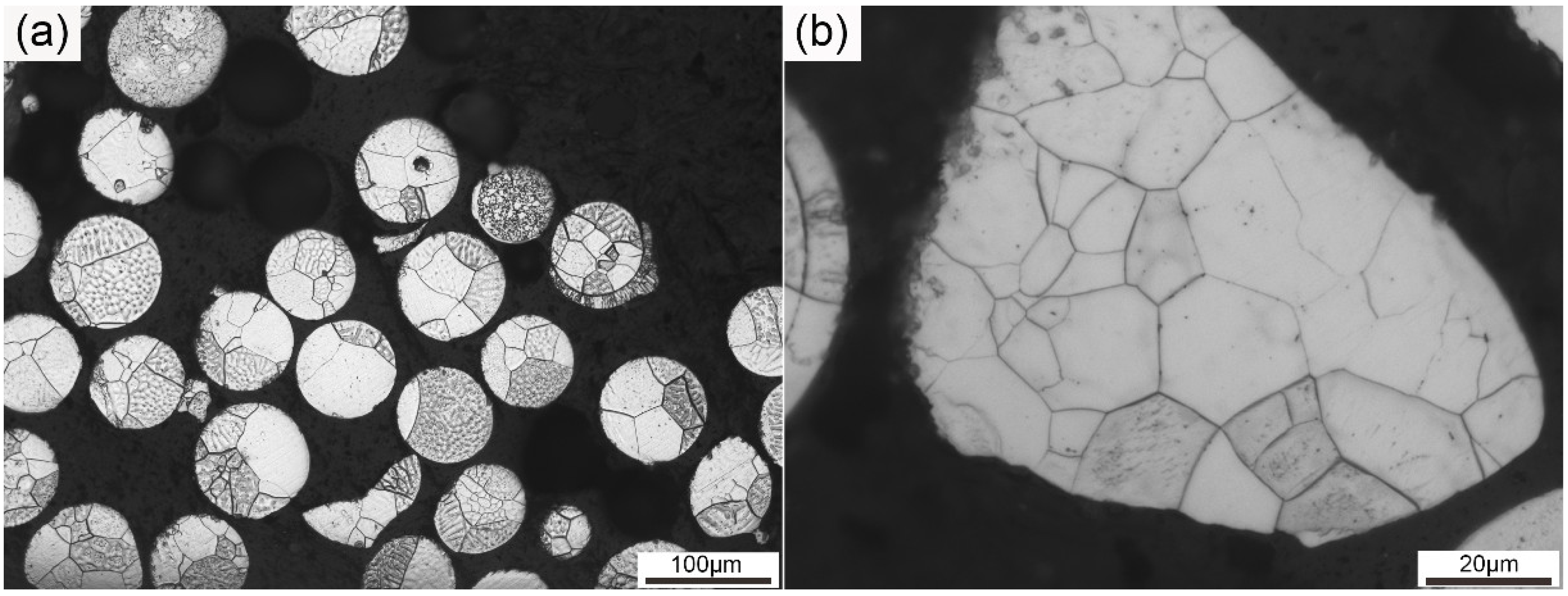
3.1. Microstructure
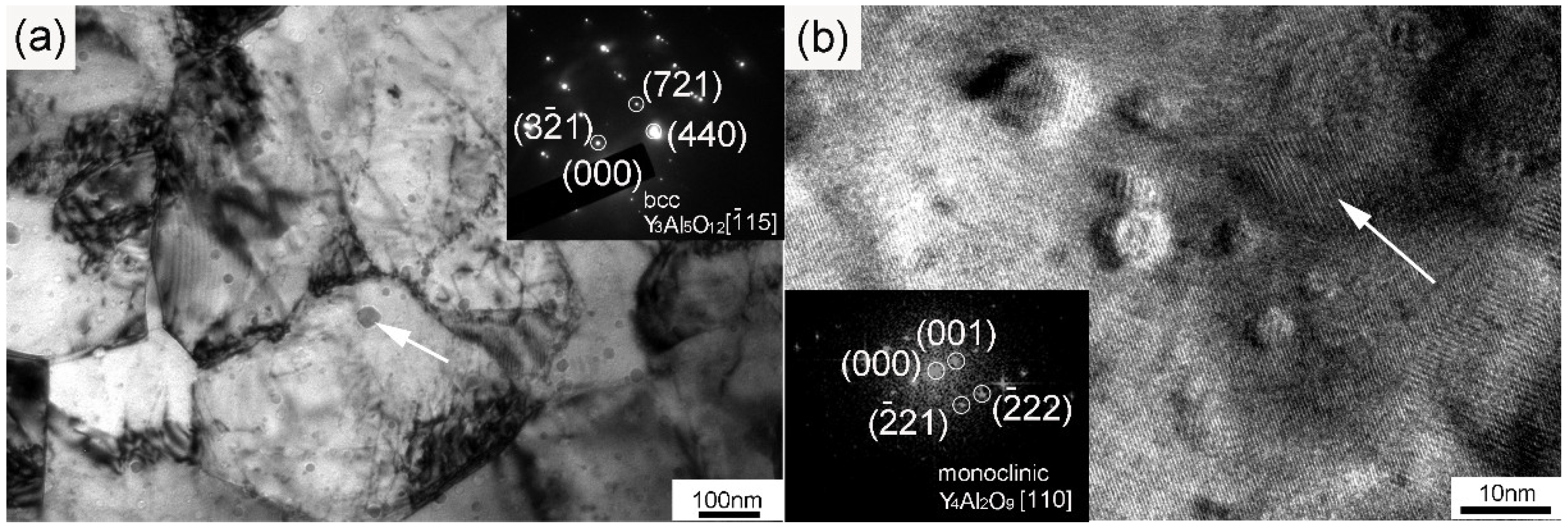
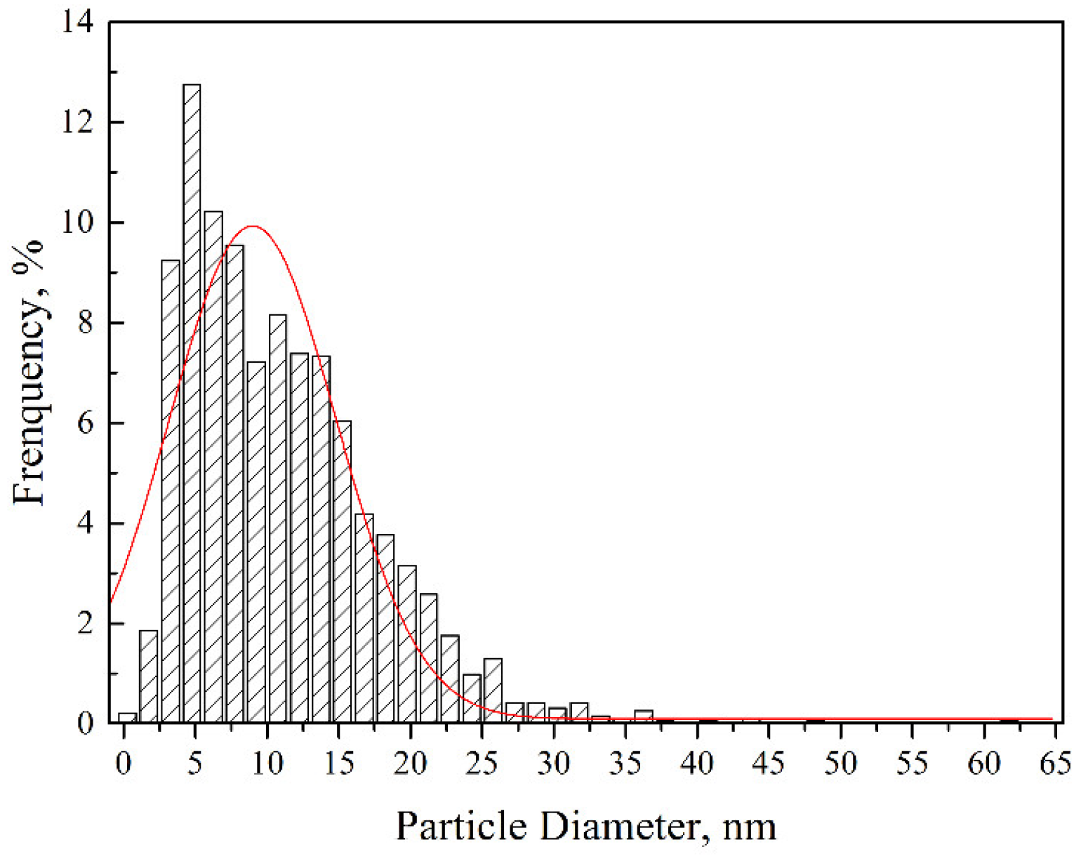
3.2. Nanoparticles
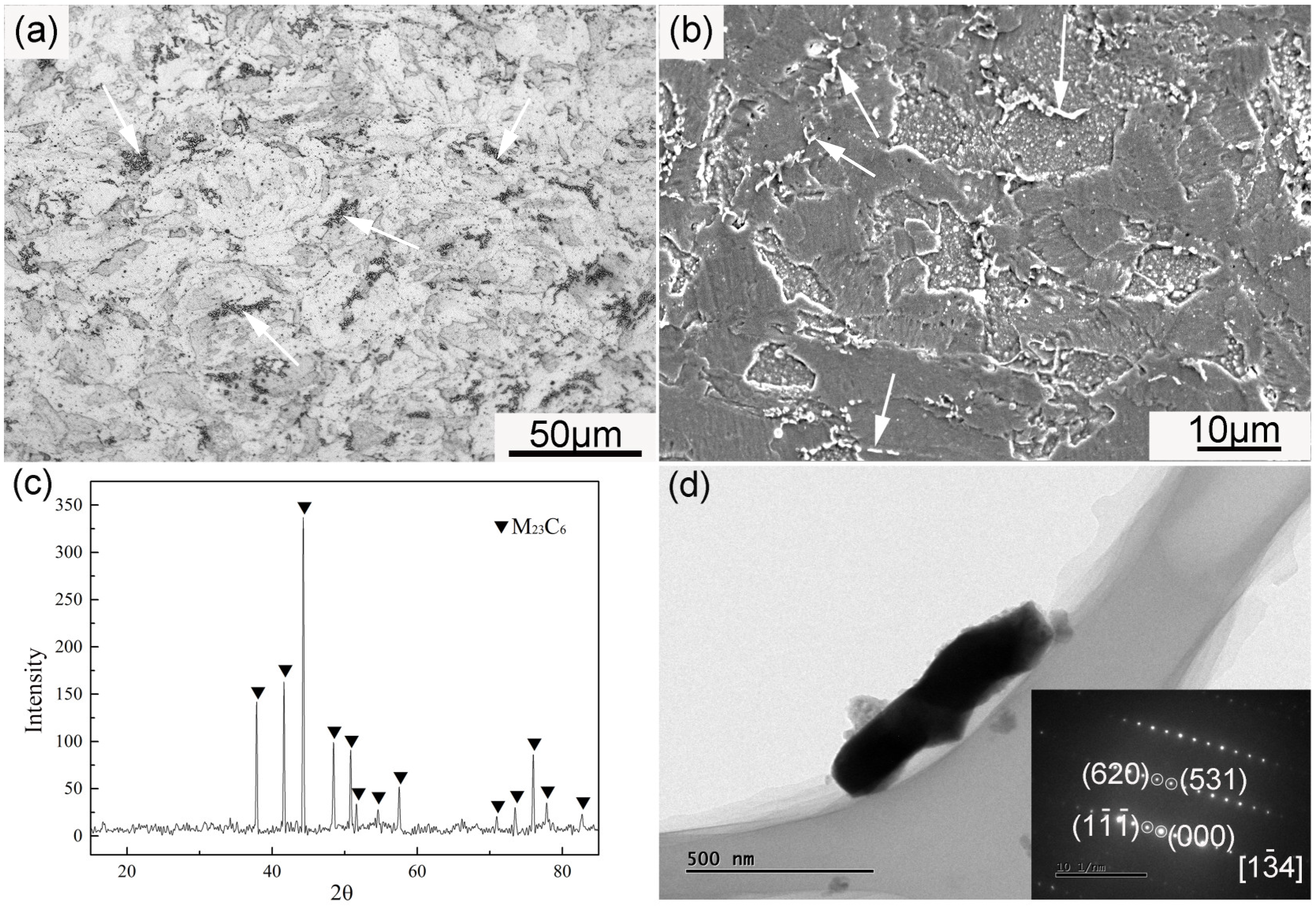
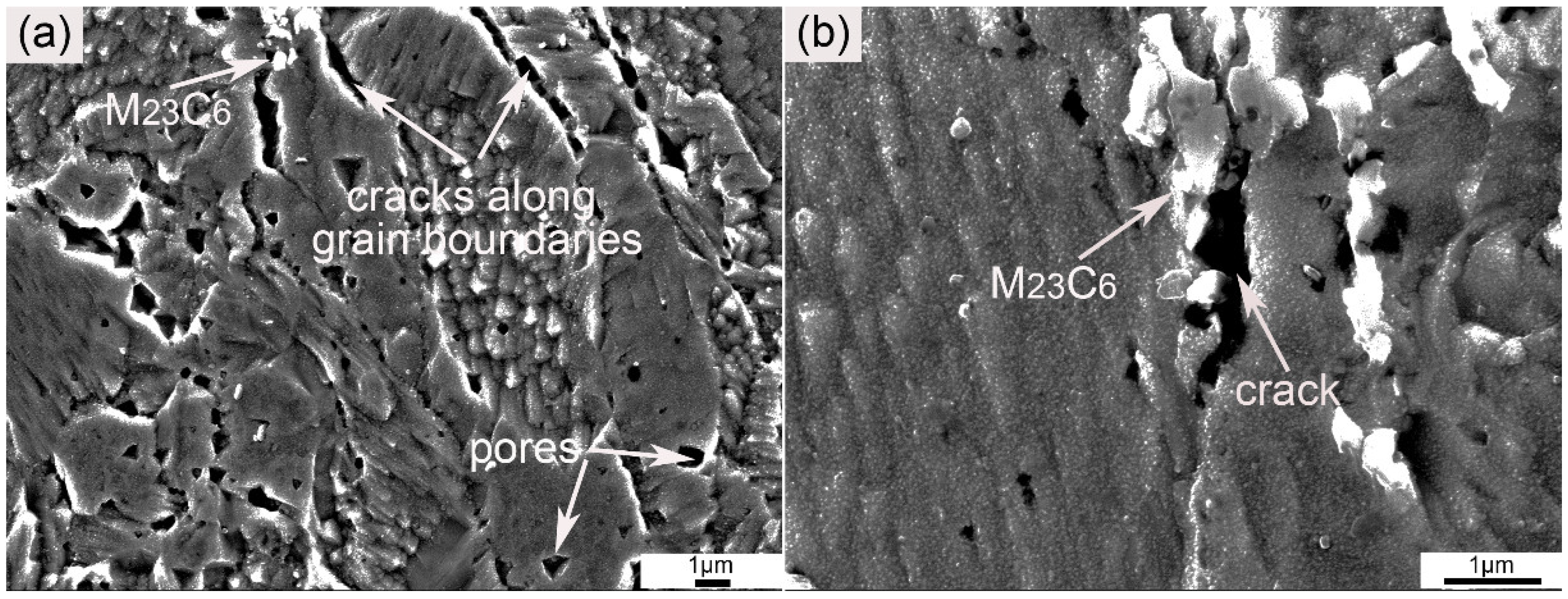
3.3. M23C6
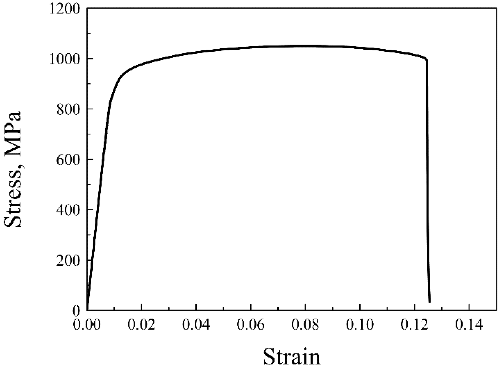
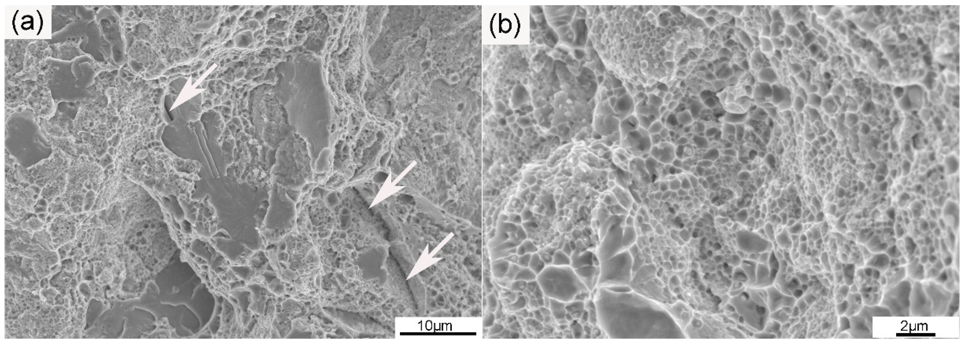
3.4. Tensile Properties
4. Conclusions
- (1)
- Both submicron-sized and micron-sized grains existed in the microstructure of the as-SPSed ODS sample;
- (2)
- Body-centered cubic Y3Al5O12 particles and monoclinic Y4Al2O9 particles were identified, and these nanoparticles were found homogeneously distributed in the ODS sample;
- (3)
- The existence of large M23C6 particles in the ODS sample was confirmed;
- (4)
- Tensile properties of the as-SPSed ODS sample were analyzed, and the fracture mode was predominantly ductile with regions of brittle fracture.
Author Contributions
Funding
Conflicts of Interest
References
- Klueh, R.L. Elevated temperature ferritic and martensitic steels and their application to future nuclear reactors. Int. Mater. Rev. 2005, 50, 287–310. [Google Scholar] [CrossRef]
- Mao, C.; Liu, C.; Yu, L.; Li, H.; Liu, Y. The correlation among microstructural parameter and dynamic strain aging (DSA) in influencing the mechanical properties of a reduced activated ferritic-martensitic (RAFM) steel. Mater. Sci. Eng. A 2019, 739, 90–98. [Google Scholar] [CrossRef]
- Zhou, Y.; Liu, Y.; Zhou, X.; Liu, C.; Yu, J.; Huang, Y.; Li, H.; Li, W. Precipitation and hot deformation behavior of austenitic heat-resistant steels: A review. J. Mater. Sci. Technol. 2017, 33, 1448–1456. [Google Scholar] [CrossRef]
- Wharry, J.P.; Swenson, M.J.; Yano, K.H. A review of the irradiation evolution of dispersed oxide nanoparticles in the bcc Fe-Cr system: Current understanding and future directions. J. Nucl. Mater. 2017, 486, 11–20. [Google Scholar] [CrossRef]
- Odette, G.R. On the status and prospects for nanostructured ferritic alloys for nuclear fission and fusion application with emphasis on the underlying science. Scr. Mater. 2018, 143, 142–148. [Google Scholar] [CrossRef]
- Zhang, C.; Cui, L.; Wang, D.; Liu, Y.; Liu, C.; Li, H. The heterogeneous microstructure of heat affect zone and its effect on creep resistance for friction stir joints on 9Cr–1.5W heat resistant steel. Scr. Mater. 2019, 158, 6–10. [Google Scholar] [CrossRef]
- Nguyen, S.T.; Nakayama, T.; Suematsu, H.; Suzuki, T.; Nanko, M.; Cho, H.B.; Huynh, M.T.T.; Jiang, W.H.; Niihara, K. Synthesis of molten-metal corrosion resistant yttria-based refractory by hot-pressing and densification. J. Eur. Ceram. Soc. 2015, 35, 2651–2662. [Google Scholar] [CrossRef]
- Hilger, I.; Boulnat, X.; Hoffmann, J.; Testani, C.; Bergner, F.; De Carlan, Y.; Ferraro, F.; Ulbricht, A. Fabrication and characterization of oxide dispersion strengthened (ODS) 14Cr steels consolidated by means of hot isostatic pressing, hot extrusion and spark plasma sintering. J. Nucl. Mater. 2016, 472, 206–214. [Google Scholar] [CrossRef]
- Auger, M.A.; De Castro, V.; Leguey, T.; Muñoz, A.; Pareja, R. Microstructure and mechanical behavior of ODS and non-ODS Fe–14Cr model alloys produced by spark plasma sintering. J. Nucl. Mater. 2013, 436, 68–75. [Google Scholar] [CrossRef]
- Zhou, X.; Liu, Y.; Yu, L.; Ma, Z.; Guo, Q.; Huang, Y.; Li, H. Microstructure characteristic and mechanical property of transformable 9Cr-ODS steel fabricated by spark plasma sintering. Mater. Des. 2017, 132, 158–169. [Google Scholar] [CrossRef]
- Chauhan, A.; Bergner, F.; Etienne, A.; Aktaa, J.; De Carlan, Y.; Heintze, C.; Litvinov, D.; Hernandez-Mayoral, M.; Oñorbe, E.; Radiguet, B.; et al. Microstructure characterization and strengthening mechanisms of oxide dispersion strengthened (ODS) Fe-9% Cr and Fe-14% Cr extruded bars. J. Nucl. Mater. 2017, 495, 6–19. [Google Scholar] [CrossRef]
- Nagini, M.; Vijay, R.; Rajulapati, K.V.; Reddy, A.V.; Sundararajan, G. Microstructure–mechanical property correlation in oxide dispersion strengthened 18Cr ferritic steel. Mater. Sci. Eng. A 2017, 708, 451–459. [Google Scholar] [CrossRef]
- Abbasi, S.M.; Shokuhfar, A. Improvement of Mechanical Properties of Cr-Ni-Mo-Cu-Ti Stainless Steel with Addition of Vanadium. J. Iron Steel Res. Int. 2007, 14, 74–78. [Google Scholar] [CrossRef]
- Rogozhkin, S.V.; Aleev, A.A.; Zaluzhnyi, A.G.; Nikitin, A.A.; Iskandarov, N.A.; Vladimirov, P.; Lindau, R.; Möslang, A. Atom probe characterization of nano-scaled features in irradiated ODS Eurofer steel. J. Nucl. Mater. 2011, 409, 94–99. [Google Scholar] [CrossRef]
- Oksiuta, Z.; Lewandowska, M.; Kurzydlowski, K.J.; Baluc, N. Effect of vanadium addition on the microstructure and mechanical properties of the ODS ferritic steels. J. Nucl. Mater. 2013, 442, S84–S88. [Google Scholar] [CrossRef]
- Klueh, R.L.; Alexander, D.J.; Sokolov, M.A. Effect of chromium, tungsten, tantalum, and boron on mechanical properties of 5–9Cr–WVTaB steels. J. Nucl. Mater. 2002, 304, 139–152. [Google Scholar] [CrossRef]
- Chen, J.; Liu, Y.; Liu, C.; Yan, B.; Li, H. Effects of tantalum on austenitic transformation kinetics of RAFM steel. J. Iron Steel Res. Int. 2017, 24, 705–710. [Google Scholar] [CrossRef]
- Rahmanifard, R.; Farhangi, H.; Novinrooz, A.J. Development of mechanical performance of 12YWT steel nanocomposite by addition of zirconium and tantalum. J. Alloys Compd. 2016, 657, 646–654. [Google Scholar] [CrossRef]
- Kimura, A.; Kasada, R.; Iwata, N.; Kishimoto, H.; Zhang, C.H.; Isselin, J.; Dou, P.; Lee, J.H.; Muthukumar, N.; Okuda, T.; et al. Development of Al added high-Cr ODS steels for fuel cladding of next generation nuclear systems. J. Nucl. Mater. 2011, 417, 176–179. [Google Scholar] [CrossRef]
- Li, S.F.; Zhou, Z.J.; Wang, P.H.; Sun, H.Y.; Wang, M.; Zhang, G.M. Long-term thermal-aging stability of a 16Cr-oxide dispersion strengthened ferritic steel at 973 K. Mater. Des. 2016, 90, 318–329. [Google Scholar] [CrossRef]
- Dou, P.; Kimura, A.; Kasada, R.; Okuda, T.; Inoue, M.; Ukai, S.; Ohnuki, S.; Fujisawa, T.; Abe, F. TEM and HRTEM study of oxide particles in an Al-alloyed high-Cr oxide dispersion strengthened steel with Zr addition. J. Nucl. Mater. 2014, 444, 441–453. [Google Scholar] [CrossRef]
- Zhao, Q.; Yu, L.M.; Liu, Y.C.; Huang, Y.; Guo, Q.Y.; Li, H.J.; Wu, J.F. Evolution of Al-containing phases in ODS steel by hot pressing and annealing. Powder Technol. 2017, 311, 449–455. [Google Scholar] [CrossRef]
- Li, W.; Hao, T.; Gao, R.; Wang, X.; Zhang, T.; Fang, Q.; Liu, C. The effect of Zr, Ti addition on the particle size and microstructure evolution of yttria nanoparticle in ODS steel. Powder Technol. 2017, 319, 172–182. [Google Scholar] [CrossRef]
- Xie, R.; Lu, Z.; Lu, C.; Li, Z.; Ding, X.; Liu, C. Microstructures and mechanical properties of 9Cr oxide dispersion strengthened steel produced by spark plasma sintering. Fusion Eng. Des. 2017, 115, 67–73. [Google Scholar] [CrossRef]
- Mao, X.; Oh, K.H.; Jang, J. Evolution of ultrafine grained microstructure and nano-sized semi-coherent oxide particles in austenitic oxide dispersion strengthened steel. Mater. Charact. 2016, 117, 91–98. [Google Scholar] [CrossRef]
- Dou, P.; Kimura, A.; Kasada, R.; Okuda, T.; Inoue, M.; Ukai, S.; Ohnuki, S.; Fujisawa, T.; Abe, F.; Jiang, S.; Yang, Z. TEM and HRTEM study of oxide particles in an Al-alloyed high-Cr oxide dispersion strengthened ferritic steel with Hf addition. J. Nucl. Mater. 2017, 485, 189–201. [Google Scholar] [CrossRef]
- Ohtsuka, S.; Ukai, S.; Fujiwara, M.; Kaito, T.; Narita, T. Nano-structure control in ODS martensitic steels by means of selecting titanium and oxygen contents. J. Phys. Chem. Solids 2005, 66, 571–575. [Google Scholar] [CrossRef]
- He, P.; Klimenkov, M.; Lindau, R.; Möslang, A. Characterization of precipitates in nano structured 14% Cr ODS alloys for fusion application. J. Nucl. Mater. 2012, 428, 131–138. [Google Scholar] [CrossRef]
- Hoelzer, D.T.; Unocic, K.A.; Sokolov, M.A.; Byun, T.S. Influence of processing on the microstructure and mechanical properties of 14YWT. J. Nucl. Mater. 2016, 471, 251–265. [Google Scholar] [CrossRef]
- Burke, K.E. Chemical extraction of refractory inclusions from iron-and nickel-base alloys. Metallography 1975, 8, 473–488. [Google Scholar] [CrossRef]
- Gao, R.; Xia, L.L.; Zhang, T.; Wang, X.P.; Fang, Q.F.; Liu, C.S. Oxidation resistance in LBE and air and tensile properties of ODS ferritic steels containing Al/Zr elements. J. Nucl. Mater. 2014, 455, 407–411. [Google Scholar] [CrossRef]
- Zhang, Z.; Orlov, D.; Vajpai, S.K.; Tong, B.; Ameyama, K. Importance of bimodal structure topology in the control of mechanical properties of a stainless steel. Adv. Eng. Mater. 2015, 17, 791–795. [Google Scholar] [CrossRef]
- Pande, C.S.; Cooper, K.P. Nanomechanics of Hall–Petch relationship in nanocrystalline materials. Prog. Mater. Sci. 2009, 54, 689–706. [Google Scholar] [CrossRef]
- Ramtani, S.; Dirras, G.; Bui, H.Q. A bimodal bulk ultra-fine-grained nickel: Experimental and micromechanical investigations. Mech. Mater. 2010, 42, 522–536. [Google Scholar] [CrossRef]
- Magee, A.; Ladani, L.; Topping, T.D.; Lavernia, E.J. Effects of tensile test parameters on the mechanical properties of a bimodal Al–Mg alloy. Acta Mater. 2012, 60, 5838–5849. [Google Scholar] [CrossRef]
- Oliera, P.; Couvrat, M.; Cayrond, C.; Lochet, N.; Chaffron, L. Incidence of mechanical alloying contamination on oxides and carbides formation in ODS ferritic steels. J. Nucl. Mater. 2013, 442, s106–s111. [Google Scholar] [CrossRef]
- Nagini, M.; Vijay, R.; Ramakrishna, M.; Reddy, A.V.; Sundararajan, G. Influence of the duration of high energy ball milling on the microstructure and mechanical properties of a 9Cr oxide dispersion strengthened ferritic–martensitic steel. Mater. Sci. Eng. A 2017, 620, 490–499. [Google Scholar] [CrossRef]
- Liu, T.; Shen, H.; Wang, C.; Chou, W. Microstructure and mechanical properties of Al containing ODS ferritic alloys by VHP and HIP. Mater. Res. Innov. 2015, 18, 410–413. [Google Scholar] [CrossRef]
- Li, S.; Zhou, Z.; Li, M.; Wang, M.; Zhang, G. Microstructure characterization and tensile properties of 18Cr–4Al-oxide dispersion strengthened ferritic steel. J. Alloys Compd. 2015, 648, 39–45. [Google Scholar] [CrossRef]
- Li, M.; Zhou, Z.; He, P.; Xu, Y.; Liao, L. Annealing behavior of 12-Cr based mechanical alloyed oxide dispersion strengthened ferritic alloys. J. Nucl. Mater. 2011, 417, 189–192. [Google Scholar] [CrossRef]


© 2019 by the authors. Licensee MDPI, Basel, Switzerland. This article is an open access article distributed under the terms and conditions of the Creative Commons Attribution (CC BY) license (http://creativecommons.org/licenses/by/4.0/).
Share and Cite
Zhao, Q.; Qiao, Z.; Liu, Y.; Yu, L.; Huang, Y.; Guo, Q.; Li, H. Characterization of 14Cr ODS Steel Fabricated by Spark Plasma Sintering. Metals 2019, 9, 200. https://doi.org/10.3390/met9020200
Zhao Q, Qiao Z, Liu Y, Yu L, Huang Y, Guo Q, Li H. Characterization of 14Cr ODS Steel Fabricated by Spark Plasma Sintering. Metals. 2019; 9(2):200. https://doi.org/10.3390/met9020200
Chicago/Turabian StyleZhao, Qian, Zhixia Qiao, Yongchang Liu, Liming Yu, Yuan Huang, Qianying Guo, and Huijun Li. 2019. "Characterization of 14Cr ODS Steel Fabricated by Spark Plasma Sintering" Metals 9, no. 2: 200. https://doi.org/10.3390/met9020200
APA StyleZhao, Q., Qiao, Z., Liu, Y., Yu, L., Huang, Y., Guo, Q., & Li, H. (2019). Characterization of 14Cr ODS Steel Fabricated by Spark Plasma Sintering. Metals, 9(2), 200. https://doi.org/10.3390/met9020200