Abstract
An innovative, high-strength metal–intermetallic-laminate (MIL) composite Ti-(SiCf/Al3Ti), reinforced by double or even several SiC fiber rows, was fabricated. A high-efficiency, semi-analytical model with a numerical equivalent inclusion method (NEIM) was employed to investigate the deformation behaviors, microscopic strengthening, and failure mechanisms of the composite during elasto-plastic sphere–plane contact. The microstructure and interface features were characterized by scanning electron microscopy (SEM) and energy dispersive spectrometer (EDS). The contact model for the Ti-(SiCf/Al3Ti) composite was validated via quasi-static compressive indentation tests with a spherical indenter. A series of in-depth parametric studies were conducted to quantify the effect of the microstructure. The results indicate that the as-fabricated laminated composite has a well-organized microstructure and a higher volume fraction of fibers. The SiC fiber rows effectively enhance the strength and toughness of the composite. The optimal diameter of the SiC fibers is 32 μm when the horizontal center distance between the adjacent fibers is 2.5 times that of the fiber diameter. The hole defects occurring above the fibers would damage the material strength most compared with those occurring in other positions. The optimal quantity of the SiC fiber rows is four when the thickness of the SiCf/Al3Ti layer is 400 μm and the fiber diameter is 8 μm.
1. Introduction
In the mid-1990s, it was discovered that the superior mechanical performance of a shell is closely related to its special ductile–brittle laminated structure. In the light of this, a novel Ti-Al3Ti composite, which is a metal–intermetallic-laminated composite (MIL) with laminated components of ductile metallic titanium (Ti) layers and brittle intermetallic Al3Ti layers, was devised by researchers [1,2,3]. Tests showed that the abovementioned laminated composite possesses a fivefold fracture toughness compared with the intermetallic compound Al3Ti, and moreover, its superior properties, such as low density, high strength, and stiffness, meet the performance demands for the structural components of an aircraft engine. Furthermore, the MIL composite possesses a high energy absorption capability due to its special failure mode, so it has a wide range of potential applications in the armor protection field [4]. So far, the developed strengthening and toughening methods for MIL composites not only include layer reinforcement, but also extend to particle [5] and fiber [6] reinforcement techniques, by which the room-temperature plasticity of the intermetallic compound is improved to some extent. Given that, to study the Ti-Al3Ti-laminated composite and its strengthening–toughening methods is of great scientific significance.
Previous studies have indicated that the brittle, intermetallic layers still exhibit characteristics of low plasticity, which restrict the overall performance of the composite material. In the last few years, owing to the combination of fiber reinforcement and the laminated composite joining technique or, more specifically, introducing SiC ceramic fibers with superior performance into the intermetallic layer, the laminated composite material of Ti-(SiCf/Al3Ti) has been developed. The plastic property of brittle layers in this material has been enhanced, which has improved the mechanical performance of the overall MIL composite [7]. Furthermore, by setting double or even several SiC fiber rows into a single Al3Ti layer during the sintering preparation process with the foil–fiber–foil method (FFF) [8], the quantity and volume fraction of SiC fibers in the Ti-(SiCf/Al3Ti)-laminated composite have been increased considerably. Thus, the constraint that a high fiber volume fraction requires high thickness of the Al3Ti layer for the Ti-(SiCf/Al3Ti) composite reinforced by a single SiC fiber row has been subtly eliminated. Moreover, due to the simple preparation process, the strength and toughness of the as-fabricated material have been further improved significantly. However, with the microstructure forms of the fiber-reinforced MIL composites becoming more and more diverse, it is important to find an effective and efficient approach to investigate the connection between the microstructure and the mechanical properties.
In recent years, the basic mechanical properties of fiber-reinforced Ti/Ti-Al-laminated composites in various series have been researched by many scholars at home and abroad via multi-angle mechanics experiments. Yu and Zhu [9,10] at Tsinghua University fabricated a fiber-reinforced laminated composite containing a Ti–Al alloy layer reinforced by SiC monofilament fibers. Through compressive and bending tests, they proved that the mechanical properties of fiber-reinforced laminated composites are superior to that of single-phase intermetallic compounds or laminated composites without fiber reinforcement. Li et al. [11,12,13] conducted compressive mechanical tests for Ti-Al3Ti-laminated composites with different Ti volume fractions (14%, 20%, and 35%) under various loading conditions, such as different loading directions (perpendicular and parallel to the laminated layers) and loading rates (with strain rate 0.0001/s and 800~2000/s), as well as strain magnitudes (1%, 2%, and 3%). Based on the test results, they investigated the crack propagation path and damage evolvement process; meanwhile, the strengthening and toughening mechanism of the laminated composites was also analyzed. Raghavendra et al. [14,15] studied the influence of the thickness and volume fraction of the ductile layers on the fracture toughness and fatigue crack growth of Ti-Al3Ti-laminated composites, presenting that the “bridge-connection” action of the Ti layers can enormously enhance the toughness and fatigue resistance of Ti-Al3Ti composites, far above those of the single-phase intermetallic compound Al3Ti. Vecchio et al. [16] at the University of California, San Diego first studied and fabricated the laminated composite Ti-Al3Ti-Al-Al2O3 with bunchy Al2O3 fiber reinforcements and conducted fracture toughness tests and toughening mechanism analysis on the composite. The test results indicated that the introduction of Al2O3 fibers can dramatically improve the toughness of laminated composites as well. However, there are inherent drawbacks when employing mechanical property tests on material samples to research fiber-reinforced laminated composites. Given that a lot of microstructure parameters of composites cannot be controlled precisely during the sintering process, such as the thickness of the layers or the distance between the two adjacent fibers in one row, most of the comparative property tests cannot be carried out based on the rigorous control variate method. In addition, the cost of mechanical tests on material specimens is relatively high.
With the rise of the numerical simulation method, the experimental cost has reduced significantly, which has promoted the development of microstructure-related variable-controlling experiments on MIL composites. Thereby, more and more scholars have utilized a numerical modeling method to investigate the mechanical properties of fiber-reinforced Ti-Al-laminated composites. For instance, Cao et al. [17] adopted ANSYS to numerically simulate the fracture behavior of Ti/Al3Ti-laminated composite under a dynamic bending load. A typical scalariform failure mode was observed during the cracking process of Ti/Al3Ti-laminated composite, suggesting that the damage tolerance of such MIL composites is very high. Tsartsaris et al. [18] simulated a glass-based fiber-reinforced MIL composite to investigate its low velocity impact response with LSDYNA 3D finite element method (FEM). They concluded that the dominant shear stress within the material is higher than the tensile or compressive stresses, and the metal layers stacked in the middle absorb less energy than the ones placed at the two ends. Most of the current numerical algorithms are based on a FEM, which is suitable to deal with complex situations owing to its flexibility and versatility. Nevertheless, when it comes to the three-dimensional (3D) contact problems, a very large solution domain (at least 10 times the contact region in each dimension) is required. Additionally, a very fine mesh is required. As a result, the computational efforts are very large and the execution efficiency is very low. In contrast, a semi-analytical method (SAM) does not require a large solution domain [19,20]. Because it is based on an analytical core solution, instead of using the nodes on the boundary of each mesh, a SAM calculates the mechanical responses at central points of each mesh. Thus, a SAM is more convenient to solve contact problems, especially when implementing the strategy of the equivalent inclusion method (EIM) presented by Eshelby [21]. EIM transforms an inhomogeneity problem into an inclusion problem coupled with properly given eigenstrain. However, the uniform eigenstrain assumption in EIM is only applicable to solve the inhomogeneous materials with ellipsoidal inclusions, which seriously limits the applications of EIM. Zhou et al. [22] proposed a numerical equivalent inclusion method (NEIM) based on the full-space cuboidal inclusion solution of Chiu [23] and the mirror superposition method [24]. The NEIM is capable of solving elastic fields of a two-dimensional (2D) full space containing irregular-shaped inhomogeneities, which considerably expand the application scope of traditional EIM. However, in the field of fiber-reinforced laminated composite material, the application of this high-efficiency numerical method is rather rare.
The main aim of this work is to numerically simulate the elasto-plastic contact of SiC fiber-reinforced MIL composite material and investigate its deformation behaviors, microscopic strengthening, and failure mechanisms during the sphere–plane loading process. To this end, a vacuum hot-pressing sintering method was adopted to fabricate a novel Ti-(SiCf/Al3Ti) composite with double-layered SiC fiber reinforcements. The microstructure and interface characterization of the presented composite were performed using scanning election microscope (SEM) and energy dispersive spectrometer (EDS). Then, the elasto-plastic sphere–plane contact model was built based on the combination of a semi-analytical model, which was proposed by Liu [20], and a numerical equivalent inclusion method. 2D and 3D fast Fourier transform (FFT) were applied during the solving process to boost the computational efficiency. The accuracy and feasibility of the proposed model for the Ti-(SiCf/Al3Ti) composite was validated via quasi-static compressive indentation tests under a spherical indenter. Furthermore, a serious of parametric studies were conducted to quantify the influence of the microstructure on the mechanical properties and optimize the structural design of the Ti-(SiCf/Al3Ti) composite material.
2. Fabrication of Ti-(SiCf/Al3Ti)-Laminated Composite with Double-Layered SiC Fiber Reinforcements
As well known, the fibers would be ultimately located in the central part of the intermetallic layer during the fabrication process of the Ti-(SiCf/Al3Ti)-laminated composite via the foil–fiber–foil method [25]. This particular formation characteristic results in a severe limitation to the volume fraction of fibers in laminated composites. The only way to increase the volume fraction of SiC fibers in the Ti-(SiCf/Al3Ti)-laminated composite is to reduce the thickness of the foils, namely, employing thin foil sintering fabrication.
In this work, an innovative Ti-Al3Ti-laminated composite Ti-(SiCf/Al3Ti) with double or even several rows of SiC fibers coexisting in a single Al3Ti layer was devised and fabricated. The quantity and volume fraction of the SiC fibers in the proposed composite were increased significantly, while the thickness of the foils was not reduced, for the purpose of enhancing the strength of the composite.
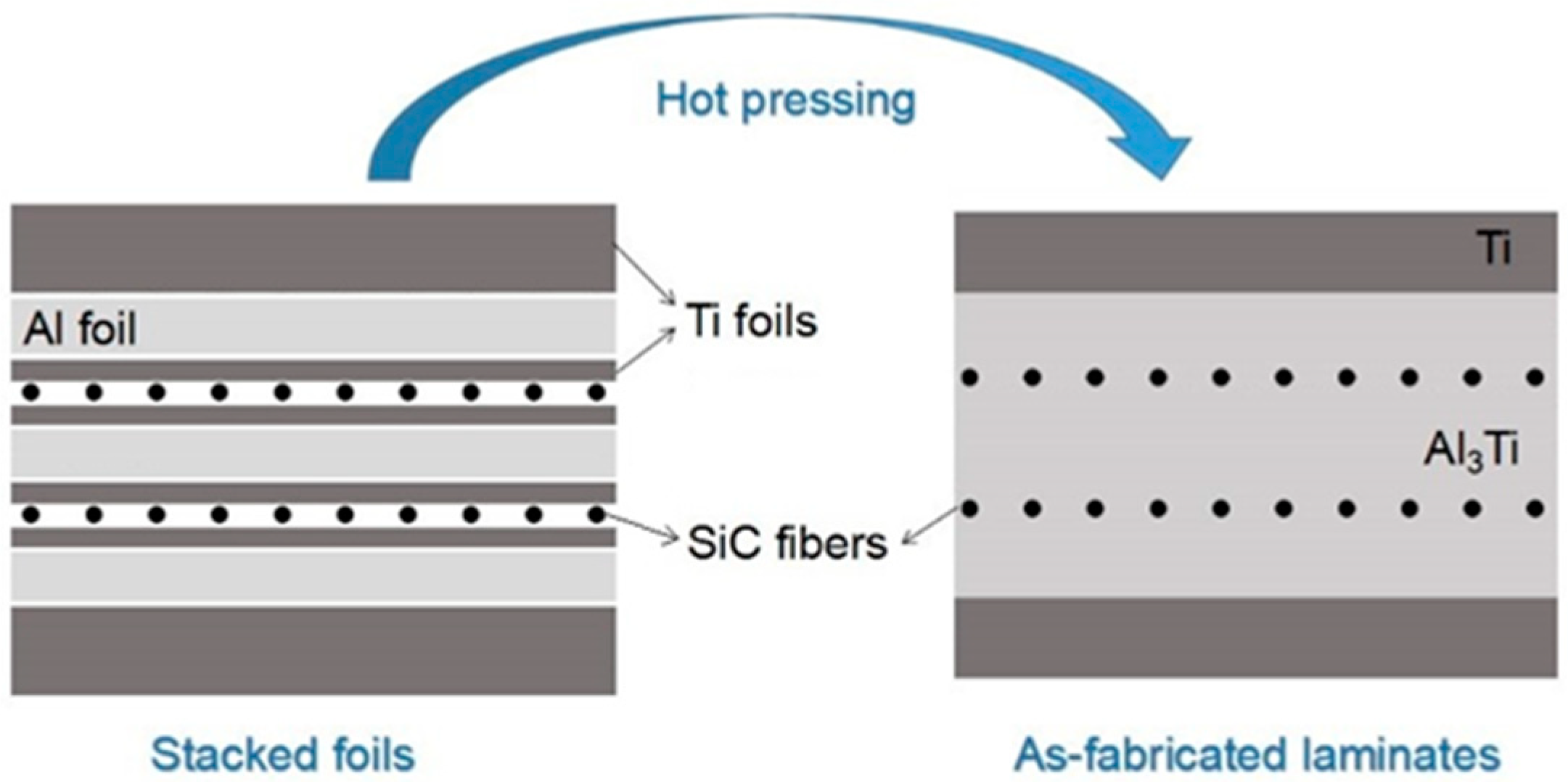
Utilizing thin titanium (Ti-6Al-4V) foils, about 100 μm thick, as the barrier layers of raw materials, the foils and fibers were stacked in an order of “Ti-Al-Ti-SiCf-Ti-Al-Ti-SiCf-Ti-Al-Ti”, which was defined as one basic “unit”. The stack order of the original component materials and the microstructure of the as-fabricated laminated composite are illustrated in Figure 1. It can be seen that two thin Ti foils were employed to isolate the SiC fibers from the Al foils when preparing the composite, which helped to prevent contact between SiC and the oxide on the surface of the Al foils. As a result, the fibers in the prepared Ti-(SiCf/Al3Ti)-laminated composite cannot contact the “centerline”, thereby avoiding the disturbance of the “centerline” to the SiCf/Al3Ti interface, for the purpose of obtaining a Ti-(SiCf/Al3Ti)-laminated composite with tightly bonded interfaces, a well-organized microstructure, and superior overall performance. It should point out that the so-called “centerline” is a discontinuous interface consisting of a number of tiny voids or cracks located in the central part of the intermetallic layer, which is mainly attributed to the oxides on the surface of the Al foils having difficulty in diffusing or metallurgical bonding with the intermetallic compounds during the sintering process [26].
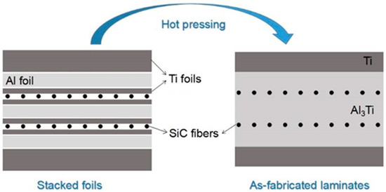
Figure 1.
Schematic illustration of the fabrication process of the Ti-(SiCf/Al3Ti)-laminated composite using a Ti barrier layer.
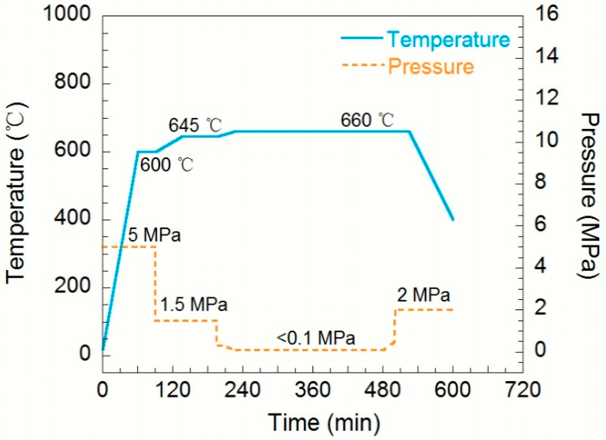
A vacuum hot-pressed sintering technique with Ti barrier layers was adopted to fabricate the Ti-(SiCf/Al3Ti)-laminated composite, and the bonding process between the SiC fibers and the intermetallic compound Al3Ti was optimized by adjusting the sintering parameters of sintering temperature and loading pressure, which were applied to the stack. The optimized parameter curves for the vacuum hot-pressed sintering process are displayed in Figure 2.
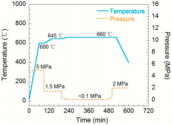
Figure 2.
Processing parameters for fabricating the Ti-(SiCf/Al3Ti)-laminated composite via vacuum hot pressing.
After the sintering process, the microstructure characterization was performed by scanning electron microscopy (SEM, Hitachi SU-70, HITACHI, Tokyo, Japan) coupled with energy dispersive spectroscopy (EDS, XFlash Detector 6|60, BRUKER, Karlsruhe, Germany) in order to observe the volume fraction of each component and the microstructure of the reaction interfaces.
3. Numerical Equivalent Inclusion Method
3.1. 3D Semi-Analytical Model Description
In this paper, the contact between the Ti-(SiCf/Al3Ti) composite and a rigid spherical indenter was investigated; thus, a three-dimensional model was employed. A number of models could have been applied in this work, including but not limited to a finite element method (FEM) or a semi-analytical model (SAM). Compared with a FEM, a SAM shows a great efficiency advantage when tackling contact problems of inhomogeneous materials without losing any result accuracy [27]. Therefore, the calculations were performed by a proposed SAM, whose detailed solution procedure is described in [28].
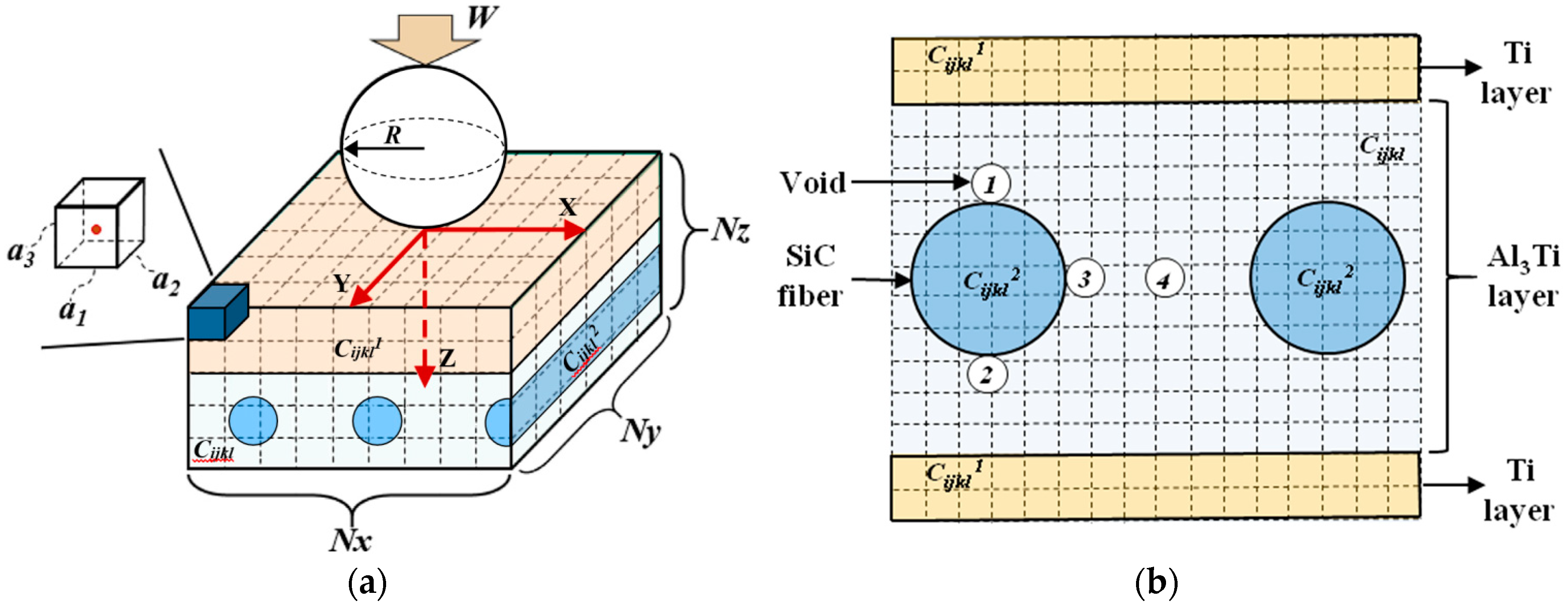
In a SAM, as shown in Figure 3a [29], the computational domain is bounded by a Cartesian coordinate system, where the x and y axis are parallel to the surface of the half space and the z axis points to depth direction. The origin, O, of the coordinate system is superposed with the contact point, which is also the initial loading point applied by the rigid spherical indenter. The entire calculation zone, including both the inhomogeneities and matrix materials, is discretized into Nx × Ny × Nz cubic elements. The element at the top left corner of the half space in Figure 3a [29] is magnified to display the definition of an element by its edges, a1, a2, and a3. A concentrated loading force, W, is applied on a spherical rigid indenter whose radius is R. The material properties of each element are assigned according to the core location, whether in the inhomogeneities or the matrix. Therefore, for the inhomogeneous material of the Ti-(SiCf/Al3Ti) composite in this paper, as shown in Figure 3a [29], the material model mainly contains the Al3Ti matrix, layered inhomogeneities of Ti layers, and columnar inhomogeneities of SiC fibers. The elastic coefficients of the Al3Ti matrix and the Ti and SiC inhomogeneities are , , and , respectively. Additionally, the defect factor-like voids around the SiC fibers can also be taken into account. Figure 3b is the magnified schematic diagram for the cross section of the material model considering the hole defects around the SiC fibers. According to the SEM images in previous works [6,25,30], the locations where voids usually occur can be summarized into four typical places around the SiC fibers, as shown in Figure 3b. Correspondingly, the elastic coefficient of voids is 0.
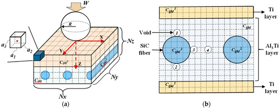
Figure 3.
Schematic diagram of the semi-analytical model for the inhomogeneous material of the Ti-(SiCf/Al3Ti) composite: (a) basic contact model containing a layered inhomogeneity of Ti layer and multiple cylindrical inhomogeneities of SiC fibers [29]; (b) magnified cross section of the material model considering the hole defects around the SiC fibers.
3.2. 3D Half-Space Numerical Equivalent Inclusion Method
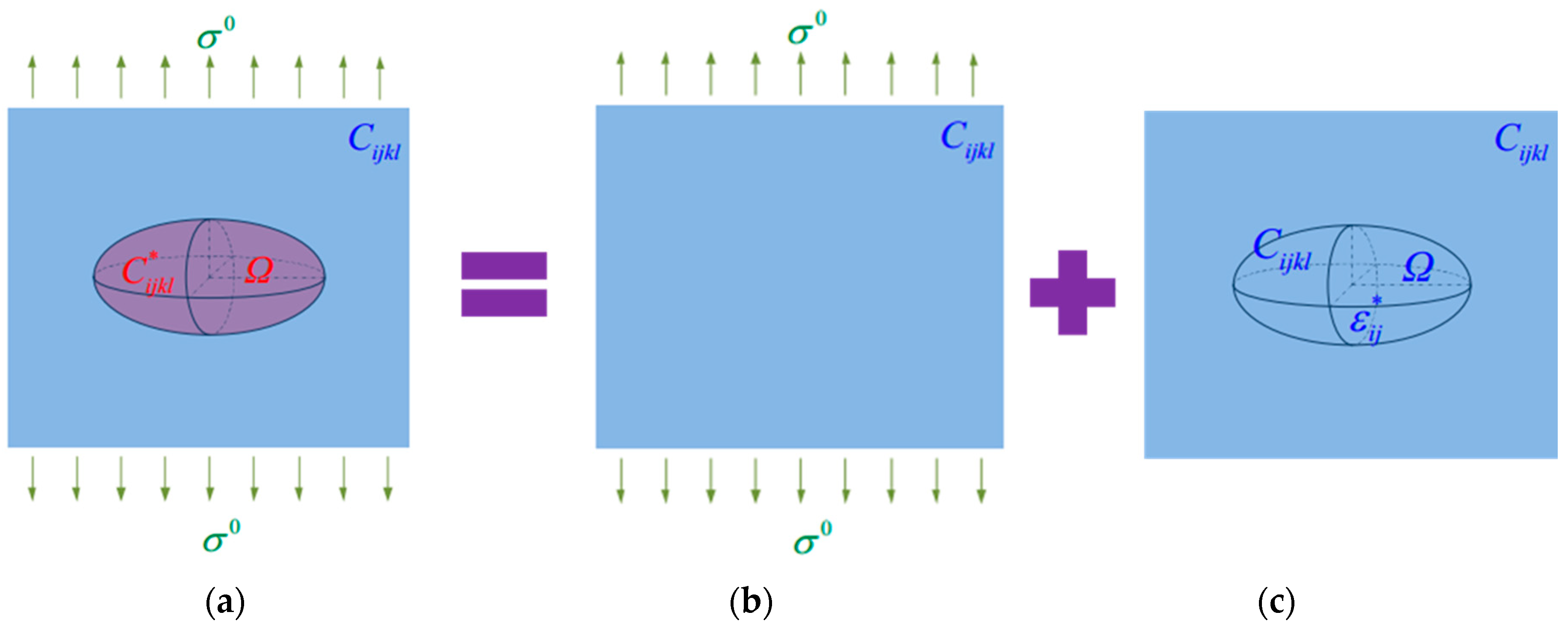
According to the basic idea of EIM, the elastic disturbance of an inhomogeneity (in this case, a SiC fiber reinforcement) in a 3D half-space to the matrix material, as shown in Figure 4a, can be equivalently substituted by two parts of solutions, which are (1) the half-space homogeneous solution under the contact load, as shown in Figure 4, and (2) the half-space inclusion solution with certain assigned eigenstrains, as shown in Figure 4c. To put it another way, it is essentially converting an inhomogeneity problem into an inclusion problem coupled with properly assigned eigenstrains. Compared with an inhomogeneity whose properties are different than those of the matrix material, an inclusion is a region whose properties are the same as those of a matrix material except that it contains a certain number of eigenstrains. An eigenstrain is a generic name defined by Mura [31] to refer to the localized, tiny, non-elastic strain in a body that is free from any other external force and surface constraint, such as thermal expansion or plastic strain.
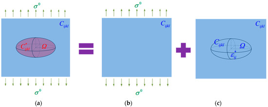
Figure 4.
(a) The disturbance of an inhomogeneity to the matrix can be substituted by the superposition of (b) a homogeneous solution without inhomogeneity and (c) an equivalent inclusion solution with properly assigned eigenstrains.
The consistency condition of EIM can be expressed as follows:
where is the initial strain generated by the contact load, which can be solved by Hertz’s solution; is the strain disturbance induced by inhomogeneity (or fiber reinforcement in this case); and is the eigenstrain distributed in the equivalent inclusion [32]. The relationship between the strain disturbance and eigenstrain is , in which is Eshelby tensor, and therefore, eigenstrain is the only unknown variable needed to be solved. Given that the computational domain is separated into Nx × Ny × Nz cubic elements and contains n (n ≤ Nx × Ny × Nz) inhomogeneity elements, the governing equation in Equation (1) is built for each inhomogeneity element. The strain at the jth equivalent inclusion element is the superposition of strain contributions from all the inclusion elements, which is as follows:
where is the Eshelby tensor associating the eigenstrain of the ith inclusion element with the strain disturbance of the jth inclusion element. Corresponding to the arbitrarily shaped inhomogeneity comprised by n cubic elements, n similar equations such as Equation (2) can be combined to build simultaneous equations. Therefore, the eigenstrain distribution of inclusions in the computational domain involving the interaction among each equivalent inclusion element can be solved.
The numerical equivalent inclusion methodology (NEIM) can handle the inhomogeneity issues with arbitrary shape and distribution by means of numerical discretization, which breaks through the limit of traditional EIM, which can only deal with regular ellipsoidal or elliptical inhomogeneities. During the process of solving simultaneous equations, the conjugate gradient method (CGM) was adopted to solve the linear equations in Equation (2). Compared with general methods to solve linear equations such as the Gaussian elimination method, the CGM can boost the solution efficiency enormously. More details about the CGM are described in [33].
The strain disturbance at an arbitrary element in the matrix material is the superposition of strain contributions from all the equivalent inclusion elements in the computational domain, which is as follows:
where , , , and are the influence coefficients associating eigenstrain and strain disturbance, which are detailed in [20]. It is worth noting that the first item on the right side of Equation (3) is the convolution between eigenstrains along the x, y, z directions and the influence coefficients, and the other three items are the convolutions between two variables along the x and y directions, while along the z direction, they are the correlation operations between eigenstrains and influence coefficients. Therefore, for the first item, 3D discrete convolution and FFT (3D DC-FFT) [20,34] can be adopted to accelerate computation. Correspondingly, the other three items can employ 3D discrete convolution—discrete correlation and FFT (3D DC-DCR-FFT) [35,36]—to accelerate computation.
3.3. Plasticity Consideration
In the proposed model, the materials of the inhomogeneities and the matrix can both be set as elasto-plastic. The plasticity-related parameters of the inhomogeneities and the matrix are different, such as the yield strength or work hardening parameters. In this section, all the theories and algorithms discussed are applicable to both the inhomogeneities and the matrix. Accordingly, the parameters mentioned below do not need to be distinguished.
Considering the work hardening issue, the isotropic hardening following the Swift law is adopted in the proposed model to describe the growing yield strength [37].
where is the yield strength, B, c, and n are the work hardening parameters related to the material properties, and is the effective accumulative plastic strain, which is expressed as .
The yield condition is identified by the Von Mises yield criterion. The total Von Mises stress can be obtained by superimposing the elastic stress , residual stress , and eigenstress induced by the inhomogeneities, expressed as . The yield function is as follows:
where is the deviatoric stress.
As is well known, the material yields when , for example, when the Von Mises stress is larger than the current yield limit of the material. Additionally, a new balance is reached if the increment of the effective accumulative plastic strain meets the condition of , where is the plastic strain increment. A universal integration algorithm developed by Fotiu and Nemat-Nasser [38] and further improved by Nélias et al. [39] is applied to calculate the value of in each load step. Finally, the plastic strain increment can be obtained by means of the plastic flow rule:
According to the theory proposed by Jacq et al. [40], the surface residual displacement can be expressed as follows based on the reciprocal theorem:
Furthermore, the residual stresses , can be solved by superposing the disturbances of all the yield regions with a non-zero plastic strain. The residual stress can be obtained by treating the plastic strains as eigenstrains [20] through Equation (3).
3.4. Numerical Algorithm Implementation Procedure
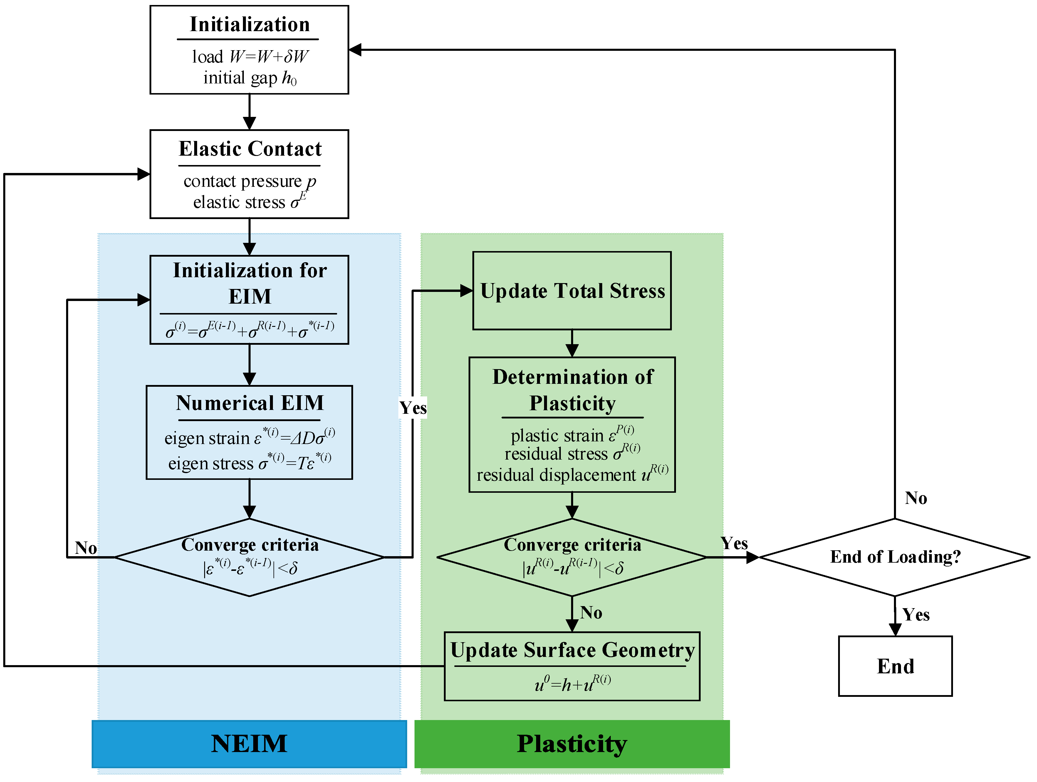
Figure 5 indicates the overall scheme of the numerical algorithm to solve for the contact of the elasto-plastic inhomogeneous materials, which contains two main iterations: the NEIM and the plasticity loops. The NEIM loop, based on the iterative method developed by Zhang et al. [41], is applied to determine the equivalent eigenstrains and corresponding eigenstresses. The plasticity loop, which is also part of the algorithm proposed by Jacq et al. [40], is utilized to calculate the plastic strains, residual stresses, and surface residual displacements.

Figure 5.
Flow chart of the algorithm for solving the inhomogeneous contact elasto-plastic issues. EIM: equivalent inclusion method; NEIM: numerical equivalent inclusion method.
A total of four procedures need to be conducted when solving the current model: First, to determine the contact pressure between the spherical indenter and the half-space material; second, to calculate the elastic stress field beneath the surface by means of 2D-FFT after the contact pressure is determined; third, to solve the eigenstress induced by the inhomogeneities; and fourth, to evaluate the plastic strain and residual stress fields of the computational domain and also the residual displacement on the surface, which can update the surface topography for the new iteration until the convergence condition is fulfilled. It should be pointed out that the coefficient matrix of the EIM consistency equation is ill-conditioned when the inhomogeneities are voids or too soft. Therefore, the step factor of the CGM should be reduced appropriately in order to improve the convergence property under such conditions.
The typical results of the current numerical model include the equivalent plastic strain, total Von Mises stress, residual Von Mises stress, contact pressure, and surface residual displacement, which can comprehensively reveal the mechanical behaviors and properties of the inhomogeneous material during the loading process. Therefore, the current SAM model is capable of providing various results that satisfy the requirements of this work.
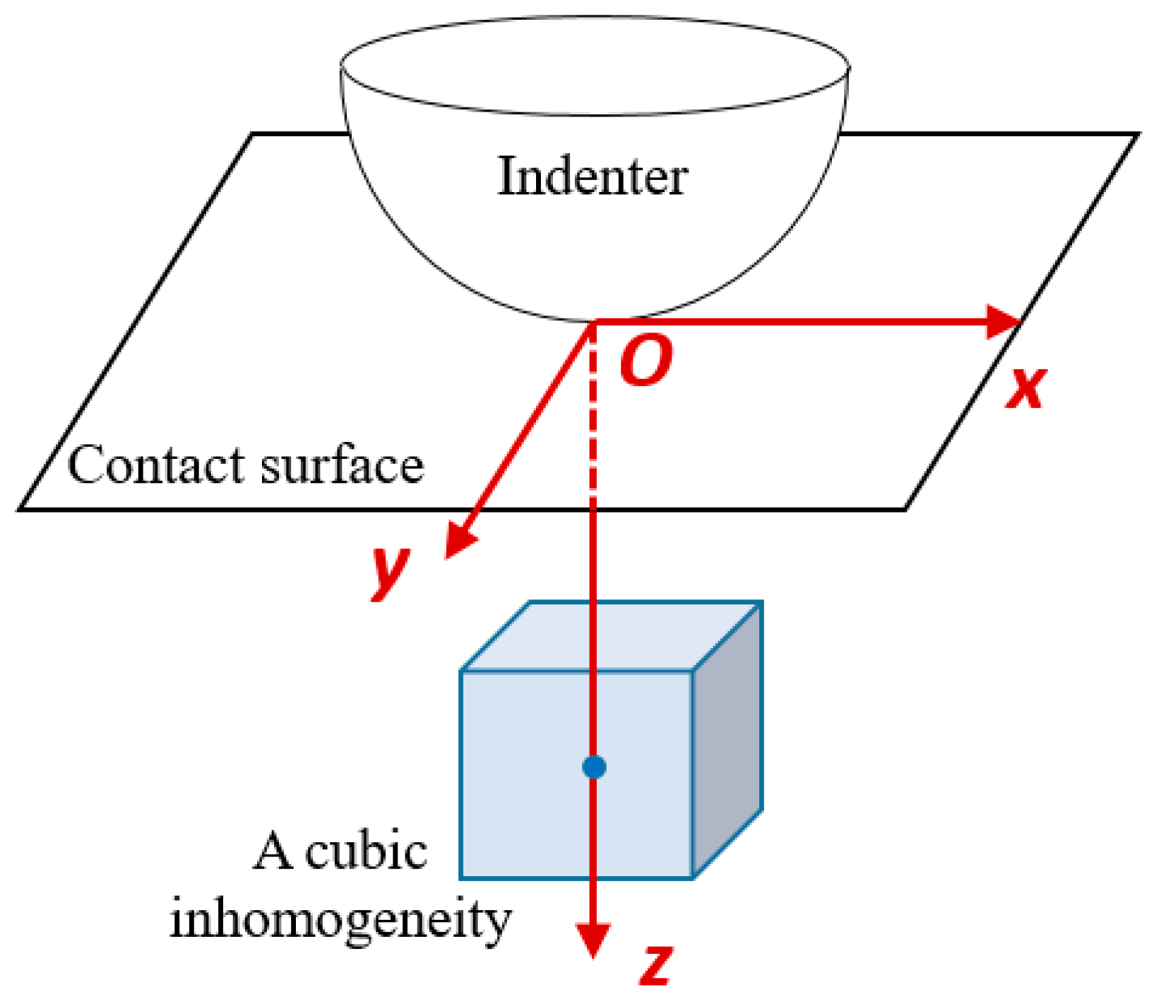
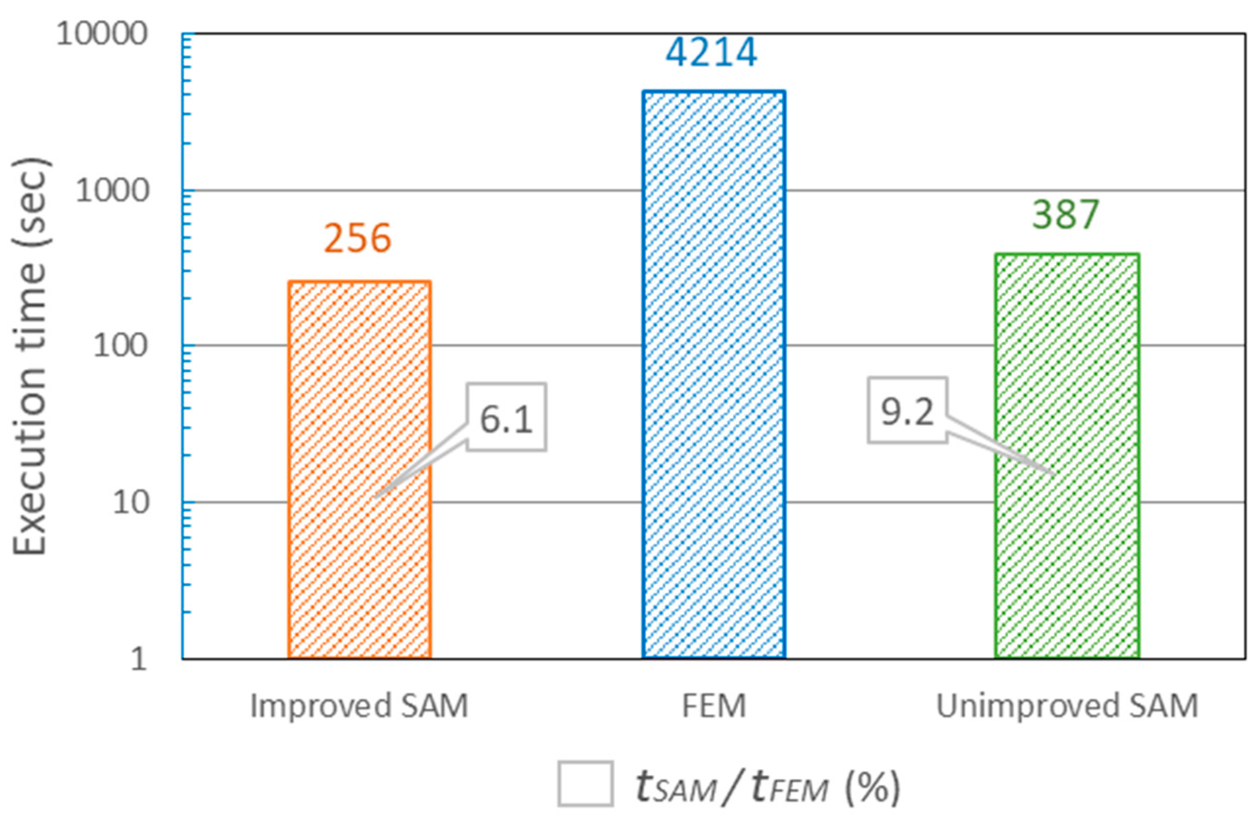
The efficiency of the unimproved SAM model with NEIM has been validated with the FEM model in our previous work [29]. Owing to the utilization of 3D discrete convolution and the fast Fourier transform (FFT) algorithm during the solving process, the computational efficiency of the new numerical method is further increased. To validate the efficiency of the current numerical method, the same simple case was solved as in Section 3.4 of [29], and the execution time of the new numerical method was compared with those of the 3D FEM contact model and the unimproved SAM model with NEIM. Figure 6 indicates the scheme of the simple case in our previous work [29], which is a sphere–plane contact model between a rigid spherical indenter and an inhomogeneous half-space with a cubic inhomogeneity. The total number of FEM computational grids is 253,517, which is approximately same with the grid number () in the SAM model, and all the cases are solved with an Intel® CoreTM i7-8700 CPU.

Figure 6.
Schematic of the simple case for the efficiency validation.
The execution times of the improved SAM, FEM, and unimproved SAM models are shown in Figure 7. When simulating the same contact issue between a rigid spherical indenter and a half-space inhomogeneous material, the execution time of the improved SAM model in this paper was just 6.1% of that of the FEM model, while the same value of the unimproved SAM model in our previous work was 9.2%. Accordingly, the high efficiency of the current numerical model when tackling the contact issue of an inhomogeneous material is validated.
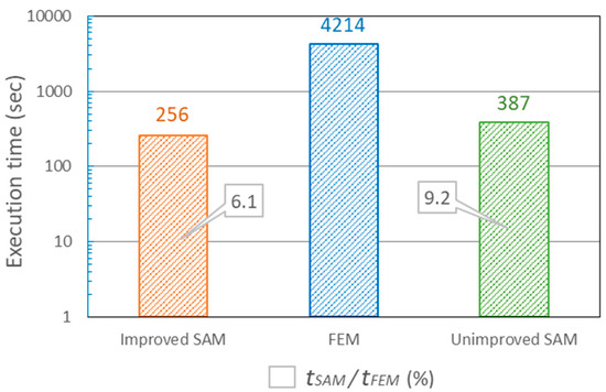
Figure 7.
Comparison of the execution time of the improved semi-analytical method (SAM), finite element method (FEM), and unimproved SAM models.
4. Model Validation
The accuracy and efficiency of the SAM model with NEIM have been validated with the FEM model for the particular contact case of inhomogeneous materials in our previous work [29]. While focusing on the Ti-(SiCf/Al3Ti)-laminated material with double-layered SiC fiber reinforcements, no macroscopic experiment was applied to validate the model. Compared with the FEM models, a macroscopic experiment is closer to the practical situation and can thereby provide more effective and practical validation. Accordingly, the proposed elasto-plastic contact model for the Ti-(SiCf/Al3Ti)-laminated composite with double-layered SiC fiber reinforcements was validated through the results comparison with the compressive load-strain curves of the indentation tests under the spherical indenter.
According to the microstructure characterization through SEM, the geometric model for the numerical simulation of the Ti-(SiCf/Al3Ti)-laminated composite with double-layered SiC fiber reinforcements is shown in Figure 8. As is proved in our previous work [25], fiber layers that are oriented perpendicular to the loading direction can bear much more load before material failure compared with those parallel to the loading direction. Therefore, only cases of loading perpendicular to the layers was considered in this work when investigating the reinforcing effect of the SiC fiber layers on the mechanical properties of the fiber-reinforced MIL composite. The geometric and material parameters are displayed in Table 1. The initial contact point between the rigid spherical indenter and the half-space was the origin, O, of the coordinate system. The loading direction was along the z axis pointing to the depth direction. All the material components in the model were set to be elasto-plastic.
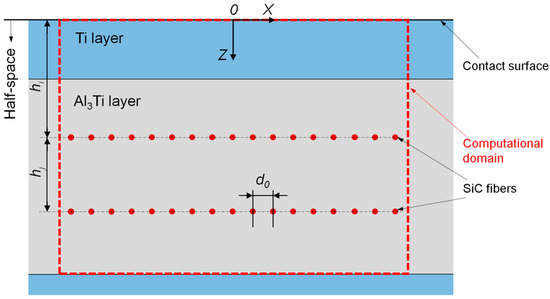
Figure 8.
XOZ cross section of the three-dimensional (3D) SAM model for validation.

Table 1.
Parameters of the new NEIM-based SAM model for validation.
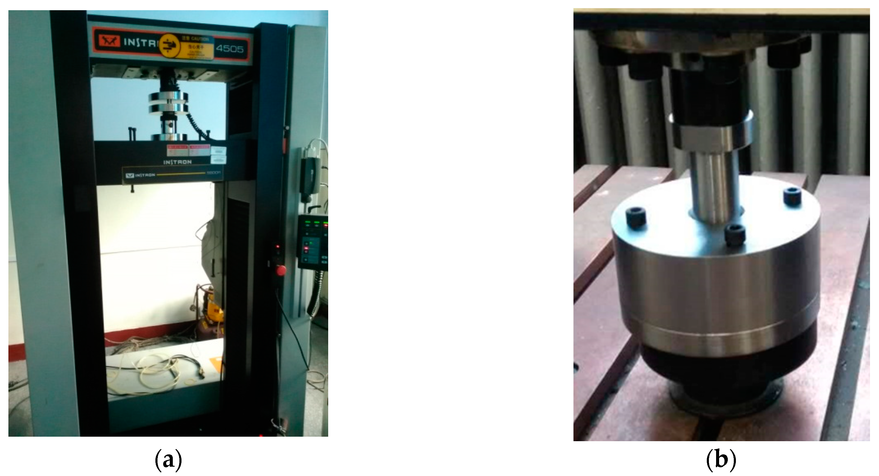
Correspondingly, the loading conditions of the compressive indentation tests are exactly the same as that of the numerical model. Independent tests were performed on the same three samples. The tests were conducted on an Instron 5500R load frame device, as shown in Figure 9a [29] at a strain rate of ~0.001/s at room temperature. The loads were applied in sphere–plane contact mode, as shown in Figure 9b, the spherical indenter can be considered to be a rigid body. The specimen configuration employed in the compressive indentation tests is indicated in Figure 10a [29]; the dimensions of the specimens were 12 mm × 12 mm × 12 mm, and the concentrated load applied by the spherical indenter initiated from the center point of the specimen surface. The measure method for the strain of the spherical indentation was same as that in the classical compressive test, except that the indenter possesses a spherical surface rather than a flat one. The result of indentation tests is displayed in the form of compressive load-strain curve. To be specific, the strain of the spherical indentation in this case is the ratio between the indenter displacement from the load start and the specimen height. Namely, the “strain” in the load-strain curve result is the strain along the z axis at the origin, O, of the coordinate system for the specimens, as shown in Figure 8 and the schematic diagram of Figure 3, which is also the initial contact surface between the spherical indenter and the specimen. It is worth mentioning that to scale up the compressive load-strain curves of indentation tests for a clearer comparison with the numerical model, the test specimens shown in Figure 10b comprised six “Ti-Al3Ti-SiC-Al3Ti” units layered along the loading direction.

Figure 9.
(a) Instron 5500R load frame device [29]; (b) Spherical indenter.
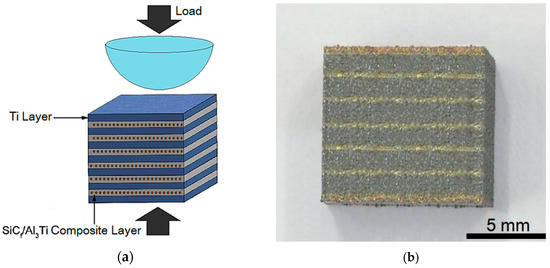
Figure 10.
(a) Specimen configurations employed in compressive indentation tests [29]; (b) Metallographic specimen configuration of Ti-(SiCf/Al3Ti) composite with double layered SiC fiber reinforcements.
5. Results and Discussion
5.1. Microstructure Observation and Characterization
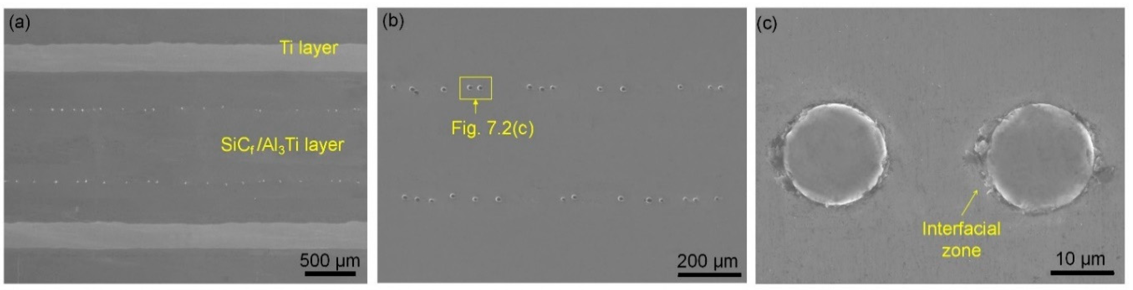
Figure 11 is the microscopic morphology of the as-fabricated Ti-(SiCf/Al3Ti)-laminated composite, indicating that the Ti foils have been completely consumed, and the composite was composed of alternating Ti metal layers and SiCf/Al3Ti fiber-reinforced intermetallic (FRI) layers. As shown in Figure 11a, there were two layers of SiC fiber rows equally distributed in each Al3Ti layer. The microstructure of the proposed intermetallic compound Al3Ti in this work was compact and uniform; no apparent “centerline” void or crack that may lead to a poor bond was observed. Moreover, as shown in Figure 11c, there was a layer of reaction product existing in the interfacial region between the fibers and the intermetallic compound; this layer did not completely surround the SiC fibers, and its thickness was not uniform. All in all, it was proven that the Ti barrier layers play an effective role in isolating the fibers from the oxides or voids at the “centerline”. Thus, the interfacial structure and properties between the SiC fibers and intermetallic compound Al3Ti were improved significantly, and the interfacial bonding strength was thereby enhanced. Accordingly, the reinforcement effect of the SiC fibers can be effectively guaranteed during the loading and failure process of the Ti-(SiCf/Al3Ti)-laminated composite, as the disturbance from the “centerline”, which has a weak interfacial bond and is easy to damage, is avoided.

Figure 11.
SEM micrographs of the Ti-(SiCf/Al3Ti)-laminated composite: (a) laminated structure, (b) SiCf/Al3Ti zone, and (c) interfacial zone.
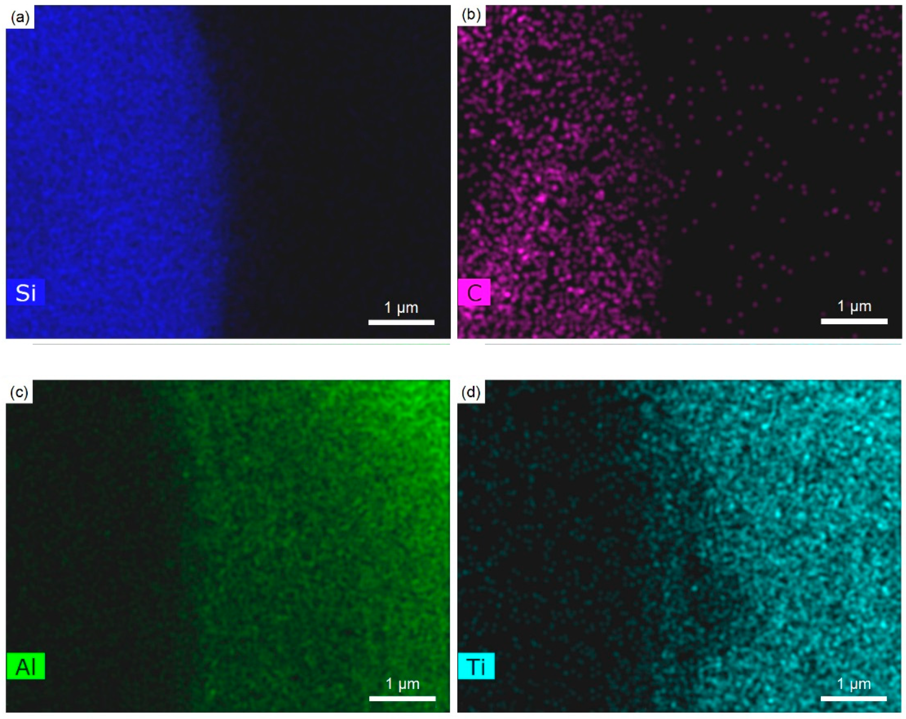
Moreover, EDS was carried out on the SiCf/Al3Ti layer of the Ti-(SiCf/Al3Ti)-laminated composite with double rows of SiC fiber reinforcements with the aim to investigate the distribution characteristics and diffusion rule of the elements in this layer. Figure 12a displays the distribution situation of different fiber rows in the intermetallic SiCf/Al3Ti layer. It can be observed that most of the fibers were distributed uniformly and arranged in line; to be specific, the adjacent fibers were in a complementary contact condition [42], and no fiber overlap occurred. Only a few fibers stacked together, but this kind of stacking phenomenon may have resulted in a hole-type defect among the stacked fibers. This particular defect is harmful to the bonding between the fibers and the intermetallic compound and thereby does damage to the reinforcement performance of the fibers on the laminated composite. Hence, this microstructure defect should be removed by properly controlling the interval distance and uniformity degree of the fibers. According to the element distribution maps of Figure 12, no area of poor Al or Ti was found other than the regions where fibers were located, and the elements were distributed uniformly, suggesting that there was no defect, such as a void or crack, in the as-fabricated Ti-(SiCf/Al3Ti)-laminated composite with intermetallic layers reinforced by double rows of fibers. In addition, the microstructure was compact, and the components were distributed uniformly.
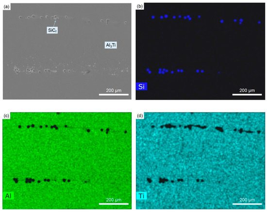
Figure 12.
(a) The SEM image and (b–d) the element distribution maps of Si, Al, and Ti in the Ti-(SiCf/Al3Ti)-laminated composite.
Furthermore, there was a certain quantity of residual Al phase around some of the SiC fibers. It can be observed from the element distribution results in Figure 12b–d and Figure 13 that the areas around the SiC fibers were rich in Al and poor in Ti and also contained some element C, but basically no Si was discovered to exist in these areas. Accordingly, it can be inferred that the areas around the SiC fibers were Al phase accumulation areas. Moreover, there may also exist a small amount of Al–C compound, as well as atom Ti, which is dissolved in the crystal lattice of the Al, forming a solid solution. Referring to the previous works [43], the small amount of residual phase Al in Ti-(SiCf/Al3Ti)-laminated composite can play a positive role in increasing the toughness of the overall composite material.

Figure 13.
The element distribution maps of (a) Si, (b) C, (c) Al, and (d) Ti in the SiCf/Al3Ti interfacial zone.
In conclusion, this kind of Ti-(SiCf/Al3Ti)-laminated composite with intermetallic Al3Ti layers reinforced by double rows of SiC fibers has a well-organized microstructure and a higher volume fraction of fibers. Additionally, the SiC fibers are tightly bonded with the intermetallic compound Al3Ti, and the interfaces between them are continuous and complete. Thus, during the loading process of the Ti-(SiCf/Al3Ti)-laminated composite, the load can be transferred from the intermetallic compound to fiber reinforcements successfully and smoothly. Coupled with the increase of the fiber volume fraction, the comprehensive mechanical performance of the laminated composite has been improved considerably.
5.2. Model Validation Results
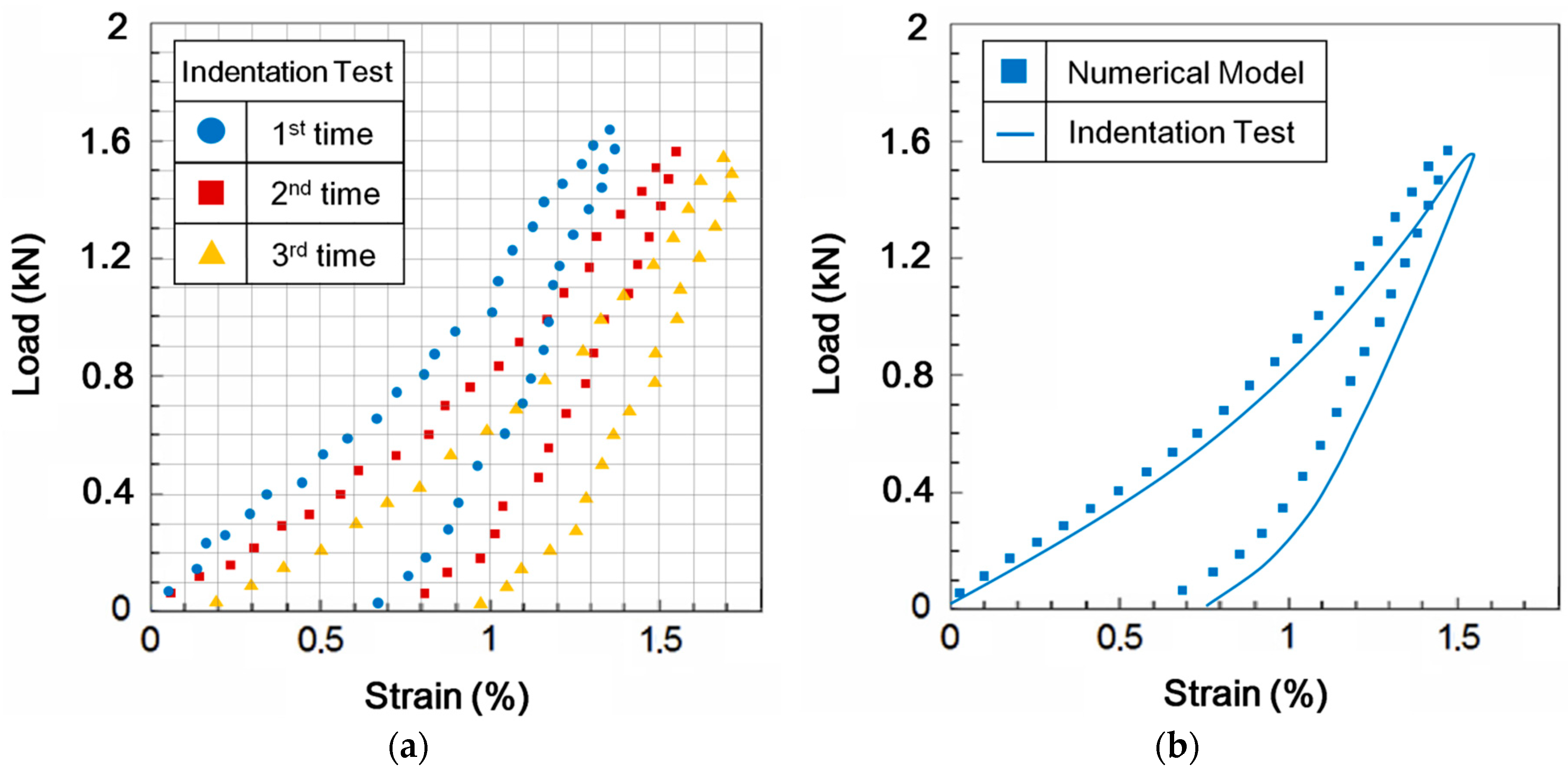
The original data of the compressive load-strain curves obtained by the indentation tests with the spherical indenter on the specimens of the as-fabricated double-row SiC fiber-reinforced Ti-(SiCf/Al3Ti) composite is displayed in Figure 14a. Note that there are some discrete points that are irrational as a result of random error during the tests. Therefore, the final result of the indentation tests for the model validation was achieved by removing such irrational values and then averaging the three groups of original data allowing for the existence of statistical error. The modified curve is shown in Figure 14b.
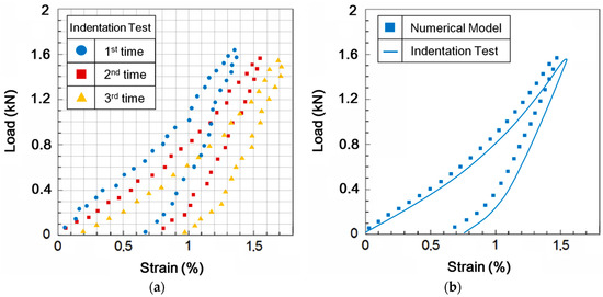
Figure 14.
(a) Original data of the compressive load-strain curves obtained with the indentation tests; (b) Results comparison of the compressive load-strain curves obtained from the 3D SAM model and indentation tests.
As plotted in Figure 14b, the load-strain curves solved with the numerical model and the compressive indentation test were compared. The overall variation tendency of the two curves was about the same. However, there still existed some system deviations in that the strains in the numerical model were all slightly lower than the corresponding values in the indentation test, especially when the load was completely removed. This deviation can be attributed to the different configurations in the loading region of the two methods. For the numerical model, the load was applied on an ideal, infinite half-space, which is closer to the practical loading region of the Ti-(SiCf/Al3Ti)-laminated composite as a sheet material. However, the specimens loaded in compressive indentation test were small cubes that contained four free surfaces. This made the deformation within the material due to the normal load easier to extend out horizontally through the free surfaces. Accordingly, the specimens were “softer” than the ideal half-space material, which means that they will deform more in a vertical direction than will the half-space material under the same load.
Moreover, according to Figure 14b, it should be noted that the elastic recovery of the tested specimens was 0.74%, because the applied load was decreased until it was completely removed, while the same value for the ideal half-space material in the numerical model was 0.81%. This suggests that the elastic recovery ability of ideal half-space material in the numerical model was better than that of the specimens under the compressive indentation tests. This phenomenon can also be observed from another perspective: the strain deviation between the two curves was 0.08% after the loading process finished, while the strain deviation between the two curves rose to 0.12% after the unloading process finished and the elastic deformation of specimens was fully recovered. This indicated that there was a higher deviation in the residual strain of the indentation after the load was completely removed. This result can be attributed not only to the fact that the specimens were “softer” than the ideal half-space material, as discussed above, but also to the existence of friction in the loading device during the indentation tests. Therefore, the elastic deformation of the specimens could not fully recover as the ideal half-space material does in a numerical simulation after the load was completely removed.
Nevertheless, the maximum deviation was less than 15%, and a good agreement was achieved. Therefore, the SAM model with NEIM as described in Section 3 was validated to be a feasible way to simulate the elasto-plastic sphere–plane contact of the Ti-(SiCf/Al3Ti)-laminated composite with double-layered SiC fiber reinforcements.
5.3. Contact Analysis for the Ti-(SiCf/Al3Ti) Composite under Varying Loads
For the numerical contact model in the model validation, the elasto-plastic contact behaviors of the Ti-(SiCf/Al3Ti)-laminated composite with double rows of SiC fiber reinforcements under increasing loads are shown in Figure 15. The results are demonstrated by way of the Von Mises stress field.
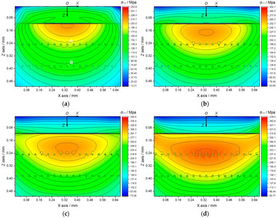
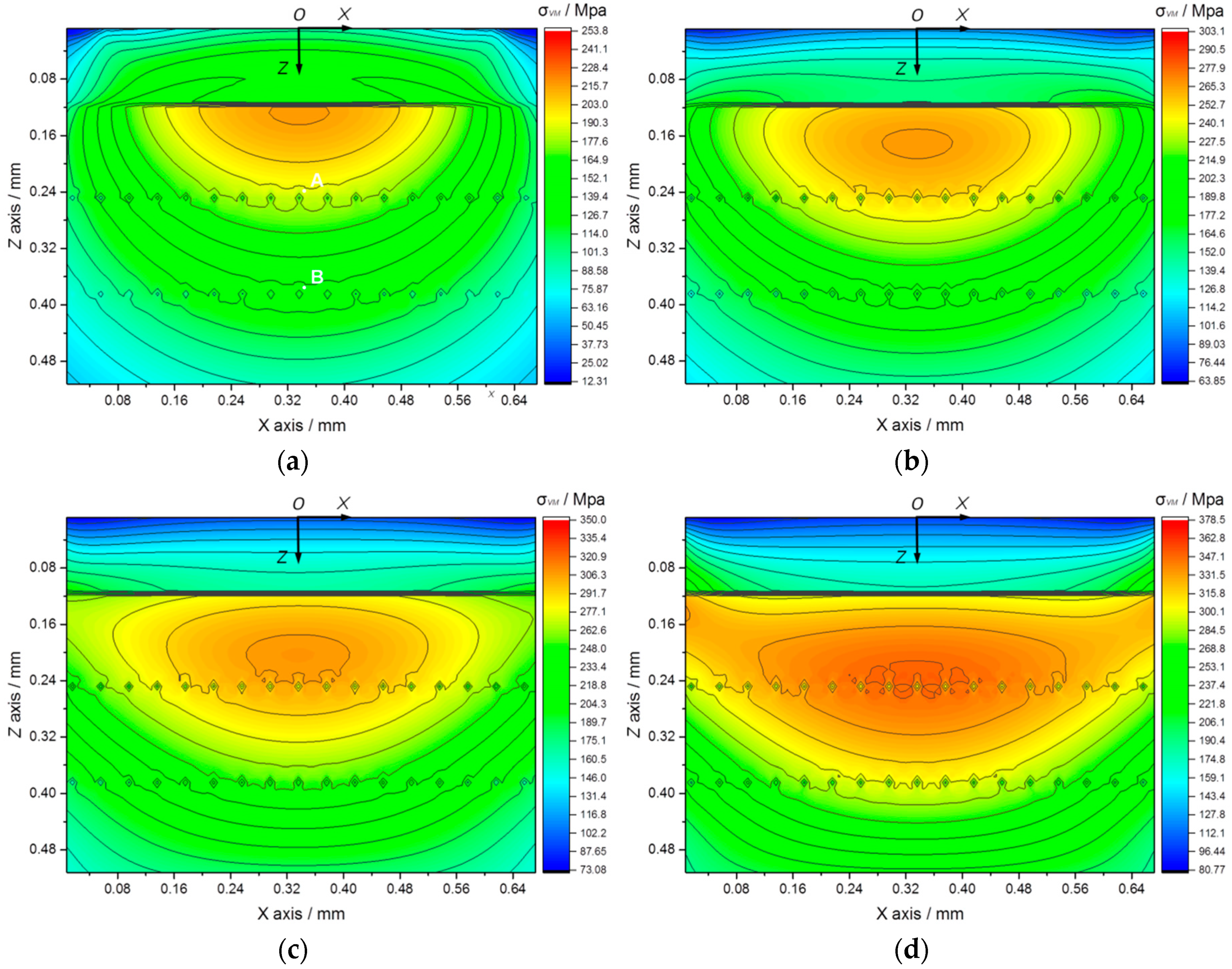
Figure 15.
Von Mises stress field evolution in cross-section XOZ of the Ti-(SiCf/Al3Ti)-laminated composite with increasing loads: (a) 0.4 kN, (b) 0.8 kN, (c) 1.2 kN, and (d) 1.6 kN.
According to Figure 15a–d, as the load rises, the plastic strain concentration region, which has a typical plastic strain distribution pattern during sphere–plane contact loading and can result in stress concentration in the corresponding region, goes down along the depth direction and expands in size. It is apparent that SiC fiber reinforcements can effectively slow down the stress contours from propagating to deeper layers, which is reflected by the “pull” effect on the stress contours around the SiC fibers. In particular, when the maximum plastic strain concentration region descends to overlay the reinforcing SiC fiber row, as displayed in Figure 15d, the original elliptical maximum stress concentration region can be split into several parts by the reinforcing effect of the SiC fibers, and the size, as well as the maximum stress value of this region, are thereby decreased. This suggests that the SiC fiber rows play an effective role in bearing the load and dispersing the stress more evenly, especially when the load rises to a high level. Consequently, the strength and toughness of Ti-(SiCf/Al3Ti)-laminated composite are enhanced.
It should be noted that no stress concentration occurs in the Ti layer or the SiC fibers compared with the Al3Ti layer. This phenomenon can explain the failure behavior of the Ti-(SiCf/Al3Ti)-laminated composite during the three-point bend (TPB) tests in a previous work [25], during which cracks initiate in the Al3Ti layer rather than in the Ti layer or the SiC fibers. This can be attributed to the high ductility and toughness of the Ti layer, as well as the high strength of the SiC fibers. Therefore, the failure behavior first occurs in the brittle, intermetallic Al3Ti layer. Accordingly, to study the stress concentration issue in the Al3Ti layer is significant to predict the failure location of the Ti-(SiCf/Al3Ti)-laminated composite during the loading process.
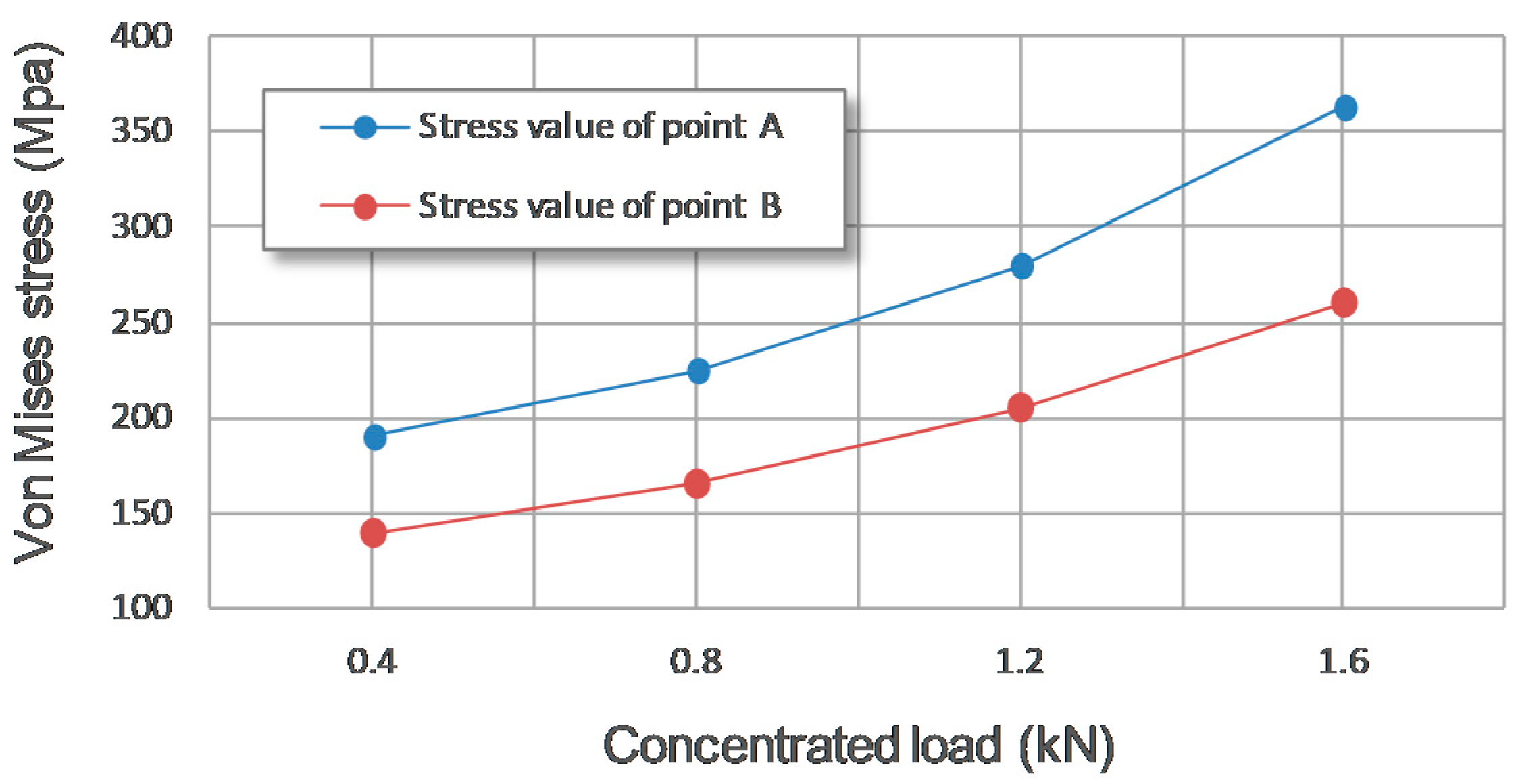
However, as shown in Figure 15c,d, when the plastic strain concentration region approaches the SiC fiber row, the existence of the SiC fiber reinforcements may also induce some tiny irregularly shaped stress concentration regions around the fibers. This phenomenon can also be observed from another perspective, as shown in Figure 15a; point A and B are the maximum stress values around the center SiC fiber in the first and second rows, respectively. It can be seen in Figure 16 that as the concentrated load increases and the plastic strain concentration region goes down, the stress value of point A, which is closer to the plastic strain concentration region, rises more dramatically than the stress value of point B, which is relatively further from that region. This indicates that when the plastic strain concentration region approaches the SiC fibers, it will indeed induce some stress concentration around the fibers. Given that defects such as voids and the “centerline” are most likely to occur in the interfacial regions around the SiC fibers, those irregularly shaped stress concentration regions mentioned above may first lead to material failure when the load is high enough. Therefore, the appearance of irregularly shaped stress concentrations around the SiC fibers should be avoided by adjusting the geometric parameters of the microstructure and improving the sintering technique.
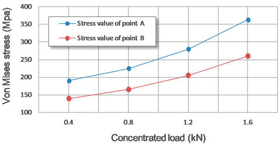
Figure 16.
Stress magnitude at point A (the maximum stress value around the center SiC fiber in the first row) and point B (the maximum stress value around the center SiC fiber in the second row) for the four stress fields with increasing loads.
5.4. Parametric Studies
5.4.1. Effect of Size of SiC Fibers
The diameter of SiC fibers can directly affect the reinforcing effect on the Ti-(SiCf/Al3Ti)-laminated composite. To determine the appropriate diameter of the SiC fibers for better mechanical performance, four comparative tests with different fiber diameters were conducted with the proposed SAM model. The vertical interval between the double SiC fiber rows and contact load were both fixed at 136 μm and 1.2 kN, respectively. According to our previous work [29], the horizontal center distance between the adjacent SiC fibers disturbs the stress distribution significantly; therefore, it was fixed at 2.5 times of fiber diameter in this case. The other parameters were identical to the ones in the validation model. The results are shown below.
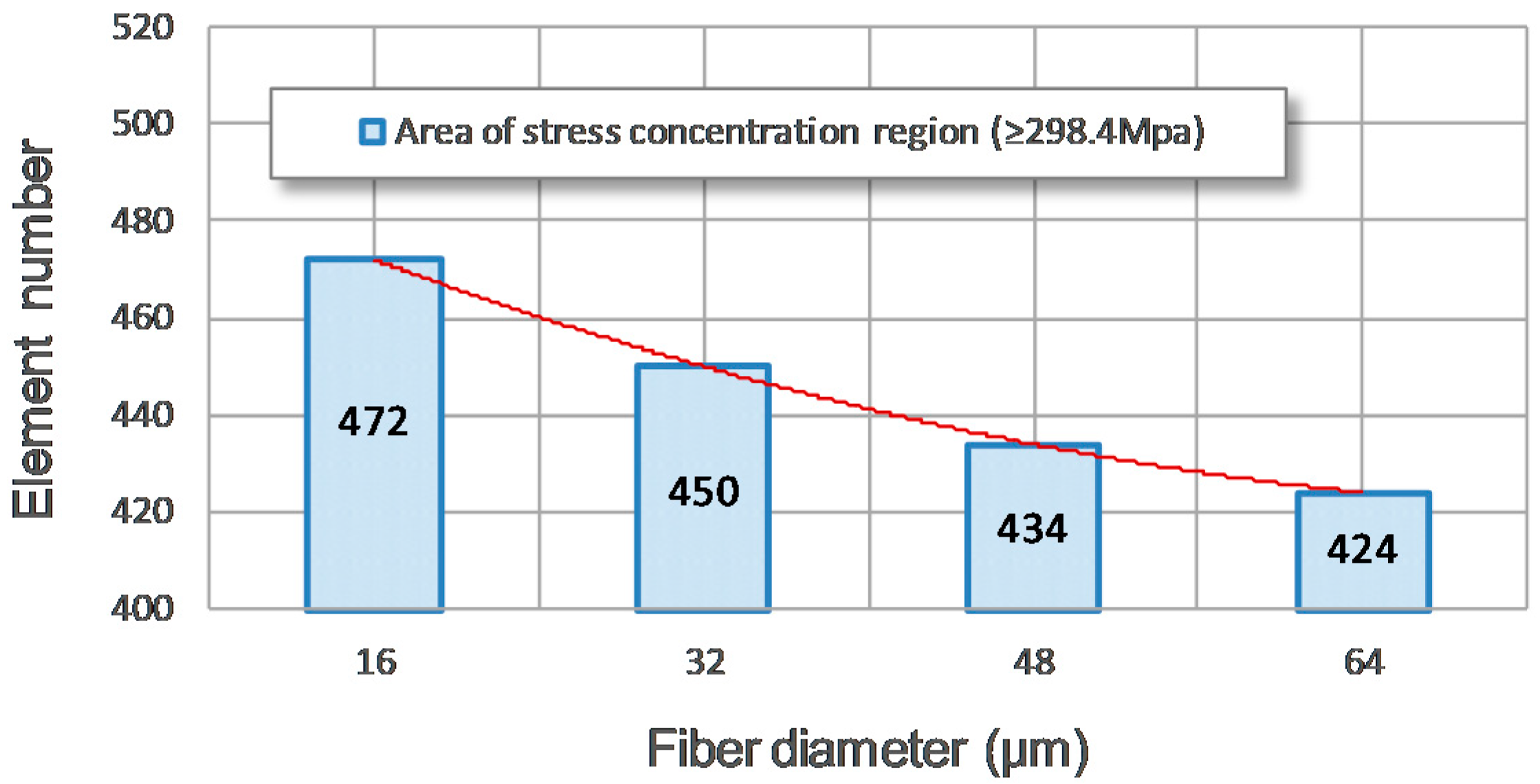
As is well-known, when the cracks in the Al3Ti layer extend to the interface between the SiC fiber and the matrix material, the cracks will deflect to bypass the fiber and keep propagating along the interface. The crack propagation path is thereby extended, and more fracture energy is consumed. This is the main toughening mechanism of SiC fiber reinforcement [44]. Apparently, the bigger the fibers, the longer crack propagation path, and thus, the more fracture energy will be consumed. According to Figure 17, bigger fibers indeed bear a greater contact load and decrease the size, as well as the maximum stress value of stress concentration region, significantly. This phenomenon can also be observed from another perspective. As shown in Figure 17a, the stress concentration region in this case is defined as the contoured region in which the stress magnitude is over 298.4 MPa. The area of the stress concentration region is measured by the element number of the numerical model. As shown in Figure 18, as the diameter of the reinforcing SiC fiber increases, the area of the stress concentration region indeed decreases steadily. Furthermore, after the load is completely removed, the bigger fibers can also provide more restoring force owing to their higher toughness. Accordingly, increasing the diameter of the reinforcing SiC fibers can enhance the strength and toughness of the SiCf/Al3Ti layer in some respects.
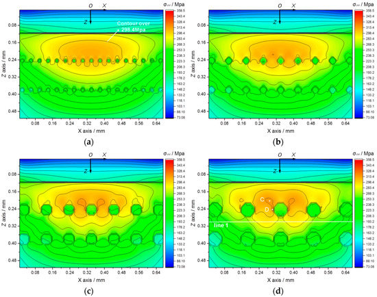
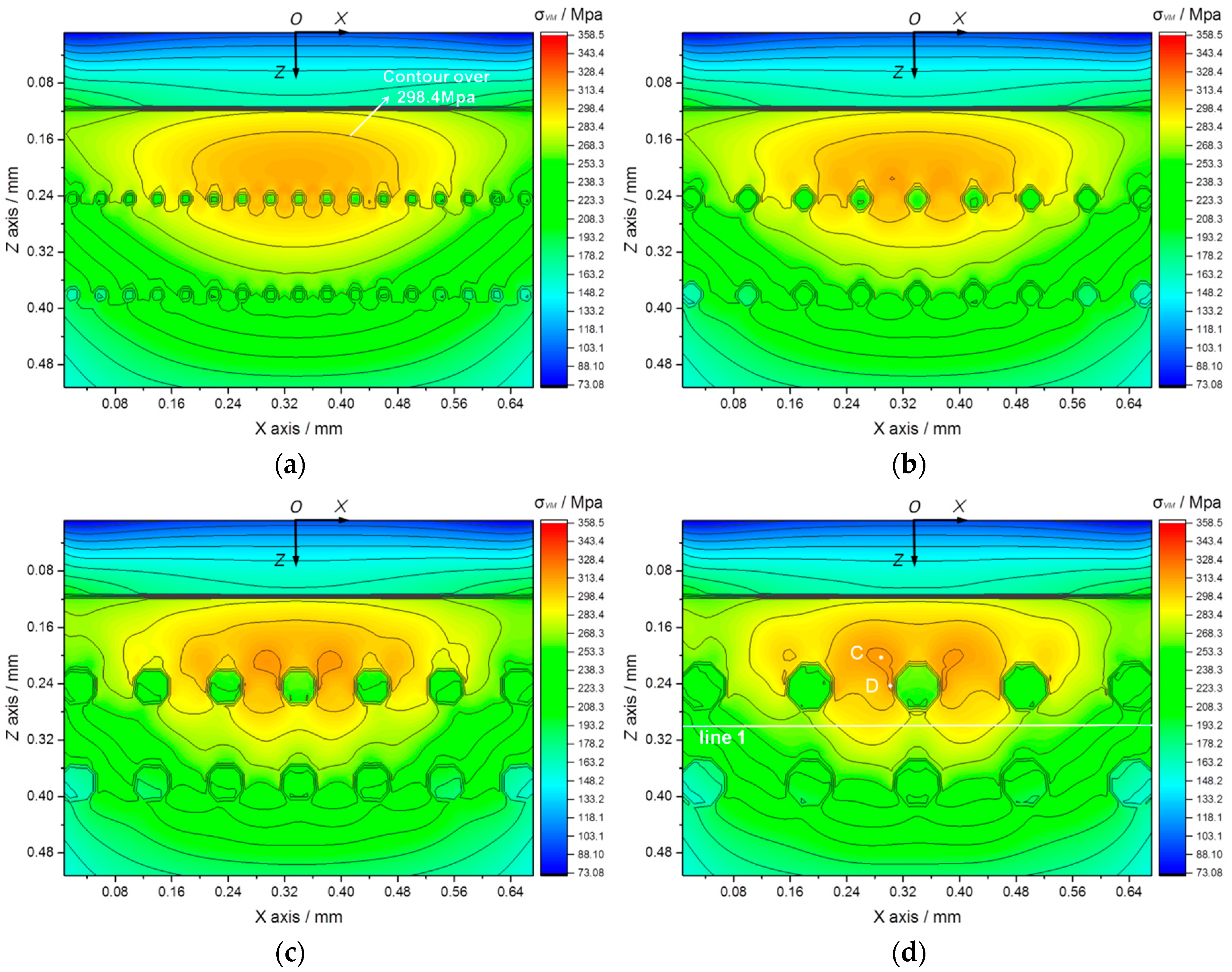
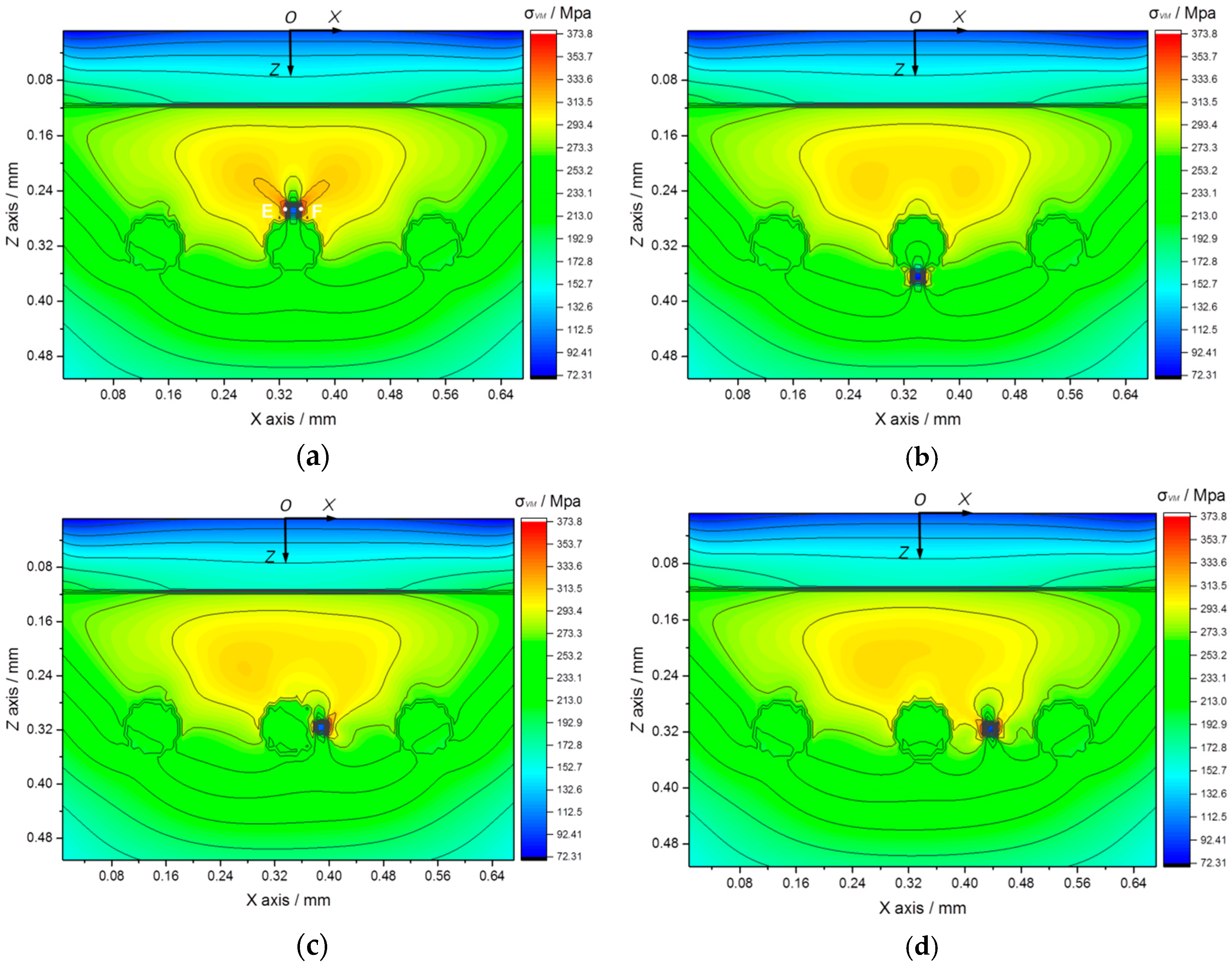
Figure 17.
Von Mises stress fields in cross section XOZ with increasing fiber diameters: (a) 16 μm, (b) 32 μm, (c) 48 μm, and (d) 64 μm.
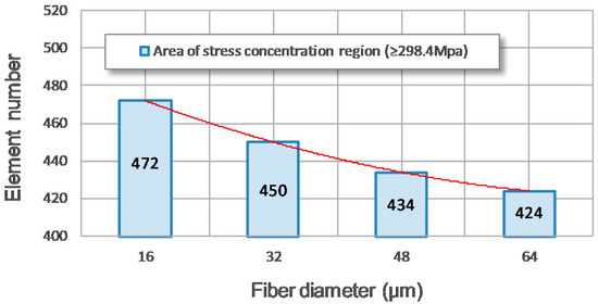
Figure 18.
Area of stress concentration region (≥298.4 MPa) for the four stress fields with increasing SiC fiber diameters.
However, it can be observed from Figure 17c,d that when the diameter of the fibers rises above 32 μm, the stress concentration on both sides of the center fiber in the first row grows remarkably. This can also be observed in the stress value curve in Figure 19, in which points C and D are the maximum stress value of stress concentration region and the position on the side of the center SiC fiber in the first row, respectively, as shown in Figure 17d. The stress value of point C first decreases slowly as the fiber diameter increases, and then, there is a sudden rise when the fiber diameter reaches over 32 μm. As for the tress value of point D, it rises continuously with the increasing of the fiber diameter. However, when the fiber diameter increases from 32 μm to 48 μm, the stress value of point D rises much more dramatically than the average trend, because the stress value of point D is higher than that of point C. This suggests that when the diameter of the fibers rises above 32 μm, the position where the maximum stress value occurs changes from the stress concentration region to the side of the center SiC fiber of the first row, and meanwhile, the value rises dramatically. This can be attributed to the induction effect of the large diameter fibers on the stress field concentration around the fibers, so that the maximum stress concentration region is transferred from the original position, which is above the fiber, to the positions on both sides of the center fiber. Those newly formed positions are in the interfacial zone between the SiC fiber and the intermetallic compound Al3Ti. Given that the interfacial zone may contain hole defects that can reduce the bonding strength of this region, the high stress concentration in this region is very likely to generate cracks, further leading to material failure. So, when the fibers are too big, the risk of material failure is increased due to the increase of the stress concentration in the interfacial zone.
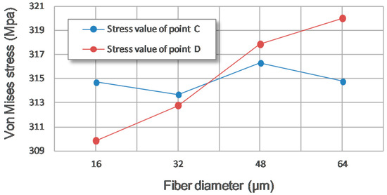
Figure 19.
Stress magnitude at point C (the maximum stress value of the stress concentration region) and point D (the maximum stress value on the side of the center SiC fiber) for the four stress fields with an increasing SiC fiber diameter.
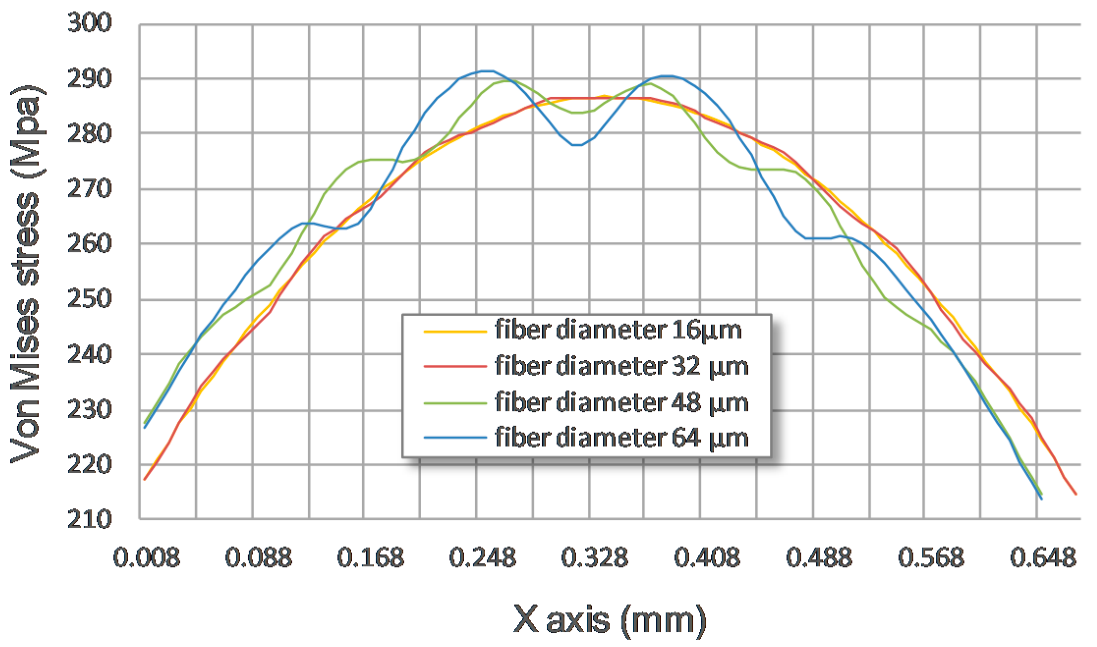
In addition, limited by the sintering fabrication process with the foil–fiber–foil method, bigger fibers mean that a wider center distance between the adjacent fibers is required, otherwise the defect of the “centerline” would occur, which is attributed to the poor thermo-fusing bonding between the foils above and below the SiC fibers during the sintering process. While, comparing the stress fields in Figure 17b–d, the stress distribution at line 1 for the four fields with an increasing SiC fiber diameter (shown in Figure 3) is obtained. As shown in Figure 17d, line 1 is in cross section XOZ and at the depth of 0.3 mm from the contact surface. Before the concentrated load propagates to the position of line 1, it goes through the “pull” effect of the first row of reinforcing SiC fibers. So, the stress value and distribution at this line is under the disturbance of all the reinforcing SiC fibers in the first row. As shown in Figure 20, as the fiber diameter increases, the stress distribution curve at line 1 fluctuates more, and the maximum stress magnitude at line 1 increases as well. This suggests that the wider center distance between the adjacent fibers allows the stress concentration region to propagate to the deeper layer, passing through the fiber row. Moreover, the wider center distance between the adjacent fibers makes the stress contour propagate to the deeper layer much more unevenly, which means the deeper layer engages in relatively less uniform loading and, therefore, more stress concentration regions will be generated. This indicates that bigger fibers with sparsely arranged rows cannot reinforce the intermetallic Al3Ti layer as effectively as smaller fibers with closely arranged rows when the fiber diameter is over 32 μm. Furthermore, the cost of bigger SiC fibers and the cost of the sintering fabrication of a Ti-(SiCf/Al3Ti)-laminated composite employing bigger SiC fibers are all relatively higher.

Figure 20.
Stress distribution at line 1 for the four stress fields with an increasing SiC fiber diameter.
All in all, the optimal diameter of the SiC fiber reinforcements is 32 μm when the horizontal center distance between the adjacent fibers is fixed at 2.5 times the fiber diameter, at which value the SiC fiber row can bear the load and hold it back from propagating to the deeper layer to the maximum extent and also retain its uniform loading form during the propagation.
5.4.2. Effect of Position of Hole Defect
As shown in Figure 21, there are often voids that come into being in the interfacial zone between the SiC fiber and Al3Ti intermetallic compound matrix in the Ti-(SiCf/Al3Ti)-laminated composite because of the existence of oxides and other impurities in the foils during the sintering process. These kinds of voids can be treated as hole defects and usually appear around the SiC fiber reinforcements. According to our previous works [6,25,30], the positions where a hole defect is likely to occur can be generalized into four typical cases relative to the reinforcing SiC fibers, which are indicated in Figure 3b. In order to investigate the harmful effect of a hole defect on the strength and stability of the microstructure in the SiCf/Al3Ti layer, as well as the relationship between the hole defect’s position and hazard degree, four numerical comparative tests with different positions of hole defects were carried out. The contact load was fixed at 1.2 kN. The results are shown in Figure 22.
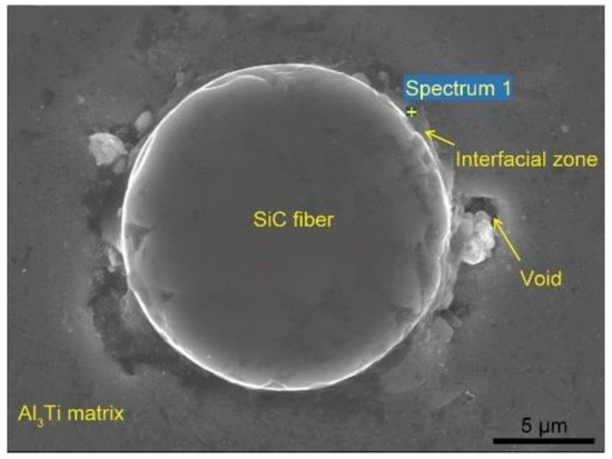
Figure 21.
SEM micrograph of the interfacial zone between the SiC fiber and the Al3Ti intermetallic compound matrix in the Ti-(SiCf/Al3Ti)-laminated composite.
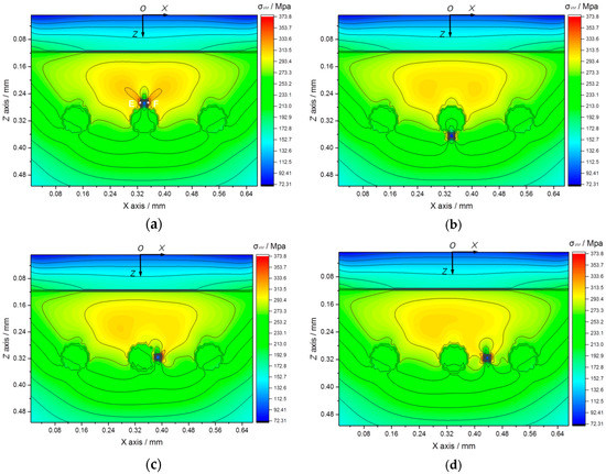
Figure 22.
Von Mises stress fields in cross section XOZ with different positions of hole-defect relative to reinforcing SiC fibers: (a) above, (b) below, (c) on the side and (d) in the middle between adjacent fibers.
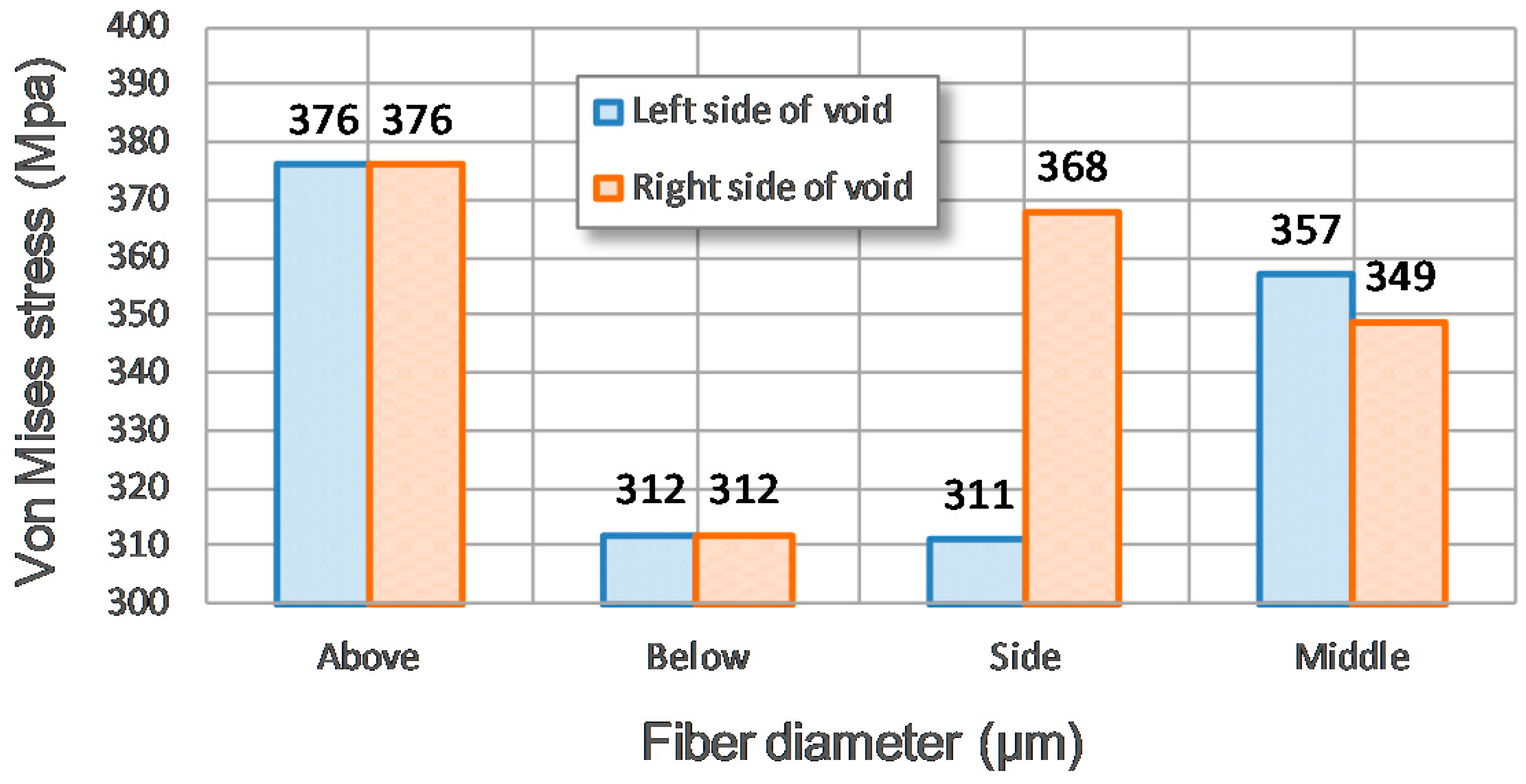
According to the stress distributions of the four fields with different positions of hole defects in Figure 22, it is obvious that the maximum stress concentration is located in both sides of the void under a normal load. Comparing the four stress fields with different positions of hole defects relative to the reinforcing SiC fibers, Figure 23, showing the stress magnitude on both sides of the void, can be obtained. It should be noted that the maximum value of the stress concentration around the void above the fiber is much higher than that of the void below the fiber. The stress field in the plastic strain concentration region is obviously disturbed by the void above the fiber, which is clearly higher than that of the void below the fiber. This is because the void above the fiber cannot be protected by a reinforcing fiber that can withstand a considerable portion of the load, so the void defect above the fiber is subject to a relatively higher load passed by the Al3Ti intermetallic compound matrix, and the matrix material on both sides of the void thereby deforms severely. Therefore, the void above the fiber can weaken the strength of the SiCf/Al3Ti layer more pronouncedly than can the void below the fiber.
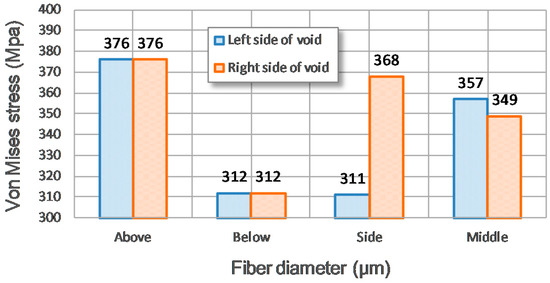
Figure 23.
Stress magnitude on the both sides of the void for the four stress fields with different positions of hole defects relative to the reinforcing SiC fibers.
As for the voids on the side of the fiber and in the middle between the adjacent fibers, the maximum values of the stress concentration around the voids are almost same, and both are between the values of voids above and below the fiber. Comparing the stress values around the voids on the right side of fiber and in the middle between the adjacent fibers shown in Figure 22, although the maximum values of the stress concentration around the voids are about the same, the void on the side of fiber is subject to a one-sided stress concentration rather than the two-sided ones in the other three cases. This can be attributed to the support of the tough SiC fiber with small deformation, which can provide three small regions in the Al3Ti matrix on both sides and the bottom of the fiber possessing very little deformation. The side of the void that is adjacent to the fiber is just within those regions; hence, there is very little stress concentration in this side, as shown in Figure 22c and Figure 23. Thus, the stress concentration region in the stress field when the void is on the side of the fiber is reduced compared with that when the void is in the middle between the adjacent fibers. Therefore, the void on the side of the fiber can do less harm to the strength of the SiCf/Al3Ti layer than can the void in the middle between the adjacent fibers.
In conclusion, the void positions relative to the reinforcing SiC fiber are listed in descending order according to their hazard degree with respect to the strength of the SiCf/Al3Ti layer as follows: above, in the middle between the adjacent fibers, on the side, and below.
5.4.3. Effect of Number of SiC Fiber Rows
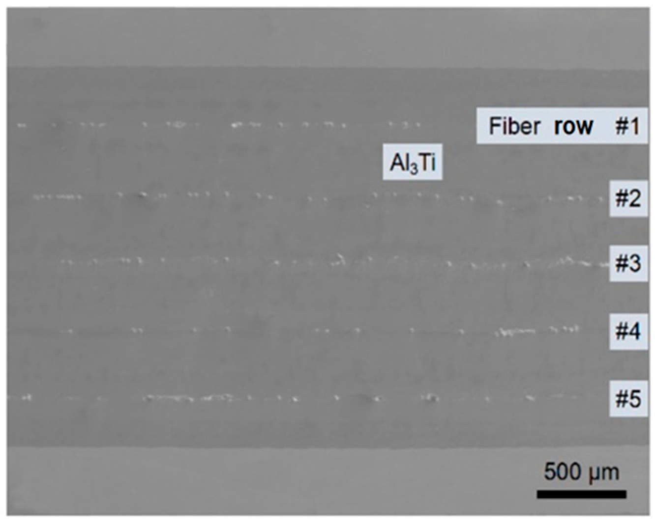
According to the current sintering technique with the FFF method, the Ti-(SiCf/Al3Ti)-laminated composite with five rows of SiC fiber reinforcements is fabricated as shown in Figure 24. The volume fraction of the SiC fiber reinforcements is increased dramatically to enhance the strength and toughness of the laminated composite. Aiming to study the relationship between the quantity of SiC fiber rows and the reinforcing performance on the SiCf/Al3Ti layer, four numerical comparative tests with an increasing number of SiC fiber rows were performed. The fiber diameter was fixed at 8 μm, and the vertical intervals between the adjacent fiber rows were the same, which was in accordance with the practical situation. The thickness of the SiCf/Al3Ti layer was fixed at 400 μm in the numerical model, and the contact load was 1.2 kN. The results are displayed in Figure 25 as follows.
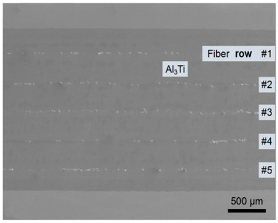
Figure 24.
SEM micrographs of the Ti-(SiCf/Al3Ti)-laminated composite with five rows of SiC fiber reinforcements.
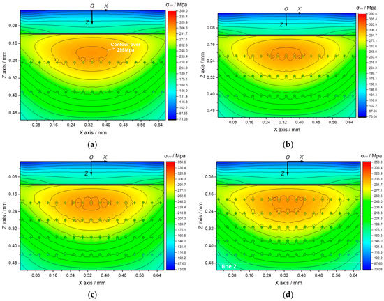
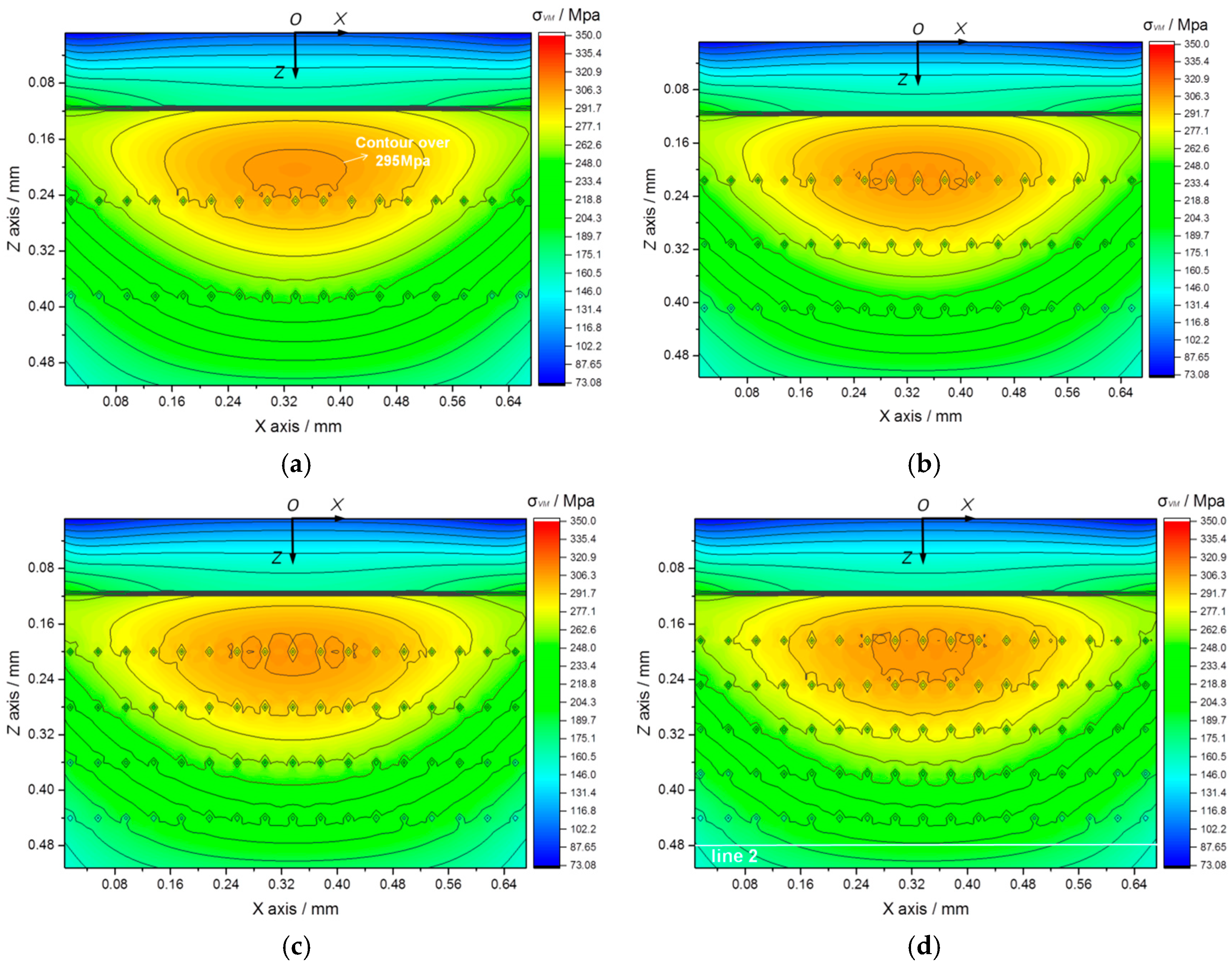
Figure 25.
Von Mises stress fields in cross section XOZ with increasing numbers of reinforcing SiC fiber rows: (a) 2 rows, (b) 3 rows, (c) 4 rows, and (d) 5 rows.
As shown in Figure 25a–d, more fiber rows can indeed make the stress contours flatter and more uniform when propagating to the deeper layer. This phenomenon can also be observed from another perspective. As shown in Figure 25d, line 2 is in cross section XOZ and at the depth of 0.48 mm from the contact surface. Before the concentrated load propagates to the position of line 2, it goes through the “pull” effect of all the reinforcing SiC fiber rows. So, the stress value and distribution at this line is under the disturbance of all the reinforcing SiC fiber rows. As shown in Figure 26, with the quantity of reinforcing SiC fiber rows increasing, the stress distribution curve at line 2 becomes flatter, and the maximum stress magnitude at line 2 drops as well. This indicates that as the quantity of the reinforcing fiber rows increases, the contact load propagating within the SiCf/Al3Ti layer tends to be more uniform; that is, the stress concentration occurring right under the contact point and along the loading direction, which is attributed to sphere–plane contact loading, can be released to some extent. Meanwhile, to reflect the overall mechanics status and bearing condition of the SiCf/Al3Ti layer, a new concept, which states the average stress value of all the elements in the SiCf/Al3Ti layer, is introduced. As shown in Figure 27, the average stress value of the SiCf/Al3Ti layer decreases apparently as the quantity of reinforcing fiber rows goes up from 2 to 5. This suggests that more rows of SiC fiber reinforcements indeed can enhance the strength of the SiCf/Al3Ti layer.
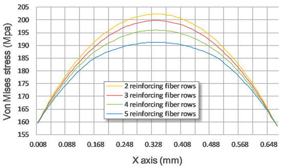
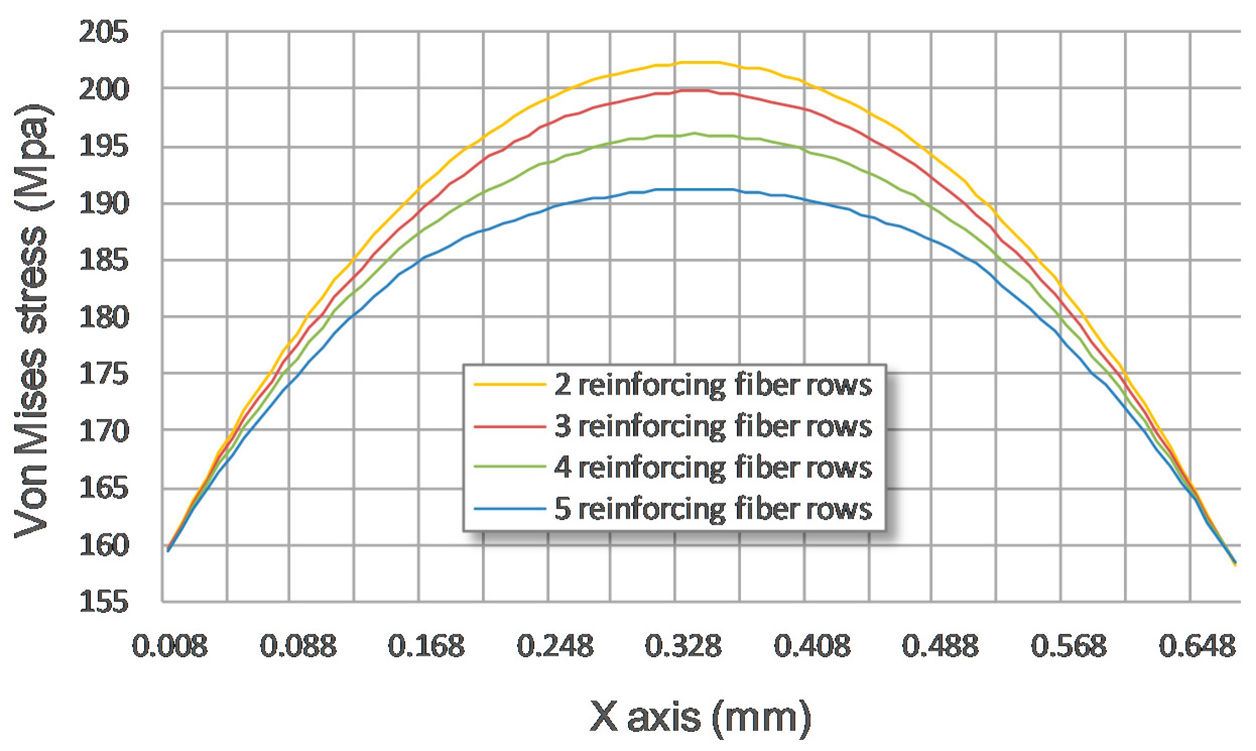
Figure 26.
Stress distribution at line 2 for the four stress fields with different quantities of reinforcing fiber rows.
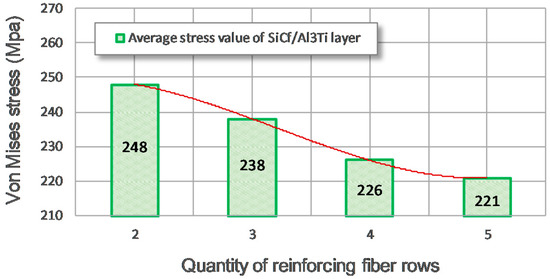
Figure 27.
The average stress value of the SiCf/Al3Ti layer for the four stress fields with different quantities of reinforcing fiber rows.
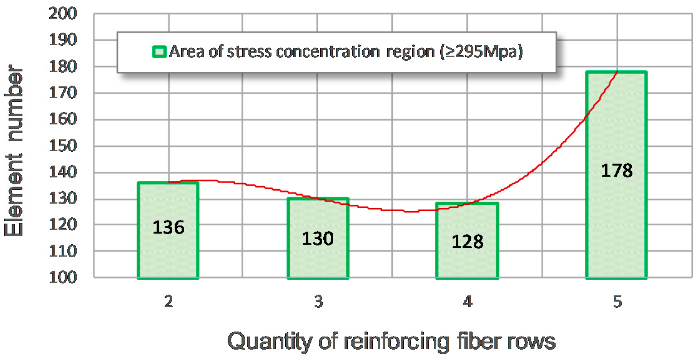
Nevertheless, the more densely arranged SiC fiber rows would give rise to the expansion of the stress concentration region, as shown in Figure 25d. According to the discussion in Section 5.3, it is known that the existence of SiC fiber reinforcements induces some tiny irregularly shaped stress concentration regions around the fibers during the loading process. Those regions connect together when the fiber rows become too close, and the original stress concentration region is thereby expanded dramatically, as shown in Figure 25d. This phenomenon can also be observed from another perspective. As shown in Figure 25a, the stress concentration region in this case is defined as the contoured region in which the stress magnitude is over 295 MPa. The area of the stress concentration region is measured by the element number of the numerical model. As shown in Figure 28, as the quantity of the reinforcing SiC fiber rows increases, the element number of the stress concentration region first drops slowly and then rises dramatically when the quantity of reinforcing SiC fiber rows goes up to 5. This indicates that the area of stress concentration region indeed increases dramatically when the quantity of the reinforcing fiber rows goes up from 4 to 5 and the fiber rows are close enough. Thus, the possibility of crack initiation or growth in the SiCf/Al3Ti layer is raised considerably. Furthermore, considering the current sintering fabrication technique and the purity of the raw foils before sintering, the more SiC fiber rows, the more difficult the sintering fabrication. Thus, the cost of sintering fabrication is increased. Moreover, because the impurities such as oxides exist on the surface of the raw foils before sintering, more SiC fiber reinforcement layers mean that more foils are employed in the sintering process and more impurities are introduced into the fabricated Ti-(SiCf/Al3Ti)-laminated composite. Those extra impurities will aggravate the “centerline” effect, as well as other kind of defects.
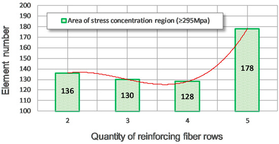
Figure 28.
Area of the stress concentration region (≥295 MPa) for the four stress fields with different quantities of reinforcing fiber rows.
Therefore, when the thickness of the SiCf/Al3Ti layer is 400 μm and the fiber diameter is 8 μm, the optimal quantity of the reinforcing SiC fiber rows is four, at which value the contact load propagating within the SiCf/Al3Ti layer can be made uniform to the maximum extent before the expansion of the stress concentration region takes place.
6. Conclusions
In this work, an innovative laminated composite material Ti-(SiCf/Al3Ti) with double-layered SiC fiber reinforcements was devised and fabricated. The characterization of the composite’s microstructure and interface was performed via SEM and EDS. A SAM model with NEIM was employed to simulate the elasto-plastic sphere–plane contact and was validated by compressive indentation tests. 2D and 3D FFT were applied during the solving process to boost the computational efficiency. The effects of the parameters including the SiC fiber diameter, hole defect position, and number of SiC fiber rows on the stress fields were investigated. The main conclusions on the deformation behaviors, microscopic strengthening, and failure mechanisms of such composites with different microstructures during the sphere–plane loading process are as follows.
The as-fabricated Ti-(SiCf/Al3Ti)-laminated composite with double-layered SiC fiber reinforcements has a well-organized microstructure and a higher volume fraction of fibers, and the interfaces between the SiC fibers and the intermetallic compound Al3Ti are continuous and complete.
The SiC fiber rows play an effective role in bearing the load and dispersing the stress more evenly, especially when the load rises to a high level, which enhances the strength and toughness of the Ti-(SiCf/Al3Ti)-laminated composite. Failure behavior first occurs in the brittle, intermetallic Al3Ti layer.
The optimal diameter of the SiC fiber reinforcements is 32 μm when the horizontal center distance between the adjacent fibers is fixed at 2.5 times the fiber diameter, at which value the SiC fiber row can bear the load and hold it back from propagating to the deeper layer to the maximum extent and also retain its uniform loading form during propagating.
The void positions relative to reinforcing the SiC fiber are listed in descending order according to their hazard degree to the strength of the SiCf/Al3Ti layer as follows: above, in the middle between the adjacent fibers, on the side, and below.
When the thickness of the SiCf/Al3Ti layer is 400 μm and the fiber diameter is 8 μm, the optimal quantity of the reinforcing SiC fiber rows is four, at which value the contact load propagating within the SiCf/Al3Ti layer can be made uniform to the maximum extent before the expansion of the stress concentration region takes place.
Author Contributions
Conceptualization, J.L. and M.Z.; Methodology, M.Z.; Software, M.Z.; Validation, J.L.; Formal Analysis, J.L.; Investigation, J.L. and F.J.; Resources, F.J.; Data Curation, L.Z.; Original Draft Preparation, J.L.; Review and Editing of Final Manuscript, L.Z. and F.Y.; Visualization, F.Y.; Supervision, L.Z. and L.W.; Project Administration, L.Z. and L.W.; and Funding Acquisition, F.J. and L.W.
Funding
This research was funded by the National Natural Science Foundation of China (No. 51671065 and No. 51779064), the Key Program of Natural Science Foundation of Heilongjiang Province (ZD2015012), and the Fundamental Research funds for the Central Universities (HEUCFP201731).
Conflicts of Interest
The authors declare no conflicts of interest.
References
- Harach, D.J.; Vecchio, K.S. Microstructure evolution in metal-intermetallic laminate (MIL) composites synthesized by reactive foil sintering in air. Metall. Mater. Trans. A 2001, 32, 1493–1505. [Google Scholar] [CrossRef]
- Peng, L.M.; Wang, J.H.; Li, H.; Zhao, J.H.; He, L.H. Synthesis and microstructural characterization of Ti–Al3Ti metal–intermetallic laminate (MIL) composites. Scr. Mater. 2005, 52, 243–248. [Google Scholar] [CrossRef]
- Lazurenko, D.V.; Mali, V.I.; Bataev, I.A.; Thoemmes, A.; Bataev, A.A.; Popelukh, A.I.; Anisimov, A.G.; Belousova, N.S. Metal-Intermetallic Laminate Ti-Al3Ti Composites Produced by Spark Plasma Sintering of Titanium and Aluminum Foils Enclosed in Titanium Shells. Metall. Mater. Trans. A Phys. Metall. Mater. Sci. 2015, 46A, 4326–4334. [Google Scholar] [CrossRef]
- Cao, Y.; Zhu, S.F.; Guo, C.H.; Vecchio, K.S.; Jiang, F.C. Numerical Investigation of the Ballistic Performance of Metal-Intermetallic Laminate Composites. Appl. Compos. Mater. 2015, 22, 1–20. [Google Scholar] [CrossRef]
- Peng, H.X.; Fan, Z.C.; Wang, D.Z. In situAl3Ti–Al2O3 intermetallic matrix composite: Synthesis, microstructure, and compressive behavior. J. Mater. Res. 2000, 15, 1943–1949. [Google Scholar] [CrossRef]
- Han, Y.; Jiang, F.; Lin, C.; Yuan, D.; Huang, H.; Wang, E.; Wang, Z.; Guo, C. Microstructure and mechanical properties of continuous ceramic SiC and shape memory alloy NiTi hybrid fibers reinforced Ti-Al metal-intermetallic laminated composite. J. Alloys Compd. 2017, 729, 1145–1155. [Google Scholar] [CrossRef]
- Vecchio, K.S.; Jiang, F.C. Fracture toughness of Ceramic-Fiber-Reinforced Metallic-Intermetallic-Laminate (CFR-MIL) composites. Mater. Des. 2016, 649, 407–416. [Google Scholar] [CrossRef]
- Goetz, R.L.; Kerr, W.R.; Semiatin, S.L. Performance, Modeling of the consolidation of continuous- fiber metal matrix composites via foil-fiber-foil techniques. Metall. Mater. Trans. A 1993, 2, 333–340. [Google Scholar]
- Yu, W.; Zhu, K.; Aman, Y.; Guo, Z.; Xiong, S.J. Bio-inspired design of SiCf-reinforced multi-layered Ti-intermetallic composite. Mater. Des. 2016, 101, 102–108. [Google Scholar] [CrossRef]
- Zhu, K.; Yu, W.; Aman, Y.; Jing, T.J. Synthesis, microstructure and mechanical properties of a bio-inspired Ti-intermetallic multi-layered/SiCf-reinforced Ti-matrix hybrid composite. J. Magnesium Alloys 2016, 51, 8747–8760. [Google Scholar] [CrossRef]
- Li, T.; Grignon, F.; Benson, D.J.; Vecchio, K.S.; Olevsky, E.A.; Jiang, F.; Rohatgi, A.; Schwarz, R.B.; Meyers, M.A. Modeling the elastic properties and damage evolution in Ti–Al3Ti metal–intermetallic laminate (MIL) composites. Mater. Sci. Eng. A 2004, 374, 10–26. [Google Scholar] [CrossRef]
- Li, T.; Jiang, F.; Olevsky, E.A.; Vecchio, K.S.; Meyers, M.A. Damage evolution in Ti6Al4V–Al3Ti metal-intermetallic laminate composites. Mater. Sci. Eng. A 2007, 443, 1–15. [Google Scholar] [CrossRef]
- Li, T.; Olevsky, E.A.; Meyers, M.A. The development of residual stresses in Ti6Al4V-Al3Ti metal-intermetallic laminate (MIL) composites. Mater. Sci. Eng. A 2008, 473, 49–57. [Google Scholar] [CrossRef]
- Adharapurapu, R.R.; Vecchio, K.S.; Jiang, F.; Metallurgical, A.R. Fracture of Ti-Al3Ti metal-intermetallic laminate composites: Effects of lamination on resistance-curve behavior. Metall. Mater. Trans. A 2005, 36, 3217–3236. [Google Scholar] [CrossRef]
- Adharapurapu, R.R.; Vecchio, K.S.; Jiang, F.; Rohatgi, A.J. Effects of ductile laminate thickness, volume fraction, and orientation on fatigue-crack propagation in Ti-Al3Ti metal-intermetallic laminate composites. Metall. Mater. Trans. A 2005, 36, 1595–1608. [Google Scholar] [CrossRef]
- Vecchio, K.S. Synthetic multifunctional metallic-intermetallic laminate composites. JOM 2005, 57, 25–31. [Google Scholar] [CrossRef]
- Cao, Y.; Guo, C.; Zhu, S.; Wei, N.; Javed, R.A.; Jiang, F.J. Fracture behavior of Ti/Al3Ti metal-intermetallic laminate (MIL) composite under dynamic loading. Mater. Sci. Eng. A 2015, 637, 235–242. [Google Scholar] [CrossRef]
- Tsartsaris, N.; Meo, M.; Dolce, F.; Polimeno, U.; Guida, M.; Marulo, F.J. Low-velocity impact behavior of fiber metal laminates. J. Compos. Mater. 2011, 45, 803–814. [Google Scholar] [CrossRef]
- Zhou, Q.; Jin, X.; Wang, Z.; Wang, J.; Keer, L.M.; Wang, Q. Numerical Implementation of the Equivalent Inclusion Method for 2D Arbitrarily Shaped Inhomogeneities. J. Elast. 2015, 118, 39–61. [Google Scholar] [CrossRef]
- Liu, S.; Jin, X.; Wang, Z.; Keer, L.M.; Wang, Q. Analytical solution for elastic fields caused by eigenstrains in a half-space and numerical implementation based on FFT. Int. J. Plast. 2012, 35, 135–154. [Google Scholar] [CrossRef]
- Eshelby, J.D. The Determination of the Elastic Field of an Ellipsoidal Inclusion, and Related Problems. Proc. R. Soc. London 1957, 241, 376–396. [Google Scholar]
- Zhou, Q.; Jin, X.; Wang, Z.; Wang, J.; Keer, L.M.; Wang, Q. An efficient approximate numerical method for modeling contact of materials with distributed inhomogeneities. Int. J. Solids Struct. 2014, 51, 3410–3421. [Google Scholar] [CrossRef]
- Chiu, Y.P. On the Stress Field Due to Initial Strains in a Cuboid Surrounded by an Infinite Elastic Space. J. Appl. Mech. 1977, 44, 587–590. [Google Scholar] [CrossRef]
- Chiu, Y.P. On the Stress Field and Surface Deformation in a Half Space with a Cuboidal Zone in Which Initial Strains are Uniform. J. Appl. Mech. 1978, 45, 302–306. [Google Scholar] [CrossRef]
- Lin, C.; Jiang, F.; Han, Y.; Wang, E.; Yuan, D.; Guo, C. Microstructure evolution and fracture behavior of innovative Ti-(SiCf/Al3Ti) laminated composites. J. Alloys Compd. 2018, 743, 52–62. [Google Scholar] [CrossRef]
- Han, Y.; Lin, C.; Han, X.; Chang, Y.; Guo, C.; Jiang, F. Fabrication, interfacial characterization and mechanical properties of continuous Al2O3 ceramic fiber reinforced Ti/Al3Ti metal-intermetallic laminated (CCFR-MIL) composite. Mater. Sci. Eng. A 2017, 688, 338–345. [Google Scholar] [CrossRef]
- Zhou, Q.; Jin, X.; Wang, Z.; Wang, J.; Keer, L.M.; Wang, Q. Numerical EIM with 3D FFT for the contact with a smooth or rough surface involving complicated and distributed inhomogeneities. Tribol. Int. 2016, 93, 91–103. [Google Scholar] [CrossRef]
- Zhang, M.; Zhao, N.; Glaws, P.; Hegedus, P.; Zhou, Q.; Wang, Z.; Jin, X.; Keer, L.M.; Wang, Q. Elasto-plastic contact of materials containing double-layered inhomogeneities. Int. J. Solids Struct. 2017, 126–127, 208–224. [Google Scholar] [CrossRef]
- Liu, J.C.; Zhang, L.; Jiang, F.C.; Zhang, M.Q.; Wang, L.Q.; Yun, F.H. Elasto-Plastic Mechanical Properties and Failure Mechanism of Innovative Ti-(SiCf/Al3Ti) Laminated Composites for Sphere-Plane Contact at the Early Stage of Penetration Process. Materials 2018, 11, 33. [Google Scholar] [CrossRef]
- Lin, C.; Han, Y.; Guo, C.; Chang, Y.; Han, X.; Lan, L.; Jiang, F. Synthesis and mechanical properties of novel Ti-(SiCf/Al3Ti) ceramic-fiber-reinforced metal-intermetallic-laminated (CFR-MIL) composites. J. Alloys Compd. 2017, 722, 427–437. [Google Scholar] [CrossRef]
- Mura, T. Micromechanics of Defects in Solids; Springer Nature: Basingstoke, UK, 2013; pp. 316–319. [Google Scholar]
- Mura, T. Mechanics of Elastic and Inelastic Solids; Springer Nature: Basingstoke, UK, 1987. [Google Scholar]
- Polonsky, I.A.; Keer, L.M. A numerical method for solving rough contact problems based on the multi-level multi-summation and conjugate gradient techniques. Wear 1999, 231, 206–219. [Google Scholar] [CrossRef]
- Liu, S.; Wang, Q. Elastic Fields due to Eigenstrains in a Half-Space. J. Appl. Mech. 2005, 72, 871–878. [Google Scholar] [CrossRef]
- Liu, S.; Hua, D.; Chen, W.W.; Wang, Q.J. Tribological modeling: Application of fast Fourier transform. Tribol. Int. 2007, 40, 1284–1293. [Google Scholar] [CrossRef]
- Chen, W.W.; Liu, S.; Wang, Q.J. Fast Fourier Transform Based Numerical Methods for Elasto-Plastic Contacts of Nominally Flat Surfaces. J. Appl. Mech. 2008, 75, 011022. [Google Scholar] [CrossRef]
- Chen, W.W.; Wang, Q.J.; Wang, F.; Keer, L.M.; Cao, J. Three-Dimensional Repeated Elasto-Plastic Point Contacts, Rolling, and Sliding. J. Appl. Mech. 2008, 75, 340–345. [Google Scholar] [CrossRef]
- Fotiu, P.A.; Nemat-Nasser, S. A universal integration algorithm for rate-dependent elastoplasticity. Comput. Struct. 1996, 59, 1173–1184. [Google Scholar] [CrossRef]
- Nelias, D.; Boucly, V.; Brunet, M. Elastic-Plastic Contact Between Rough Surfaces: Proposal for a Wear or Running-in Model. J. Tribol. 2006, 128, 236–244. [Google Scholar] [CrossRef]
- Jacq, C.; Nelias, D.; Lormand, G.; Girodin, D. Development of a Three-Dimensional Semi-Analytical Elastic-Plastic Contact Code. J. Tribol. 2002, 124, 653–667. [Google Scholar] [CrossRef]
- Zhang, M.; Zhao, N.; Wang, Z.; Wang, Q. Efficient numerical method with a dual-grid scheme for contact of inhomogeneous materials and its applications. Comput. Mech. 2018, 62, 991–1007. [Google Scholar] [CrossRef]
- Maniscalco, N.I. Design and fabrication of electro-thermal microcantilevers for ultrafast molecular sorting and delivery. Master’s Thesis, University of Illinois at Urbana-Champaign, Champaign, IL, USA, 6 January 2010. [Google Scholar]
- Chai, G.B.; Manikandan, P. Low velocity impact response of fiber-metal laminates—A review. Compos. Struct. 2014, 107, 363–381. [Google Scholar] [CrossRef]
- Becher, P.F. Microstructural Design of Toughened Ceramics. J. Am. Ceram. Soc. 2010, 74, 255–269. [Google Scholar] [CrossRef]


© 2019 by the authors. Licensee MDPI, Basel, Switzerland. This article is an open access article distributed under the terms and conditions of the Creative Commons Attribution (CC BY) license (http://creativecommons.org/licenses/by/4.0/).