Modelling and Microstructural Aspects of Ultra-Thin Sheet Metal Bundle Cutting


Abstract
:1. Introduction
2. State of the Art
3. Methodology
- to conduct fast changing dynamical calculations, the finite element method and the computer system LS-DYNA (LSTC, Livermore, CA, USA) were deployed;
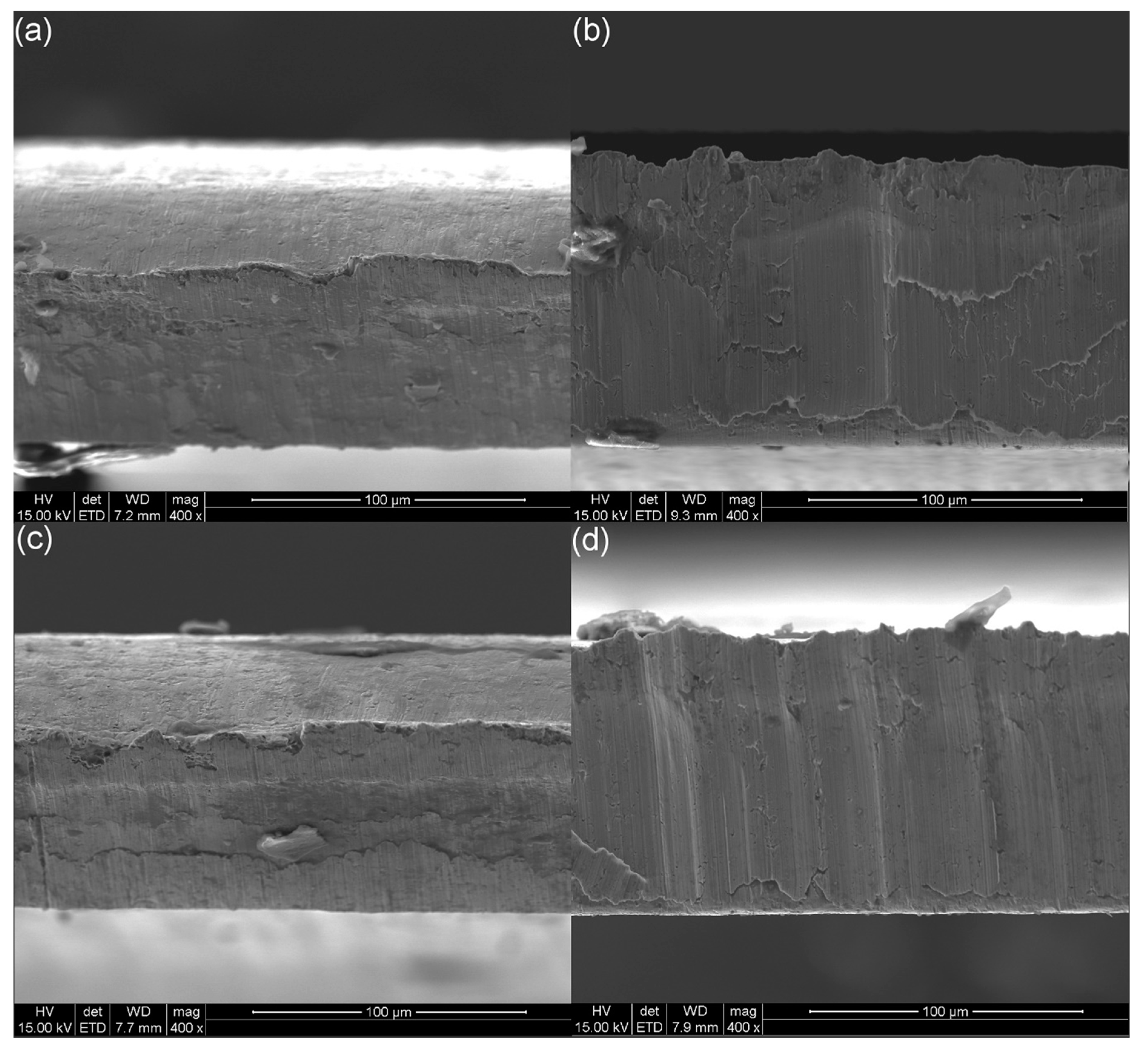
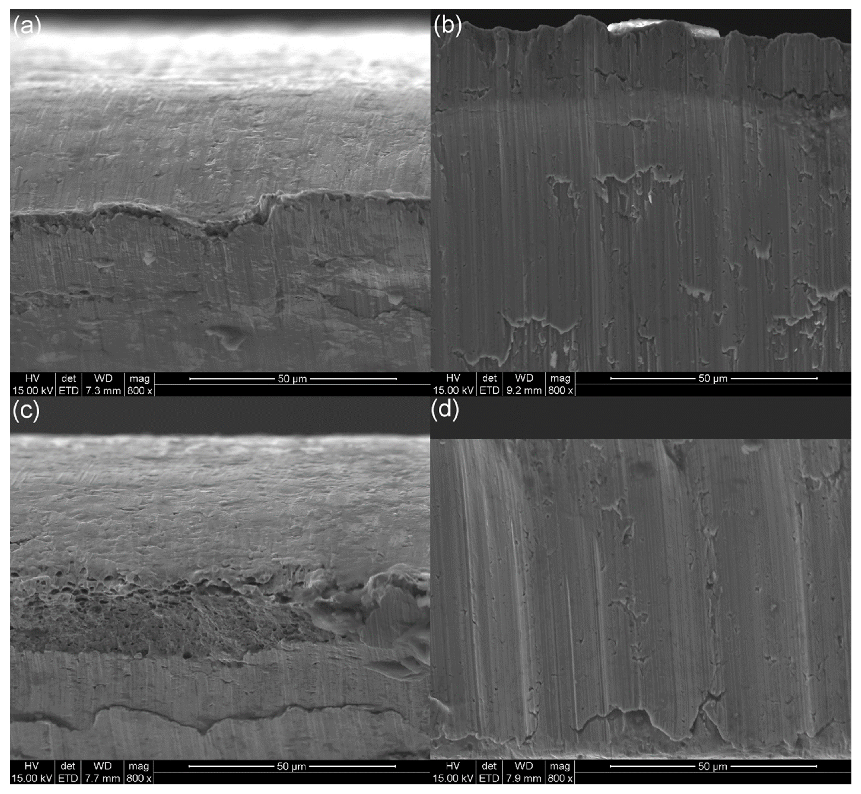
- to obtain the experimental verification of the cutting, microstructural observations of fracture surfaces were performed, the SEM images were obtained using a Zeiss SUPRA 25 (Carl Zeiss AG, Jena, Germany) scanning microscope operating at 20 kV under two different magnifications: 400× and 800×;
- the final stage concerns the comparison of the numerical simulations with the experimental results.
3.1. Material
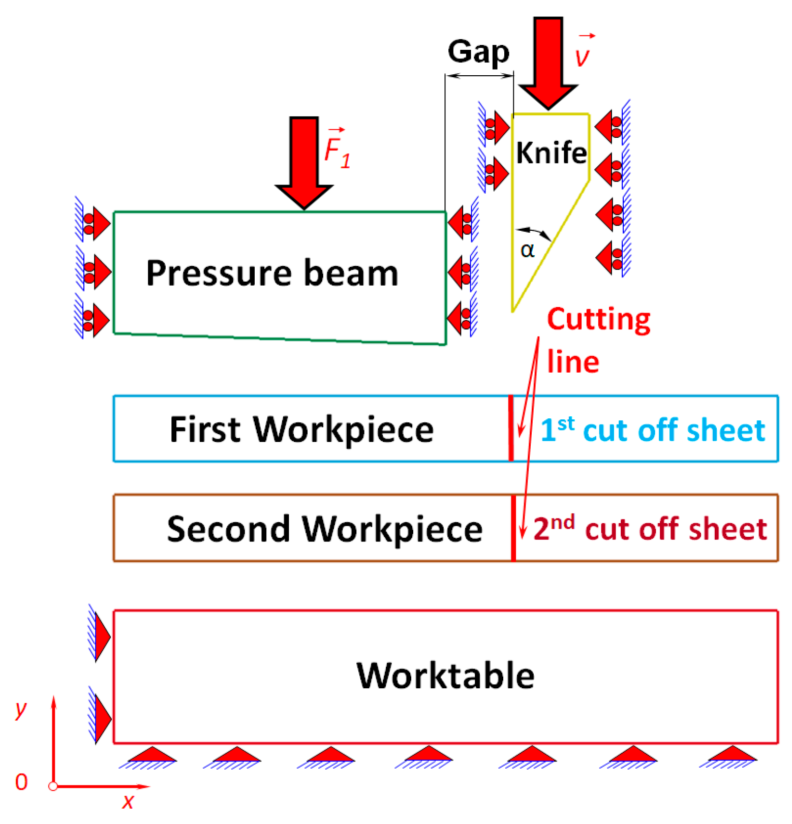
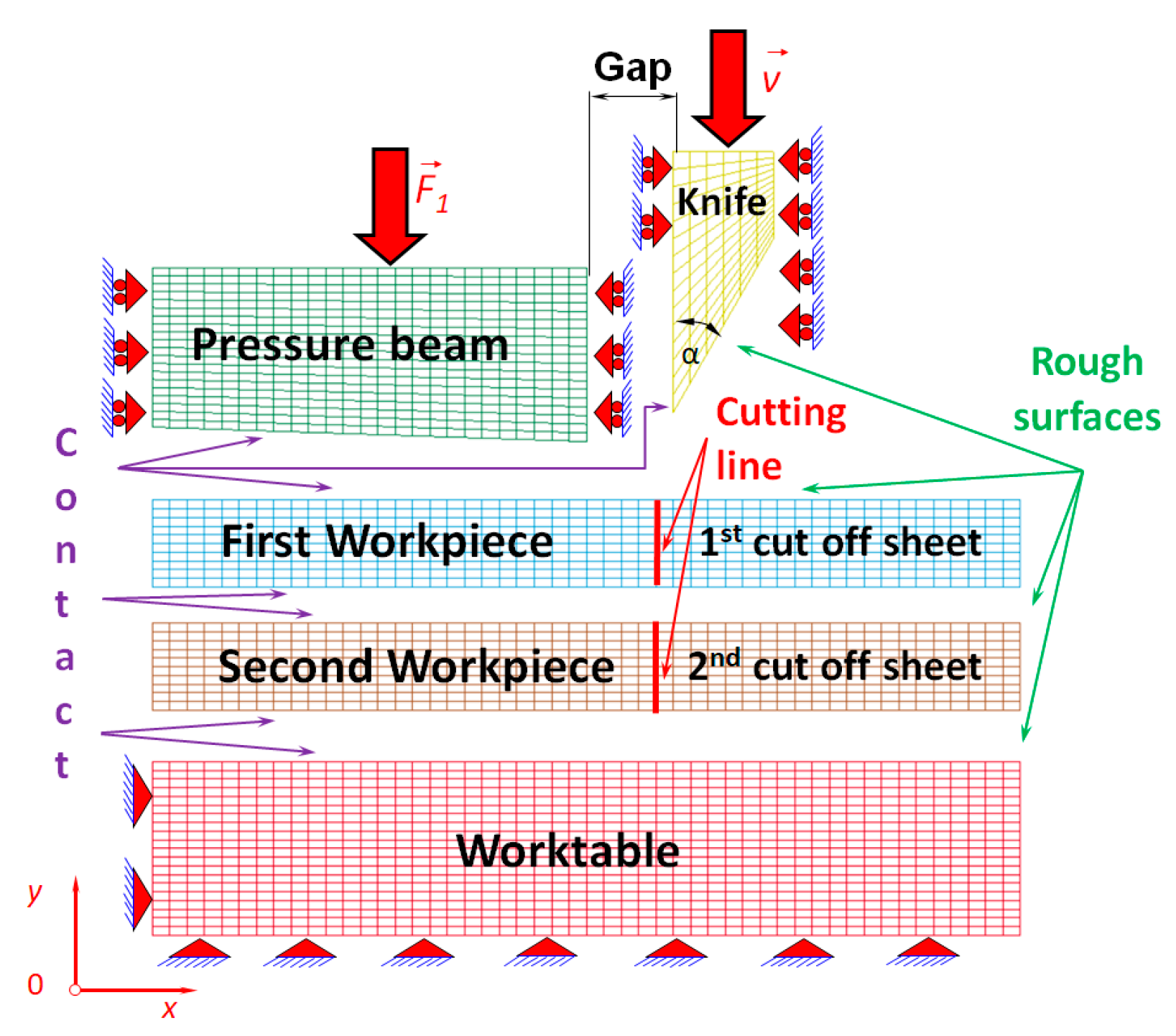
3.2. Physical Model of the Bundle of Sheets
- cutting tool,
- pressure beam,
- bundle of sheets which consists of two separate metal sheets being cut,
- worktable.
- the rigid cutting tool and the first deformable sheet,
- the rigid cutting tool and the second deformable sheet,
- the rigid pressure beam and the first deformable sheet,
- the first deformable sheet and the second deformable sheet,
- the second deformable sheet and the rigid worktable.
- static coefficient of friction µs = 0.22,
- kinetic coefficient of friction µk = 0.11.
3.3. Microscopic Investigations
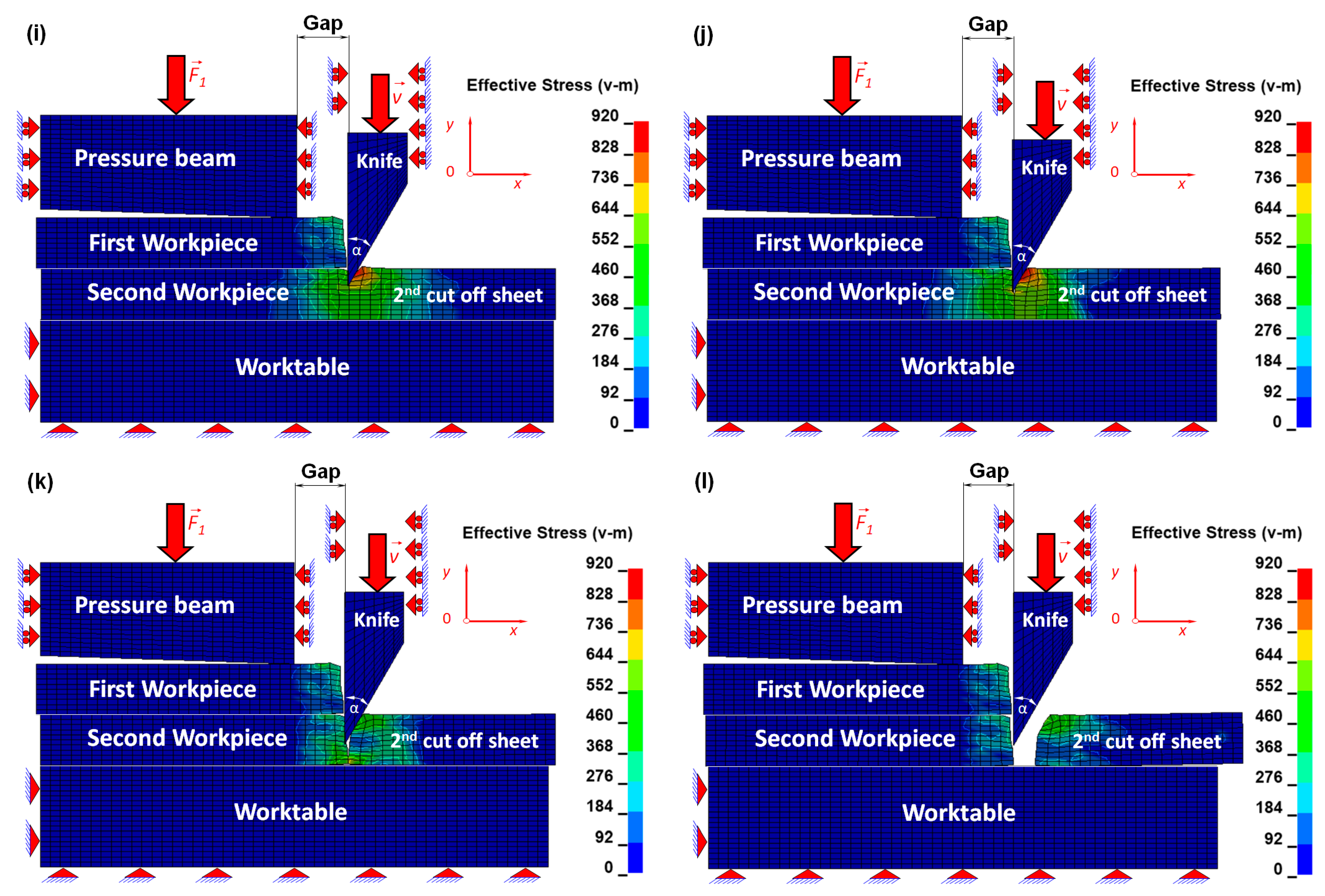
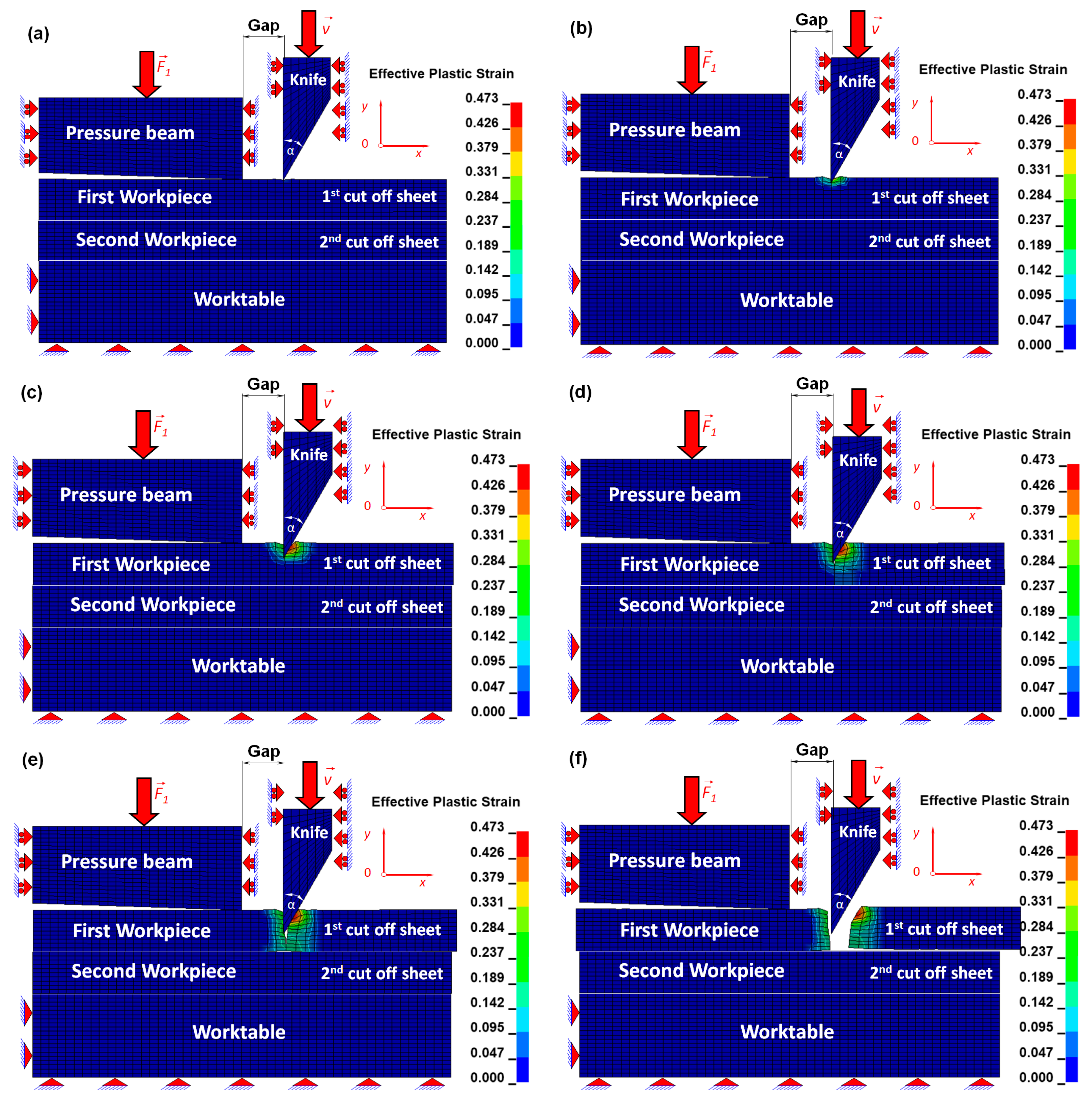
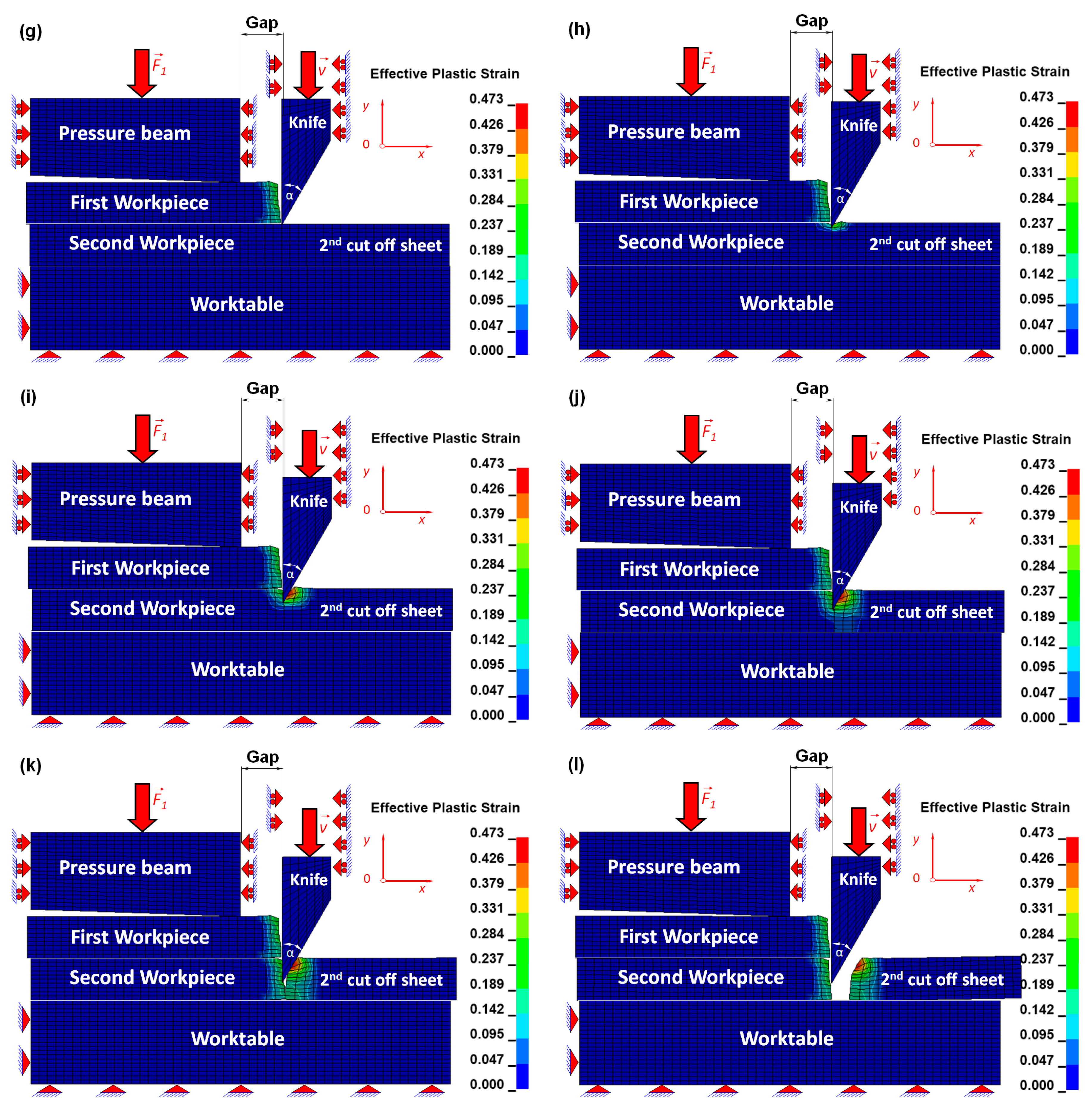
4. Results and Discussion
- the numerical simulations concerning the cutting process of a bundle of sheets,
- the experimental investigations consisting of a series of microstructural images obtained by means of a scanning electron microscope (SEM),
- the comparison of the numerical and experimental results.
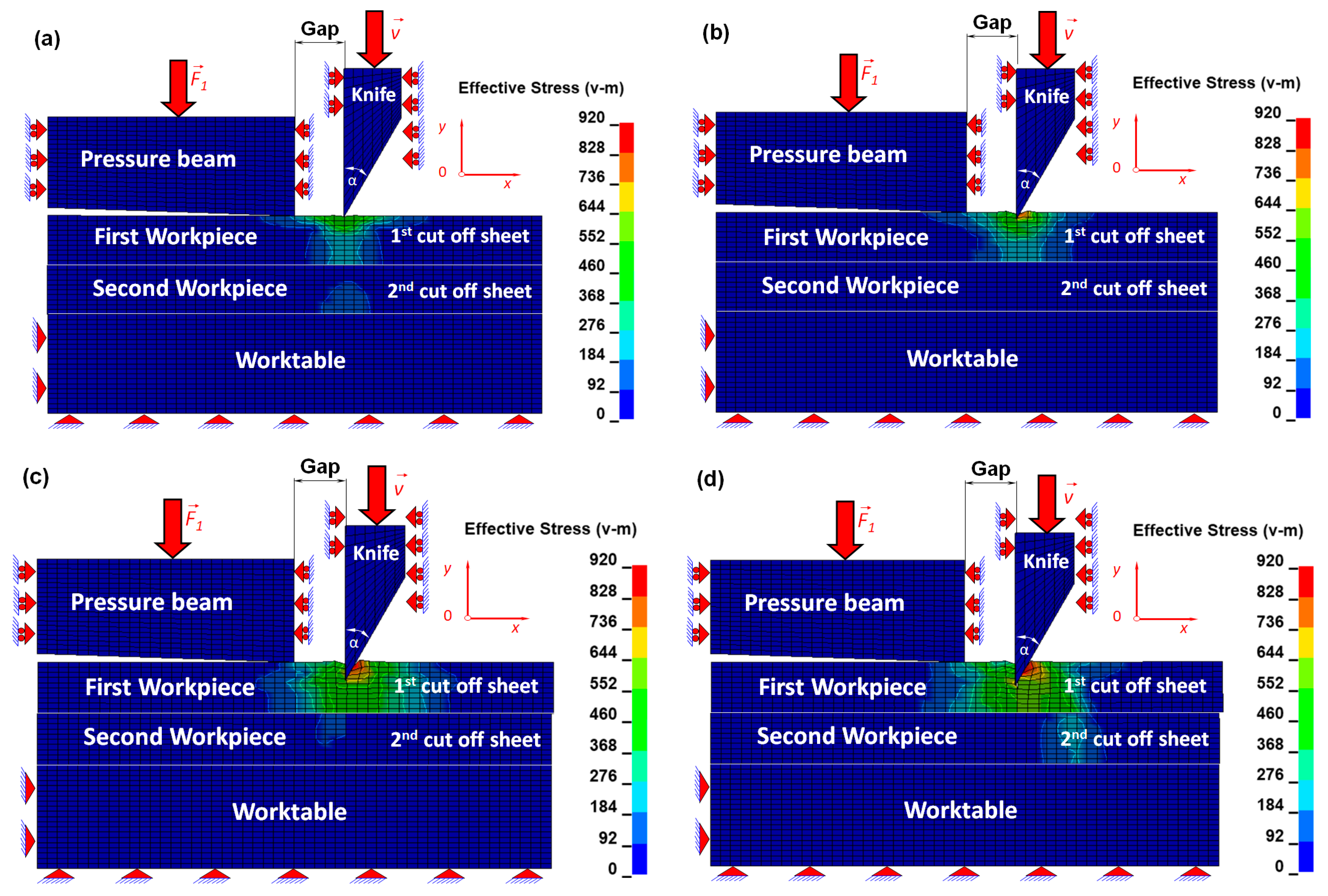
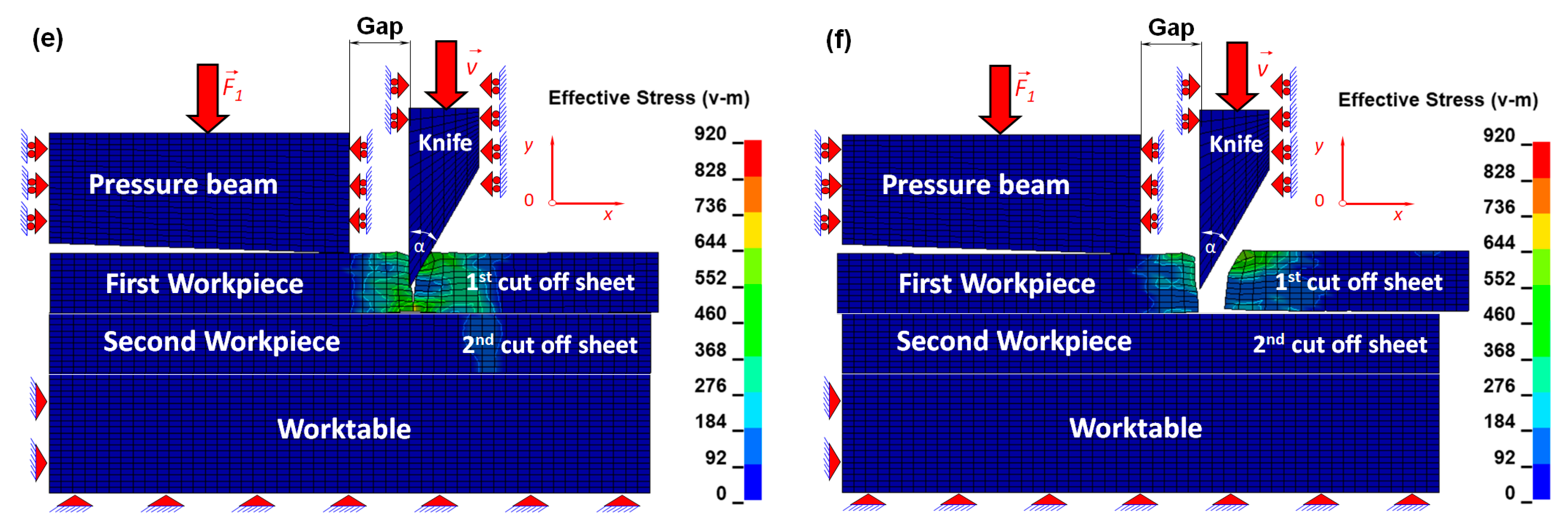
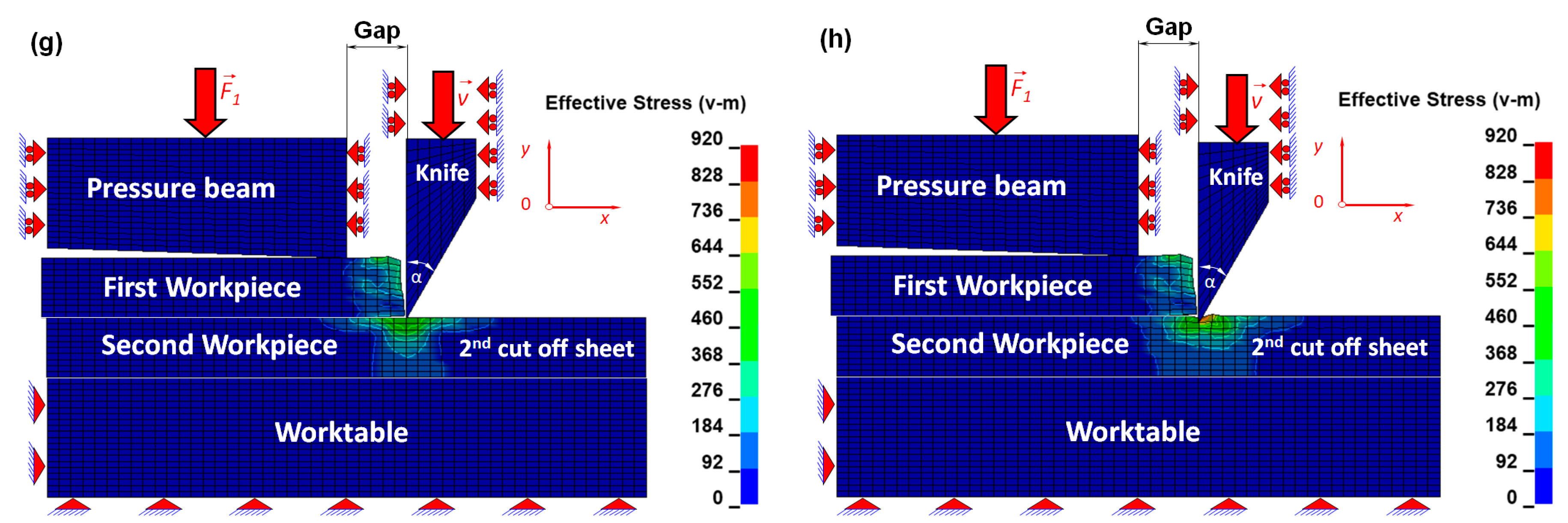
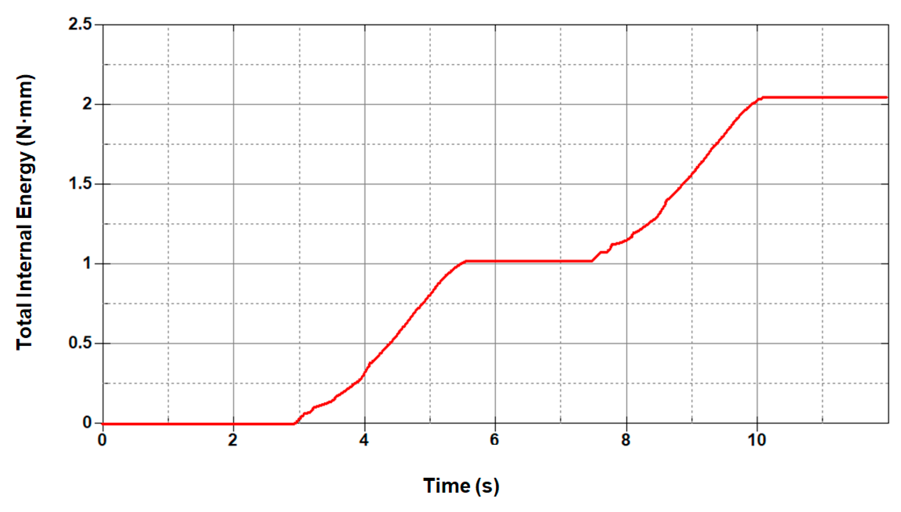
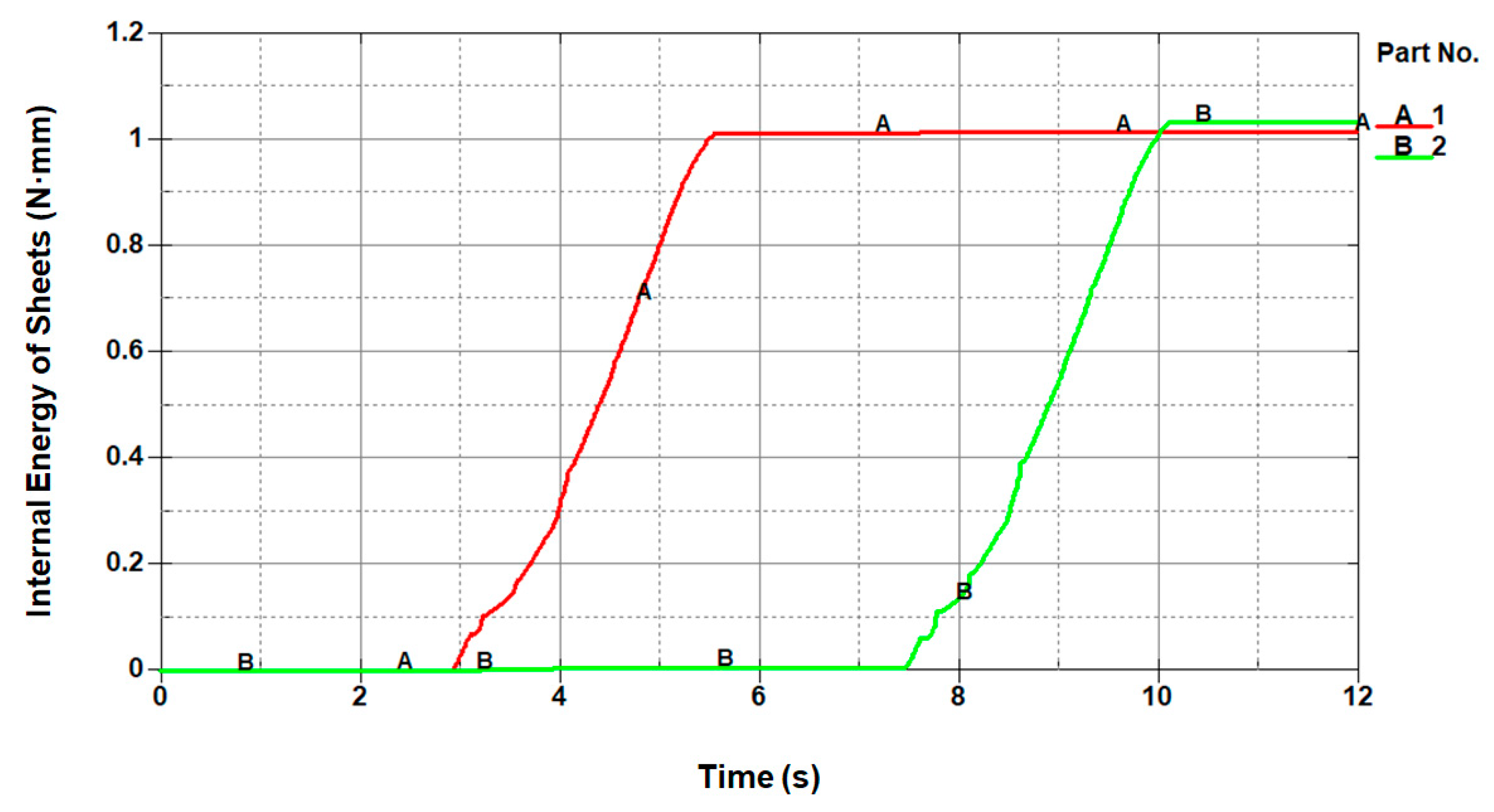
4.1. Numerical Simulations
4.2. Microscopic Details
4.3. Comparison of the Numerical and Experimental Investigations
5. Conclusions
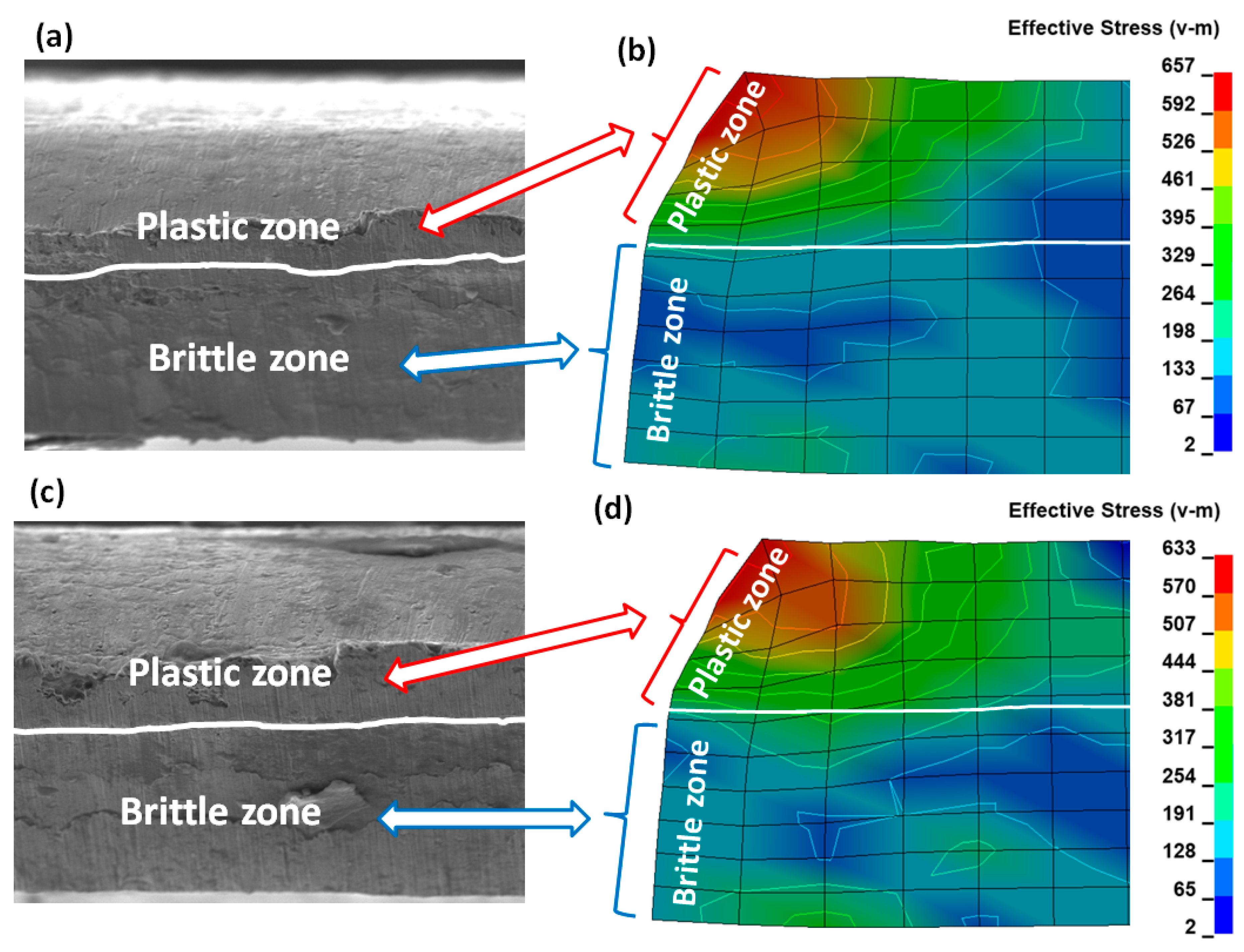
- the maximum stresses and the plastic strains obtained in the numerical simulations are mainly concentrated in sheets being cut close to the tip of the blade of a cutting tool,
- the maximum reduced Huber–Mises stresses in the first stage of cutting are higher than the yield point and that is why sheets being cut cannot withstand it with the result that ductile fracture occurs at a height from zero to circa 1/3 of the height of the sheet being cut measured from the top of the sheets downwards. In this particular ductile zone shearing dominates, justified on the base of numerical as well as experimental data,
- the maximum reduced Huber–Mises stresses in the final stage of cutting are higher even than the ultimate strength which occurs at a height larger than circa 1/3 of the height of the sheets being cut, measured from the top of the sheets downwards. The steel sheet being cut in this particular zone cannot withstand it and brittle fracture occurs because instead of shearing, stretching dominates implied on the basis of numerical simulations and verified by experiment,
- on the basis of SEM imaging it can be stated that ductile fracture is accompanied by many defects like burrs, vertical scratches, higher roughness, larger edge bending, etc.,
- brittle fracture has no significant defects and is characterised by a smooth surface in the cross section of the sheets being cut, observed under the scanning electron microscope.
Author Contributions
Funding
Acknowledgments
Conflicts of Interest
References
- Arslanov, M.Z. A polynomial algorithm for one problem of guillotine cutting. Oper. Res. Lett. 2007, 35, 636–644. [Google Scholar] [CrossRef]
- Alvarez-Valdes, R.; Parajon, A.; Tamarit, J.M. A tabu search algorithm for large-scale guillotine (un)constrained two-d imensional cutting problems. Comput. Oper. Res. 2002, 29, 925–947. [Google Scholar] [CrossRef]
- Tiwari, S.; Chakraborti, N. Multi-objective optimization of a two-dimensional cutting problem using genetic algorithms. J. Mater. Process. Technol. 2006, 173, 384–393. [Google Scholar] [CrossRef]
- Gasiorek, D.; Baranowski, P.; Malachowski, J.; Mazurkiewicz, L.; Wiercigroch, M. Modelling of guillotine cutting of multi-layered aluminum sheets. J. Manuf. Process. 2018, 34, 374–388. [Google Scholar] [CrossRef]
- Nouari, M.; Makich, H. On the Physics of Machining Titanium Alloys: Interactions between Cutting Parameters, Microstructure and Tool Wear. Metals 2014, 4, 335–338. [Google Scholar] [CrossRef]
- Razak, N.H.; Chen, Z.W.; Pasang, T. Effects of Increasing Feed Rate on Tool Deterioration and Cutting Force during and End Milling of 718Plus Superalloy Using Cemented Tungsten Carbide Tool. Metals 2017, 7, 441. [Google Scholar] [CrossRef]
- Koklu, U.; Basmaci, G. Evaluation of Tool Path Strategy and Cooling Condition Effects on the Cutting Force and Surface Quality in Micromilling Operations. Metals 2017, 7, 426. [Google Scholar] [CrossRef]
- Haddag, B.; Atlati, S.; Nouari, M.; Moufki, A. Dry Machining Aeronautical Aluminum Alloy AA2024-T351: Analysis of Cutting Forces, Chip Segmentation and Built-Up Edge Formation. Metals 2016, 6, 197. [Google Scholar] [CrossRef]
- Kaczmarczyk, J.; Grajcar, A. Numerical Simulation and Experimental Investigation of Cold-Rolled Steel Cutting. Materials 2018, 11, 1263. [Google Scholar] [CrossRef] [PubMed]
- Bohdal, Ł. Application of a SPH Coupled FEM Method for Simulation of Trimming of Aluminum Autobody Sheet. Acta Mech. Autom. 2016, 10, 56–61. [Google Scholar] [CrossRef]
- Fedeliński, P.; Górski, R.; Czyż, T.; Dziatkiewicz, G.; Ptaszny, J. Analysis of Effective Properties of Materials by Using the Boundary Element Method. Arch. Mech. 2017, 66, 19–35. [Google Scholar]
- Paggi, M. Crack Propagation in Honeycomb Cellular Materials: A Computational Approach. Metals 2012, 2, 65–78. [Google Scholar] [CrossRef]
- Perez, N. Fracture Mechanics; Kluwer Academic Publishers: Boston, MA, USA, 2004. [Google Scholar]
- González, H.; Pereira, O.; Fernández-Valdivielso, A.; López de Lacalle, L.N.; Calleja, A. Comparison of Flank Super Abrasive Machining vs. Flank Milling on Inconel® 718 Surfaces. Materials 2018, 11, 1638. [Google Scholar]
- Del Pozo, D.; López de Lacalle, L.N.; López, J.M.; Hernández, A. Prediction of Press/Die Deformation for an Accurate Manufacturing of Drawing Dies. Int. J. Adv. Manuf. Technol. 2008, 37, 649–656. [Google Scholar] [CrossRef]
- Lamikiz, A.; López de Lacalle, L.N.; Sanchez, J.A.; Bravo, U. Calculation of the Specific Cutting Coefficients and Geometrical Aspects in Sculptured Surface Machining. Mach. Sci. Technol. 2005, 9, 411–436. [Google Scholar] [CrossRef]
- Kaczmarczyk, J. Numerical Simulations of Preliminary State of Stress in Bundles of Metal Sheets on the Guillotine. Arch. Mater. Sci. Eng. 2017, 85, 14–23. [Google Scholar] [CrossRef]
- Kaczmarczyk, J.; Gąsiorek, D.; Mężyk, A.; Skibniewski, A. Connection Between the Defect Shape and Stresses which Cause it in the Bundle of Sheets Being Cut on Guillotines. Model. Optim. Phys. Syst. 2007, 6, 81–84. [Google Scholar]
- Show, M.C. Metal Cutting Principles; Oxford University Press: New York, NY, USA, 2005. [Google Scholar]
- Bhatti, M.A. Practical Optimization Methods; Springer-Verlag Inc.: New York, NY, USA, 2000. [Google Scholar]
- Rothwell, A. Optimisation Methods in Structural Design; Springer International Publishing AG: Delft, The Netherlands, 2017. [Google Scholar]
- Goldberg, D.E. Genetic Algorithms in Search, Optimization, and Machine Learning; Addison-Wesley Publishing Company, Inc.: New York, NY, USA, 1989. [Google Scholar]
- Michalewicz, Z. Genetic Algorithms + Data Structures = Evolution Programs; Springer: Berlin/Heidelberg, Germany, 1996. [Google Scholar]
- LS-DYNA Keyword User’s Manual; Livermore Software Technology Corporation: Livermore, CA, USA, 2017.
- Bathe, K.J.; Chaudhary, A. A Solution Method for Planar and Axisymmetric Contact Problems. Int. J. Numer. Method Eng. 1985, 21, 65–88. [Google Scholar] [CrossRef]
- Belytschko, T.; Liu, W.K.; Moran, B.; Elkhodary, K.I. Nonlinear Finite Elements for Continua and Structure; John Wiley & Sons, Ltd.: Southern Gate, CA, USA, 2014. [Google Scholar]
- Fish, J.; Belytschko, T.A. First Course in Finite Elements; John Wiley & Sons, Ltd.: Southern Gate, CA, USA, 2007. [Google Scholar]
- Mohammadi, S. Discontinuum Mechanics Using Finite and Discrete Elements; WIT Press Southampton: Boston, MA, USA, 2003. [Google Scholar]
- Hughes, T.J.R. The Finite Element Method. Linear Static and Dynamic Finite Element Analysis; Manufactured in the United States by RR Donnelley: Chicago, IL, USA, 2016. [Google Scholar]
- Zienkiewicz, O.C.; Taylor, R.L. The Finite Element Method, Solid Mechanics; Butterworth-Heinemann: Oxford, UK, 2000. [Google Scholar]
- Timoshenko, S.P.; Goodier, J.N. Theory of Elasticity; McGraw-Hill Education: New York, NY, USA, 2017. [Google Scholar]
- Chaudhary, A.B.; Bathe, K.J. A Solution Method for Static and Dynamic Analysis of Three—Dimensional Contact Problems with Friction. Comput. Struct. 1986, 24, 855–873. [Google Scholar] [CrossRef]
- ASM Handbook. Volume 12: Fractography; ASM International: Cleveland, OH, USA, 1987. [Google Scholar]


| No | Name of the Material Properties | Symbol | Value |
|---|---|---|---|
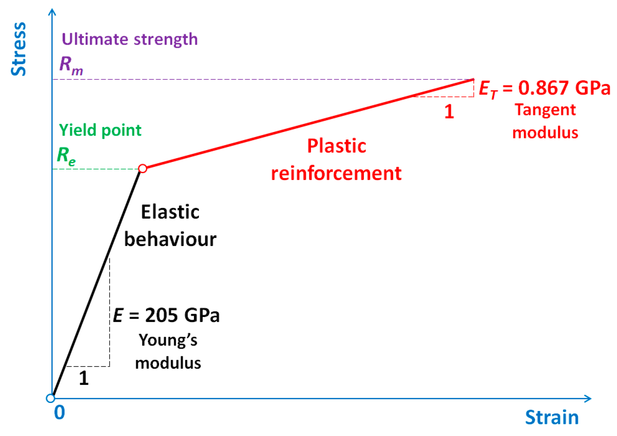
| 1. | Young’s modulus | E | 205 GPa |
| 2. | Poison’s ratio | ν | 0.28 |
| 3. | Kirchhoff’s modulus | G | 80 GPa |
| 4. | Tangent modulus | ET | 0.867 GPa |
| 5. | Failure strain | ɛf | 0.15 |
| 6. | Yield stress | Re | 0.51 GPa |
| 7. | Ultimate tensile strength | Rm | 0.64 GPa |
| No | Name of the Part | Kind of Part | Number of Nodes | Number of Elements |
|---|---|---|---|---|
| 1. | Cutting tool (knife) | Rigid | 112 | 90 |
| 2. | First metal sheet being cut | Deformable | 572 | 500 |
| 3. | Second metal sheet being cut | Deformable | 572 | 500 |
| 4. | Pressure beam | Rigid | 546 | 500 |
| 5. | Worktable | Rigid | 1071 | 1000 |
| Total number | 2873 | 2590 | ||
© 2019 by the authors. Licensee MDPI, Basel, Switzerland. This article is an open access article distributed under the terms and conditions of the Creative Commons Attribution (CC BY) license (http://creativecommons.org/licenses/by/4.0/).
Share and Cite
Kaczmarczyk, J.; Kozłowska, A.; Grajcar, A.; Sławski, S. Modelling and Microstructural Aspects of Ultra-Thin Sheet Metal Bundle Cutting. Metals 2019, 9, 162. https://doi.org/10.3390/met9020162
Kaczmarczyk J, Kozłowska A, Grajcar A, Sławski S. Modelling and Microstructural Aspects of Ultra-Thin Sheet Metal Bundle Cutting. Metals. 2019; 9(2):162. https://doi.org/10.3390/met9020162
Chicago/Turabian StyleKaczmarczyk, Jarosław, Aleksandra Kozłowska, Adam Grajcar, and Sebastian Sławski. 2019. "Modelling and Microstructural Aspects of Ultra-Thin Sheet Metal Bundle Cutting" Metals 9, no. 2: 162. https://doi.org/10.3390/met9020162
APA StyleKaczmarczyk, J., Kozłowska, A., Grajcar, A., & Sławski, S. (2019). Modelling and Microstructural Aspects of Ultra-Thin Sheet Metal Bundle Cutting. Metals, 9(2), 162. https://doi.org/10.3390/met9020162