Abstract
High-velocity impact welding is a kind of solid-state welding process that is one of the solutions for the joining of dissimilar materials that avoids intermetallics. Five main methods have been developed to date. These are gas gun welding (GGW), explosive welding (EXW), magnetic pulse welding (MPW), vaporizing foil actuator welding (VFAW), and laser impact welding (LIW). They all share a similar welding mechanism, but they also have different energy sources and different applications. This review mainly focuses on research related to the experimental setups of various welding methods, jet phenomenon, welding interface characteristics, and welding parameters. The introduction states the importance of high-velocity impact welding in the joining of dissimilar materials. The review of experimental setups provides the current situation and limitations of various welding processes. Jet phenomenon, welding interface characteristics, and welding parameters are all related to the welding mechanism. The conclusion and future work are summarized.
1. Introduction
Welding technique has wide applications in the areas of aerospace, automobiles, shipbuilding, pressure vessels, and bridges. It is one of the important manufacturing methods in industries. Based on the state of materials during the welding process, welding techniques are categorized as solid-state welding and fusion welding [1]. In fusion welding, metallurgical bonding occurs during the solidification of materials. In solid-state welding, metallurgical bonding occurs below the melting point of materials. Therefore, defects such as solidification cracking, distortion, and porosity [2], which appear in fusion welding as a result of the liquid phase, can be avoided in solid-state welding. Solid-state welding has a long history that predates the invention of arc welding. Ancients used hammers to weld gold earlier than 1000 B.C., which today is called forge welding. Since the early 20th century, the development of solid-state welding has been limited due to arc welding being easier than forge welding and having a higher efficiency.
The advantages of joining dissimilar and other specific materials, such as Al 7075 alloy, titanium, and zinc-coated sheet steels [3], brought solid-state welding back onto the stage. For example, the joining of steel and copper provides good electric conductivity and mechanical properties; the joining of steel and aluminum reduces the weight of automobile [4]. Dissimilar materials usually have different thermal conductivity, thermal expansion coefficients, and melting points, which may result in defects in fusion welding [5,6,7]. Furthermore, some specific alloys are sensitive to heat. Both Al 7075 alloy and titanium are important materials in aerospace and aircraft. However, Al 7075 alloy is susceptible to hot cracking [8,9], and titanium is chemically active at high temperature [10,11,12]. Zinc-coated steel is an important structural material in automobiles. However, during the fusion-welding process, zinc vaporizes, and porosity forms when zinc vapor is trapped.
Various solid-state welding methods have been developed recently, for example, friction stir welding, explosive welding (EXW), friction welding, magnetic pulse welding (MPW), cold welding, ultrasonic welding, roll welding, pressure gas welding, resistance welding, vaporizing foil actuator welding (VFAW), gas gun welding (GGW), and laser impact welding (LIW). Among those solid-state welding methods—GGW, EXW, MPW, VFAW, and LIW—are five kinds of high-velocity impact-welding methods. They shared the same welding mechanism, but have different welding energy sources indicated by their names: high-speed gas [13], explosive [14,15], capacitor bank energy (MPW and VFAW) [16], and laser [17], respectively.
High-velocity impact welding is characterized by a low welding temperature and fast welding speed. The process is conducted at room temperature. Furthermore, there is no external heat input during the welding process. Figure 1 is a schematic transient state in the welding process. After the transient force is applied on the external surface of the flyer, the flyer moves toward the target at the velocity of several hundred meters per second [18]. When the flyer collides on the target, a jet is generated at the collision point, which contains contaminants, oxide layers, and a thin layer of metals. As a result, the “clean” metals (no contaminants, oxide layers) are exposed to each other. With the transient force, they are brought within atomic distance, where the atomic bond is formed. This process is usually takes several to dozens of microseconds based on different welding processes. For example, in LIW, it usually takes less than one microsecond. In other high-velocity impact-welding processes, it takes longer than that.

Figure 1.
A transient state of bonding interface in high-velocity impact welding, reproduced from [19], with permission from Roral Society, 1934.
In this review, five high-velocity impact-welding methods and the corresponding welding mechanisms are reviewed in Section 2. In Section 3, the macro-characteristics and micro-characteristics of the bonding interface associated with weld quality are summarized. In Section 4, the welding parameters that may affect the welding quality are discussed, such as for example, the material properties, impact velocity, impact angle, and surface preparation. At the end, conclusions and future work are addressed based on the discussion of welding mechanisms, bonding interfaces, and welding parameters.
2. Welding Methods and Jet Phenomenon
2.1. Overview of High-Velocity Impact-Welding Methods
Nowadays, five high-velocity impact-welding methods have been developed, which are GGW, EXW, MPW, VFAW, and LIW. GGW was limited to the lab research on welding parameters and welding mechanisms. EXW experienced decent studies, and has been widely applied in manufacturing all over the world. MPW has limited application in automobiles, and is under development all over the world. VFAW studies have been mainly conducted by researchers from Ohio State University, and are in the transition state from lab research to industrial application. LIW was proposed recently, and is under lab research.
2.1.1. Explosive Welding and Gas Gun Welding
EXW is the first high-velocity impact-welding method. It was observed when a projectile was fired by explosives and collided on another metal surface [20]. However, there was no record of EXW until the First World War. Its rapid development and wide application in industries was in the middle of the 20th century. The first United States (U.S.) patent filed by Philipchuk et al. in 1962 [21]. As its name suggests, explosives detonation is implemented to provide the impact force for the flyer. It was reported that more than 200 material combinations have been successfully welded by EXW [22], for example, Fe/Ti [23,24,25], Zr/Fe [26], Al/Ti [27], Ti/Ni [28], and Al/Fe [29,30]. For plate welding, two generally used experimental setups are the inclined mode and parallel mode, as shown in Figure 2. Buffer was used to avoid severe damage to the flyer by explosives. The inclined setup came from the idea of hollow charge (which is introduced later); it was used earlier than parallel setup. α was the initial angle in the inclined mode. Since it was not capable of handling large sheet metal, the parallel setup was developed later, and was mainly used to weld large plates with a pre-determined standoff distance. In the parallel setup, the impact angle varies with different standoffs. EXW was also used for the cladding of tubes [15]. From a two-dimensional observation, the experimental setup for tube cladding or ring to tube welding involves the parallel mode for plate welding curved into a circle. In EXW, it is difficult to measure the impact velocity directly, if it is at all possible. Usually, the explosive detonation velocity is measured [31].
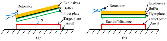
Figure 2.
Schematic experimental setups of explosive welding (EXW): (a) inclined; (b) parallel.
Since EXW is not easy to conduct within the laboratory, GGW is usually used to study the welding parameters and welding mechanism for EXW. In GGW, the flyer is accelerated by high speed and high-pressure gas to collide on the target. Botros and Groves provided an impact force for the flyer with high-pressure gas from burning gunpowder in a 76-mm powder cannon gun [32]. Later on, compressed helium was used since it is clean and easy to control. In GGW, the initial angle is preset either on the flyer or target. The impact velocity can be measured with a high-speed camera [32] and electrical circuit [33]. The resolution of the high-speed camera was not enough to record the welding process accurately, because the welding process is usually done within several microseconds. In the electrical circuit method, there was a corresponding voltage change in this electrical circuit when wires were cut successively by the flyer. The time between the voltage change was then recorded to calculate the impact velocity [34]. The effect of the wires’ transient block on impact velocity and impact angle has not yet been investigated.
EXW has been applied in industries all over the world. The Dynamic Materials Corporation is a world-leading explosive metalworking business. EXW has been successfully applied in the energy area. Its main application includes heat exchangers, as well as upstream and downstream products, in the oil and gas industries.
2.1.2. Magnetic Pulse Welding
MPW was used in Russia in the 1960s for the first time to weld an end closure for nuclear fuel rod holders [35,36]. The application of MPW is mainly tubular, for example, joining between tubes or tubes and cylinders. Currently, the most common application of MPW in industry is driveshaft production in the company of Pulsar and Dana [37]. MPW didn’t experience a rapid development and wide application as EXW until recently due to the slow development of equipment [37]. Metal combinations of Cu/Cu [38], Cu/brass [39], Cu/Al [40], Cu/Fe [41], Al/Al [18], Al/brass [39], Al/Mg [42,43,44], Al/Fe [36,45,46,47,48], Al/ bulk metallic glass [49], and plastic/Al [50] etc. have been investigated. The general weld configurations of MPW are the lap joint and butt joint. MPW doesn’t require a skilled operator. In addition, the welding parameters of MPW are controlled separately to permit fully exploring the effect of welding parameters over a wide range.
In MPW, the flyer is driven by electromagnetic force to collide on the target. The MPW system includes a capacitor bank, coil actuator, the flyer, and the target. The capacitor bank is the energy source of MPW. It is an open electrical circuit of inductance, resistance, and capacitance. The closed circuit was formed by the connection between the capacitor bank and coil actuator, which is made of electrical conductive materials. With the high-speed switch on, the capacitors begin to charge. The primary current passes through the actuator; thus, a changing magnetic field is around the actuator that interacts with any metals within it. Consequently, a secondary current with the opposite direction of the primary current is induced in the flyer. Simultaneously, the flyer is expelled by the electromagnetic force to collide on the target. A typical primary current and the flyer velocity, as measured by a Rogowski coil and photon Doppler velocimetry, are shown in Figure 3. The rise time is an important factor to relate impact velocity. The shorter the rise time, the higher the impact velocity will be.
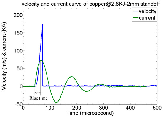
Figure 3.
Typical primary current and flyer velocity in magnetic pulse welding (MPW).
Figure 4 shows schematic experimental setups for MPW with different coil actuators. A solenoid coil actuator is used for tube-to-tube welding (Figure 4a). Figure 4b shows the experimental setup with a uniform pressure actuator (UPA) for plate-to-plate welding. The UPA was initially designed for magnetic pulse forming at Ohio State University [51]. The wires between the flyer and the target form an impact angle during the welding process. The three types of bar actuators are I-shaped, U-shaped, and E-shaped (Figure 4c–e); they were developed by Kore et al. in India [52,53], Zhang et al. in the U.S. [54] and Aizawa et al. in Japan [45], separately. The thinner bar is used to push the flyer for U-shaped and E-shaped actuators. If an I-shaped bar and the thinner bars have the same dimension, an E-shaped actuator brings more inductance into the circuit. The rise time becomes longer. Currently, MPW is limited to lap joints. Experimental setups for other types of welding should be developed in the future.
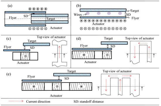
Figure 4.
Schematic experimental setups for magnetic pulse welding (MPW) with various actuators: (a) solenoid coil actuator for tube-to-tube welding; (b) uniform pressure actuator for plate-to-plate welding; (c–e) I-shaped actuator, U-shaped actuator, and E-shaped actuator for plate-to-plate welding.
2.1.3. Laser Impact Welding
The first U.S. LIW patent was filed in 2009 by Daehn and Lippold from Ohio State University [55]. The welding system consists of a laser system, confinement layer, ablative layer, flyer, and target [17]. A laser beam ablates the ablative layer into plasma. With the confinement layer, the expansion of the plasma pushes the flyer to collide on the target. Materials such as copper, aluminum, steel, and titanium were welded with the LIW method [18,56,57]. The current experimental setup is similar to that for EXW, as shown in Figure 2. The possible industry application setup was proposed by Wang et al. [17]. In their study, the effect of the confinement layer, ablative layer, and the connection between the flyer and confinement layer were investigated for industrial application. The current weld configuration is limited to spot welding. In the study of Liu et al., they proposed the flyer movement with a Gaussian laser beam for laser spot welding. The central part of the spot was not welded, while welding occurred around the circumferential direction. The same phenomenon was also observed by Wang et al. [58], who also simulated the welding process with the smooth particle hydrodynamics (SPH) method [59] and reproduced the spalling and rebound phenomena by the simulation. For LIW, the spalling and rebound phenomena should be further studied in order to propose ways for the procedures to avoid those two behaviors. The welding area within the laser spot should be further increased. One of the possible future applications of LIW is the welding between Al and Ti in the heart pacemaker.
2.1.4. Vaporizing Foil Actuator Welding
VFAW utilizes the expanding plasma from the vaporization of thin foils to push the flyer to move toward the target. The development of VFAW before 2013 was summarized in [60]. In recent studies, the energy for the vaporization of thin foils is from the capacitor bank. The foil was designed in a dog-bone shape in order to concentrate the transient current from the capacitor bank to vaporize the foil. Vivek pointed out that the aluminum foil provided better mechanical impulse than copper foil through its rapid vaporization. Materials such as steel, aluminum, titanium, copper, magnesium, bulk metallic glass, etc., have been successfully welded with VFAW [61,62,63,64,65]. The original experimental setups in VFAW were similar to those used in EXW. The issue with those experimental setups was that the central part of the impacted region was not welded due to the rebound behavior of the flyer. The welds are very narrow. With this experimental setup, the impact angle was formed due to the standoff between the flyer and the target. Upon collision, the edge of the flyer was kept static, while the central part of the flyer moved toward the target. The impact angle was formed when the flyer collided on the target. However, unlike in EXW, in which the flyer gradually contacted with the target from one end to the other, in VFAW, the collision between the flyer and the target were at the same time. Thus, non-continuous metallurgical bonding resulted on the collision interface. By studying the effect of the impact angle on metallurgical bonding, the target was designed with grooves, which have different angles. The angle range for wave formation along the collision interface was proposed as 8–24° for 3003 Al and 4130 steel [64], and 16–24° for 3003 Al and pure Ti [61]. The recorded maximum impact velocity for VFAW was 900 m/s [66]. As for the numerical simulation, the finite element method with Eulerian formalism is a suitable way to predict the morphology of the collision interface in high-velocity impact welding [67]. The main possible application of the VFAW process is in the automobile industries. Researchers at Ohio State University are investigating its application in the car frame.
2.2. Jet Phenomenon
Jet is the essential reason for welding to occur in the high-velocity impact-welding process. In high-velocity impact welding, a jet is generated by the high-velocity oblique impact of the flyer and target, and then rapidly flies away. Without the impact angle, the jet would be trapped between the collision interfaces. Therefore, the impact angle is one of the significant parameters in order for metallurgical bonding to occur. It is commonly believed that the jet consists of thin metal layers, oxide layers, and other contaminants from the colliding surfaces of the flyer and the target [1]. After the jet flies away, clean virgin metal surfaces are generated. The surfaces are then brought together to a distance within the atomic scale by a transient high-impact pressure. As a result, the atomic bond is produced between the contact area of the flyer and the target. The jet phenomenon has been studied by several researchers [68,69]. In EXW, some welding parameters are applied to predict the jet generation. There is continuous jet formation in EXW due to the collision between the flyer and the target moving from one end to the other end continuously with the detonation of explosives. In other high-velocity impact-welding processes, the continuous generation of the jet along the collision interface is an issue to be resolved by the optimization of an experimental setup design.
The phenomenon in which explosives with a cavity in contact with a steel plate can make a deeper hole in the steel ahead of it than explosives without a cavity has been known for more than 200 years. This phenomenon is called hollow charge. Regarding the study of hollow charge, the phenomenon that explosives with a cavity lined with thin metal layers have enormous penetration ability was discovered around 1948. Birkhoff et al. studied the powerful penetrating and cutting phenomenon of hollow conical liners and hollow wedge-shaped liners (cross-section shown in Figure 5), respectively. As shown in Figure 5b, a high pressure from the detonation of explosives was applied on the outer wall of the wedge, causing it to collapse inward. Figure 5c shows the geometry of the collapse process of the metal liner: α is the initial angle that was set before the experiment; β (β ≠ 0) is the dynamic angle (impact angle) that was formed during the experiment; V0 is the velocity of the metal liner (impact velocity); V1 (Vw) is the welding velocity in explosive welding; Vd is the detonation velocity of the explosives. The metal liner became two parts at the collision: slug and jet. The jet was from the inside of the metal liners, and the slug was from the outside of the metal liners. Birkhoff et al. [68] proved that the jet was the one with strong penetration ability. This is the first time that the jet phenomenon was studied in detail. It proved that the oblique collision between materials resulted in jet formation on the collision interfaces.
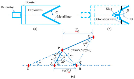
Figure 5.
Hollow charge with wedge-shaped metal liner: (a) prior to the detonation, and (b) during the detonation; and (c) the geometry of the collapse process of the metal liner.
The geometry of the collapse process of the wedge-shaped metal line was adopted in EXW to build the math relationship between the welding parameters later on. The mathematic model to predict the velocity and the mass of the jet was built when V2 is subsonic [19,70]. Cowan and Holtzman studied the limiting conditions for jet formation when V2 is supersonic, and pointed out that a minimum impact angle should be satisfied for jet formation when V2 is supersonic [69]. V2 is the main entrance jet velocity under the assumption that the metal collision is the fluid-like flow.
However, the limitation of their model should be discussed. The pre-condition for their model is the fluid-like flow metal behavior. In their study, the metal was treated as fluid, but they didn’t quantitatively clarify what the requirement was for that pre-condition. They assumed that the shear strength of the metals was negligible compared with the impact pressure from the explosives. Furthermore, in the study of Birkhoff et al. [68], a jet was always generated regardless of the other conditions. Actually, the pressure at the collision point should be high enough for the deformation of materials into a jet [22]. In other words, their model couldn’t predict whether a jet will happen or not. Although the mechanism of jet generation has not been fully understood, the existence of a jet and the role of a jet in high-velocity impact welding have been generally accepted. As stated earlier, the penetration phenomenon of explosives with a cavity with a metal liner on the armor plate or concrete walls is direct evidence for the existence of a jet. The existence of a jet was also proved using radiographs according to Birkhoff et al. [68]. The existence of a jet was also verified by gas gun welding in which mass of the flyer and target can be measured accurately. Mass comparison before and after the welding has shown that the loss of mass should equal the mass of the jet. In the recent studies regarding the welding mechanism, the research has focused on the effect of the welding interface characteristics, weldability window, and welding parameters on the weld quality. However, jet formation should be studied further due to the continuous metallurgical bonding along the collision interface relying on the continuous generation of the jet, especially for MPW, VFAW, and LIW.
3. Bonding Interface Characteristics
In welding engineering, a welded zone with high strength, good toughness, and enough hardness is desirable. However, in reality, the welded zone is usually weakest welded part, since the microstructure at the welding zone keeps evolving during the welding process. Some defects may appear at the welded zone during the welding process. Therefore, it is necessary to study the bonding interface characteristics in high-velocity impact welding.
3.1. Macrocharacteristics
In high-velocity impact welding, regarding the geometric shape of the bonding interface, straight interface and wave interface (with or without vortices) have been observed [4,71,72], as shown in Figure 6. The wave interface was thought to be not only one of the typical characteristics, but also the sign of metallurgical bonding in EXW for a long time: since the invention of EXW. Recently, Behcet Gulenc [73] also believed that metallurgical bonding should be with a wave interface based on experimental results in which welded samples were characterized by a wave interface, while welded samples with a straight interface were not. However, the observation of a straight interface in some of the explosive-welded materials [71,72,74] demonstrated that a wave interface was not necessary in order for metallurgical bonding to occur. Furthermore, it has been established that the morphology of the bonding interface changed in the order of a straight interface, wave interface without vortices, and wave interface with vortices with the increase of impact pressure/impact velocity [4,14,74,75,76,77] in high-velocity impact welding. In addition, the wavelength and amplitude of the wave interface increased with the increase of the impact pressure/impact velocity once the wave interface formed [73,78,79]. The wavelength and amplitude of the wave interface were also related to the impact angle [62]. They also reported that the wavelength and amplitude of the wave interface was affected the flyer thickness. The bonding interface characteristics were also related to the base material properties [31]. In high-velocity impact welding, a collision interface characterized by a wave with vortices is usually accompanied by a melting phenomenon [80]. Previous studies have concluded that a wave is not essential in order for metallurgical bonding to occur in high-velocity impact welding.
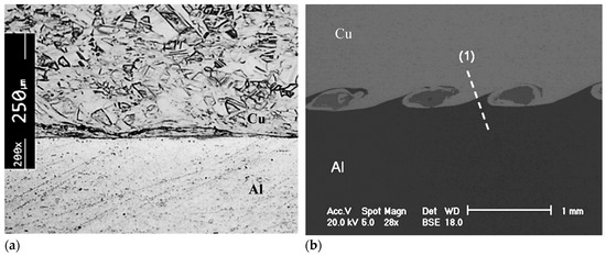
Figure 6.
Bonding interface in high-velocity impact welding: (a) straight interface, reproduced from [81], with permission from Elsevier, 2016; (b) wave interface with vortices, reproduced from [18], with permission from Elsevier, 2011.
Wave interface and straight interface were also studied in relation to aspects of the mechanical properties, such as hardness and tensile strength. In one study that compared a straight interface and wave interface (Al/mild steel bonding interface), a higher hardness was detected near the bonding interface for both types of interfaces. By tensile test, it was demonstrated that a straight interface was stronger than a wave interface [71]. For welded samples with straight interfaces, fracture occurred at the Al side, and for welded samples with wave interfaces, fracture occurred at the welded zone. However, for welded samples with wave interfaces, the fracture mode was brittle. The brittle fracture of the welded sample with a wave interface indicated in a tensile test that there might be continuously distributed brittle phases along the bonding interface, which caused the fracture at the welded zone. Furthermore, some other researchers believed that a wave interface was better than a straight interface because of interlocking or mechanical locking [82,83]. In order to figure out which one is better, experiments should be done very carefully to find out the transition from a straight interface to a wave interface. The maximum strength should be within the transition range in which there is no continuous melting along the collision interface and interlocking played a role to increase the weld strength.
3.2. Microstructure at Bonding Interface
In high-velocity impact welding, two other types of interfaces were observed based on the composition variation across the bonding interface: a sharp interface [4,18,74,84] and a transition layer interface [34,36,40,43,49,75,85,86,87]. These both appeared periodically along the same wave interface with vortices. The transition layer interface was present at vortices where there was melting, and the sharp interface was present at other places along the bonding interface. It is generally accepted that a sharp interface is the result of a solid-state bond. However, it is not clear whether the transition layer interface is a solid-state bond or fusion bond. At the transition layer interface, defects (microvoids) and a crystal structure change (amorphous material) were also observed in some of the welded samples. Therefore, some researchers stated that a transition layer interface was the result of melting and solidification. However, others have argued that welding occurs by a solid-state bond at the transition layer interface where only compositional change happened, such as in cold-pressure welding. Previous studies have indicated that the transition layer interface could be the result of a solid-state bond and a fusion bond, or a mixture of both along the same collision interface, which relies on the welding parameters.
3.2.1. Grain Refinement
Grain refinement was reported along both types of metallurgical bonding interface [74,75,88,89]. In the study of the Al/Al metallurgical bonding interface, both fine and elongated grains were observed by Zhang et al. with the electron backscattered diffraction method (EBSD) [83]. They believed that grain refinement was the result of plastic deformation. They argued if it resulted from melting and solidification, grains with epitaxial orientation should be observed. However, Grignon et al. observed microvoids at the bonding interface of Al/Al beside grain refinement. They stated that grain refinement was the result of melting and solidification [90]. Therefore, both mechanisms for grain refinement are possible in high-velocity impact welding. In this specific experiment, the grain refinement mechanism should be based on the conversion of the kinetic energy of the flyer to heat. However, different mechanisms resulted in different mechanical properties. Severe plastic resulted in grain refinement that brought a high-stress concentration along the welding interface, whereas melting resulted in grain refinement that relieved the stress concentration.
3.2.2. Intermetallics, Microvoids, and Amorphous Materials
The characteristics of the Ti/steel metallurgical bonding interface were studied by Inal et al., Nishida et al., and Kahraman et al. [76,82,87]. Higher hardness was detected at the bonding interface by Inal et al. and Kahraman et al. [76,82]. Regarding the tensile test, welded samples failed out of the welded zone in the study of Inal et al. and Kahraman et al., while in the study of Nishida et al., failure occurred within the welded zone [87]. In the studies of Inal et al. and Kahramen et al., neither melting voids nor intermetallics were found along the bonding interface. However, the existence of an amorphous material was proved by a TEM diffraction pattern in the study of Nishida et al. The authors stated that the amorphous materials were the result of melting and rapid solidification. Therefore, those study indicated that melting in the bonding interface lowered the mechanical properties.
Ben-Artzy et al. and Kore et al. studied the bonding interface of Al/Mg [42,43]. Ben-Artzy et al. believed that bonding between aluminum and magnesium was the result of melting and solidification, while Kore et al. thought the bonding between aluminum and magnesium was pure solid state. Both observed a transition layer. In the study of Ben-Artzy et al., extensive microvoids were observed at the bonding interface within the transition layer. Microvoids were also observed by Marya M. and Marya S. in their study of the interfacial microstructures of magnetic pulse-welded Cu and Al [40]. Kore et al. did not observe defects such as intermetallics and microvoids by SEM and XRD. The above observations indicated that the metallurgical bonding as a result of melting and solidification can be avoided by a lower impact pressure input in high-velocity impact welding.
Liu et al. and Watanabe et al. investigated explosively welded Al/metallic glass and magnetic pulse welded Al/metallic glass. respectively [49,84]. In the study of Liu et al., hardness increased at both the Al and metallic glass sides close to the bonding interface, and a TEM bright field image showed a sharp transition at the bonding interface. The TEM diffraction pattern verified that the metallic glass kept its amorphous structure. However, the authors believed that melting happened and the cooling rate was high enough to allow the metallic glass to retain the amorphous structure based on the simulation result. In the study of Watanabe et al., hardness increased only at the Al side, and close to the bonding interface, the hardness of the metallic glass decreased, which was thought to be caused by the crystallization of metallic glass. An SEM backscattered electron image showed a transition layer at the bonding interface. However, TEM did not detect any crystal structure at the metallic glass side. From the above studies, it is hard to tell whether melting and solidification happened during the welding process. Two phenomena in their study could not be explained. Liu et al. thought that melting and solidification happened, but the hardness of the metallic glass increased at the bonding interface. In the study of Watanabe et al., a lower hardness of metallic glass was observed at the bonding interface, but no crystal structure was found at the metallic glass side.
In their investigation of magnetic pulse welded similar and dissimilar materials, Stern and Aizenshtein [86] believed that the flyer and target were bonded by melting and solidification. For combinations of dissimilar materials, compositions that were similar to some intermetallics were detected by EDS at the transition layer interface, such as in the study of Marya M. and Marya S. [40]. However, the determination of intermetallics needs further investigation, such as what Lee et al. did in their study of magnetic pulse welded low-carbon steel to aluminum [36]. In their study, varied composition was also detected by EDS at the bonding interface. However, the new composition, which is different from the flyer and the target, is not consistent with any composition of intermetallics in the Al–Fe phase diagram. So, they did further research using TEM. From the TEM image and diffraction patterns, fine aluminum grains, as well as fine Al–Fe intermetallics grains, were observed within the transition layer. The authors atttributed the higher hardness at the bonding interface to fine grains and possible intermetallics. Continuous intermetallics should be avoided by adjusting the welding parameters [91,92].
3.3. Summary
The straight interface and wave interface (with or without vortices) are two types of bonding interfaces in high-velocity impact welding based on the geometric shape of the bonding interface. Grain refinement and higher hardness were observed for both of them. There are two different explanations regarding the mechanism of grain refinement. One is melting and solidification, and the other is severe plastic deformation at the bonding interface. Both of them are possible mechanisms for grain refinement. The mechanism could depend on the welding parameters. However, melting along the bonding interface lowers the mechanical properties.
At the transition layer interface, compositional change, microvoids, and amorphous materials were observed, although they may not appear at the same time. The mechanism of compositional change with microvoids and amorphous materials at the bonding interface was the result of melting and solidification. The mechanism of compositional change at the bonding interface without defects may be due to solid-state diffusion. The existence of a sharp interface demonstrates that a bonding interface without defects could be produced in high-velocity impact welding. The formation of intermetallics caused compositional change, but this should be confirmed through detecting its crystal structure.
4. Welding Parameters
4.1. Welding Parameters Selection
A welded zone with acceptable weld quality should be as strong as the weaker part of the two welded parts, as determined by a mechanical test such as the tensile test, bending test, or hardness test. Additionally, damage to parent materials, such as spalling, should be avoided. To obtain acceptable weld quality, proper welding parameters should be selected.
It is generally accepted that a jet is essential in order for welding to occur in high-velocity impact welding. It has been shown from the “jet phenomenon” section that jet formation was related to the impact angle, impact velocity, and impact pressure. A large impact pressure, such as spalling, caused damage to the flyer and target [83]. The impact pressure at the collision point should have a maximum magnitude. The excessive kinetic energy of the flyer results in melting and continuous intermetallics at the bonding interface; thus, there is an upper limit for kinetic energy. The following parameters can be used to describe high-velocity impact welding: kinetic energy (Ek), impact pressure (P), impact velocity (Vp), and impact angle (β). Certainly, the properties of materials also affect the weld quality [93], density (ρ), and thickness of the flyer plate (t)). For convenience, the kinetic energy, impact pressure, impact velocity, impact angle, and materials properties are regarded as basic parameters, and others—such as for example the standoff distance (L), explosive properties [15,81] (explosive ratio, thickness, and detonation velocity (Vd)), and initial angle (α) in explosive welding, capacitor bank energy in magnetic pulse welding, and laser properties in laser impact welding—are process parameters. Basic parameters are determined by the process parameters. In this literature review, the discussion of welding parameters was confined to the basic parameters and standoff distance.
A map called the weldability window was proposed by Wittman et al. [1] in EXW, as shown in Figure 7. Vw is the welding velocity (see Figure 5c). The dynamic angle (impact angle) of obliquity is the angle between the flyer and the target at the collision point. On this map, the upper limit and lower limit of the welding velocity were included. On the right side of the map where the supersonic region is located, the critical angle for jet formation was defined. The transition velocity from a straight interface to a wave interface was also included. The experimental results demonstrated that there was a transition zone for the transition from a straight interface to a wave interface within the welding range [1]. Regarding this map, the following issues should be pointed out. Firstly, this map varies depending on materials’ properties [94]. Secondly, welding velocity is not appropriate to be used in this map, except for EXW, as it is not one of the basic parameters that directly determines the weld quality. Thirdly, it is not appropriate for the transition velocity to be regarded as a constant. However, the weldability window guided people in the right direction in the research of welding parameters in high-velocity impact welding. Once it is built, it provides the manual for the application of high-velocity impact welding in industry.
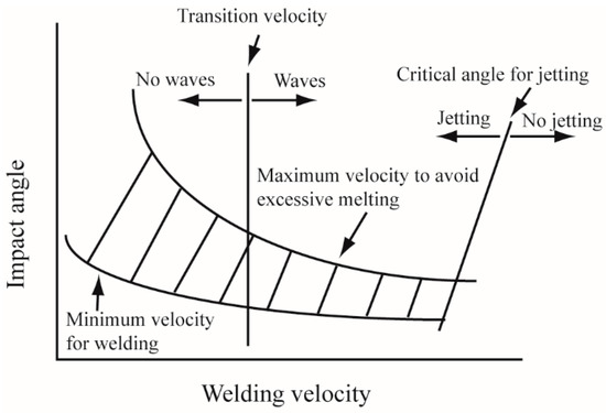
Figure 7.
Weldability window. Velocity of welding (Vw) is represented by V1 in Figure 5c. The dynamic angle of obliquity is the impact angle. When the combination of parameters is within the welding range, welding will take place.
4.2. Effect of Welding Parameters on Weld Quality
The welding parameters that have been investigated in different papers vary; for example, they have included the impact angle, detonation velocity, impact velocity, standoff distance, and discharge energy.
4.2.1. Effect of Welding Parameters on Wave Formation
In EXW, wave formation was believed to be a sign of strong metallurgical bonding between the flyer and the target. Therefore, early work on EXW focused on establishing critical parameters for wave formation. Deribas et al. studied the effect of detonation velocity, standoff distance, and initial angle on wave formation [95]. They pointed out that with a high detonation velocity, there was a critical angle below which there was no wave. With a low detonation velocity, there was no critical angle, but the wave dimension (amplitude and wavelength) would increase with the initial angle and standoff distance. Furthermore, for each fixed initial angle, there was a critical impact velocity for wave formation, and the impact velocity increased with the initial angle. However, they couldn’t establish the direct relationship between the wave dimension and the initial angle, impact velocity, and standoff distance, since in each serial experiment, there were more than two parameters varying at the same time. Their conclusion was consistent with the jet formation regimes in which there was a critical initial angle that was required for supersonic flow, whereas there was no requirement for subsonic flow [19].
Acarer et al. [14] studied the effect of explosive loading and standoff distance on the wave dimension. The experimental results showed that the wave dimension increased with standoff distance and explosive loading. Durgutlu et al. [96] also found a similar effect of standoff on wave dimension; they also observed that the bonding interface was straight with a lower standoff distance, while with a higher standoff, the bonding interface had a wavy feature. However, they didn’t build the quantitative relationship between the welding parameters and the wave dimension.
4.2.2. Effect of Welding Parameters on Mechanical Properties
The weld quality is usually evaluated with a tensile test and a peeling test; the weld quality is compared by measuring the fracture strength and observing the fracture location. When the fracture location is at the weld interface, the weld quality is ordered by the fracture strength. In some other cases, the fracture location is on the base metals, which indicated that the weld quality is better than the base metal strength. Several researchers investigated the effect of the parameters on the weld quality.
Kore et al. studied the welding parameters in MPW. Al with a thickness of one mm was welded with a discharge energy of 3.6 kJ. The bonding strength increased with increasing discharge energy. They also found that there was an optimum standoff distance in magnetic pulse welding, which was also concluded by Hokari et al. [39]. This observation was not applicable to EXW. In MPW, the highest impact velocity occurs at the peak primary current. Therefore, before the impact velocity gets to its highest value, the flyer travels a specific distance, which is determined by the impact velocity and the rise time of the primary current. So, a specific standoff distance is needed for a specific MPW process.
In a study of the bonding interface of explosively welded steel to steel, microhardness increased at the bonding interface, but decreased far from the bonding interface [14]. However, Gulenc [73] observed that microhardness increased both at the bonding interface and far from the bonding interface. Microhardness should increase both at the bonding interface and the outer surface of the welded samples, which is caused by work hardening. The outer surface of the flyer is work-hardened by the explosives, and the outer surface of the target is work-hardened by the interaction with anvil. The decrease of hardness far from the bonding interface may be caused by softening.
Chizari and Barrett studied impact velocity with an aluminum flyer that was two-mm thick [33]. They found that there was no bonding when the impact velocity was lower than 250 m/s, and that a wave interface began to appear when the impact velocity was 340 m/s. Besides the impact velocity, they also studied the effect of two flyers on the weld quality. In their experiment, two pieces of parallel flyers with a separate distance were used. Their experimental results showed that the weld quality between the first flyer and the target was better than that between the two flyers. They attributed the poor bond between the two flyers to the increased roughness of the back surface of the first flyer during the colliding process. However, it should be noted that during the colliding process, the roughness of the target also increased. So, roughness was not causing the poor bond between the two flyers.
To summarize the research about welding parameters, welding parameters vary in different research papers, and some of them are dependent on specific techniques, and even specific experimental setups. For example, the flyer will be applied with a different impact force despite using the same capacitor bank energy and different actuators. Therefore, the basic parameters should be studied extensively. In former studies, the impact angle and impact velocity were chosen as the factors that can determine the weld quality. However, the jet formation is much more reliant on the impact pressure and impact angle. Kinetic energy is also very critical in determining the weld quality in order to avoid melting and solidification. Therefore, welding parameters need to be carefully investigated in order to figure out which ones could be selected to build the weldability window.
In explosive welding, the fatigue life of welded joints was also studied. Karolczuk et al. investigated the fatigue phenomena of explosively welded Fe/Ti [24]. They studied two types of bonding interface: flat interface and wavy interface. They concluded that a flat interface has a higher fatigue life than a wavy interface. Through the study of Szachogluchowicz et al. [27], it was found that the lower fatigue life of the wavy interface may be due to the stress concentration. In their study, heat treatment improved the fatigue life by stress relaxation and the elimination of microvoids. Prażmowski et al. [26] studied the fatigue life of explosively welded Zr/Fe, and concluded that the remelted layer in the bonding zone increased the fatigue life. This phenomena was also due to the stress relaxation. The corrosion behavior of explosively welded Al/Fe was studied by Kaya [29] with neutral salt spray (NSS) tests. Their results showed that the corrosion occurred on the steel side, while no corrosion behavior was observed on the Al side. Therefore, a cladded Al layer played a significant role in the protection of steel.
5. Conclusion and Future Work
High-velocity impact welding is suitable to join dissimilar materials and other specific materials, and has potential applications in industries. The conclusions are listed below.
- In high-velocity impact welding, the weld configuration was limited by the experimental setup. The current general welding configurations are lap joint (cladding), spot weld, and tubular weld. More welding configurations should be developed for wider applications of high-velocity impact welding.
- EXW and MPW have been applied in industries for lap weld/cladding. The current application is limited by weld configurations. The application of VFAW and LIW is under investigation.
- In EXW, jet formation theory was built based on the assumption of a fluid-like flow when the materials are under high-impact pressure. However, the minimum impact pressure that is required for the fluid-like flow at the collision point was not determined. For the further optimization of this theory, this point should be stated.
- Two types of bonding interface were observed in high-velocity impact welding based on the geometric shape of the bonding interface: a straight interface or a wave interface (with or without vortices). Generally, a straight interface has lower mechanical properties than a wave interface without vortices due to the interlocking or greater metallurgical bonding area between the flyer and the target. A wave interface with vortices is accompanied by a melting phenomenon, which resulted in the low mechanical properties. Therefore, for each material combination, there should be a transition range from a straight interface to a wave interface with vortices, which might be the strongest metallurgical bonding. The welding parameters should be optimized for each material combination for this transition range.
- Regarding the compositional change across the collision interface, there are sharp interfaces and transition layer interfaces. The sharp interface is the result of solid-state welding, while the transition layer interface may be the result of solid-state bonding or melting. The melting also resulted in intermetallics, microvoids, and amorphous materials.
- For the application of LIW in manufacturing, welding parameters need to be studied extensively in order to build the relationship between the welding parameters and weld quality systematically and avoid the spallation of the target and rebound behavior of the flyer.
- Furthermore, the current weldability window should be re-evaluated for varied welding processes and material combinations. Whether bonding happens or not is not only related to impact angle and impact velocity, but also to the hardness, thickness, and density of the flyer.
Author Contributions
Conceptualization, H.W. and Y.W.; Literature search, H.W.; Literature summarization, H.W. and Y.W.; writing—original draft preparation, H.W.; writing—review and editing, Y.W.
Funding
This research was funded by the Fundamental Research Funds for the Central Universities, grant number 06500107 and the APC was funded by 06500107.
Acknowledgments
Thanks for lab members from The Ohio State University for their valuable discussions and instructions.
Conflicts of Interest
The authors declare no conflict of interest.
References
- Crossland, B. Explosive Welding of Metals and Its Application; Oxford University Press: New York, NY, USA, 1982; pp. 10–38, 84–106. [Google Scholar]
- Debroy, T.; David, S.A. Physical processes in fusion-welding. Rev. Mod. Phys. 1995, 67, 85–112. [Google Scholar] [CrossRef]
- Li, X.; Lawson, S.; Zhou, Y.; Goodwin, F. Novel technique for laser lap welding of zinc coated sheet steels. J. Laser Appl. 2007, 19, 259–264. [Google Scholar] [CrossRef]
- Durgutlu, A.; Gulenc, B.; Findik, F. Examination of copper/stainless steel joints formed by explosive welding. Mater. Des. 2005, 26, 497–507. [Google Scholar] [CrossRef]
- Taban, E.; Gould, J.E.; Lippold, J.C. Characterization of 6061-T6 aluminum alloy to AISI 1018 steel interfaces during joining and thermo-mechanical conditioning. Mater. Sci. Eng. A Struct. Mater. Prop. Microstruct. Process. 2009, 527, 1704–1708. [Google Scholar] [CrossRef]
- Sun, Z.; Ion, J.C. Laser-welding of dissimilar metal combinations. J. Mater. Sci. 1995, 30, 4205–4214. [Google Scholar] [CrossRef]
- Torkamany, M.J.; Tahamtan, S.; Sabbaghzadeh, J. Dissimilar welding of carbon steel to 5754 aluminum alloy by Nd:YAG pulsed laser. Mater. Des. 2009, 31, 458–465. [Google Scholar] [CrossRef]
- Yan, Y.B.; Zhang, Z.W.; Shen, W.; Wang, J.H.; Zhang, L.K.; Chin, B.A. Microstructure and properties of magnesium AZ31B-aluminum 7075 explosively welded composite plate. Mater. Sci. Eng. A Struct. Mater. Prop. Microstruct. Process. 2009, 527, 2241–2245. [Google Scholar] [CrossRef]
- Fuller, C.B.; Mahoney, M.W.; Calabrese, M.; Micona, L. Evolution of microstructure and mechanical properties in naturally aged 7050 and 7075 Al friction stir welds. Mater. Sci. Eng. A Struct. Mater. Prop. Microstruct. Process. 2009, 527, 2233–2240. [Google Scholar] [CrossRef]
- Atasoy, E.; Kahraman, N. Diffusion bonding of commercially pure titanium to low carbon steel using a silver interlayer. Mater. Charact. 2008, 59, 1481–1490. [Google Scholar] [CrossRef]
- Liu, J.; Watanabe, I.; Yoshida, K.; Atsuta, M. Joint strength of laser-welded titanium. Dent. Mater. 2002, 18, 143–148. [Google Scholar] [CrossRef]
- Qi, Y.L.; Deng, J.; Hong, Q.; Zeng, L.Y. Electron beam welding, laser beam welding and gas tungsten arc welding of titanium sheet. Mater. Sci. Eng. A Struct. Mater. Prop. Microstruct. Process. 2000, 280, 177–181. [Google Scholar]
- Strand, O.T.; Goosman, D.R.; Martinez, C.; Whitworth, T.L.; Kuhlow, W.W. Compact system for high-speed velocimetry using heterodyne techniques. Rev. Sci. Instrum. 2006, 77, 083108. [Google Scholar] [CrossRef]
- Acarer, M.; Gulenc, B.; Findik, F. Investigation of explosive welding parameters and their effects on microhardness and shear strength. Mater. Des. 2003, 24, 659–664. [Google Scholar] [CrossRef]
- Mendes, R.; Ribeiro, J.B.; Loureiro, A. Effect of explosive characteristics on the explosive welding of stainless steel to carbon steel in cylindrical configuration. Mater. Des. 2013, 51, 182–192. [Google Scholar] [CrossRef]
- Vivek, A.; Hansen, S.R.; Liu, B.C.; Daehn, G.S. Vaporizing foil actuator: A tool for collision welding. J. Mater. Process. Technol. 2013, 213, 2304–2311. [Google Scholar] [CrossRef]
- Wang, H.M.; Taber, G.; Liu, D.J.; Hansen, S.; Chowdhury, E.; Terry, S.; Lippold, J.C.; Daehn, G.S. Laser impact welding: Design of apparatus and parametric optimization. J. Manuf. Process. 2015, 19, 118–124. [Google Scholar] [CrossRef]
- Zhang, Y.; Babu, S.S.; Prothe, C.; Blakely, M.; Kwasegroch, J.; LaHa, M.; Daehn, G.S. Application of high velocity impact welding at varied different length scales. J. Mater. Process. Technol. 2011, 211, 944–952. [Google Scholar] [CrossRef]
- Bahrani, A.S.; Black, T.J.; Crosslan, B. Mechanics of wave formation in explosive welding. Proc. R. Soc. Lond. Ser. A Math. Phys. Sci. 1967, 296, 123–136. [Google Scholar]
- Young, G. Explosive welding, technical growth and commercial history. In Proceedings of the Stainless Steel World 2004, Houston, TX, USA, 20–22 October 2004; pp. 1–2. [Google Scholar]
- Philipchuk, V.; Scituate, N.; Roy, L.F. Explosive Welding. U.S. patent 3,024,526, 13 March 1962. [Google Scholar]
- Carpenter, S.H.; Wittman, R.H. Explosion welding. Annu. Rev. Mater. Sci. 1975, 5, 177–199. [Google Scholar] [CrossRef]
- Rozumek, D.; Bański, R. Crack growth rate under cyclic bending in the explosively welded steel/titanium bimetals. Mater. Des. 2012, 38, 139–146. [Google Scholar] [CrossRef]
- Karolczuk, A.; Kowalski, M.; Bański, R.; Żok, F. Fatigue phenomena in explosively welded steel–titanium clad components subjected to push–pull loading. Int. J. Fatigue 2013, 48, 101–108. [Google Scholar] [CrossRef]
- Xie, M.-X.; Shang, X.-T.; Zhang, L.-J.; Bai, Q.-L.; Xu, T.-T. Interface Characteristic of Explosive-Welded and Hot-Rolled TA1/X65 Bimetallic Plate. Metals 2018, 8, 159. [Google Scholar] [CrossRef]
- Prażmowski, M.; Rozumek, D.; Paul, H. Static and fatigue tests of bimetal Zr-steel made by explosive welding. Eng. Fail. Anal. 2017, 75, 71–81. [Google Scholar] [CrossRef]
- Szachogluchowicz, I.; Sniezek, L.; Hutsaylyuk, V. Low cycle fatigue properties of AA2519–Ti6Al4V laminate bonded by explosion welding. Eng. Fail. Anal. 2016, 69, 77–87. [Google Scholar] [CrossRef]
- Topolski, K.; Szulc, Z.; Garbacz, H. Microstructure and Properties of the Ti6Al4V/Inconel 625 Bimetal Obtained by Explosive Joining. J. Mater. Eng. Perform. 2016, 25, 3231–3237. [Google Scholar] [CrossRef]
- Kaya, Y. Microstructural, Mechanical and Corrosion Investigations of Ship Steel-Aluminum Bimetal Composites Produced by Explosive Welding. Metals 2018, 8, 544. [Google Scholar] [CrossRef]
- Findik, F. Recent developments in explosive welding. Mater. Des. 2011, 32, 1081–1093. [Google Scholar] [CrossRef]
- Carvalho, G.H.S.F.L.; Galvão, I.; Mendes, R.; Leal, R.M.; Loureiro, A. Influence of base material properties on copper and aluminium–copper explosive welds. Sci. Technol. Weld. Join. 2018, 23, 501–507. [Google Scholar] [CrossRef]
- Botros, K.K.; Groves, T.K. Fundamental impact-welding parameters—An experimental investigation using a 76-Mm powder cannon. J. Appl. Phys. 1980, 51, 3706–3714. [Google Scholar] [CrossRef]
- Chizari, M.; Barrett, L.M. Single and double plate impact welding: Experimental and numerical simulation. Comput. Mater. Sci. 2009, 46, 828–833. [Google Scholar] [CrossRef]
- Mousavi, A.A.A.; Al-Hassani, S.T.S. Numerical and experimental studies of the mechanism of the wavy interface formations in explosive/impact welding. J. Mech. Phys. Solids 2005, 53, 2501–2528. [Google Scholar] [CrossRef]
- Katzenstein, J. System and Method for Impact Welding by Magnetic Propulsion. U.S. patent 4,504,714, 12 March 1985. [Google Scholar]
- Lee, K.J.; Kumai, S.; Arai, T.; Aizawa, T. Interfacial microstructure and strength of steel/aluminum alloy lap joint fabricated by magnetic pressure seam welding. Mater. Sci. Eng. A Struct. Mater. Prop. Microstruct. Process. 2007, 471, 95–101. [Google Scholar] [CrossRef]
- Kochan, A. Magnetic pulse welding shows potential for automotive applications. Assem. Autom. 2000, 20, 129–131. [Google Scholar] [CrossRef]
- Kore, S.; Date, P.; Kulkarni, S.; Kumar, S.; Rani, D.; Kulkarni, M.; Desai, S.; Rajawat, R.; Nagesh, K.; Chakravarty, D. Electromagnetic impact welding of copper-to-copper sheets. Int. J. Mater. Form. 2009, 3, 117–121. [Google Scholar] [CrossRef]
- Hokari, H.; Sato, T.; Kawauchi, K.; Muto, A. Magnetic impulse welding of aluminium tube and copper tube with various core materials. Weld. Int. 1998, 12, 619–626. [Google Scholar] [CrossRef]
- Marya, M.; Marya, S. Interfacial microstructures and temperatures in aluminium-copper electromagnetic pulse welds. Sci. Technol. Weld. Join. 2004, 9, 541–547. [Google Scholar] [CrossRef]
- Patra, S.; Arora, K.S.; Shome, M.; Bysakh, S. Interface characteristics and performance of magnetic pulse welded copper-Steel tubes. J. Mater. Process. Technol. 2017, 245, 278–286. [Google Scholar] [CrossRef]
- Kore, S.D.; Imbert, J.; Worswick, M.J.; Zhou, Y. Electromagnetic impact welding of Mg to Al sheets. Sci. Technol. Weld. Join. 2009, 14, 549–553. [Google Scholar] [CrossRef]
- Ben-Artzy, A.; Stern, A.; Frage, N.; Shribman, V. Interface phenomena in aluminium-magnesium magnetic pulse welding. Sci. Technol. Weld. Join. 2008, 13, 402–408. [Google Scholar] [CrossRef]
- Jiang, X.; Chen, S. Texture evolution and plastic deformation mechanism in magnetic pulse welding of dissimilar Al and Mg alloys. Weld. World 2018, 62, 1159–1171. [Google Scholar] [CrossRef]
- Aizawa, T.; Kashani, M.; Okagawa, K. Application of magnetic pulse welding for aluminum alloys and SPCC steel sheet joints. Weld. J. 2007, 86, 119S–124S. [Google Scholar]
- Geng, H.; Mao, J.; Zhang, X.; Li, G.; Cui, J. Strain rate sensitivity of Al-Fe magnetic pulse welds. J. Mater. Process. Technol. 2018, 262, 1–10. [Google Scholar] [CrossRef]
- Deng, F.; Cao, Q.; Han, X.; Li, L. Electromagnetic pulse spot welding of aluminum to stainless steel sheets with a field shaper. Int. J. Adv. Manuf. Technol. 2018, 98, 1903–1911. [Google Scholar] [CrossRef]
- Cui, J.; Sun, T.; Geng, H.; Yuan, W.; Li, G.; Zhang, X. Effect of surface treatment on the mechanical properties and microstructures of Al-Fe single-lap joint by magnetic pulse welding. Int. J. Adv. Manuf. Technol. 2018, 98, 1081–1092. [Google Scholar] [CrossRef]
- Watanabe, M.; Kumai, S.; Hagimoto, G.; Zhang, Q.; Nakayama, K. Interfacial microstructure of aluminum/metallic glass lap joints fabricated by magnetic pulse welding. Mater. Trans. 2009, 50, 1279–1285. [Google Scholar] [CrossRef]
- Cui, J.; Li, Y.; Liu, Q.; Zhang, X.; Xu, Z.; Li, G. Joining of tubular carbon fiber-reinforced plastic/aluminum by magnetic pulse welding. J. Mater. Process. Technol. 2019, 264, 273–282. [Google Scholar] [CrossRef]
- Kamal, M.; Daehn, G.S. A uniform pressure electromagnetic actuator for forming flat sheets. J. Manuf. Sci. Eng. Trans. ASME 2007, 129, 369–379. [Google Scholar] [CrossRef]
- Kore, S.D.; Date, P.P.; Kulkarni, S.V. Electromagnetic impact welding of aluminum to stainless steel sheets. J. Mater. Process. Technol. 2008, 208, 486–493. [Google Scholar] [CrossRef]
- Kore, S.D.; Date, P.P.; Kulkarni, S.V.; Kumar, S.; Kulkarni, M.R.; Desai, S.V.; Rajawat, R.K.; Nagesh, K.V.; Chakravarty, D.P. Electromagnetic impact welding of Al-to-Al-Li sheets. J. Manuf. Sci. Eng. Trans. ASME 2009, 131, 1–4. [Google Scholar] [CrossRef]
- Zhang, Y.; Babu, S.; Daehn, G.S. Impact welding in a variety of geometric configurations. In Proceedings of the 4th International Conference on High Speed Forming, Columbus, OH, USA, 9–10 March 2010; pp. 97–107. [Google Scholar]
- Daehn, G.S.; Lippold, J.C. Low Temperature Spot Impact Welding Driven without Contact. U.S. patent 8084710B2, 27 December 2011. [Google Scholar]
- Wang, H.; Vivek, A.; Wang, Y.; Taber, G.; Daehn, G.S. Laser impact welding application in joining aluminum to titanium. J. Laser Appl. 2016, 28, 032002. [Google Scholar] [CrossRef]
- Liu, H.; Gao, S.; Yan, Z.; Li, L.; Li, C.; Sun, X.; Sha, C.; Shen, Z.; Ma, Y.; Wang, X. Investigation on a Novel Laser Impact Spot Welding. Metals 2016, 6, 179. [Google Scholar] [CrossRef]
- Wang, H.; Wang, Y. Laser-driven flyer application in thin film dissimilar materials welding and spalling. Opt. Lasers Eng. 2017, 97, 1–8. [Google Scholar] [CrossRef]
- Wang, X.; Shao, M.; Gao, S.; Gau, J.-T.; Tang, H.; Jin, H.; Liu, H. Numerical simulation of laser impact spot welding. J. Manuf. Process. 2018, 35, 396–406. [Google Scholar] [CrossRef]
- Vivek, A. Rapid Vaporization of Thin Conductors Used for Impulse Metalworking. Ph.D. Thesis, The Ohio State University, Columbus, OH, USA, 2012. [Google Scholar]
- Chen, S.; Huo, X.; Guo, C.; Wei, X.; Huang, J.; Yang, J.; Lin, S. Interfacial characteristics of Ti/Al joint by vaporizing foil actuator welding. J. Mater. Process. Technol. 2019, 263, 73–81. [Google Scholar] [CrossRef]
- Lee, T.; Zhang, S.; Vivek, A.; Kinsey, B.; Daehn, G. Flyer thickness effect in the impact welding of aluminum to steel. J. Manuf. Sci. Eng. 2018, 140, 121002. [Google Scholar] [CrossRef]
- Liu, B.; Vivek, A.; Daehn, G.S. Joining sheet aluminum AA6061-T4 to cast magnesium AM60B by vaporizing foil actuator welding: Input energy, interface, and strength. J. Manuf. Process. 2017, 30, 75–82. [Google Scholar] [CrossRef]
- Chen, S.; Daehn, G.S.; Vivek, A.; Liu, B.; Hansen, S.R.; Huang, J.; Lin, S. Interfacial microstructures and mechanical property of vaporizing foil actuator welding of aluminum alloy to steel. Mater. Sci. Eng. A 2016, 659, 12–21. [Google Scholar] [CrossRef]
- Vivek, A.; Presley, M.; Flores, K.M.; Hutchinson, N.H.; Daehn, G.S. Solid state impact welding of BMG and copper by vaporizing foil actuator welding. Mater. Sci. Eng. A 2015, 634, 14–19. [Google Scholar] [CrossRef]
- Hahn, M.; Weddeling, C.; Taber, G.; Vivek, A.; Daehn, G.S.; Tekkaya, A.E. Vaporizing foil actuator welding as a competing technology to magnetic pulse welding. J. Mater. Process. Technol. 2016, 230, 8–20. [Google Scholar] [CrossRef]
- Gupta, V.; Lee, T.; Vivek, A.; Choi, K.S.; Mao, Y.; Sun, X.; Daehn, G. A robust process-structure model for predicting the joint interface structure in impact welding. J. Mater. Process. Technol. 2019, 264, 107–118. [Google Scholar] [CrossRef]
- Birkhoff, G.; Macdougall, P.D.; Pugh, M.E.; Taylor, G. Explosives with lined cavities. J. Appl. Phys. 1948, 19, 563–582. [Google Scholar] [CrossRef]
- Cowan, R.G.; Holtzman, H.A. Flow configurations in colliding plates-explosive bonding. J. Appl. Phys. 1963, 34, 928–939. [Google Scholar] [CrossRef]
- Bahrani, A.S.; Crossland, B. Explosive welding and cladding: An introductory survey and preliminary results. Proc. Inst. Mech. Eng. 1964, 179, 264–304. [Google Scholar] [CrossRef]
- Szecket, A.; Inal, O.T.; Vigueras, D.J.; Rocco, J. A wavy versus straight interface in the explosive welding of aluminum to steel. J. Vac. Sci. Technol. A 1985, 3, 2588–2594. [Google Scholar] [CrossRef]
- Jaramillo, V.D.; Szecket, A.; Inal, O.T. On the transition from a waveless to a wave interface in explosive welding. Mater. Sci. Eng. 1987, 91, 217–222. [Google Scholar] [CrossRef]
- Gulenc, B. Investigation of interface properties and weldability of aluminum and copper plates by explosive welding method. Mater. Des. 2008, 29, 275–278. [Google Scholar] [CrossRef]
- Acarer, M.; Demir, B. An investigation of mechanical and metallurgical properties of explosive welded aluminum-dual phase steel. Mater. Lett. 2008, 62, 4158–4160. [Google Scholar] [CrossRef]
- Kaçar, R.; Acarer, M. Microstructure-property relationship in explosively welded duplex stainless steel-steel. Mater. Sci. Eng. A 2003, 363, 290–296. [Google Scholar] [CrossRef]
- Kahraman, N.; Gulenc, B.; Findik, F. Joining of titanium/stainless steel by explosive welding and effect on interface. J. Mater. Process. Technol. 2005, 169, 127–133. [Google Scholar] [CrossRef]
- Mousavi, S.; Sartangi, P.F. Experimental investigation of explosive welding of cp-titanium/AISI 304 stainless steel. Mater. Des. 2009, 30, 459–468. [Google Scholar] [CrossRef]
- Kahraman, N.; Gulenc, B. Microstructural and mechanical properties of Cu-Ti plates bonded through explosive welding process. J. Mater. Process. Technol. 2005, 169, 67–71. [Google Scholar] [CrossRef]
- Mousavi, S.; Al-Hassani, S.T.S.; Atkins, A.G. Bond strength of explosively welded specimens. Mater. Des. 2008, 29, 1334–1352. [Google Scholar] [CrossRef]
- Nassiri, A.; Chini, G.; Vivek, A.; Daehn, G.; Kinsey, B. Arbitrary Lagrangian–Eulerian finite element simulation and experimental investigation of wavy interfacial morphology during high velocity impact welding. Mater. Des. 2015, 88, 345–358. [Google Scholar] [CrossRef]
- Loureiro, A.; Mendes, R.; Ribeiro, J.B.; Leal, R.M.; Galvão, I. Effect of explosive mixture on quality of explosive welds of copper to aluminium. Mater. Des. 2016, 95, 256–267. [Google Scholar] [CrossRef]
- Inal, O.T.; Szecket, A.; Vigueras, D.J.; Pak, H.R. Explosive welding of Ti-6al-4v to mild-steel substrates. J. Vac. Sci. Technol. A Vac. Surf. Films 1985, 3, 2605–2609. [Google Scholar] [CrossRef]
- Zhang, Y.; Babu, S.S.; Zhang, P.; Kenik, E.A.; Daehn, G.S. Microstructure characterisation of magnetic pulse welded AA6061-T6 by electron backscattered diffraction. Sci. Technol. Weld. Join. 2008, 13, 467–471. [Google Scholar] [CrossRef]
- Liu, K.X.; Liu, W.D.; Wang, J.T.; Yan, H.H.; Li, X.J.; Huang, Y.J.; Wei, X.S.; Shen, J. Atomic-scale bonding of bulk metallic glass to crystalline aluminum. Appl. Phys. Lett. 2008, 93, 1–3. [Google Scholar] [CrossRef]
- Göbel, G.; Kaspar, J.; Herrmannsdörfer, T.; Brenner, B.; Beyer, E. Insights into intermetallic phases on pulse welded dissimilar metal joints. In Proceedings of the 4th International Conference on High Speed Forming, Columbus, OH, USA, 9–10 March 2010; pp. 127–136. [Google Scholar]
- Stern, A.; Aizenshtein, M. Bonding zone formation in magnetic pulse welds. Sci. Technol. Weld. Join. 2002, 7, 339–342. [Google Scholar] [CrossRef]
- Nishida, M.; Chiba, A.; Honda, Y.; Hirazumi, J.; Horikiri, K. Electron-microscopy studies of bonding interface in explosively welded Ti/Steel clads. Isij Int. 1995, 35, 217–219. [Google Scholar] [CrossRef]
- Zhang, Y.; Babu, S.; Daehn, G. Interfacial ultrafine-grained structures on aluminum alloy 6061 joint and copper alloy 110 joint fabricated by magnetic pulse welding. J. Mater. Sci. 2010, 45, 4645–4651. [Google Scholar] [CrossRef]
- Wronka, B. Testing of explosive welding and welded joints: Joint mechanism and properties of explosive welded joints. J. Mater. Sci. 2010, 45, 4078–4083. [Google Scholar] [CrossRef]
- Grignon, F.; Benson, D.; Vecchio, K.S.; Meyers, M.A. Explosive welding of aluminum to aluminum: Analysis, computations and experiments. Int. J. Impact Eng. 2004, 30, 1333–1351. [Google Scholar] [CrossRef]
- Carvalho, G.H.S.F.L.; Galvão, I.; Mendes, R.; Leal, R.M.; Loureiro, A. Formation of intermetallic structures at the interface of steel-to-aluminium explosive welds. Mater. Charact. 2018, 142, 432–442. [Google Scholar] [CrossRef]
- Carvalho, G.H.S.F.L.; Galvão, I.; Mendes, R.; Leal, R.M.; Loureiro, A. Explosive welding of aluminium to stainless steel. J. Mater. Process. Technol. 2018, 262, 340–349. [Google Scholar] [CrossRef]
- Lueg-Althoff, J.; Bellmann, J.; Gies, S.; Schulze, S.; Tekkaya, A.E.; Beyer, E. Influence of the flyer kinetics on magnetic pulse welding of tubes. J. Mater. Process. Technol. 2018, 262, 189–203. [Google Scholar] [CrossRef]
- Carvalho, G.H.S.F.L.; Mendes, R.; Leal, R.M.; Galvão, I.; Loureiro, A. Effect of the flyer material on the interface phenomena in aluminium and copper explosive welds. Mater. Des. 2017, 122, 172–183. [Google Scholar] [CrossRef]
- Deribas, A.A.; Kudinov, V.M.; Matveenk, F.I. Effect of initial parameters on process of wave formation in explosive welding. Combust. Expl. Shock Waves 1967, 3, 344–348. [Google Scholar] [CrossRef]
- Durgutlu, A.; Okuyucu, H.; Gulenc, B. Investigation of effect of the stand-off distance on interface characteristics of explosively welded copper and stainless steel. Mater. Des. 2008, 29, 1480–1484. [Google Scholar] [CrossRef]


© 2019 by the authors. Licensee MDPI, Basel, Switzerland. This article is an open access article distributed under the terms and conditions of the Creative Commons Attribution (CC BY) license (http://creativecommons.org/licenses/by/4.0/).