Article

Wear Behavior of CuSn Coated Piston Ring Sliding against Nodular Cast Iron Cylinder Liner under Heavy-Duty Conditions

1
Marine Engineering College, Dalian Maritime University, Dalian 116026, China
2
Key Laboratory of Ship-Machinery Maintenance & Manufacture, Dalian Maritime University, Dalian 116026, China
*
Authors to whom correspondence should be addressed.
Metals 2019, 9(2), 139; https://doi.org/10.3390/met9020139
Submission received: 13 January 2019 / Revised: 21 January 2019 / Accepted: 23 January 2019 / Published: 27 January 2019

Abstract

:
In order to investigate the friction and wear behavior between the nodular cast iron cylinder liner (Fe) and CuSn coated piston ring under heavy-duty conditions, piston rings with chromium(Cr) coating and CuSn-Cr coating were tested using the piston ring reciprocating liner test rig at the simulated working conditions of 56 MPa, 200 r/min, 190 °C. Compared with the Cr/Fe pair, the CuSn coating consumption of the CuSn-Cr/Fe pair made friction coefficient and cylinder wear loss decrease by 2.8% and 51.5%, respectively. Different size Sn patches worn from the CuSn coated piston ring were embedded into the cylinder liner surface based on the surface topography. This process was shown to reduce the surface roughness of a cylinder liner and form flatter plateau structures. Chemical elements analysis indicated that plateau structures on the cylinder liner surface matched with CuSn-Cr coated ring are helpful to promote the tribo-chemical reaction and generate the reactive products to protect the mutually contacted asperities.

1. Introduction

Piston ring and cylinder liner (PRCL) is one of the most important mating pairs in a diesel engine. Its tribological performance plays an important role in the normal operation of a diesel engine. The statistical data indicates that the frictional power consumption of the PRCL accounts for a large proportion in the mechanical loss of the diesel engine [1,2,3]. Under normal circumstances, when the sliding velocity of the piston ring decreases in the vicinity of the top dead center, combustible gas will exert a high temperature and high pressure on the PRCL interface. The lubrication state of the PRCL will convert the hydrodynamic lubrication to the boundary lubrication. Extreme pressure additives, such as zinc dialkyl dithiophosphates (ZDDP), will react with the micro-asperities to form a tribo-chemical film under the boundary lubrication [4,5,6].
When the harsh working conditions emerge, the micro-asperities on the PRCL sliding surface will present in direct contact, which rapidly consumes the boundary film under the starved lubrication. As the contact area of the micro-asperities gradually expands, the microscopic adhesion is transformed to macroscopic adhesion. When the serious adhesive wear occurs in the poorly lubricated area, it will cause cylinder liner scuffing. Therefore, with the continuous strengthening of working conditions, attention is required in regard to PRCL tribological problems, such as high friction power consumption, increased wear loss, and serious scuffing tendency.
Although surface texturing on the cylinder liner or piston ring is an effective method to improve the wear behavior [7,8,9], various coatings prepared on the piston rings are also important means to improve heavy-duty friction and wear performance [10]. The CrN coating made by the physical vapor deposition or magnetron sputtering method has shown good high temperature resistance to adhesion [11,12,13,14]. In order to improve the thermal stability, oil compatibility, and internal stress of ceramic coatings, nanocomposite coatings (like TiN, TiAlN, TiSiN and TiSiCN) were developed to minimize the frictional losses and wear of piston rings in an automotive engine [15,16]. Shen et al. compared chromium-based ceramic composite (CKS) and nickel-chromium-molybdenum (NCM) coated rings sliding against cast iron liner and demonstrated that the anti-scuffing behavior of NCM is better than that of the CKS with the failure time as a criterion [17]. Wan et al. indicated that the presence of amorphous graphite-like carbon not only combated the scuffing damage and running instability effectively for conventional chromium-based coatings, but also improved the reliability and robustness of the piston rings [18]. Based on the increasing scuffing resistance experiments, diamond-like carbon (DLC) coated piston ring can protect the cast iron liner from scuffing up to 600 N normal load [19]. Its lower friction coefficient and wear loss were attributed to the formation of a mixed tribolayer [19,20,21]. But the existence of residual stress in the preparation process of DLC coating would cause the coating to crack. If stress concentration exerted on the contact interface was too high, it would lead to the coating wear or peeling [22].
Compared with hard coatings, soft coatings have also attracted widespread attention for weakening the friction surface damage. Hamilton et al. investigated the relationship between macroscopic wear and the temperature of the MoS2 coating [23]. Meng et al. indicated that the stabilized friction coefficient of the electroless nickel coating decreased with the increasing reciprocating frequency and applied load [24]. He et al. deposited a self-lubricating Ni-P-MoS2 composite coating on a mild steel substrate by electrodeposition, and it showed less wear and oxidation than the pure Ni-P coating [25]. Recently, graphene-based coatings have presented a great prospect of application to improve the friction and wear performance of the mating pair under low and moderate loads, but the friction performance did not reach the expected performance under high loads [26,27,28].
Nano-powders of Cu and Sn alloy have been commonly used as lubricating oil additives to improve tribological properties for the advantages of low shear strength and good thermal conductivity. Kumar et al. studied the friction and wear properties of CuSn alloy powders containing molybdenum sulfide under dry friction [29]. Kato et al. indicated the self-lubrication properties of the CuSn alloy containing graphites [30]. Zhao et al. prepared nano-tin as the lubricating oil additives and presented good friction reduction performance [31]. Electric arc–sprayed CuSn coating for bearing elements showed higher wear resistance under a lubricated environment than that under a dry environment [32]. Although the CuSn alloy can improve the performance of the frictional pair, there have been few reports on the focus of the friction and wear properties of CuSn coating affected by the ZDDP additives during the running-in process.
In this paper, the CuSn coated piston ring was investigated to obtain the heavy-duty friction and wear performance at the simulated working conditions of 56 MPa, 200 r/min, 190 °C. Based on the analysis of surface topography and elemental composition of the PRCL, the compatibility of tribo-chemical action between the ZDDP and CuSn coating can be obtained. This will provide coating design guidance on the piston ring in heavy-duty diesel engines.

2. Experimental Details

2.1. Experimental Materials

Cylinder liner samples utilize QT600 nodular cast iron + honing. Its hardness is measured to be an average of 413.5 ± 10 HV 0.1. Its inner diameter is 300 mm, and its thickness is 8 mm. It was cut into 60 equal portions along the circumference. The dimensions of two piston rings both have an outer diameter of 300 mm and a thickness of 5 mm. They were cut into 30 equal portions along the circumference.
Piston ring is the top ring of the marine diesel engine. Electroplating Cr coated piston ring was the commercial product, which was provided by CYPR ASIMCO (Shuang Huan Piston Ring CO., LTD., Yizheng, China). Its micro hardness is 902 ± 36 HV 0.1. The deposition of CuSn coatings was performed on Cr coating deposited on cast iron substrates by the electrodeposition technique [33,34]. The CuSn coating on the Cr coating substrate was obtained in a solution containing CuCl2·2H2O, SnCl2·2H2O and sodium tartrate. The pH was adjusted at 5.65. The coating preparation was conducted with a magnet stirrer under the constant agitation speed of 300 rpm. Graphite and iron oxide particles with a maximum size of 10 μm were gradually added to the plating bath. The resultant sample was accordingly designated as CuSn-Cr. Its micro hardness was 154 ± 6 HV 0.1. The coating hardness, average of five indentations, was determined by Vickers indentation with a load of 100 g for 15 s at the cross-section. The structural profile, cross-section topography, and elemental contents of the CuSn-Cr coated piston ring are shown in Figure 1. The structural profile is an asymmetrical shape of the barrel surface. The outer layer is a soft CuSn coating with a thickness of about 25 μm, and the inner layer is a Cr coating with a thickness of about 240 μm. Unlike the electric arc–sprayed CuSn coating [32], the holes presented in the CuSn coating may be due to Sn atom depletion [35]. The coated substrates of the two piston rings are both nodular cast iron.
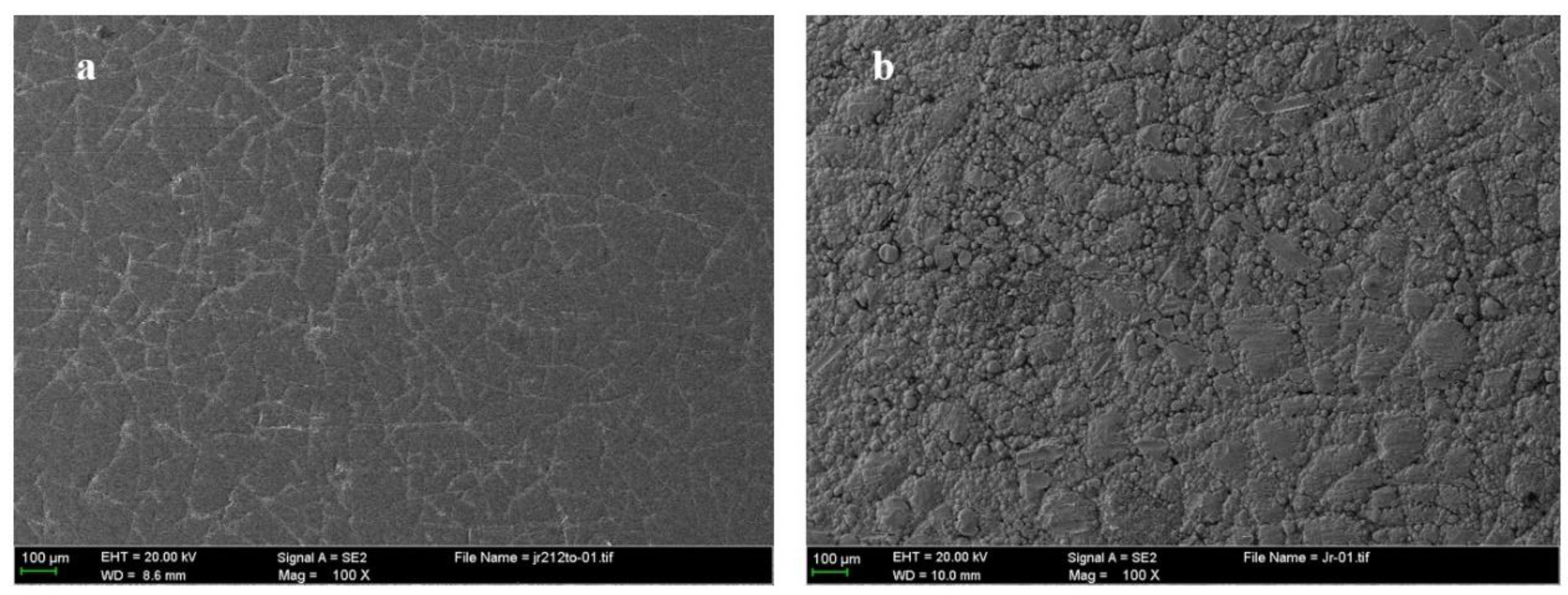
Figure 2a is the surface topography of Cr coated piston ring. The surface topography is shown to be densely covered with the electroplated mesh texture. Figure 2b presents the surface topography of CuSn-Cr coated piston ring. The surface topography is also shown to be distributed with mesh texture, and different sized Cu-Sn alloys are scattered on the surface in the form of spherical grains [36,37,38].
The lubricant was 10W-30 CD diesel oil, which was commercially available in Great Wall Lubricant Corporation of China (Beijing, China). The viscous index of this oil was 138. The viscosity was 114.9 mm2/s at 40 °C and 16.35 mm2/s at 100 °C, respectively. The extreme pressure additives were mainly ZDDP.

2.2. Experimental Procedure

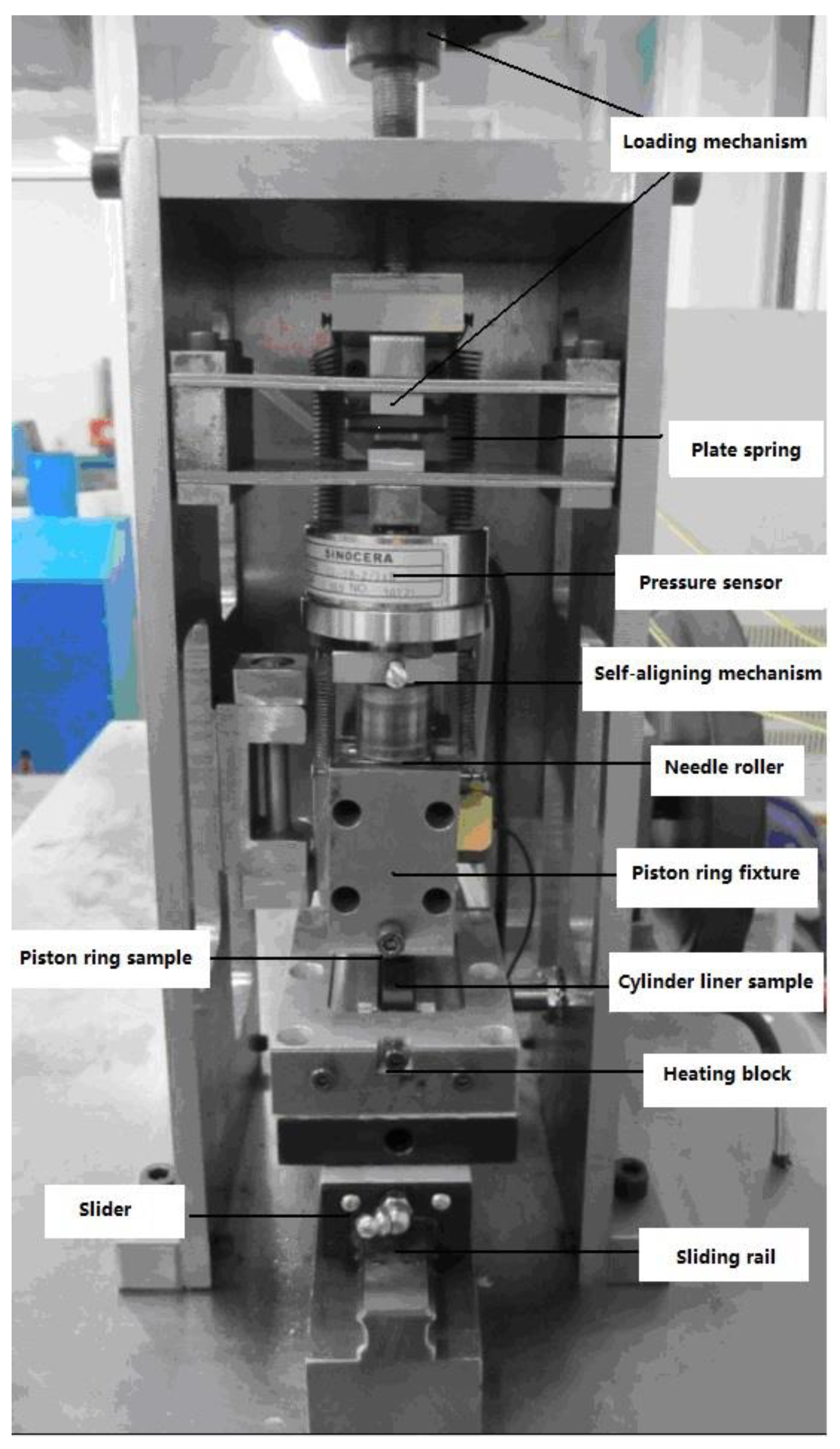
Figure 3 shows the piston ring reciprocating liner test rig [39]. The three-phase asynchronous motor rotated the crank-connecting rod mechanism through the reduction gear to reciprocate the slider. The cylinder liner sample was mounted on the heating block. In order to simulate the interface working temperature of the PRCL, the heater built in the slide block was heated with a nickel–chromium resistance wire in series and the temperature at the PRCL contact surface was measured by a e-type thermocouple. The loading mechanism through the plate spring was applied to exert the steady loading on the interface between moving parts (cylinder liner sample) and fixed parts (piston ring sample). The self-aligning mechanism and needle roller could evenly transmit the nominal pressure across the ring/liner in the circumferential direction. When the piston ring sample and cylinder liner sample had the relative sliding motion, the friction force sensor mounted behind piston ring fixture was subjected to the tension-compression action, so the friction force could be recorded online in the experiment. The test rig could accommodate a wide range of load (100 N to 10 kN), displacement frequency (1 to 40 Hz), and temperature (30 to 300 °C). The lubricating oil was supplied at the dosage of 0.1 mL/min. The oil was evenly distributed along the entire 30 mm stroke. For each test, the reciprocating frequency was set at 6.67 Hz.
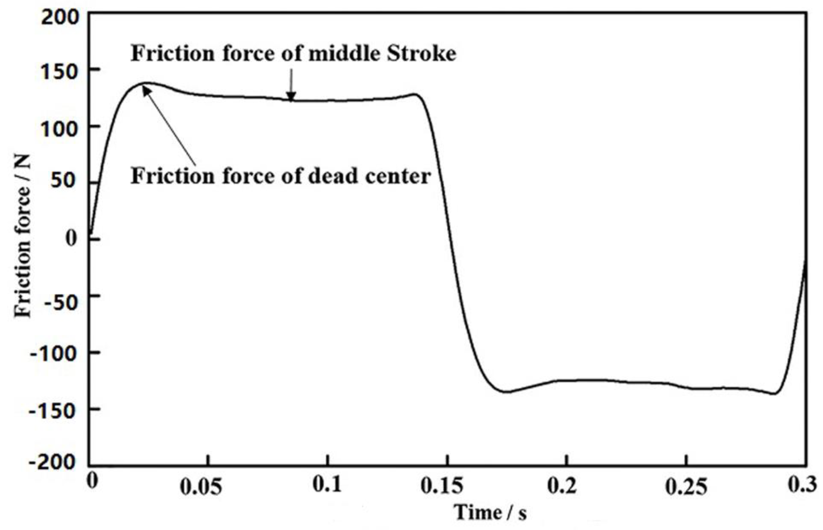
Figure 4 shows the friction force of a typical reciprocating stroke in the stable wear period. The measured friction force was filtered by the empirical mode decomposition method [40,41]. The measurement frequency is 1000 Hz. Since the dead center is the main concern, we only present the friction force variation of the CuSn-Cr and Cr coated piston rings at the dead center. One can see the comparison of the largest friction force variation at the dead center.
The experiment was divided into two stages: The running-in stage with the light load (RLL), the running-in stage with the heavy load (RHL). The RLL stage was provided to eliminate large burs and provide a stable contact state before the RHL stage. The RHL stage was to get the steady wear state.
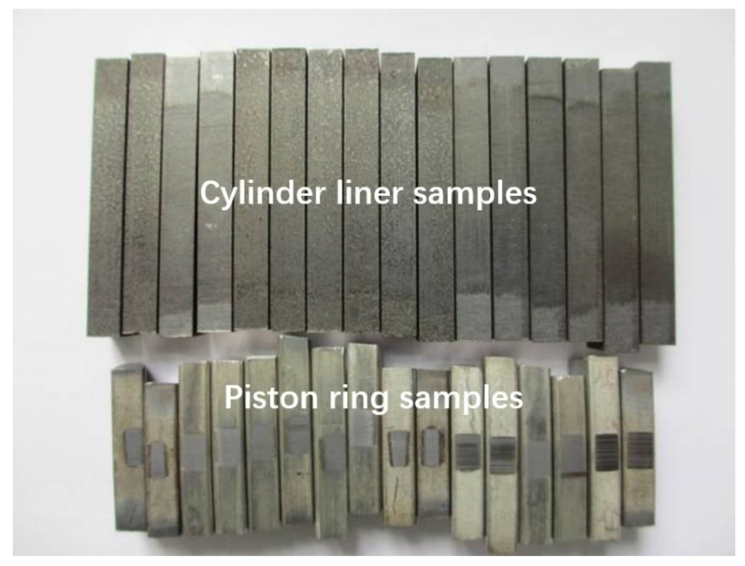
Table 1 contains the nominal pressure, temperature, and time duration of the experimental stage at the interface of the PRCL. The nominal pressure 56 MPa in the RHL stage corresponds to 1300 N. This enhanced load condition could simulate the boundary friction of PRCL at the top dead center. As the applied normal force between the PRCL is known, the friction coefficient at the dead center was calculated from the ratio of the largest friction force to normal force. The friction coefficient at the dead center and sliding time were recorded automatically during the test. The wear loss was calculated by the weight differences between the samples before and after the tests with METTLER electronic balance AL204 (Mettler-Toledo AG, Greifensee, Switzerland). Three tests were performed on each of the two piston rings under the same test conditions to check the friction coefficient and wear loss. The average and standard deviation were calculated from the three results. Figure 5 presents the typical tested PRCL samples.
In addition, the arithmetical mean deviation (Ra) of surface roughness measurements was performed before and after the running-in tests by using an OLYMPUS LEXT OLS3100 (Olympus Corporation, Tokyo, Japan). The measurement area was 256 × 256 μm2, which had a total of 1024 × 1024 sampling points. The worn and unworn surfaces were examined using a SUPRA 55 SAPPHIRE scanning electron microscope (SEM, Carl Zeiss NTS GmbH, Oberkochen, Germany) and energy dispersive X-ray spectroscopy (EDS, Carl Zeiss NTS GmbH, Oberkochen, Germany).

3. Results and Discussion

3.1. Comparision of Friction Force Variation Between the CuSn-Cr/Fe and Cr/Fe Pairs

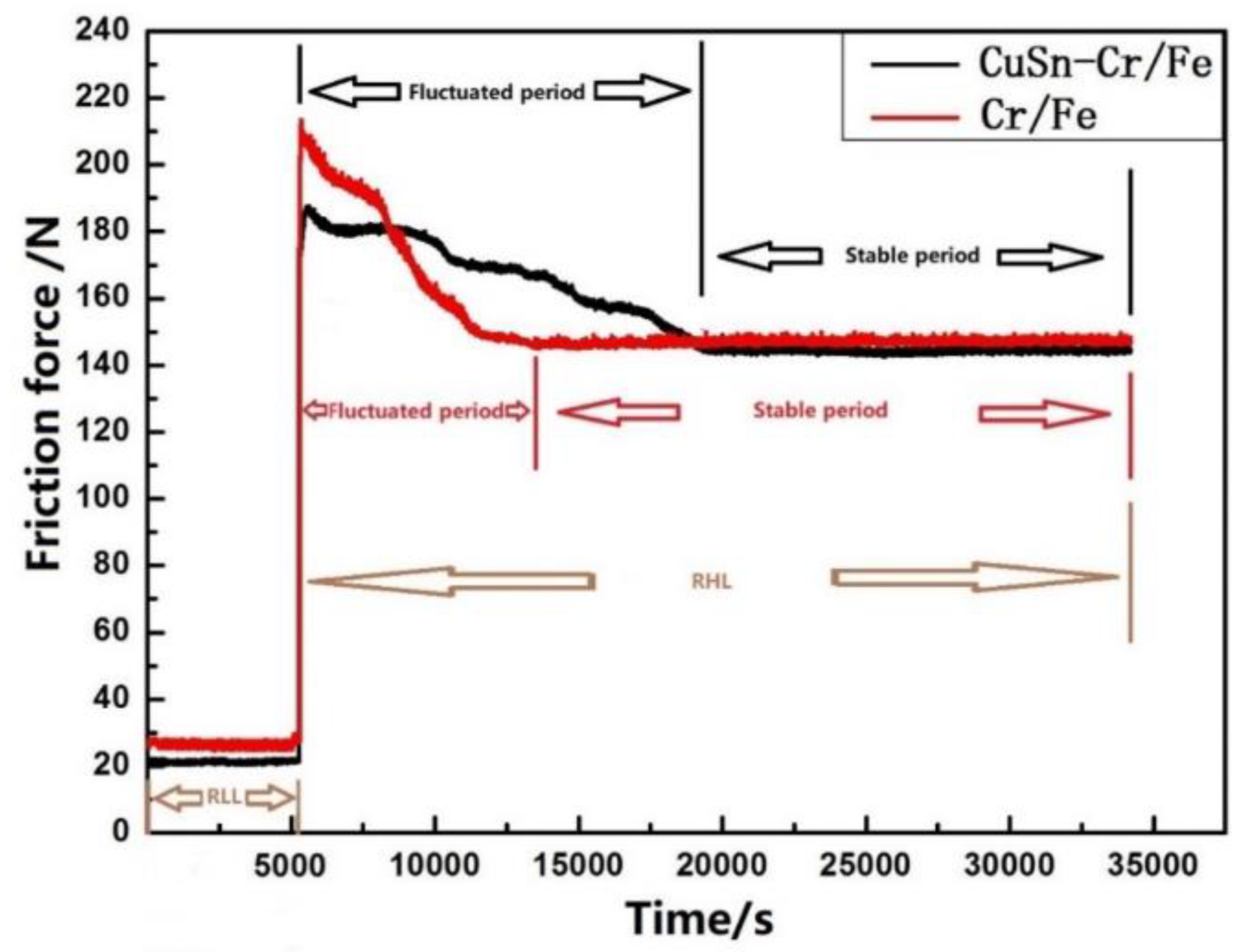
For the dead center area, the sliding velocity in the reciprocation cycle gradually decreased to zero. It was in the boundary lubrication since the fluid lubrication was difficult to form at the dead center. The tribo-chemical reaction between the asperities and ZDDP mainly generated at these areas. Meanwhile, the location of dead center areas was seriously worn. The friction force variation at dead center could reflect the wear behavior differences in the presence of CuSn coating, as shown in Figure 6.
In the RLL stage, the friction force of CuSn-Cr/Fe was lower than that of the Cr/Fe. It indicated that the CuSn coating was beginning to lubricate the dead center area. Both mating pairs show that the friction force suddenly increased and then slowly became stable as the load increased from the RLL stage to the RHL stage. Compared with the Cr/Fe pair, the friction force of CuSn-Cr/Fe pair was lower in the stable period of RHL stage. However, the time duration before entering the stable period was different, the CuSn-Cr/Fe pair was longer than the Cr/Fe pair. The Cr/Fe pair seemed more sensitive to the rapid load changes during the fluctuated period of the RHL stage, but the CuSn coating existed in the PRCL interface seemed to have a stronger ability in regard to withstanding the intensified working conditions for the CuSn-Cr/Fe pair.

3.2. Comparision of Friction Coefficient and Wear Loss between the CuSn-Cr and Cr Coated Piston Rings

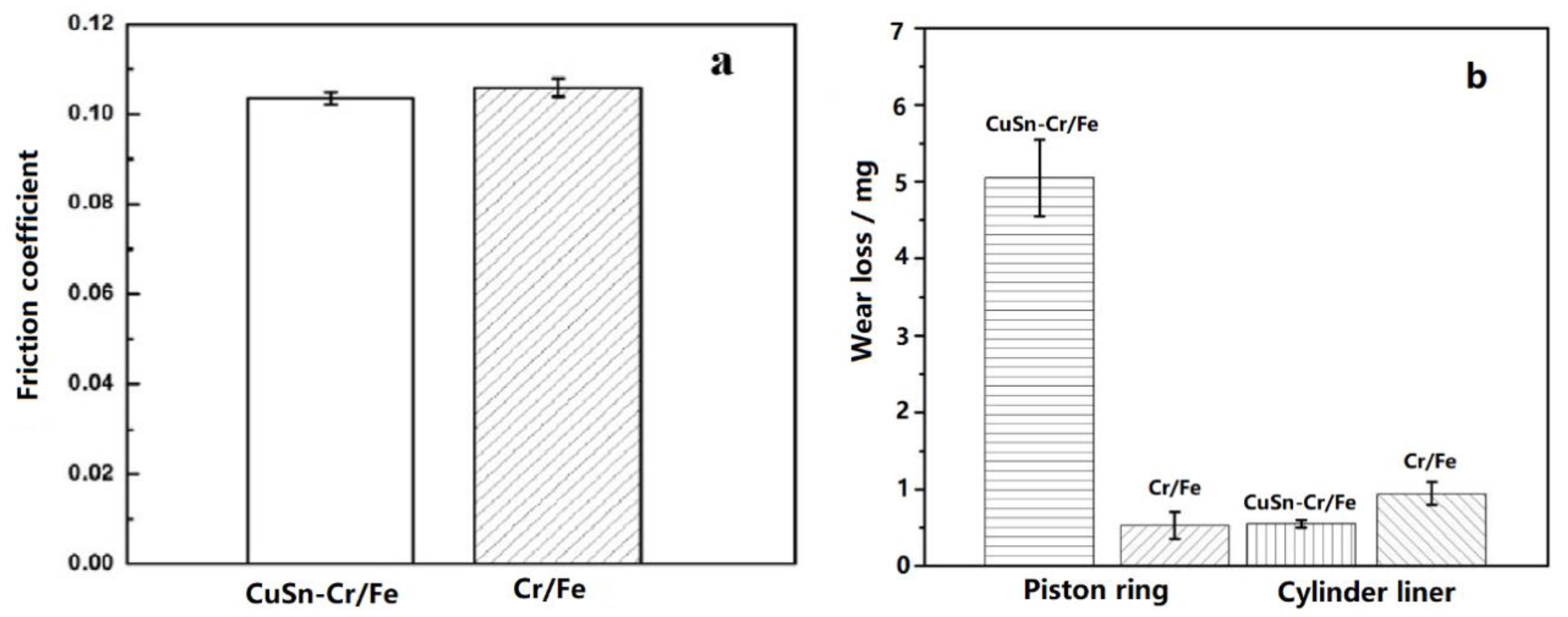
Figure 7 is the friction coefficient and wear loss of the CuSn-Cr/Fe and Cr/Fe pairs. The friction coefficient was taken from the later RHL stage. It can be seen that the friction coefficient of the Cr and CuSn-Cr coated rings was 0.106 and 0.103, respectively. The friction coefficient of the CuSn-Cr coated ring was 2.8% lower than that of the Cr coated ring, as shown in Figure 7a. The wear loss of the Cr and CuSn-Cr coated piston rings was about 0.50 mg and 5.10 mg, respectively. The wear loss of cylinder liners matched with the Cr and CuSn-Cr coated piston rings was about 0.97 mg and 0.47 mg, respectively. The cylinder wear loss of CuSn-Cr/Fe was ~51.5% lower than that of the Cr /Fe. Although wear loss of CuSn-Cr coated ring was higher than that of Cr coated ring, the wear loss of cylinder liner was restrained during the consumption of CuSn coating. The CuSn coating is helpful to improve the wear performance of nodular cast iron under oil lubrication conditions.

3.3. Surface Roughness Analysis of the CuSn-Cr/Fe and Cr/Fe Pairs

Measurements were taken before and after the running-in test to investigate the roughness changes of the PRCL as listed in Table 2. The Ra of the nodular cast iron cylinder liner was in the range of 1.05 to 1.10 µm before the running-in tests. However, upon exposure to the running-in tests, the frictional pairs both lost their roughness gradually. A decrease of the surface roughness of the CuSn-Cr/Fe after the running-in test was greater than that of the Cr/Fe.

3.4. Worn Surface Analysis of the Cylinder Liners Matched with the Cr and CuSn-Cr Coated Piston Rings

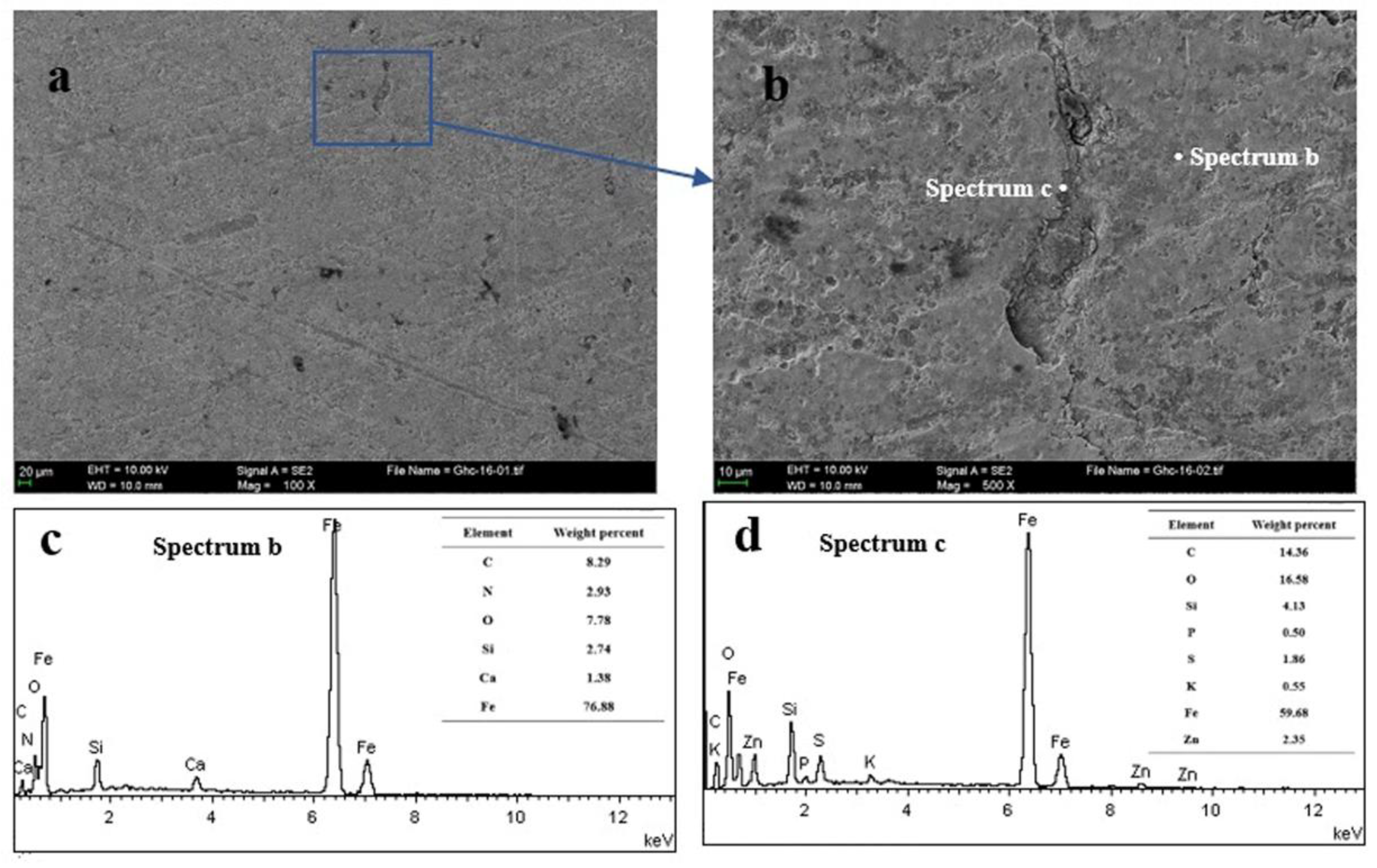
Figure 8 presents the topography and element contents of the cylinder liner matched with Cr coated piston ring. Adhesive wear can be seen on the surface topography. The honing textures were crushed and fractured to form worn debris. Some of the worn debris accumulated at the groove. It was found that the position b did not contain the elements from the lubricating oil extreme pressure additive, but position c contained S, P, Zn of extreme pressure additives agglomerated at the surface groove periphery.
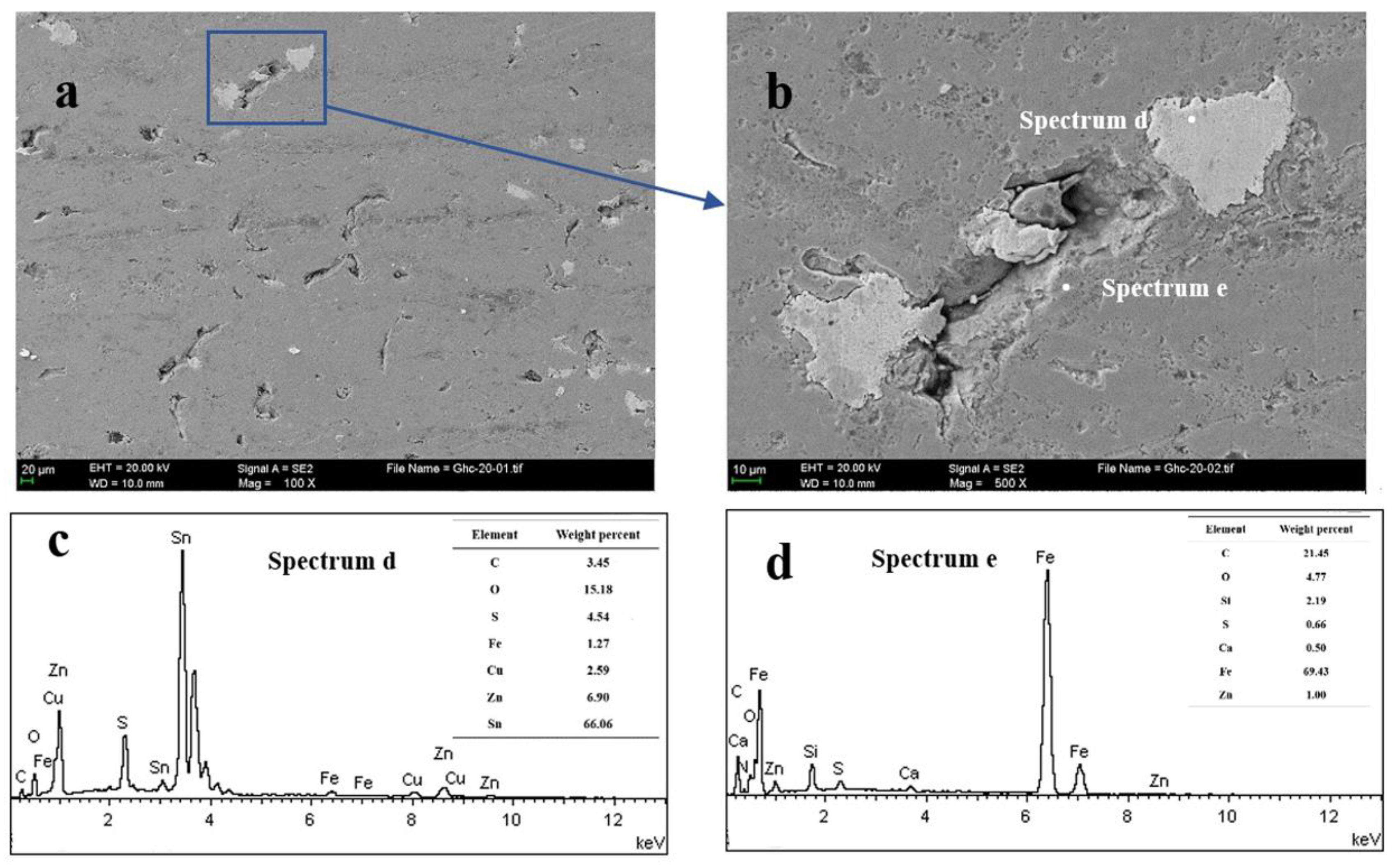
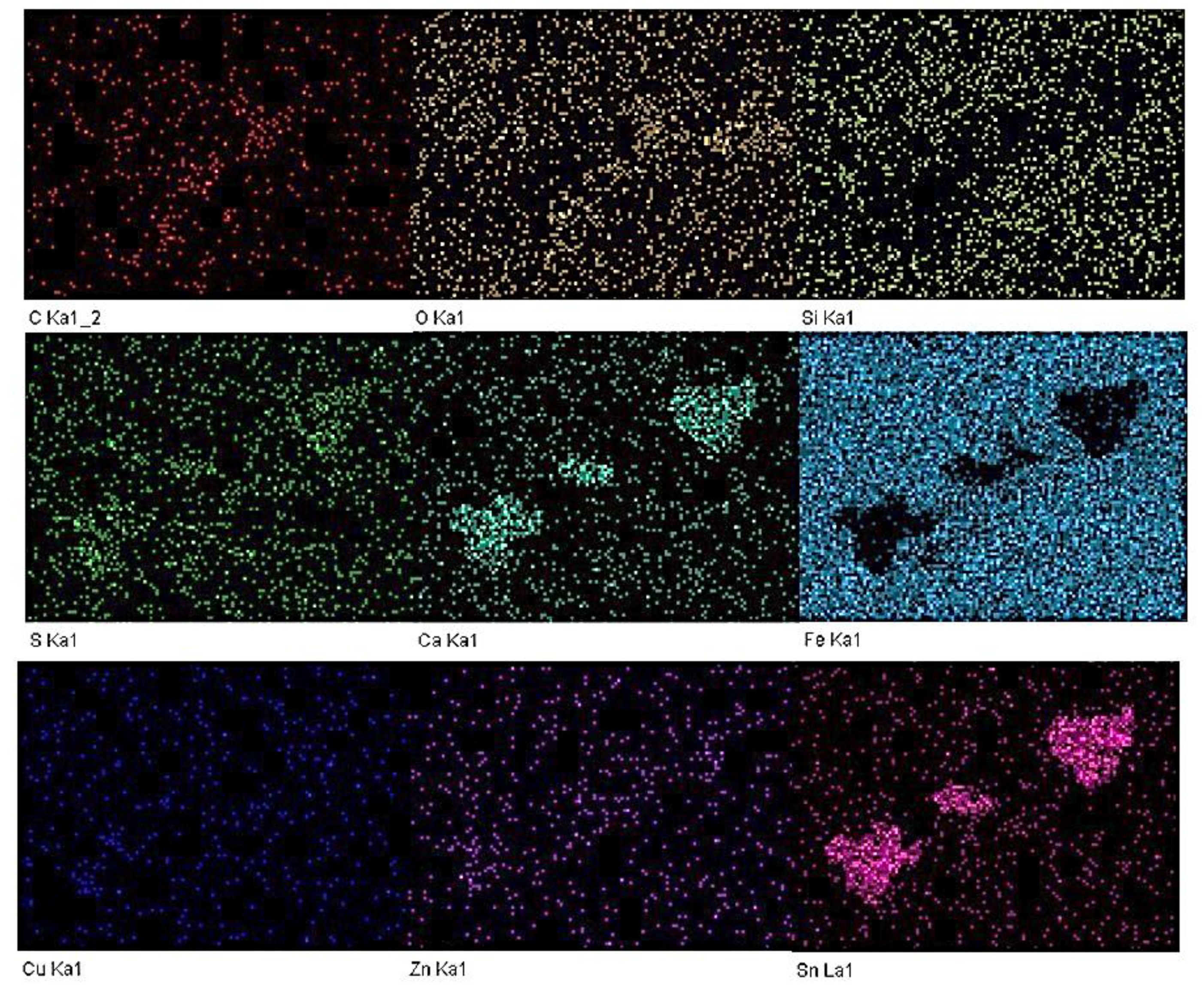
Figure 9 presents the topography and element contents of the cylinder liner matched with CuSn-Cr coated piston ring. The surface groove of the cylinder liner was obviously covered with different size patches. Elements Cu, Sn, S, Zn were found in position d. The main element was Sn. Elements S, Zn were also found at the surface groove periphery (such as position e) away from the Sn patches. Figure 10 presents the elemental distribution mapping of the Figure 9b. The elemental composition of the patches was mainly element Sn worn from the CuSn coated piston ring, as well as element S, Ca, Zn from the lubricating oil additives gathered on the patches. Element Cu presented a scattered distribution, unlike element the Sn concentration found in the grooves. The reason may be attributed to the following causes: (a) The content of Sn in CuSn coating is higher than that of Cu; (b) tin melts more easily than copper under the frictional heat action, forming a flow of metallic tin that fills the grooves under the reciprocating friction.
During the sliding friction of the mating pair, the surface of the CuSn coated ring was scratched into different size Sn particles to fill the worn pits. Element S, Zn from ZDDP additives were attached with more tribo-chemical reaction products on the Sn patches. These tribo-chemical products were generated from the chemical decomposition of the extreme pressure additive as well as the tribo-chemical reaction between the extreme pressure additives and the surface asperities. It was mainly caused by the increased stress concentration in the contact region or an instantaneous increased temperature. The resulting products generated a boundary protective film on the contact surface just like the solid lubricant, improving the wear behavior of the CuSn-Cr/Fe pair.

3.5. Worn Surface Analysis of the Cr and CuSn-Cr Coated Piston Rings

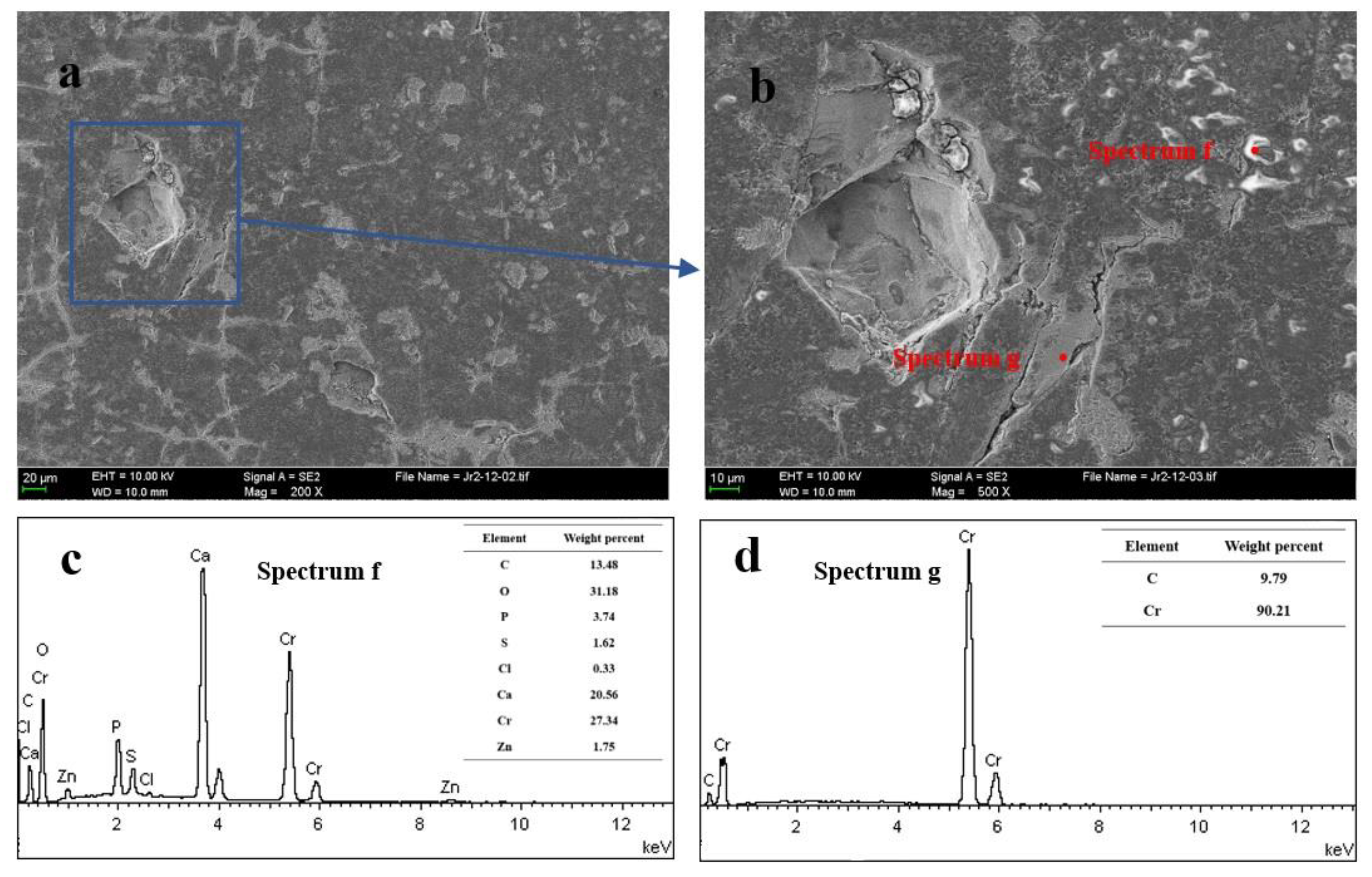
Figure 11 presents the topography and element contents of the Cr coated piston ring. It can be seen that severe fatigue spalling emerged on the piston ring, as shown in Figure 11a. Although Cr particles had peeled off from the piston ring, we found no evidence of contamination of the cylinder liner. This indicates that the frictional pair in the running-in process had not undergone adhesive wear under oil lubrication conditions. The surface of piston ring was also unevenly distributed with white sediment, as shown in Figure 11b. Position f shows that these sediments contained P, S, Zn elements from the EP (extreme pressure) additives, but position g presented none of the extreme pressure additives. This may be due to the ZDDP additives deposited in the grooves and micro-cracks, while no deposits were found on the plateaus [42].
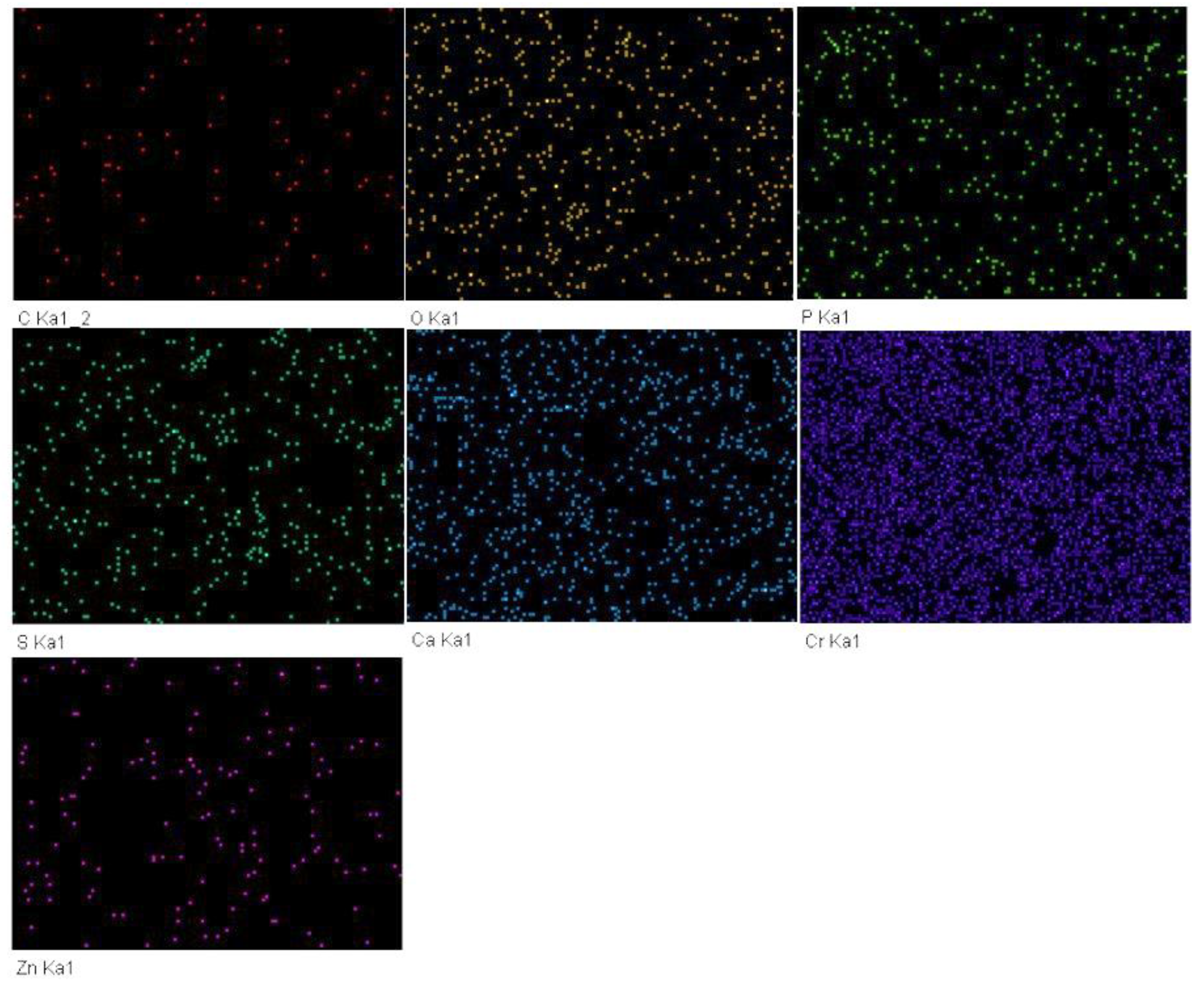
Figure 12 presents the topography and element contents of the CuSn-Cr coated piston ring. Compared with the topography of the Cr coated piston ring, the topography of CuSn-Cr coated piston ring presented local mild spalling. Based on the EDS analysis of position g and position h, none of the Cu and Sn elements existed on the surface of CuSn-Cr coated piston ring. The elemental distribution mapping of Figure 12b also indicates that the CuSn coating had been almost consumed, as shown in Figure 13. It indicates that the coating had worn away from the piston ring surface in the later worn stage, but S, P, Zn elements existed and were evenly distributed on the piston ring. This indicates that the CuSn coating consumption process can contribute to the tribo-chemical reaction on the PRCL interface. The further demonstrates the possibility that the CuSn coating existing on the piston ring is helpful to improve the friction and wear behavior of the PRCL.

3.6. Wear Mechanism Discussion of the CuSn Coating

For the cylinder liner matched with Cr coated ring, the micro-asperities on the cylinder liner surface are gradually plastically deformed and developed the plateau structure under the normal pressure [29]. Due to the contact area expansion and plastic deformation of the micro-asperities, the boundary film stability between the cylinder liner and the Cr coated ring were reduced. Part of the boundary film was broken, resulting in direct contact among the micro-asperities which lead to the occurrence of wear loss. Meanwhile, the Cr coating on the piston ring was fatigued under the action of long-term contact stress, causing the Cr particles to peel off. The spalling hard Cr particles further aggravated the wear degree of mating pairs. Finally, the cylinder liner matched with Cr coated ring developed more spikes on the surface topography and the cylinder wear loss was more serious.
Compared with the Cr coated ring, the CuSn coating on the CuSn-Cr coated ring peeled off from the piston ring surface and then be embedded into the cylinder liner surface. This heavy-duty running-in process reduced the durability of the CuSn coating, but it weakened the damage to the piston ring itself. For the shear strength of the CuSn coating was lower than that of the Cr coating, it reduced the friction coefficient of the mating pair and also weakened the damage of the cylinder liner surface when the micro-asperities emerged in direct contact under heavy-load condition. On the other hand, the mean summit curvature of worn cylinder liner matched with Cr coated ring (0.88 μm) was greater than that of the cylinder liner matched with CuSn-Cr coated ring (0.71 μm). This indicates that the surface micro-asperities of the cylinder liner matched with CuSn-Cr coated ring were flatter than that of the cylinder liner matched with Cr coated ring [43,44]. A larger contact area on the CuSn-Cr coated ring appeared on the PRCL interface under the same load condition. For the heat transfer effect of the CuSn-Cr coated ring was better than that of the Cr coated ring, the CuSn-Cr coated ring generated more heat accumulation than the Cr coated ring at the contact area of micro-asperities. The corresponding micro-asperities on the CuSn-Cr coated ring surface produced higher contact temperature, promoting the generation of tribo-chemical reaction products. These effects increased the contact probability of the nanoscale micro-asperities under the reciprocated sliding, increasing the nucleation position and even distribution of the tribo-chemical products [5]. Finally, the friction coefficient and cylinder wear loss were reduced at the heavy load running-in stage for the CuSn-Cr coated ring.

4. Conclusions

In order to obtain the CuSn coating effect on the friction and wear behavior of the nodular cast iron cylinder liner under high strengthened conditions, friction and wear tests were carried out using the piston ring reciprocating cylinder liner test rig. Through comparisons of Cr and CuSn-Cr coated piston rings, CuSn coating presented the enhanced generation of plateau topography and tribo-chemical boundary film on the PRCL interface.
  • The friction coefficient of CuSn-Cr/Fe pair was slightly lower than that of Cr/Fe pair. Wear loss of CuSn-Cr coated ring in the running-in process was higher than that of Cr coated ring, but CuSn coating consumption reduced the cylinder wear loss and provided a protection for the nodular cast iron cylinder liner.
  • Based on the mean summit curvature comparison of nodular cast iron cylinder liner surface topography, the micro-asperities of cylinder liner matched with CuSn-Cr coated ring presented flatter than that of cylinder liner matched with Cr coated ring. The CuSn coating could be helpful to develop a flatter plateau structure of cylinder liner.
  • The Sn patches worn from the CuSn-Cr coated piston ring was embedded into the cylinder liner surface under the heavy-duty load. It could be helpful to generate the tribo-chemical reaction film on the PRCL interface, improving the contact and friction condition among the PRCL micro-asperities.

Author Contributions

Conceptualization, Y.S. and F.D.; Formal analysis, W.L. and Y.S.; Investigation, B.Y., Y.L. and R.H.; Methodology, Y.S.; Supervision, Y.S.; Writing–original draft, W.L.; Writing–review and editing, R.H., Y.S. and F.D.

Funding

The work was supported by the National Natural Science Foundation of China (51509029, 51779026), the Fundamental Research Funds for the Central Universities (3132018251) and the High-tech Ship Research Program of Ministry of Industry and Information Technology of China.

Conflicts of Interest

The authors declare no conflict of interest.

References

  1. Holmberg, K.; Andersson, P.; Nylund, N.; Makela, K.; Erdemir, A. Global energy consumption due to friction in trucks and buses. Tribol. Int. 2014, 78, 94–114. [Google Scholar] [CrossRef]
  2. Findik, F. Latest progress on tribological properties of industrial materials. Mater. Des. 2014, 57, 218–244. [Google Scholar] [CrossRef]
  3. Wong, V.W.; Tung, S. Overview of automotive engine friction and reduction trends–Effects of surface, material, and lubricant-additive technologies. Friction 2016, 4, 1–28. [Google Scholar] [CrossRef] [Green Version]
  4. Soltanahmadi, S.; Morina, A.; Van Eijk, M.C.P.; Nedelcu, I.; Neville, A. Experimental observation of zinc dialkyl dithiophosphate (ZDDP)-induced iron sulphide formation. Appl. Surf. Sci. 2017, 414, 41–51. [Google Scholar] [CrossRef] [Green Version]
  5. Gosvami, N.N.; Bares, J.A.; Mangolini, F.; Konicek, A.R.; Yablon, D.G.; Carpick, R.W. Mechanisms of antiwear tribofilm growth revealed in situ by single-asperity sliding contacts. Science 2015, 348, 102–106. [Google Scholar] [CrossRef] [Green Version]
  6. Spikes, H. The history and mechanisms of ZDDP. Tribol. Lett. 2004, 17, 469–489. [Google Scholar] [CrossRef]
  7. Shen, Y.; Lv, Y.; Li, B.; Huang, R.; Yu, B.; Wang, W.; Li, C.; Xu, J. Reciprocating electrolyte jet with prefabricated-mask machining micro-dimple arrays on cast iron cylinder liner. J. Mater. Process. Tech. 2019, 266, 329–338. [Google Scholar] [CrossRef]
  8. Saeidi, F.; Parlinska-Wojtan, M.; Hoffmann, P.; Wasmer, K. Effects of laser surface texturing on the wear and failure mechanism of grey cast iron reciprocating against steel under starved lubrication conditions. Wear 2017, 386–387, 29–38. [Google Scholar] [CrossRef]
  9. Matsumura, T.; Takahashi, S. Micro dimple milling on cylinder surfaces. J. Manuf. Process. 2012, 14, 135–140. [Google Scholar] [CrossRef]
  10. Zabala, B.; Igartua, A.; Fernandez, X.; Priestner, C.; Ofner, H.; Knaus, O.; Abramczuk, M.; Tribotte, P.; Girot, F.; Roman, E.; Nevshupa, R. Friction and wear of a piston ring/cylinder liner at the top dead centre: Experimental study and modelling. Tribol. Int. 2017, 106, 23–33. [Google Scholar] [CrossRef]
  11. Haque, T.; Morina, A.; Neville, A.; Arrowsmith, S. Tribochemical interactions of friction modifier and antiwear additives with CrN coating under boundary lubrication conditions. J. Tribol. Trans. ASME 2008, 130, 042302. [Google Scholar] [CrossRef]
  12. Mandrino, D.; Podgornik, B. XPS investigations of tribofilms formed on CrN coatings. Appl. Surf. Sci. 2017, 396, 554–559. [Google Scholar] [CrossRef]
  13. Lorenzomartin, C.; Ajayi, O.O.; Erdemir, A.; Fenske, G.R.; Wei, R. Effect of microstructure and thickness on the friction and wear behavior of CrN coatings. Wear 2013, 302, 963–971. [Google Scholar] [CrossRef]
  14. Podgornik, B.; Sedlacek, M.; Mandrino, D. Performance of CrN coatings under boundary lubrication. Tribol. Int. 2016, 96, 247–257. [Google Scholar] [CrossRef]
  15. Cho, D.; Lee, Y. Evaluation of ring surfaces with several coatings for friction, wear and scuffing life. Trans. Nonferrous Met. Soc. China 2009, 19, 992–996. [Google Scholar] [CrossRef]
  16. Lin, J.L.; Wei, R.H.; Bitsis, D.C.; Lee, P.M. Development and evaluation of low friction TiSiCN nanocomposite coatings for piston ring applications. Surf. Coat. Technol. 2016, 298, 121–131. [Google Scholar] [CrossRef]
  17. Shen, Y.; Yu, B.; Lv, Y.; Li, B. Comparison of heavy-duty scuffing behavior between chromium-based ceramic composite and nickel-chromium-molybdenum-coated ring sliding against cast iron liner under starvation. Materials 2017, 10, 1176. [Google Scholar] [CrossRef]
  18. Wan, S.H.; Li, D.S.; Zhang, G.A.; Tieu, A.K.; Zhang, B. Comparison of the scuffing behaviour and wear resistance of candidate engineered coatings for automotive piston rings. Tribol. Int. 2017, 106, 10–22. [Google Scholar] [CrossRef]
  19. Tas, M.O.; Banerji, A.; Lou, M.; Lukitsch, M.J.; Alpas, A.T. Roles of mirror-like surface finish and DLC coated piston rings on increasing scuffing resistance of cast iron cylinder liners. Wear 2017, 376–377, 1558–1569. [Google Scholar] [CrossRef]
  20. Forsberg, P.; Gustavsson, F.; Renman, V.; Hieke, A.; Jacobson, S. Performance of DLC coatings in heated commercial engine oils. Wear 2013, 304, 211–222. [Google Scholar] [CrossRef]
  21. Solis, J.; Zhao, H.; Wang, C.; Verduzco, J.A.; Bueno, A.S.; Neville, A. Tribological performance of an H-DLC coating prepared by PECVD. Appl. Surf. Sci. 2016, 383, 222–232. [Google Scholar] [CrossRef] [Green Version]
  22. Morita, T.; Andatsu, K.; Hirota, S.; Kumakiri, T.; Ikenaga, M.; Kagaya, C. Effect of hybrid surface treatment composed of plasma nitriding and DLC coating on friction coefficient and fatigue strength of stainless steel. Mater. Trans. 2013, 54, 732–737. [Google Scholar] [CrossRef]
  23. Hamilton, M.A.; Alvarez, L.A.; Mauntler, N.A.; Argibay, N.; Colbert, R.S.; Burris, D.L.; Muratore, C.; Voevodin, A.A.; Perry, S.S.; Sawyer, W.G. A possible link between macroscopic wear and temperature dependent friction behaviors of MoS2 coatings. Tribol. Lett. 2008, 32, 91–98. [Google Scholar] [CrossRef]
  24. Meng, F.; Chen, Y.; Yang, Y.; Chen, Z. Friction and wear behavior of electroless nick coating used for spindle of cotton picker. Ind. Lubr. Tribol. 2016, 68, 220–226. [Google Scholar] [CrossRef]
  25. He, Y.; Wang, S.C.; Walsh, F.C.; Chiu, Y.L.; Reed, P.A. Self-lubricating Ni-P-MoS2 composite coatings. Surf. Coat. Technol. 2016, 307, 926–934. [Google Scholar] [CrossRef]
  26. Mishra, D.; Sonia, F.J.; Srivastava, D.; Ganesha, G.N.; Singha, U.; Mukhopadhyay, A. Wear damage and effects of graphene-based lubricants/coatings during linear reciprocating sliding wear at high contact pressure. Wear 2018, 400–401, 144–155. [Google Scholar] [CrossRef]
  27. Meng, F.; Han, H.; Gao, X.; Yang, C.; Zheng, Z. Experiment study on tribological performances of GNPs/MoS2 coating. Tribol. Int. 2018, 118, 400–407. [Google Scholar] [CrossRef]
  28. Algul, H.; Tokur, M.; Ozcan, S.; Uysal, M.; Cetinkaya, T.; Akbulut, H.; Alp, A. The effect of graphene content and sliding speed on the wear mechanism of nickel–graphene nanocomposites. Appl. Surf. Sci. 2015, 359, 340–348. [Google Scholar] [CrossRef]
  29. Senthil Kumar, P.; Manisekar, K.; Subramanian, E.; Narayanasamy, R. Dry sliding friction and wear characteristics of Cu-Sn alloy containing molybdenum disulfide. Tribol. Trans. 2013, 56, 857–866. [Google Scholar] [CrossRef]
  30. Kato, H.; Takama, M.; Iwai, Y.; Washida, K.; Sasaki, Y. Wear and mechanical properties of sintered copper–tin composites containing graphite or molybdenum disulfide. Wear 2003, 255, 573–578. [Google Scholar] [CrossRef]
  31. Zhao, Y.; Zhang, Z.; Dang, H. Preparation of tin nanoparticles by solution dispersion. Mater. Sci. Eng. A 2003, 359, 405–407. [Google Scholar] [CrossRef]
  32. Toparli, M.; Celik, E.; Birlik, I.; Dokumaci, E.; Azem, N.F.A. Tribological properties of electric arc–sprayed CuSn coating for bearing elements. Tribol. Trans. 2009, 52, 389–394. [Google Scholar] [CrossRef]
  33. Silva, P.S.D.; Senna, L.F.D.; Lago, D.C.B.D. Cu-Sn coatings produced using environmentally non-aggressive electrolyte containing sodium tartrate. Mater. Res. Ibero-am. J. Mater. 2017, 20, 667–675. [Google Scholar] [CrossRef]
  34. Asnavandi, M.; Ghorbani, M.; Kahram, M. Production of Cu–Sn–graphite–SiC composite coatings by electrodeposition. Surf. Coat. Technol. 2013, 216, 207–214. [Google Scholar] [CrossRef]
  35. Wu, L.; Graves, J.E.; Cobley, A.J. Mechanism for the development of Sn-Cu alloy coatings produced by pulsed current electrodeposition. Mater. Lett. 2018, 217, 120–123. [Google Scholar] [CrossRef]
  36. Subramanian, B.; Mohan, S.; Jayakrishnan, S. Structural, microstructural and corrosion properties of brush plated copper-tin alloy coatings. Surf. Coat. Technol. 2006, 201, 1145–1151. [Google Scholar] [CrossRef]
  37. Han, C.; Liu, Q.; Ivey, D.G. Nucleation of Sn and Sn-Cu alloys on Pt during electrodeposition from Sn-citrate and Sn-Cu-citrate solutions. Electrochim. Acta 2009, 54, 3419–3427. [Google Scholar] [CrossRef]
  38. Zanella, C.; Xing, S.; Deflorian, F. Effect of electrodeposition parameters on chemical and morphological characteristics of Cu-Sn coatings from a methanesulfonic acid electrolyte. Surf. Coat. Technol. 2013, 236, 394–399. [Google Scholar] [CrossRef]
  39. Shen, Y.; Jin, M.; Liu, Y.; Zhu, F. Characterization of friction condition transition by phase space trajectories. J. Tribol. Trans. ASME 2017, 139, 034501. [Google Scholar] [CrossRef]
  40. Huang, N.E.; Shen, Z.; Long, S.R. The empirical mode decomposition and the Hilbert spectrum for nonlinear and non-stationary time series analysis. P. Roy. Soc. A Math. Phy. 1998, 454, 903–995. [Google Scholar] [CrossRef]
  41. Guo, K.; Zhang, X.; Li, H.; Meng, G. Application of EMD method to friction signal processing. Mech. Syst. Signal Pr. 2008, 22, 248–259. [Google Scholar] [CrossRef]
  42. Zhu, F.; Xu, J.; Han, X.; Shen, Y.; Jin, M. Deposit formation on chromium-plated cylinder liner in a fully formulated oil. Proc. Inst. Mech. Eng. Part J J. Eng. Tribol. 2016, 230, 1415–1422. [Google Scholar] [CrossRef]
  43. Dimkovski, Z.; Anderberg, C.; Ohlsson, R.; Rosén, B.-G. Characterisation of worn cylinder liner surfaces by segmentation of honing and wear scratches. Wear 2011, 271, 548–552. [Google Scholar] [CrossRef]
  44. Prajapati, D.K.; Tiwari, M. Topography analysis of random anisotropic gaussian rough surfaces. J. Tribol. Trans. ASME 2017, 139, 041402. [Google Scholar] [CrossRef]
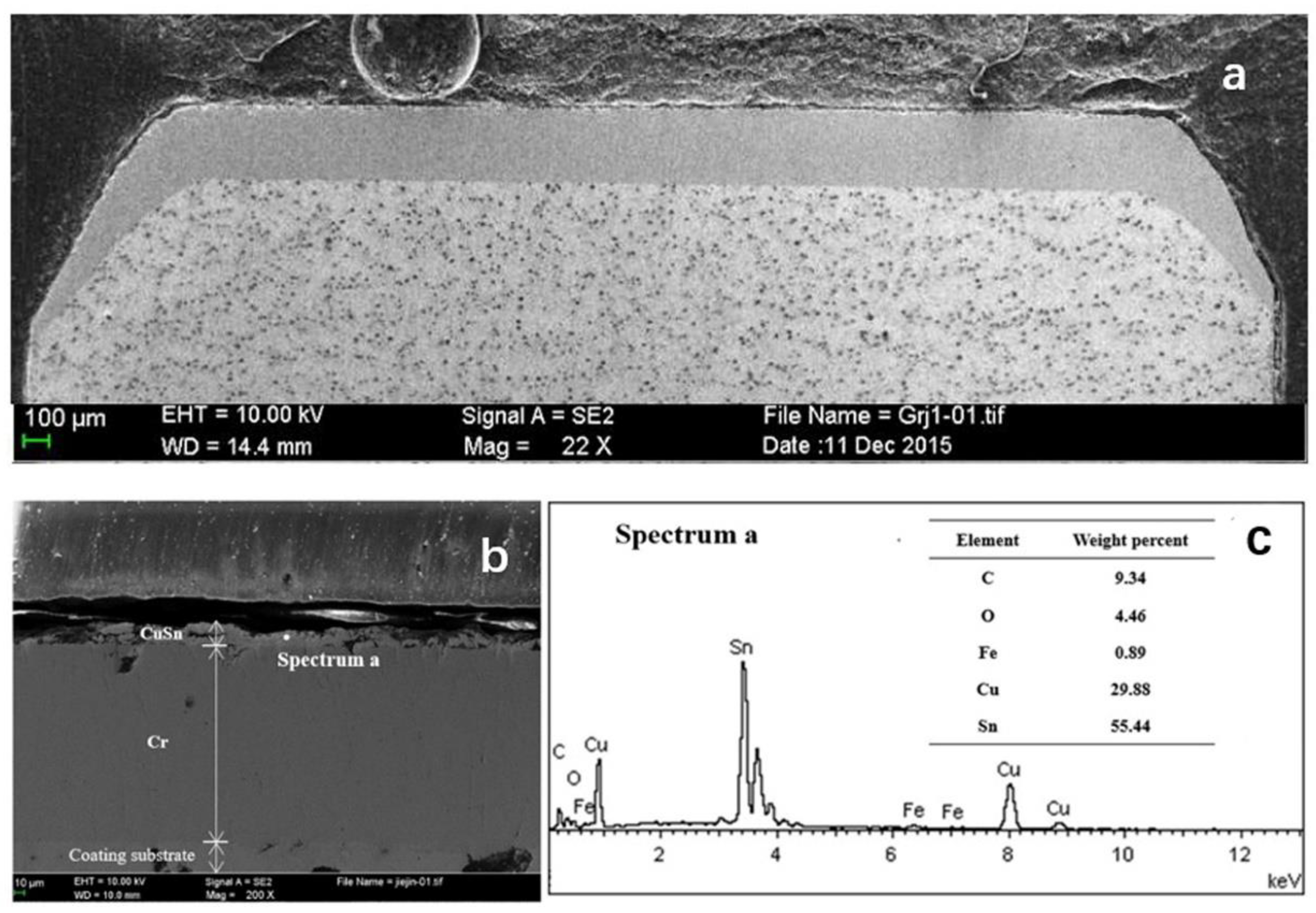
Figure 1. Structural profile (a), cross-section topography (b) and elemental contents (c) of the CuSn-Cr coated piston ring.
Metals 09 00139 g001
Figure 2. Surface topography of piston rings with Cr (a) and CuSn-Cr coatings (b).
Metals 09 00139 g002
Figure 3. Piston ring reciprocating cylinder liner test rig.
Metals 09 00139 g003
Figure 4. The friction force of a typical reciprocating stroke in the stable wear period.
Metals 09 00139 g004
Figure 5. The typical tested piston ring and cylinder liner (PRCL) samples.
Metals 09 00139 g005
Figure 6. Friction force variation of the CuSn-Cr/Fe and Cr/Fe pairs at the dead center.
Metals 09 00139 g006
Figure 7. Friction coefficient (a) and wear loss (b) of the CuSn-Cr/Fe and Cr/Fe pairs.
Metals 09 00139 g007
Figure 8. Surface topography (a), enlarged area topography (b) and position b (c) and position c (d) element contents of the cylinder liner matched with Cr coated piston ring.
Metals 09 00139 g008
Figure 9. Surface topography (a), enlarged area topography (b) and position d (c) and position e (d) element contents of the cylinder liner matched with CuSn-Cr coated piston ring.
Metals 09 00139 g009
Figure 10. Elemental distribution mapping on the worn surface of Figure 9b.
Metals 09 00139 g010
Figure 11. Surface topography (a), enlarged area topography (b) and position f (c) and position g (d) element contents of Cr coated piston ring.
Metals 09 00139 g011
Figure 12. Surface topography (a), enlarged area topography (b) and position h (c) and position i (d) element contents of CuSn-Cr coated piston ring.
Metals 09 00139 g012
Figure 13. Elemental distribution mapping on the worn surface of Figure 12b.
Metals 09 00139 g013
Table 1. Experimental conditions.
Experimental StageNominal Pressure (MPa)Temperature (°C)Time (h)
RLL7120~1.5
RHL56190~8
Table 2. Surface roughness measurements of the frictional pairs before and after the running-in test.
Frictional PairsSurface Roughness before Running-in Test (μm)Surface Roughness after Running-in Test (μm)
Cr/Fe0.25/1.070.20/0.35
CuSn-Cr/Fe13.67/1.090.16/0.28