Article

Influence of Explosive Ratio on Morphological and Structural Properties of Ti/Al Clads

1
Army Engineering University of PLA, Nanjing 21007, China
2
Jiangsu Runbang New Materials Group, Nanjing 201803, China
*
Author to whom correspondence should be addressed.
Metals 2019, 9(2), 119; https://doi.org/10.3390/met9020119
Submission received: 30 December 2018 / Revised: 19 January 2019 / Accepted: 22 January 2019 / Published: 24 January 2019
(This article belongs to the Special Issue Explosive Welding)

Abstract

:
The current work focuses on the effect of explosive ratio R on the comprehensive properties of Ti/Al clads manufactured via explosive welding. The lower and upper limits of explosive ratio, namely R1 and R2, were determined according to the R–δf (flyer plate thickness) welding window. Two TA2/1060 explosive cladding plates were successfully manufactured at the different explosive ratios. Microstructure investigation was conducted by optical microscopy (OM), scanning electron microscopy (SEM), and energy dispersive spectrometer (EDS). The small wave bonding interface was observed at R1, where the vortex structure containing the ingot structure appeared periodically. The bonding interface presented a big wave bonding morphology and a locally continuous melting layer at R2. Many prolonged grains and adiabatic shear bands (ASBs) were found near the interface for a greater explosive load. Intermetallic compounds were formed in the bonding zones of the two plates. The thickness of element diffusion area increased with an increasing explosive ratio. Comparative tests of mechanical properties indicated that the tensile shear strength at R1 was higher. The microhardness, tensile strength, and bending performance of the two plates are similar and acceptable. Tensile fracture analysis indicated the fracture mode at R1 was ductile fracture, while the explosive cladding plate at R2 had mainly ductile fracture with quasi-cleavage fracture as the supplement.

1. Introduction

Titanium and its alloys have excellent comprehensive properties of outstanding corrosion resistance, low specific gravity, and high specific strength, which makes them widely applied in the chemical and shipbuilding industries [1,2]. However, its relatively high price increases the production and application costs to a certain extent [3]. Aluminum alloys are the main lightweight structural materials [4]. Especially for 1xxx aluminum alloys, they have advantages in terms of production technology and price compared with other aluminum alloys [5]. Therefore, it is of great value to combine the characteristics of Ti and Al. Ti/Al bimetal clads can be used in many harsh environments, such as aerospace engineering and the defense industry, because it has many unique advantages, such as heat resistance, oxidation resistance, and specific strength [6,7]. In addition, Vecchio [8] reported that the specific stiffness of Ti-Al3Ti metallic–intermetallic laminate (MIL) composite was twice that of steel, and the MIL composite could be used as damping elements or to absorb blast energy. Moreover, replacing expensive titanium with relatively cheap aluminum can improve economic efficiency [9].
However, titanium is extremely chemically reactive at high temperatures and differs greatly from aluminum in its physical properties. The linear expansion coefficient of titanium is 1/3 of that of aluminum, while thermal conductivity of titanium is only 1/16 of that of aluminum [5,10]. These factors make it difficult for Ti and Al to form high quality joints in the welding process. Kahraman et al. [11] reported that titanium could generally be welded using solid-state welding methods. Explosive welding, which employs the huge energy of detonation to achieve bonding between two dissimilar metals, is considered as an efficient method for manufacturing Ti/Al clads due to its direct welding in one time and low cost [6,12]. Other reported technologies and methods include friction stir welding [13], laser welding [14], rapid solidification processing [15], and powder metallurgy [16].
Many scholars have carried out research on Ti/Al clads manufactured via explosive welding in recent years. Xia et al. [17] investigated the microstructure and mechanical properties of TA2–2A12 bimetals fabricated via explosive welding. They found that the interface presented a wavy bonding morphology, and a “trunk” structure existed at the bonding peak. No intermetallic compounds were formed in bonding zones. The twinning and recrystallization or the orientation of grains near the interface were shown by Transmission Electron Microscope (TEM) in their study. Bataev et al. [18] focused on Ti/Al multilayer explosive welding where 10 titanium plates and 11 aluminum plates were welded together. The 21-layer “Al-Al3Ti-Ti” composite material was finally fabricated by annealing for 100 h under an air atmosphere of 903 K. The structure at the bonding interface and the intermetallic layer growth were studied by X-Ray Diffraction (XRD), Transmission Electron Microscope (TEM) and Optical Microscopy (OM). It was reported in their paper that the complete dissolution of 1-mm thick aluminum plates was not reached during the annealing time (up to 100 h). Tension and impact strength tests were carried out. Similarly, Foadian et al. [19] found only TiAl3 phase existed in the bonding zones after the heat treatment of explosively welded Al-Ti multilayers which were annealed at 903 K for 70 h. Fronczek et al. [20] concentrated on the microstructure evolution of the Al/Ti interface at 825 K and various annealing times. The outcomes demonstrated that four different intermetallic phases (TiAl3, TiAl2, TiAl, and Ti3Al) and a peninsula-like morphology were found in the state directly after explosive welding, while the annealing process mainly caused growth of the TiAl3 phase as a continue layer. Microhardness tests showed the highest values in the range of 365–750 HV in vortex regions at the bonding interface after annealing. In addition, Li et al. [21] and Liu et al. [22] studied the explosive welding process of Ti/Al layered materials by numerical simulation to guide the actual production.
It is beneficial to reduce explosive charge during the explosive welding process, especially for the environment and cost. It is an ideal condition to use as few explosives as possible to obtain high quality explosive welded joints. In our previous study, we applied the “least action principle” in the course of the explosive welding of stainless steel/steel and proposed the lower limit rule of explosive charge [23]. Furthermore, we studied the mechanism of explosive welding from the perspective of dynamics [24]. The aim of the paper is to research the influence of the explosive ratio R on the comprehensive properties of Ti/Al clads manufactured via explosive welding. In this work, the R–δf (flyer plate thickness) welding window was proposed to determine the lower and upper limits of explosive ratio, namely R1 and R2, which were selected to manufacture the Ti/Al clads via explosive welding. Their microstructure and mechanical properties were examined. Few related studies have been reported up to now. The paper may provide guidance and support for the standardization production of Ti/Al explosive cladding.

2. Experimental Materials and Methods

The chemical composition of the flyer (TA2) and base (1060) plates are presented in Table 1. The size of 1060 is 550 mm × 250 mm × 14 mm (base plate), and that of TA2 is 620 mm × 290 mm × 2.5 mm (flyer plate). The low-detonation-velocity powdery emulsion explosive mixed with 38% quartz sand was employed, where the density ρ0, detonation velocity Dk, and the explosive effective multiparty index γ were 0.8 g/cm3, 2200 m/s, and 1.8, respectively. The detonation point was set at the short edge of the flyer plate. The schematic diagram of parallel explosive welding is shown in Figure 1. The distance between the flyer and base plates was 4 mm.
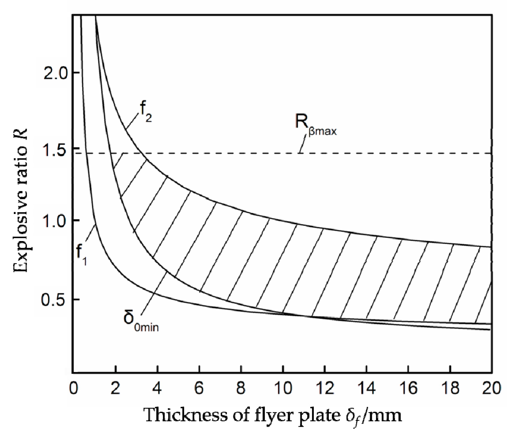
The Rδf welding window of Ti/Al explosive cladding was shown in Figure 2. The explosive ratio in explosive welding is the ratio of the explosive mass to the flyer plate mass per unit area, as indicated by Equation (1) [12]. The lower and upper limits of the explosive ratio curves (f1, f2) can be obtained based on Equation (2) and Equation (3) [25,26,27,28,29].
R = ρ 0 δ 0 ρ f δ f ,
δ f 1 = 2 W min ( γ 2 1 ) ( 5 + R min + 4 / R min ) 3 D k 2 ρ f R min ( 1 k 0 R 0 R min ) 2 ,
δ f 2 = 4.48 4 κ c t mp 2 V sf 3 ( γ 2 1 ) 2 ( 5 + R + 4 / R max ) 2 9 ρ f D k 8 R max 2 ( 1 k 0 R 0 R max ) 8 ,
sin β = 1 γ 2 1 ( 3 R 5 + R + 4 / R ) 1 2 ,
Here, ρf is the density of the flyer plate; ρ0 and δ0 are the density and thickness of explosives, respectively; Dk and γ are the detonation velocity and effective multiparty index of explosives, respectively; Rmin and Rmax are the minimum and maximum explosive ratios, respectively. Wmin is the minimum energy which can realize welding per unit area; R0 and k0 are the explosive characteristic constants; κ is the temperature conductivity coefficient; c is the specific heat capacity; tmp is the lower melting point of the welded materials; Vsf is the volume sound velocity of the flyer plate; β is the dynamic bent angle.
Explosives have a critical detonation thickness. When the thickness of explosives is less than the critical detonation thickness, the explosives cannot be detonated. The critical detonation thickness of the powdery emulsion explosive is approximately 12.5 mm. Thus, the curve δ0 min of the critical detonation thickness can be obtained using Equation (1). Furthermore, the explosive ratio R ranges from 0.12 to 1.46 based on Equation (4) because the value of the dynamic bent angle β ranges from π/36 to 5π/36 [29]. In this study, the thickness of flyer plate was 2.5 mm, so the lower and upper limits of explosive ratio could be determined to manufacture two TA2/1060 cladding plates, respectively, namely sample 1 (R1 = 0.96) and sample 2 (R2 = 1.46).
Samples for property tests were taken from the two plates by the wire electrical discharge machining method. Microstructure investigation of materials was carried out by using an IE200M optical microscope (OM) (SDPTOP, Ningbo, China) and a JSM-6360LV scanning electron microscope (SEM) (JEOL, Tokyo, Japan). Energy-dispersive X-ray spectroscopy (EDS) (EDAX Inc., Draper, UT, USA) analysis and lining scan test were constructed to analyze the diffusion of elements and the composition of specific parts. These samples used in microstructure studies were subjected to standard sanding, polishing, and etching (10% HF, 5% HNO3, and 5% HCl in water) [18]. Microhardness tests near the interface were measured by an MC010-HVS-1000 microhardness tester (WHW, Shanghai, China). A WE-1000B universal testing machine (HONGXING MACHINE, Shaoxing, China) was used to test the tensile strength, tensile shear strength, and bending performance according to GB/T 228.1-2010, GB/T 6396-2008, and GB/T 232-2010, respectively. The fracture morphology of the tensile samples was observed by an SEM.

3. Results and Discussion

3.1. Microstructure Investigation

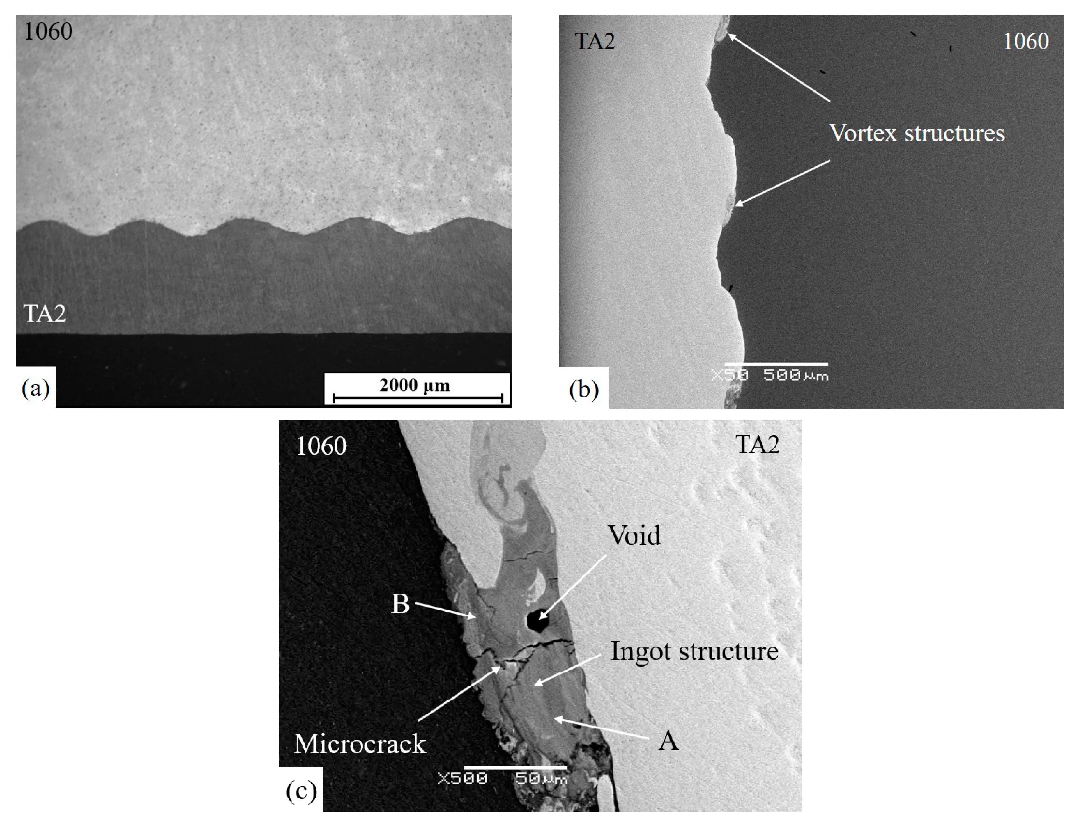
Figure 3a shows the typical small wave shape example of the bonding interface of sample 1 after explosive welding. No major defects, such as cracks or pores, were observed. Oxides and oxide layers of Ti and Al were not found in the interface zones either. The vortex structure, a typical characteristic of the wavy bonding interface, was formed periodically at the wave peaks in Figure 3b. When the flyer and base plates had a slanting collision, at the collision point, the flyer plate invaded the base plate, forming a depression. At the same time, the base plate formed a wave peak under the shear action of the metal jets in front of the collision point. Under the action of the large bending moment, high temperature, and high pressure produced by the explosion load, the bonding surface presented a fluid state. The flow of the flyer and base plates was rotated in the opposite direction, eventually forming the vortex structures. Generally speaking, wavy bonding interface is considered as an ideal interface morphology for its plastic deformation and increased bonding areas [30,31].
As shown in Figure 3c, the vortex structure of sample 1 contains an ingot structure. The ingot structure was the result of the molten metals being wrapped in the vortex structure at a high temperature. The formation of the ingot structure resulted in the absence of a continuous melting layer in the bonding interface, which was beneficial for the bonding strength of sample 1. Besides, some microcracks and voids could be seen in the ingot structure. Two factors may be considered to explain the phenomenon. On the one hand, a sharp change in temperature caused the molten metals at the interface to solidify rapidly. On the other hand, the high-temperature air and oxide films remaining at the interface were limited into the ingot structure under the action of the explosion.
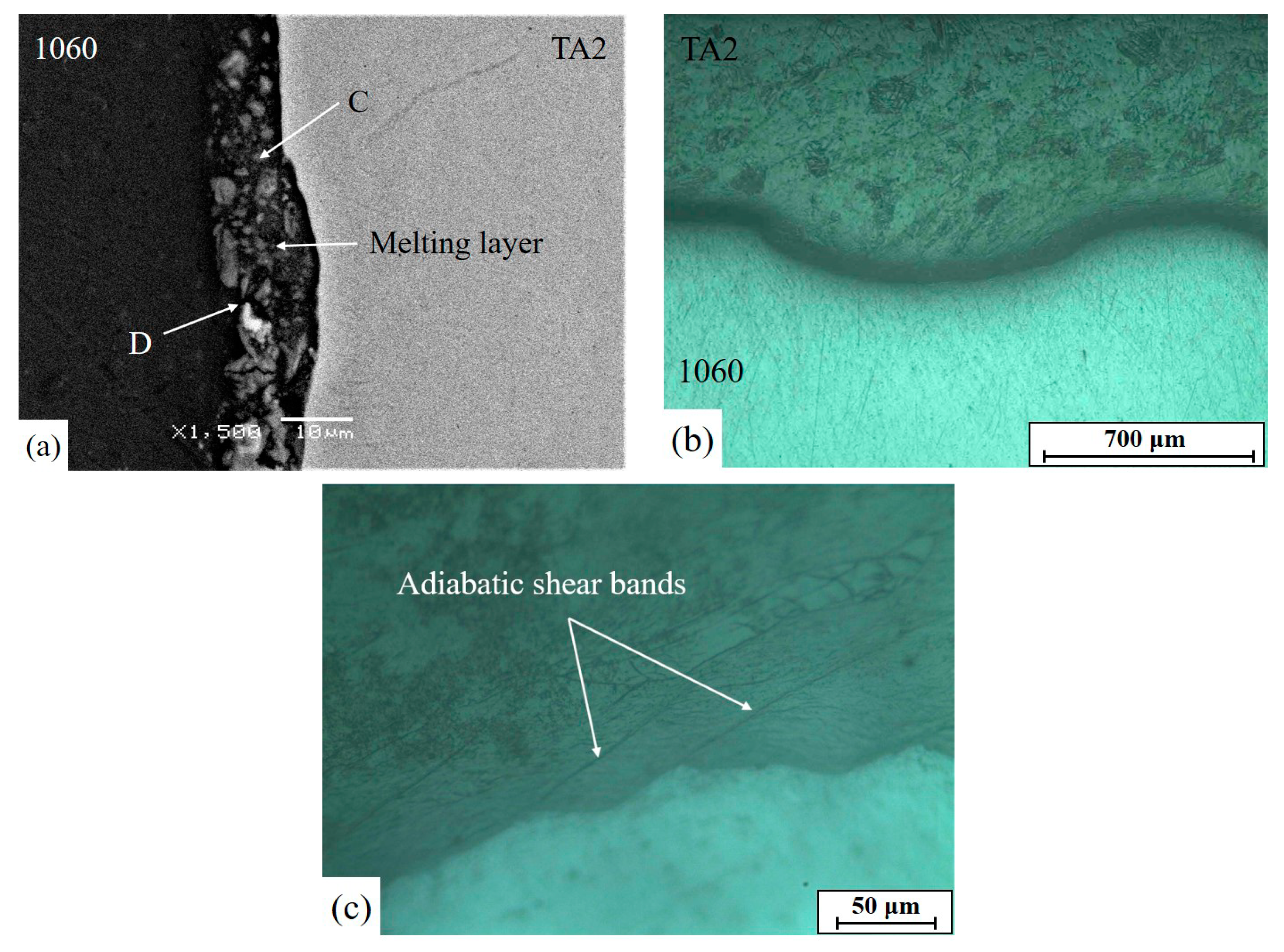
The significant melting layer of sample 2, about 12 μm, is shown in Figure 4a. As another typical interface morphology, the existence of melting layers can be attributed to the transformation of kinetic energy to heat energy [32]. The violent collision made the interface severely deformed, which produced a large amount of plastic deformation heat. Aluminum melted near the interface at high temperature and pressure due its much lower melting point than that of titanium. This is similar to reports in the literature, where melting zones appeared at the 2205/AZ31B bonding interface for the low melting point of AZ31B magnesium alloy [33]. Compared with the wave bonding morphology, the melting layer is not an acceptable interface morphology, especially for Ti/Al explosive cladding. The low solid solubility of Ti and Al in each other makes it possible to easily generate intermetallic compounds and mechanical mixtures in the melting layer, which can increase the brittleness of welded joints and deteriorate the mechanical properties [17,34].
In addition to the continuous melting layer, the big wave bonding morphology of sample 2 was observed in Figure 4b. The shape and distribution of the grains near the wave bonding interface had been changed significantly for the severe plastic deformation. The prolonged grains and small individual crystallites were randomly oriented. More dislocations and structural changes were observed on the TA2 side near the interface because the softening temperature of Ti was much higher than that of Al [17,18]. As shown in Figure 4c, there are some lines extending to the side of the flyer plates of sample 2, which are enveloped at the bonding interfaces—approximately 45° from the interfaces—and are called “adiabatic shear bands” (ASB). ASBs are extensions of the plastic deformation from the interfaces to the material matrix, in essence. As a type of crack source, ASBs represent a microscopic reaction of macrocracks at the bonding interface, consequently, adversely affecting the bonding strength of sample 2. The formation of the ASBs is mainly related to impact toughness Ak and explosion load [35]. Low impact toughness of Ti and Al easily causes the existence of ASBs at the bonding interface of Ti/Al explosive cladding. In comparison with the ASB distribution of sample 1, that of sample 2 is denser. The reason for the phenomenon is a more severe plastic deformation in sample 2 caused by the greater explosive load.
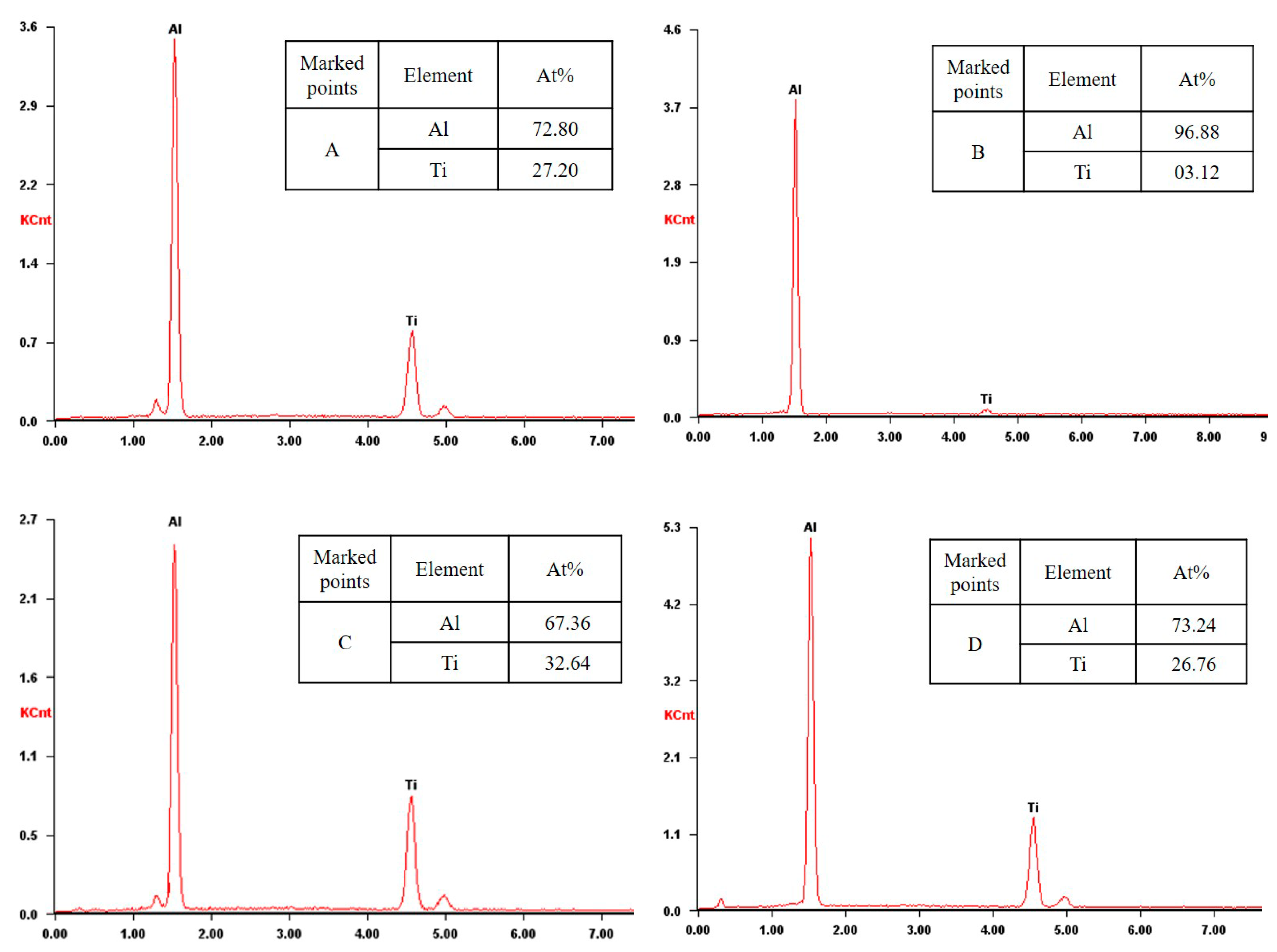
EDS analysis and lining scan test were carried out and the tested points are shown in Figure 3c and Figure 4a. The results presented in Figure 5 indicate that the element diffusion took place near the interfaces and the metal atoms were interlaced in the bonding zones. The average thickness of diffusion areas of the ingot structure and the melting layer was approximately 5.2 μm and 9.5 μm, respectively. The plastic deformation and the change of the element concentration gradient during the welding process are the main reasons for element diffusion near the interfaces. The atomic ratio of Ti and Al at the tested points are not constant (about 0.3 at points A and D or 0.5 at point C). The intermetallic compounds, such as TiAl3 and TiAl, existed in the ingot structure and the melting layer. The intense diffusion of atoms in the bonding zones easily made the element content reach the solid solution limit due to the low solid solubility of Ti and Al in each other under a high temperature and high pressure. Ultimately, these intermetallic compounds were formed in bonding zones. Almost only aluminum atoms were found at point B, which might result from the narrower diffusion area of the ingot structure. A certain degree of element diffusion can guarantee the bonding strength of the interface, but too large diffusion areas may increase the possibility of the formation of intermetallic compounds [17].
The results of microstructure investigations of sample 1 and sample 2 are shown in Table 2. Compared with sample 2, there were no obvious micro defects and large area melting of interface metals in the bonding zones of sample 1. The wavelength λ and amplitude A of the bonding interface of sample 1 were lower than those of sample 2. The bonding interface of sample 1 presented a small wave bonding morphology with a certain degree of plastic deformation and element diffusion. The bonding interface of sample 2 was severely deformed, including the formation of a melting layer and many ASBs. Therefore, the above results can indicate the rationality of a lower limit of the explosive ratio adopted.

3.2. Mechanical Tests

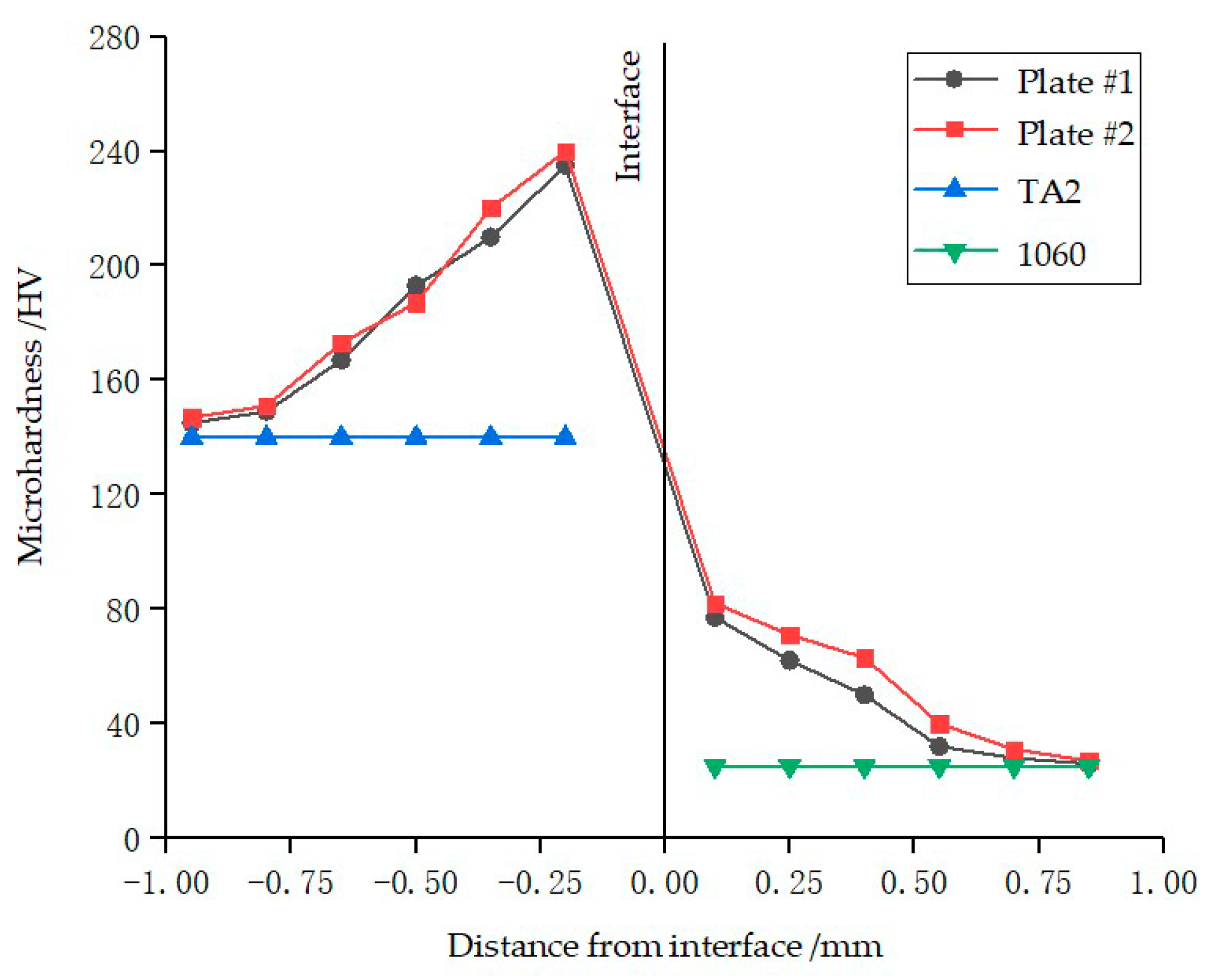
Microhardness characterizes the ability of the metal material to resist plastic deformation caused by external force indentation. The microhardness near the interfaces of sample 1 and sample 2 was measured via the indentation method. The distance between the tested points was 0.15 mm. The microhardness profiles near the interfaces are shown in Figure 6. The tested microhardness of sample 1 was in the ranges of 145 to 235 HV and 28 to 77 HV for Ti and Al, respectively, while that of sample 2 was in the ranges of 147 to 240 HV and 31 to 82 HV for Ti and Al, respectively. The values of the entire microhardness of the two plates were higher than the original values because plastic deformation near the interfaces led to the explosive hardening that occurred with explosion and collision. The existence of prolonged grains and small individual crystallites near the interfaces visible in Figure 4b indicates that explosive welding had a fine grain strengthening effect on the interfaces. The maximum microhardness value was obtained at the closest to the bonding interfaces for both sample 1 and sample 2. The parent metals were exposed to a large amount of energy produced by the explosion and maximum plastic deformation took place at the interfaces. Similarly, the entire microhardness value of sample 2 was slightly higher than that of sample 1, which was also due to the higher explosive ratio for sample 2.
The tensile samples shown in Figure 7 and Equation (5) are given according to the Chinese standard GB/T 228.1-2010. The original tensile strengths of TA2 and 1060 are 410 MPa and 135 MPa, respectively. The standard values of tensile strength of sample 1 and sample 2 can be obtained using Equation (5).
σ b = a b σ 1 + a f σ 2 a b + a f ,
Here ab and af are the thicknesses of the base and flyer plates, respectively; σ1, σ2, and σb are the tensile strengths of the base, flyer, and explosive cladding, respectively. The standard value is calculated to be 176.7 MPa by substituting σ1 = 135 MPa, σ2 = 410 MPa, ab = 14 mm, and af = 2.5 mm.
The tensile test was carried out and the results are shown in Table 3. The tensile strength values of the two plates were approximately the same and significantly higher than the standard values of TA2/1060 explosive cladding and 1060 plates. The phenomenon might result from two factors. Firstly, plastic deformation caused by the explosion load resulted in working hardening. The mutual cross-cutting action of dislocations increased the motion resistance when the matrix material was subjected to tensile stress. Secondly, fracture of Al and Ti occurred successively and delamination of the interface finally took place during the tensile process due to the difference in tensile strength and toughness between Ti and Al. Therefore, the tensile strength of the Ti/Al explosive cladding plate was higher than that of the Al plate, which was the weaker material. This result is consistent with the literature [33,36].
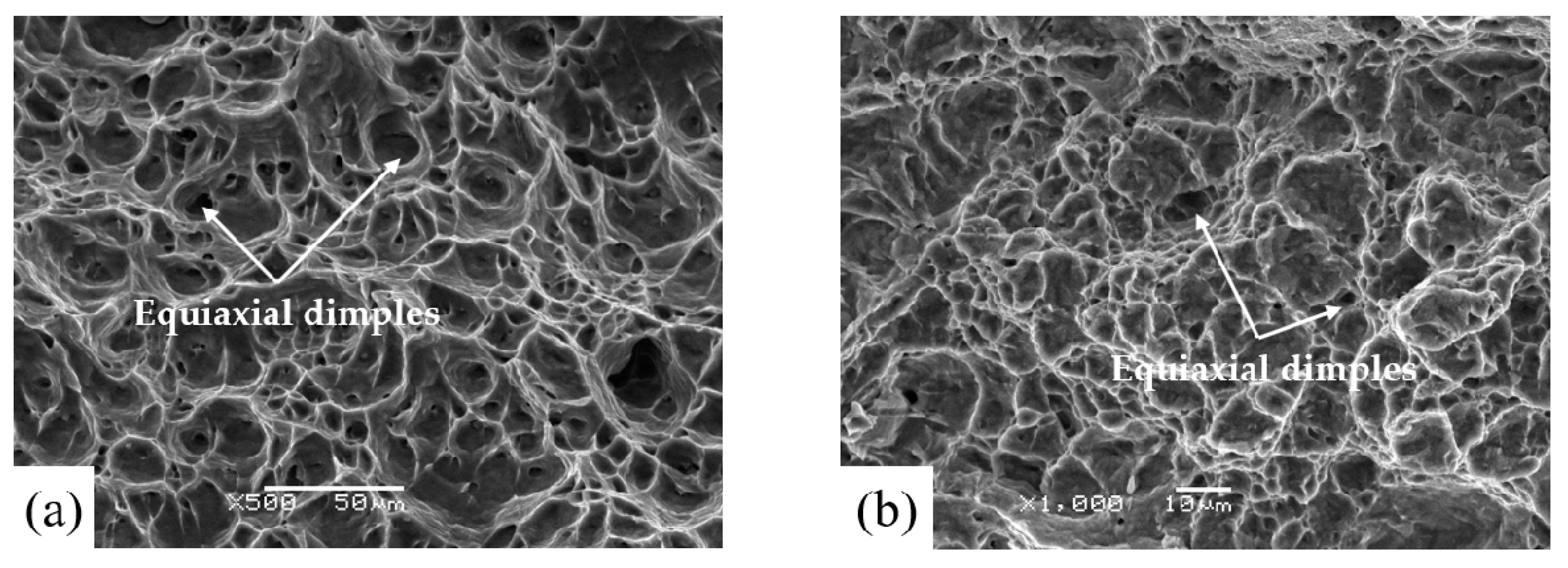
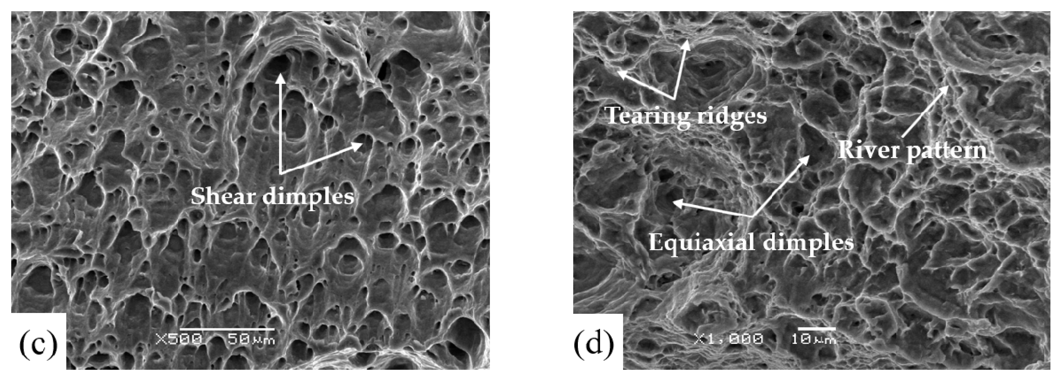
Figure 8a,b shows the tensile fracture morphology on the Al and Ti sides of the interface of sample 1, respectively. Several bumpy pits, known as dimples, were observed and the entire fractured surfaces presented a typical cup-and-cone morphology, which indicated that ductile fracture occurred in the tensile test. Under the action of tensile stress, plastic deformation took place and micropores were formed at the interfaces. With the increase of stress, the micropores grew gradually until the tensile sample fractured, eventually forming dimples. The dimple mode of the tensile samples of sample 1 was equiaxial dimple. A comparatively large number of shear dimples could be seen on the Al side of the interface of sample 2 (Figure 8c), which indicates that the matrix was subjected to both tensile stress and shear stress. In addition to dimples, a few tearing ridges and river patterns were also found on the Ti side of the interface of sample 2 (Figure 8d). As a result, the tensile samples of sample 2 had mainly ductile fracture with quasi-cleavage fracture as the supplement. Fracture analysis showed that the ductility of sample 1 was better than that of sample 2.
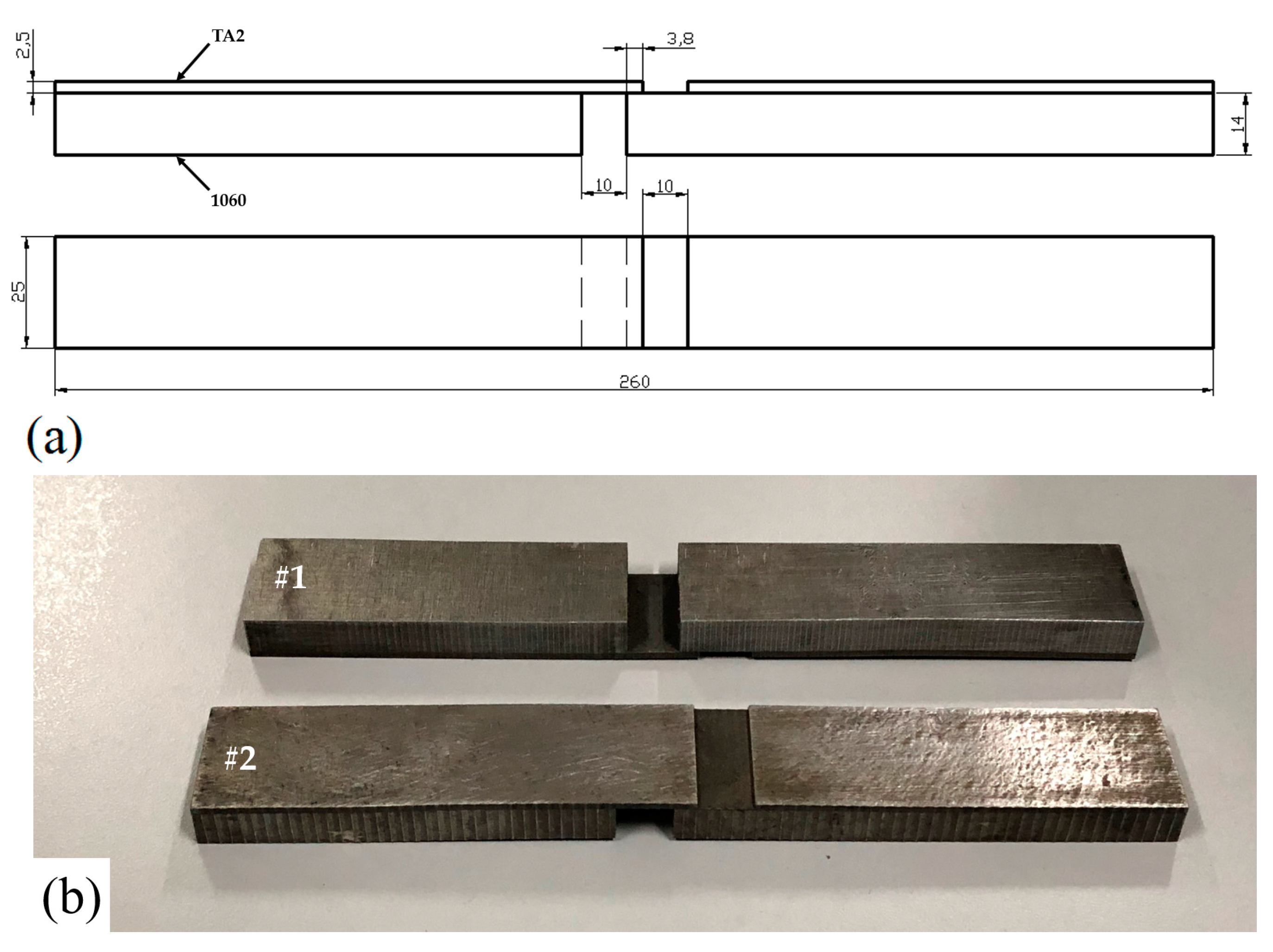
Tensile shear test was conducted to assess the interfacial bonding strength of sample 1 and sample 2. The tensile shear samples are presented in Figure 9b, which are prepared according to Chinese standard GB/T 6396-2008 (Figure 9a). The average tensile shear strength of sample 1 was 108.6 MPa, while that of sample 2 was 95.5 MPa. The former was larger than the latter by 13.7%. The separation of the samples occurred along the bonding interfaces between TA2 and 1060. Li and Wu [33] fabricated 2205/AZ31B laminates via explosive welding and found that the separation took place at the bonding interface after tensile shear test as well.
The above analysis showed that the locally continuous melting layer and wider diffusion area of sample 2 made it possible to form more intermetallic compounds. These brittle and hard phases adversely affected the interfacial bonding quality of sample 2. Moreover, under the action of tensile shear stress, many ASBs expanded into macroscopic cracks, which promoted the bonding interface of fracture and separation in sample 2. The result might indicate that the small wave bonding morphology of sample 1 was more acceptable for Ti/Al explosive cladding. This is coherent with the previous study [23].
Bending performance is an important mechanical property index of the two plates. The bending samples were obtained according to GB/T 232-2010, and bending tests were conducted. The bending samples were bent to 180°, and no delamination, fractures, and bonding defects were found. The result showed that both of the plates had good plasticity and toughness and satisfied the industrial production requirements. At the same time, we were able to indirectly determine that the content of hard and brittle intermetallic compounds in the bonding zones was not high.

4. Conclusions

1. The two TA2/1060 bimetal clads were successfully manufactured via explosive welding at different ratios.
2. The interfaces presented the wave bonding morphology. The wavelength and amplitude of the bonding interface increased at a higher explosive ratio due to more pressure.
3. Microstructure investigation showed that vortex structures and ingot structures were main typical interface microscopic features at the lower limit of the explosive ratio, while a locally continuous melting layer, more prolonged grains, and adiabatic shear bands were observed near the interface at the upper limit of the explosive ratio.
4. Element diffusion and intermetallic compounds were found in the bonding zones by EDS analysis and lining scan test.
5. The result of the tensile shear test showed that the tensile shear strength at the lower limit of the explosive ratio was larger than that at the upper limit of explosive ratio by 13.7%. The separation occurred along the bonding interfaces.
6. Microhardness values increased on both sides of the bonding interfaces and decreased with the increase of the distance from the interfaces. Tensile strength and bending performance were acceptable.

Author Contributions

Z.F. performed the experiment and wrote the paper. C.S. and Z.S. analyzed the experiment data and results, whereas H.S. provided technical information.

Funding

This research was funded by the National Natural Science Foundation of China (No. 51541112).

Acknowledgments

We are grateful to Jiangsu Runbang New Materials Group for providing the materials and experiment site for this work.

Conflicts of Interest

The authors declare no conflict of interest.

References

  1. Kahraman, N.; Gülenç, B.; Findik, F. Joining of titanium/stainless steel by explosive welding and effect on interface. J. Mater. Process. Technol. 2005, 169, 127–133. [Google Scholar] [CrossRef]
  2. Zu, G.Y.; Sun, X.; Zhang, J.H. Interfacial bonding mechanism and mechanical performance of Ti/Steel bimetallic clad sheet produced by explosive welding and annealing. Rare Met. Mater. Eng. 2017, 46, 906–911. [Google Scholar]
  3. Manikandan, P.; Hokamoto, K.; Fujita, M.; Raghukandan, K.; Tomoshige, R. Control of energetic conditions by employing interlayer of different thickness for explosive welding of titanium/304 stainless steel. J. Mater. Process. Technol. 2008, 195, 232–240. [Google Scholar] [CrossRef]
  4. Honarpisheh, M.; Asemabadi, M.; Sedighi, M. Investigation of annealing treatment on the interfacial properties of explosive-welded Al/Cu/Al multilayer. Mater. Des. 2012, 37, 122–127. [Google Scholar] [CrossRef]
  5. Li, Y.J. The Welding Technology of Advanced Materials, 1st ed.; Chemical Industry Press: Beijing, China, 2012; pp. 1–489. [Google Scholar]
  6. Findik, F. Recent developments in explosive welding. Mater. Des. 2011, 32, 1081–1093. [Google Scholar] [CrossRef]
  7. Guo, X.Z.; Fan, M.Y.; Liu, Z.L.; Ma, F.Y.; Wang, L.; Tao, J. Explosive cladding and hot pressing of Ti/Al/Ti laminates. Rare. Met. Mater. Eng. 2017, 46, 1192–1196. [Google Scholar]
  8. Vecchio, K.S. Synthetic multifunctional metallic–intermetallic laminate composites. JOM 2005, 57, 25–31. [Google Scholar] [CrossRef]
  9. Peng, L.M.; Wang, J.H.; Li, H.; Zhao, J.H.; He, L.H. Synthesis and microstructural characterization of Ti–Al3Ti metal–intermetallic laminate (MIL) composites. Scr. Mater. 2005, 52, 243–248. [Google Scholar] [CrossRef]
  10. Akca, E.; Gursel, A. The Effect of Diffusion Welding Parameters on the mechanical properties of Titanium alloy and Aluminum couples. Metals. 2017, 7, 22. [Google Scholar] [CrossRef]
  11. Kahraman, N.; Gulenc, B.; Findik, F. Corrosion and mechanical-microstructural aspects of dissimilar joints of Ti–6Al–4V and Al plates. Int. J. Impact Eng. 2007, 34, 1423–1432. [Google Scholar] [CrossRef]
  12. Lysak, V.I.; Kuzmin, S.V. Energy balance during explosive welding. J. Mater. Process. Technol. 2015, 222, 356–364. [Google Scholar] [CrossRef]
  13. Chen, Y.C.; Nakata, K. Microstructural characterization and mechanical properties in friction stir welding of aluminum and titanium dissimilar alloys. Mater. Des. 2009, 30, 469–474. [Google Scholar] [CrossRef]
  14. Vaidya, W.; Horstmann, M.; Ventzke, V.; Petrovski, B.; Koçak, M.; Kocik, R.; Tempus, G. Improving interfacial properties of a laser beam welded dissimilar joint of aluminium AA6056 and titanium Ti6Al4V for aeronautical applications. J. Mater. Sci. 2010, 45, 6242–6254. [Google Scholar] [CrossRef] [Green Version]
  15. Nayak, S.S.; Pabi, S.K.; Kim, D.H.; Murty, B.S. Microstructure-hardness relationship of Al–(L12)Al3Ti nanocomposites prepared by rapid solidification processing. Intermetallics. 2010, 18, 487–492. [Google Scholar] [CrossRef]
  16. Abbasi Chianeh, V.; Madaah Hosseini, H.R.; Nofar, M. Micro structural features and mechanical properties of Al–Al3Ti composite fabricated by in-situ powder metallurgy route. J. Alloys Compd. 2009, 473, 127–132. [Google Scholar] [CrossRef]
  17. Xia, H.B.; Wang, S.G.; Ben, H.F. Microstructure and mechanical properties of Ti/Al explosive cladding. Mater. Des. 2014, 56, 1014–1019. [Google Scholar] [CrossRef]
  18. Bataev, I.A.; Bataev, A.A.; Mali, V.I.; Pavliukova, D.V. Structural and mechanical properties of metallic-intermetallic laminate composites produced by explosive welding and annealing. Mater. Des. 2012, 35, 225–234. [Google Scholar] [CrossRef]
  19. Foadian, F.; Soltanieh, M.; Adeli, M.; Adeli, M.; Etminanbakhsh, M. A study on the formation of intermetallics during the heat treatment of explosively welded Al-Ti multilayers. Metall. Mater. Trans. A. 2014, 45, 1823–1832. [Google Scholar] [CrossRef]
  20. Fronczek, D.M.; Wojewoda-Budka, J.; Chulist, R.; Sypien, A.; Korneva, A.; Szulc, Z.; Schell, N.; Zieba, P. Structural properties of Ti/Al clads manufactured by explosive welding and annealing. Mater. Des. 2016, 91, 80–89. [Google Scholar] [CrossRef]
  21. Li, Y.; Liu, C.; Yu, H.; Zhao, F.; Wu, Z. Numerical simulation of Ti/Al bimetal composite fabricated by explosive welding. Metals 2017, 7, 407. [Google Scholar] [CrossRef]
  22. Liu, R.; Wang, W.; Zhang, T.; Yuan, X. Numerical study of Ti/Al/Mg three-layer plates on the interface behavior in explosive welding. Sci. Eng. Compos. Mater. 2016, 24, 833–843. [Google Scholar] [CrossRef]
  23. Shi, C.G.; Wang, Y.; Li, S.J.; You, J. Application and experiment on the least-action principle of explosive welding of stainless steel/steel. J. Iron Steel Res. Int. 2014, 21, 625–629. [Google Scholar] [CrossRef]
  24. Shi, C.G.; Wang, Y.; Zhao, L.S.; Hou, H.B.; Ge, Y.H. Detonation mechanism in double vertical explosive welding of stainless steel/steel. J. Iron Steel Res. Int. 2015, 22, 949–953. [Google Scholar] [CrossRef]
  25. Lysak, V.I.; Kuzmin, S.V. Lower boundary in metal explosive welding. Evolution of ideas. J. Mater. Process. Technol. 2012, 212, 150–156. [Google Scholar] [CrossRef]
  26. Vaidyanathan, P.V.; Ramanathan, A. Computer-aided design of explosive welding systems. J. Mater. Process. Technol. 1993, 38, 501–516. [Google Scholar] [CrossRef]
  27. Zhen, Y.M. The Principle and Application of Explosive Welding and Metallic Composite, 1st ed.; Central South University Press: Changsha, China, 2007; pp. 1–143. [Google Scholar]
  28. Yoshida, M.; Iida, M.; Tanaka, K.; Fujiwara, S.; Kusakabe, M.; Kusakabe, K. Detonation behavior of emulsion explosives containing glass microballoons. In Proceedings of the 8th International Symposium on Detonation, Albuquerque, NM, USA, 15–19 July 1985; pp. 171–177. [Google Scholar]
  29. Shao, B.H.; Zhang, K. Explosive Welding Principle and Its Application, 1st ed.; Dalian University of Science and Technology Press: Dalian, China, 1987; pp. 1–387. [Google Scholar]
  30. Akbari Mousavi, S.A.A.; Farhadi Sartangi, P. Experimental investigation of explosive welding of cp-titanium/AISI 304 stainless steel. Mater. Des. 2009, 30, 459–468. [Google Scholar] [CrossRef]
  31. Wronka, B. Testing of explosive welding and welded joints. Wavy character of the process and joint quality. Int. J. Impact Eng. 2011, 38, 309–313. [Google Scholar] [CrossRef]
  32. Acarer, M.; Gülenç, B.; Findik, F. Investigation of explosive welding parameters and their effects on microhardness and shear strength. Mater. Des. 2003, 24, 659–664. [Google Scholar] [CrossRef]
  33. Li, Y.; Wu, Z.S. Microstructural characteristics and mechanical properties of 2205/AZ31B laminates fabricated by explosive welding. Metals 2017, 7, 125. [Google Scholar] [CrossRef]
  34. Schuster, J.C.; Palm, M. Reassessment of the binary Aluminum-Titanium phase diagram. J. Phase Equilib. Diff. 2006, 27, 255–277. [Google Scholar] [CrossRef]
  35. Dodd, B.; Walley, S.M.; Yang, R.; Nesterenko, V.F. Major steps in the discovery of adiabatic shear bands. Metall. Mater. Trans. A 2015, 46, 4454–4458. [Google Scholar] [CrossRef]
  36. Zhang, N.; Wang, W.; Cao, X.; Wu, J. The effect of annealing on the interface microstructure and mechanical characteristics of AZ31B/AA6061 composite plates fabricated by explosive welding. Mater. Des. 2015, 65, 1100–1109. [Google Scholar] [CrossRef]
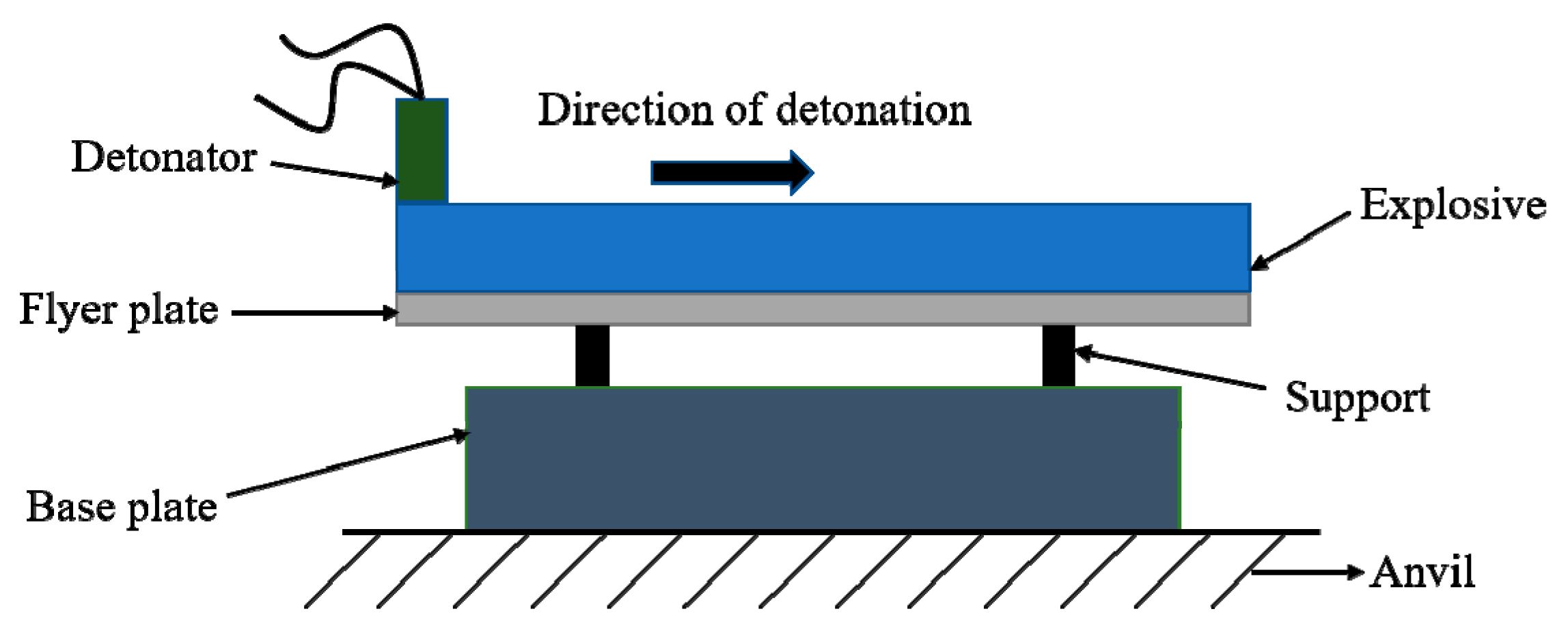
Figure 1. Parallel display of experimental set-up for explosive welding.
Metals 09 00119 g001
Figure 2. Rδf welding window of Ti/Al explosive cladding.
Metals 09 00119 g002
Figure 3. Microstructure of the bonding interface of sample 1: (a) small wave bonding interface; (b) vortex structures; (c) Ingot structure.
Metals 09 00119 g003
Figure 4. Microstructure of the bonding interface of sample 2: (a) melting layer; (b) big wave bonding interface; (c) adiabatic shear bands.
Metals 09 00119 g004
Figure 5. Energy spectrum analysis for bonding zones of sample 1 (marked points A and B) and sample 2 (marked points C and D).
Metals 09 00119 g005
Figure 6. Microhardness profiles near the interface.
Metals 09 00119 g006
Figure 7. Schematic diagram of tensile sample (unit: mm).
Metals 09 00119 g007
Figure 8. SEM (scanning electron microscopy) diagrams of fractures: (a) fracture in 1060 in sample 1; (b) fracture in TA2 in sample 1; (c) fracture in 1060 in sample 2; (d) fracture in TA2 in sample 2.
Metals 09 00119 g008aMetals 09 00119 g008b
Figure 9. Tensile shear test of sample 1 and sample 2: (a) schematic diagram of tensile shear sample (unit: mm); (b) tensile shear samples of sample 1 and sample 2.
Metals 09 00119 g009
Table 1. Chemical composition of experimental materials (wt%).
MaterialsChemical Composition (≤%)
TA2FeSiCNOHTi-
0.30.150.10.050.20.015Balanced-
1060FeSiCuMnMgZnTiAl
0.350.250.050.030.030.050.03Balanced
Table 2. The results of the microstructure investigation.
Tested Plateδ0/mmInterface Morphologyλ/μmA/μmDiffusion Area/μmMicrostructure
Vortex StructureMelting ASB
sample 114Small wave850–1100120–1405.2Regular appearanceIngot structureFew
sample 221Big wave and melting layer1550–1700230–2809.5FewMelting layerMany
Table 3. The results of the tensile strength test.
Tested PlateTensile Strength/MPaElongation/%
sample 1209.421.3
sample 2217.520.4