Comparison of Charge Storage Properties of Prussian Blue Analogues Containing Cobalt and Copper


Abstract
1. Introduction
2. Materials and Methods
3. Results
4. Discussion
5. Conclusions
Supplementary Materials
Author Contributions
Funding
Acknowledgments
Conflicts of Interest
References
- Karyakin, A.A. Prussian Blue and Its Analogues: Electrochemistry and Analytical Applications. Electroanalysis 2001, 13, 813–819. [Google Scholar] [CrossRef]
- De Tacconi, N.R.; Rajeshwar, K.; Lezna, R.O. Metal Hexacyanoferrates: Electrosynthesis, in Situ Characterization, and Applications. Chem. Mater. 2003, 15, 3046–3062. [Google Scholar] [CrossRef]
- Huggins, R.A. Review—A New Class of High Rate, Long Cycle Life, Aqueous Electrolyte Battery Electrodes. J. Electrochem. Soc. 2017, 164, A5031–A5036. [Google Scholar] [CrossRef]
- Ma, F.; Li, Q.; Wang, T.; Zhang, H.; Wu, G. Energy storage materials derived from Prussian blue analogues. Sci. Bull. 2017, 62, 358–368. [Google Scholar] [CrossRef]
- Paolella, A.; Faure, C.; Timoshevskii, V.; Marras, S.; Bertoni, G.; Guerfi, A.; Vijh, A.; Armand, M.; Zaghib, K. A review on hexacyanoferrate-based materials for energy storage and smart windows: Challenges and perspectives. J. Mater. Chem. A 2017, 5, 18919–18932. [Google Scholar] [CrossRef]
- Xing, Z.; Wang, S.; Yu, A.; Chen, Z. Aqueous intercalation-type electrode materials for grid-level energy storage: Beyond the limits of lithium and sodium. Nano Energy 2018, 50, 229–244. [Google Scholar] [CrossRef]
- Li, C.H.; Nanba, Y.; Asakura, D.; Okubo, M.; Talham, D.R. Li-ion and Na-ion insertion into size-controlled nickel hexacyanoferrate nanoparticles. RSC Adv. 2014, 4, 24955–24961. [Google Scholar] [CrossRef]
- Schwudke, D.; Stößer, R.; Scholz, F. Solid-state electrochemical, X-ray and spectroscopic characterization of substitutional solid solutions of iron–copper hexacyanoferrates. Electrochem. Commun. 2000, 2, 301–306. [Google Scholar] [CrossRef]
- Scholz, F.; Dostal, A. The Formal Potentials of Solid Metal Hexacyanometalates. Angew. Chem. Int. Ed. 1996, 34, 2685–2687. [Google Scholar] [CrossRef]
- Jayalakshmi, M.; Scholz, F. Charge–discharge characteristics of a solid-state Prussian blue secondary cell. J. Power Sources 2000, 87, 212–217. [Google Scholar] [CrossRef]
- Jayalakshmi, M.; Scholz, F. Performance characteristics of zinc hexacyanoferrate/Prussian blue and copper hexacyanoferrate/Prussian blue solid state secondary cells. J. Power Sources 2000, 91, 217–223. [Google Scholar] [CrossRef]
- Eftekhari, A. Fabrication of all-solid-state thin-film secondary cells using hexacyanometallate-based electrode materials. J. Power Sources 2004, 132, 291–295. [Google Scholar] [CrossRef]
- Widmann, A.; Kahlert, H.; Petrovic-Prelevic, I.; Wulff, H.; Yakhmi, J.V.; Bagkar, N.; Scholz, F. Structure, Insertion Electrochemistry, and Magnetic Properties of a New Type of Substitutional Solid Solutions of Copper, Nickel, and Iron Hexacyanoferrates/Hexacyanocobaltates. Inorg. Chem. 2002, 41, 5706–5715. [Google Scholar] [CrossRef] [PubMed]
- Widmann, A.; Kahlert, H.; Wulff, H.; Scholz, F. Electrochemical and mechanochemical formation of solid solutions of potassium copper(II)/zinc(II) hexacyanocobaltate(III)/hexacyanoferrate(III) KCux Zn1-x [hcc]x [hcf]1-x. J. Solid State Electrochem. 2005, 9, 380–389. [Google Scholar] [CrossRef]
- Wessells, C.D.; McDowell, M.T.; Peddada, S.V.; Pasta, M.; Huggins, R.A.; Cui, Y. Tunable Reaction Potentials in Open Framework Nanoparticle Battery Electrodes for Grid-Scale Energy Storage. ACS Nano 2012, 6, 1688–1694. [Google Scholar] [CrossRef]
- Okubo, M.; Honma, I. Ternary metal Prussian blue analogue nanoparticles as cathode materials for Li-ion batteries. Dalton Trans. 2013, 42, 15881–15884. [Google Scholar] [CrossRef]
- Yu, S.; Li, Y.; Lu, Y.; Xu, B.; Wang, Q.; Yan, M.; Jiang, Y. A promising cathode material of sodium iron–nickel hexacyanoferrate for sodium ion batteries. J. Power Sources 2015, 275, 45–49. [Google Scholar] [CrossRef]
- Xie, M.; Xu, M.; Huang, Y.; Chen, R.; Zhang, X.; Li, L.; Wu, F. Na2NixCo1−xFe(CN)6: A class of Prussian blue analogs with transition metal elements as cathode materials for sodium ion batteries. Electrochem. Commun. 2015, 59, 91–94. [Google Scholar] [CrossRef]
- Bocarsly, A.B.; Sinha, S. Chemically-derivatized nickel surfaces: Synthesis of a new class of stable electrode interfaces. J. Electroanal. Chem. Interfacial Electrochem. 1982, 137, 157–162. [Google Scholar] [CrossRef]
- Sinha, S.; Humphrey, B.D.; Bocarsly, A.B. Reaction of nickel electrode surfaces with anionic metal-cyanide complexes: Formation of precipitated surfaces. Inorg. Chem. 1984, 23, 203–212. [Google Scholar] [CrossRef]
- Humphrey, B.D.; Sinha, S.; Bocarsly, A.B. Diffuse reflectance spectroelectrochemistry as a probe of the chemically derivatized electrode interface. The derivatized nickel electrode. J. Phys. Chem. 1984, 88, 736–743. [Google Scholar] [CrossRef]
- Sinha, S.; Humphrey, B.D.; Fu, E.; Bocarsly, A.B. The coordination chemistry of chemically derivatized nickel surfaces generation of an electrochromic interface. J. Electroanal. Chem. Interfacial Electrochem. 1984, 162, 351–357. [Google Scholar] [CrossRef]
- Amos, L.J.; Schmidt, M.H.; Sinha, S.; Bocarsly, A.B. Overlayer-support interactions associated with the formation of a chemically modified interface: The nickel ferrocyanide derivatized nickel electrode. Langmuir 1986, 2, 559–561. [Google Scholar] [CrossRef]
- Amos, L.J.; Duggal, A.; Mirsky, E.J.; Ragonesi, P.; Bocarsly, A.B.; Fitzgerald-Bocarsly, P.A. Morphological variation at the [NiFe(CN)6]2−/− derivatized nickel electrode: A technique for the evaluation of alkali cation containing solutions. Anal. Chem. 1988, 60, 245–249. [Google Scholar] [CrossRef] [PubMed]
- Wozniak, N.R.; Frey, A.A.; Osterbur, L.W.; Boman, T.S.; Hampton, J.R. An electrochemical cell for the efficient turn around of wafer working electrodes. Rev. Sci. Instrum. 2010, 81, 034102. [Google Scholar] [CrossRef] [PubMed]
- Akiyama, T.; Fukushima, H. Recent Study on the Mechanism of the Electrodeposition of Iron-Group Metal-Alloys. ISIJ Int. 1992, 32, 787–798. [Google Scholar] [CrossRef]
- Grimmett, D.L.; Schwartz, M.; Nobe, K. A Comparison of DC and Pulsed Fe-Ni Alloy Deposits. J. Electrochem. Soc. 1993, 140, 973–978. [Google Scholar] [CrossRef]
- Sasaki, K.Y.; Talbot, J.B. Electrodeposition of Iron-Group Metals and Binary Alloys from Sulfate Baths I. Experimental Study. J. Electrochem. Soc. 1998, 145, 981–990. [Google Scholar] [CrossRef]
- Zech, N.; Podlaha, E.J.; Landolt, D. Anomalous codeposition of iron group metals I. Experimental results. J. Electrochem. Soc. 1999, 146, 2886–2891. [Google Scholar] [CrossRef]
- Oriňáková, R.; Turoňová, A.; Kladeková, D.; Gálová, M.; Smith, R.M. Recent developments in the electrodeposition of nickel and some nickel-based alloys. J. Appl. Electrochem. 2006, 36, 957–972. [Google Scholar] [CrossRef]
- Sun, L.; Chien, C.-L.; Searson, P.C. Fabrication of Nanoporous Nickel by Electrochemical Dealloying. Chem. Mater. 2004, 16, 3125–3129. [Google Scholar] [CrossRef]
- Liu, Z.; Guo, L.; Chien, C.-L.; Searson, P.C. Formation of a Core/Shell Microstructure in Cu-Ni Thin Films. J. Electrochem. Soc. 2008, 155, D569–D574. [Google Scholar] [CrossRef]
- Koboski, K.R.; Nelsen, E.F.; Hampton, J.R. Hydrogen evolution reaction measurements of dealloyed porous NiCu. Nanoscale Res. Lett. 2013, 8, 528. [Google Scholar] [CrossRef] [PubMed]
- Peecher, B.E.; Hampton, J.R. Dealloying Behavior of NiCo and NiCoCu Thin Films. Int. J. Electrochem. 2016, 2016, 2935035. [Google Scholar] [CrossRef]
- Bard, A.J.; Faulkner, L.R. Electrochemical Methods: Fundamentals and Applications, 2nd ed.; Wiley-Interscience: New York, NY, USA, 2001; ISBN 0-471-04372-9. [Google Scholar]
- Ardizzone, S.; Fregonara, G.; Trasatti, S. “Inner” and “outer” active surface of RuO2 electrodes. Electrochim. Acta 1990, 35, 263–267. [Google Scholar] [CrossRef]
- Baronetto, D.; Krstajić, N.; Trasatti, S. Reply to “note on a method to interrelate inner and outer electrode areas” by H. Vogt. Electrochim. Acta 1994, 39, 2359–2362. [Google Scholar] [CrossRef]
- Wang, J.; Polleux, J.; Lim, J.; Dunn, B. Pseudocapacitive Contributions to Electrochemical Energy Storage in TiO2 (Anatase) Nanoparticles. J. Phys. Chem. C 2007, 111, 14925–14931. [Google Scholar] [CrossRef]
- Yan, W.; Ayvazian, T.; Kim, J.; Liu, Y.; Donavan, K.C.; Xing, W.; Yang, Y.; Hemminger, J.C.; Penner, R.M. Mesoporous Manganese Oxide Nanowires for High-Capacity, High-Rate, Hybrid Electrical Energy Storage. ACS Nano 2011, 5, 8275–8287. [Google Scholar] [CrossRef]
- Duay, J.; Sherrill, S.A.; Gui, Z.; Gillette, E.; Lee, S.B. Self-Limiting Electrodeposition of Hierarchical MnO2 and M(OH)2/MnO2 Nanofibril/Nanowires: Mechanism and Supercapacitor Properties. ACS Nano 2013, 7, 1200–1214. [Google Scholar] [CrossRef]
- Augustyn, V.; Come, J.; Lowe, M.A.; Kim, J.W.; Taberna, P.-L.; Tolbert, S.H.; Abruña, H.D.; Simon, P.; Dunn, B. High-rate electrochemical energy storage through Li+ intercalation pseudocapacitance. Nat. Mater. 2013, 12, 518–522. [Google Scholar] [CrossRef]
- Sankar, K.V.; Surendran, S.; Pandi, K.; Allin, A.M.; Nithya, V.D.; Lee, Y.S.; Selvan, R.K. Studies on the electrochemical intercalation/de-intercalation mechanism of NiMn2O4 for high stable pseudocapacitor electrodes. RSC Adv. 2015, 5, 27649–27656. [Google Scholar] [CrossRef]
- Xia, C.; Guo, J.; Lei, Y.; Liang, H.; Zhao, C.; Alshareef, H.N. Rechargeable Aqueous Zinc-Ion Battery Based on Porous Framework Zinc Pyrovanadate Intercalation Cathode. Adv. Mater. 2018, 30, 1705580. [Google Scholar] [CrossRef] [PubMed]
- Li, B.; Xi, B.; Feng, Z.; Lin, Y.; Liu, J.; Feng, J.; Qian, Y.; Xiong, S. Hierarchical Porous Nanosheets Constructed by Graphene-Coated, Interconnected TiO2 Nanoparticles for Ultrafast Sodium Storage. Adv. Mater. 2018, 30, 1705788. [Google Scholar] [CrossRef] [PubMed]
- Li, H.; Lang, J.; Lei, S.; Chen, J.; Wang, K.; Liu, L.; Zhang, T.; Liu, W.; Yan, X. A High-Performance Sodium-Ion Hybrid Capacitor Constructed by Metal–Organic Framework–Derived Anode and Cathode Materials. Adv. Funct. Mater. 2018, 28, 1800757. [Google Scholar] [CrossRef]
- Dubal, D.; Jagadale, A.; Chodankar, N.R.; Kim, D.-H.; Gomez-Romero, P.; Holze, R. Polypyrrole Nanopipes as a Promising Cathode Material for Li-ion Batteries and Li-ion Capacitors: Two-in-One Approach. Energy Technol. 2019, 7, 193–200. [Google Scholar] [CrossRef]


| Set | |||||
|---|---|---|---|---|---|
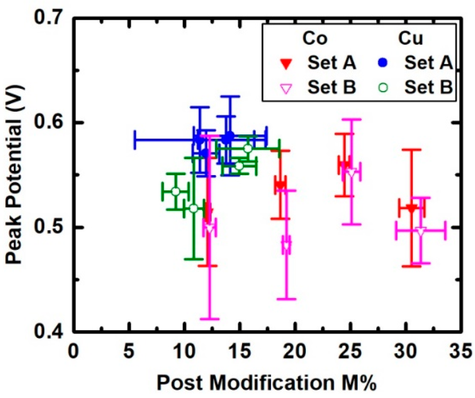
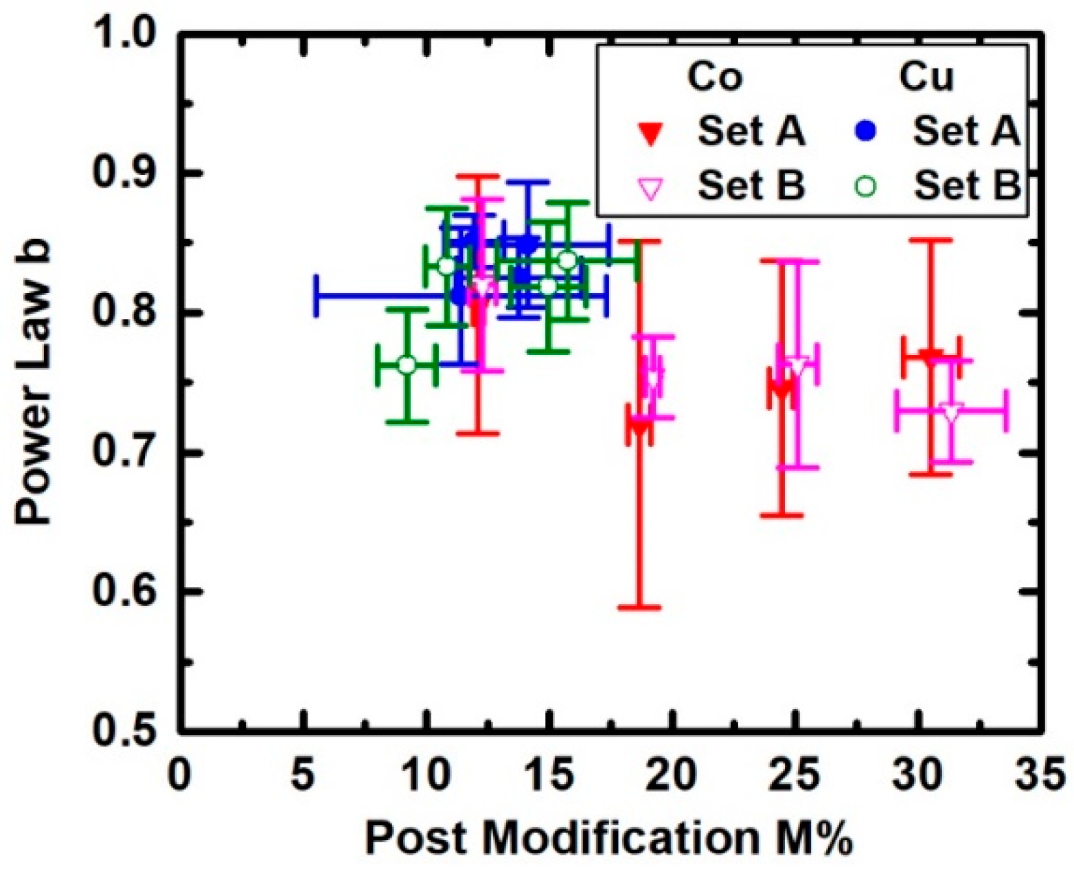
| NiCo Set A | 24 | 0.53 | 0.05 | 0.75 | 0.10 |
| NiCo Set B | 15 | 0.51 | 0.06 | 0.77 | 0.06 |
| NiCo Sets A & B | 39 | 0.52 | 0.05 | 0.76 | 0.09 |
| NiCu Set A | 24 | 0.58 | 0.03 | 0.84 | 0.03 |
| NiCu Set B | 14 | 0.55 | 0.03 | 0.83 | 0.04 |
| NiCu Sets A & B | 38 | 0.57 | 0.03 | 0.83 | 0.04 |
| Ni Set C | 4 | 0.537 | 0.024 | 0.713 | 0.012 |
© 2019 by the authors. Licensee MDPI, Basel, Switzerland. This article is an open access article distributed under the terms and conditions of the Creative Commons Attribution (CC BY) license (http://creativecommons.org/licenses/by/4.0/).
Share and Cite
Rensmo, A.; Hampton, J.R. Comparison of Charge Storage Properties of Prussian Blue Analogues Containing Cobalt and Copper. Metals 2019, 9, 1343. https://doi.org/10.3390/met9121343
Rensmo A, Hampton JR. Comparison of Charge Storage Properties of Prussian Blue Analogues Containing Cobalt and Copper. Metals. 2019; 9(12):1343. https://doi.org/10.3390/met9121343
Chicago/Turabian StyleRensmo, Amanda, and Jennifer R. Hampton. 2019. "Comparison of Charge Storage Properties of Prussian Blue Analogues Containing Cobalt and Copper" Metals 9, no. 12: 1343. https://doi.org/10.3390/met9121343
APA StyleRensmo, A., & Hampton, J. R. (2019). Comparison of Charge Storage Properties of Prussian Blue Analogues Containing Cobalt and Copper. Metals, 9(12), 1343. https://doi.org/10.3390/met9121343