Article

Effect of Si Addition on Mechanical and Electrochemical Properties of Al-Fe-Cu-La Alloy for Current Collector of Lithium Battery

1
School of Materials Science and Engineering, Shanghai Jiao Tong University, Shanghai 200240, China
2
Huafon NLM Al Co., Ltd., Shanghai 201506, China
3
Shanghai Huafon Materials Technology Institute, Shanghai 201203, China
*
Author to whom correspondence should be addressed.
Metals 2019, 9(10), 1072; https://doi.org/10.3390/met9101072
Submission received: 8 September 2019 / Revised: 25 September 2019 / Accepted: 27 September 2019 / Published: 1 October 2019
(This article belongs to the Special Issue Metals and Alloys for Energy Conversion and Storage Applications)

Abstract

:
The increasing demand for high-performance current collectors of lithium ion secondary batteries requires that the employed aluminum alloys have better mechanical properties and superior electrochemical performance. The effect of Si addition on the microstructure, tensile and electrochemical performance of Al-Fe-Cu-La alloy was investigated by optical microscopy, X-ray diffraction, scanning electron microscopy, a tensile test, conductivity test and Tafel polarization curve test. Experimental results indicated that Si addition to the Al-Fe-Cu-La alloy helped to refine the longitudinal grain size of the alloy. The Si-containing phase (AlFeSi) nucleated and grew along the surface of the AlFeLa phase. The Si addition to the Al-Fe-Cu-La alloy could greatly increase the tensile strength in the temperature range of −20 °C to 50 °C and improve high temperature stability of the alloy. Also, the addition of Si promoted the formation of the AlFeSi ternary phase, which helped to improve the corrosion resistance of the alloy.

1. Introduction

Although the electrical conductivity of aluminum is lower than that of copper, the weight of aluminum is half that of copper required to deliver the same amount of electricity. Undoubtedly, the use of aluminum current collectors helps to increase the energy density of lithium ion batteries. In addition, aluminum is cheaper than copper. At the same time, since aluminum is a relatively active metal, a dense oxide film is easily formed on the surface. During the charge/discharge cycle of the lithium ion battery, the oxide film on the surface of the aluminum current collector improves the corrosion resistance. Therefore, aluminum foil is often used as the current collector for positive active material (LiCoO2, LiCo1/3Ni1/3O1/3, LiMnO2) of the lithium ion battery [1]. It is worth noting that the drying temperature after coating the positive active material should be selected appropriately. Under the condition that the aluminum alloy foil has a certain conductivity, we can reduce the thickness of the aluminum alloy foil by increasing the strength of the aluminum foil, so that the surface of the aluminum alloy foil can be coated with more active material. As a result, the battery weight can be reduced and the specific energy of the lithium ion battery can be increased. Obviously, electrochemical performance and mechanical properties are particularly important for current collectors.
It is well known that the addition of rare earth elements to aluminum alloys can provide many benefits, such as refining grain size [2,3,4], affecting precipitation reactions [5,6], and so forth. Tsai et al. [7] found that the addition of less than 1.0 wt.% La resulted in complete modification of the eutectic Si phase. The eutectic Si of the A356 alloy was not well refined before the La content was close to 1.0 wt.% and the microstructure showed a fibrous silicon structure which was similar to the Sr-modified A356 alloy. The modification efficiency of the mechanical properties of the A356 alloy with 1.0 wt.% La was similar to that of the commercial modifier, Sr. Huang et al. [8] found that the eutectic Si crystals exhibited granular distribution and had the best mechanical properties when 0.3 wt.% La alloy was added.
To date, the addition of Si to Al-Fe-Cu-La alloy has not been reported. Therefore, the purpose of this paper is to evaluable the effect of Si addition on the microstructure, mechanical properties and electrochemical properties of Al-Fe-Cu-La alloy by optical microscopy, scanning electron microscopy, tensile test, conductivity test and Tafel polarization curve test.

2. Materials and Methods

The experimental materials were cold-rolled foils of Al-0.25Fe-0.1Cu-0.1La (wt.%), Al-0.25Fe-0.1Cu-0.1La-0.1Si (wt.%) and Al-0.25Fe-0.1Cu-0.1La-0.2Si (wt.%) aluminum alloy. The thickness of the foils was 0.07 mm. Considering the influence of drying temperature of the positive electrode coating process on the performance of the current collector, we conducted a pre-heat treatment of the cold-rolled current foil to simulate the influence of the pole piece drying process. The preparation process of the pole piece is followed by aluminum alloy piece, active material coating and pole piece drying. The pole piece coating refers to the process of uniformly coating stirred slurry on the current collector and drying the organic solvent in the slurry. The effect of the coating has an important effect on battery capacity, internal resistance, cycle life and safety. The choice of coating method and control parameters have an important effect on the performance of lithium ion batteries, mainly in the coating drying temperature control. The purpose is to remove a large amount of NMP (N-Methyl pyrrolidone) solvent in the slurry and the moisture therein. If the drying temperature is too low during coating, the pole piece cannot be completely dried. If the temperature is too high, the organic solvent inside the pole piece may evaporate too quickly and the surface coating of the pole piece may be cracked or peeled off. For the above reasons, we heat-treated the aluminum alloy foil at 160 °C for 10 h [9] after cold rolling.
The phase structure analysis of the alloy was carried out with X-ray diffractometer (XRD, Rigaku D/max 2500, Tokyo, Japan). The grain structure of the aluminum alloy foil was observed by optical microscope (OM, ZEISS imageA1m, Jean, Germany) under polarized light conditions. The microstructure of the alloy and the second phase particles were observed with scanning electron microscope (SEM, MIRA 3, TESCAN, Brno, Czech Republic) in backscatter mode. The corroded surface was observed by scanning electron microscope (SEM, VEGA 3 (LaB6), TESCAN, Brno, Czech Republic) in secondary electron mode. The composition of the second phase particles and the corroded surface is analyzed by energy dispersive X-ray spectroscopy (EDS, Aztec X-MaxN80, TESCAN, Brno, Czech Republic). The fracture surface of the tensile specimen was observed with scanning electron microscope (SEM, SIRION 200, FEI, Hillsboro, OR, USA), and the component of the fracture surface was analyzed by energy dispersive X-ray spectroscopy (EDS, INCA X-Act, FEI, Hillsboro, OR, USA).
Tensile tests were carried out on the universal material testing machine (Zwick/ROELL Z020, Zwick Roell Group, Ulm, Germany) at 25 °C. The tensile speed was 1 mm/min. The high/low temperature tensile tests were carried out with the electromechanical universal testing machine (CMT 5105, Meters Testing Machine Factory, Tianjin, China). The corresponding tensile speed was 1 mm/min. The conductivity of the material was tested by SIGATEST 2.069 at 25 °C.
The electrochemical performance was measured by Tafel polarization testing with 3.5 wt.% NaCl solution at 25 °C. The test sample was obtained by ultrasonic cleaning with acetone. The Tafel polarization curve test was performed with a three-electrode system with a CHI660C (Shanghai Chenhua Instrument Company, Shanghai, China) panel. The working electrode, the reference electrode and the counter electrode are respectively sample, saturated calomel electrode and platinum, respectively. The scan of the test was scanned from −1 V to 0 V at the rate of 1 mV/s.

3. Results and Discussion
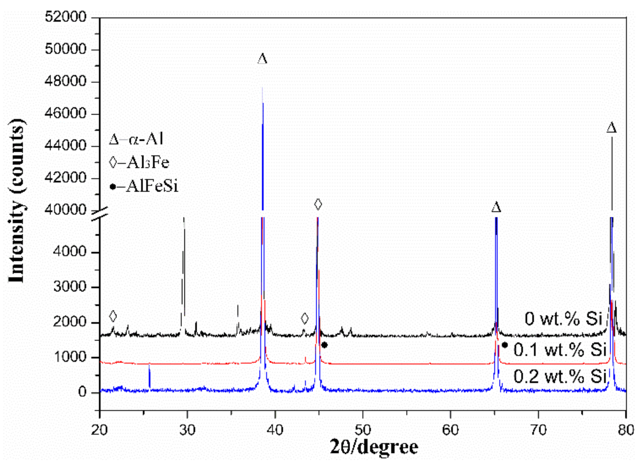
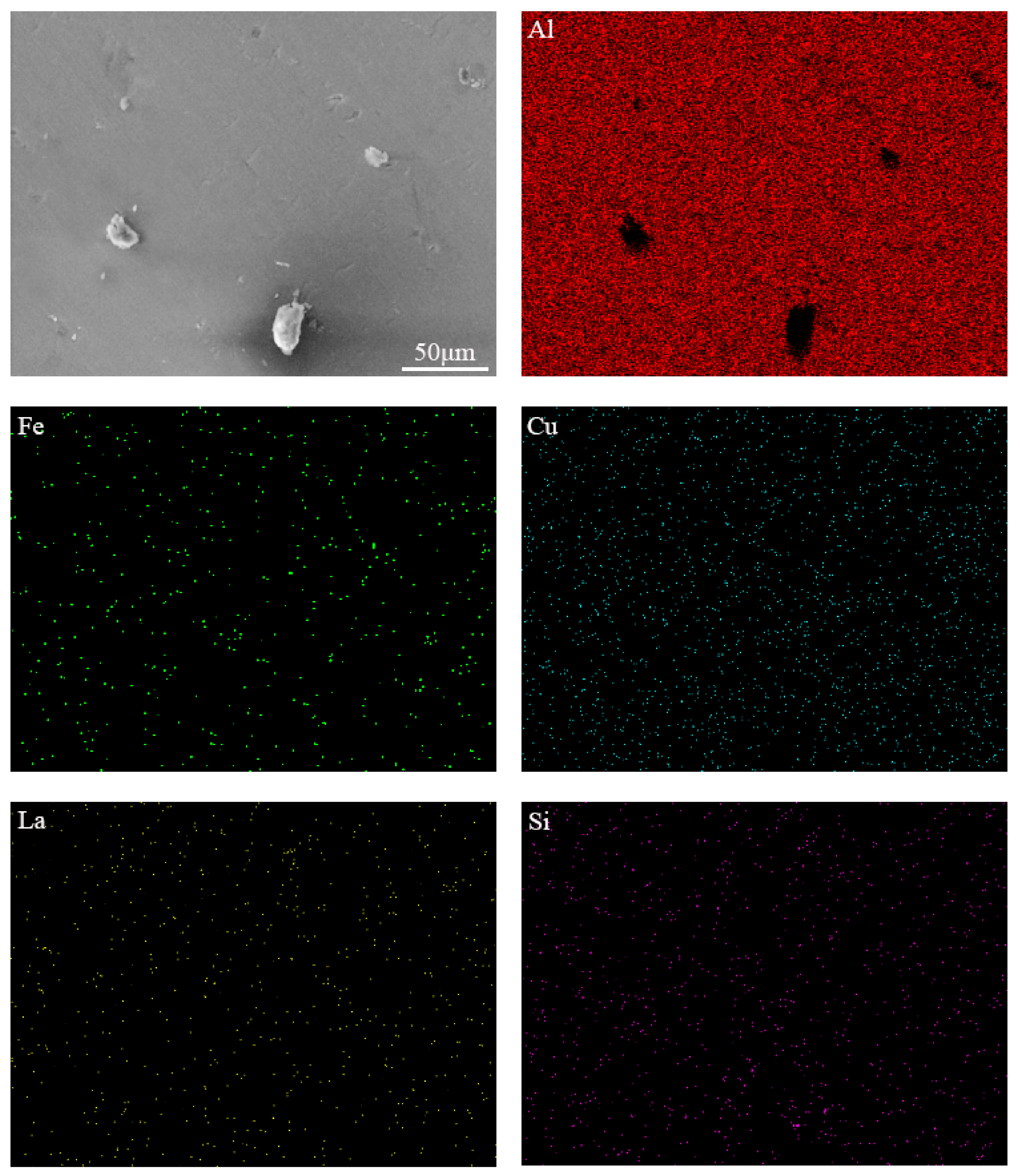
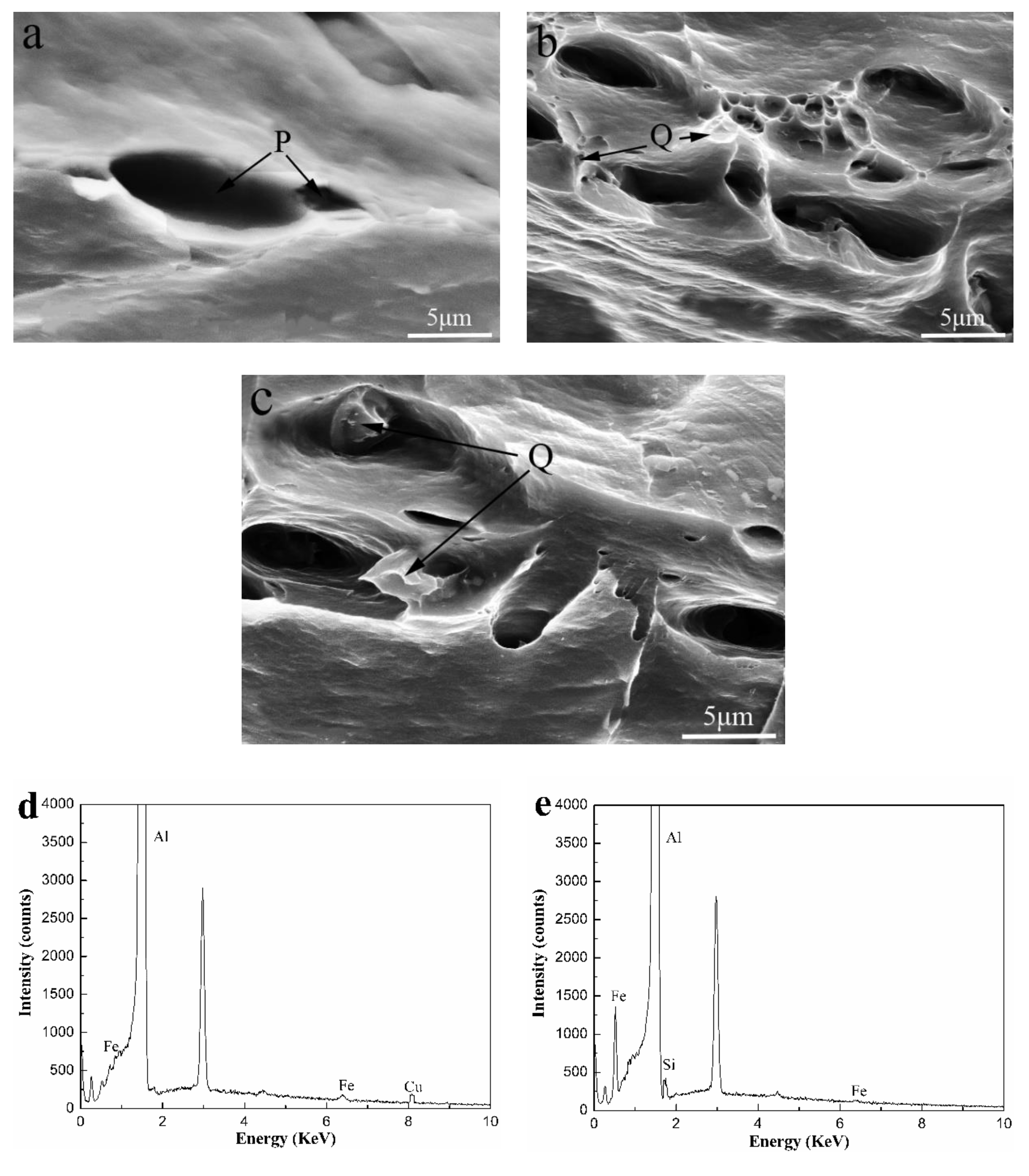
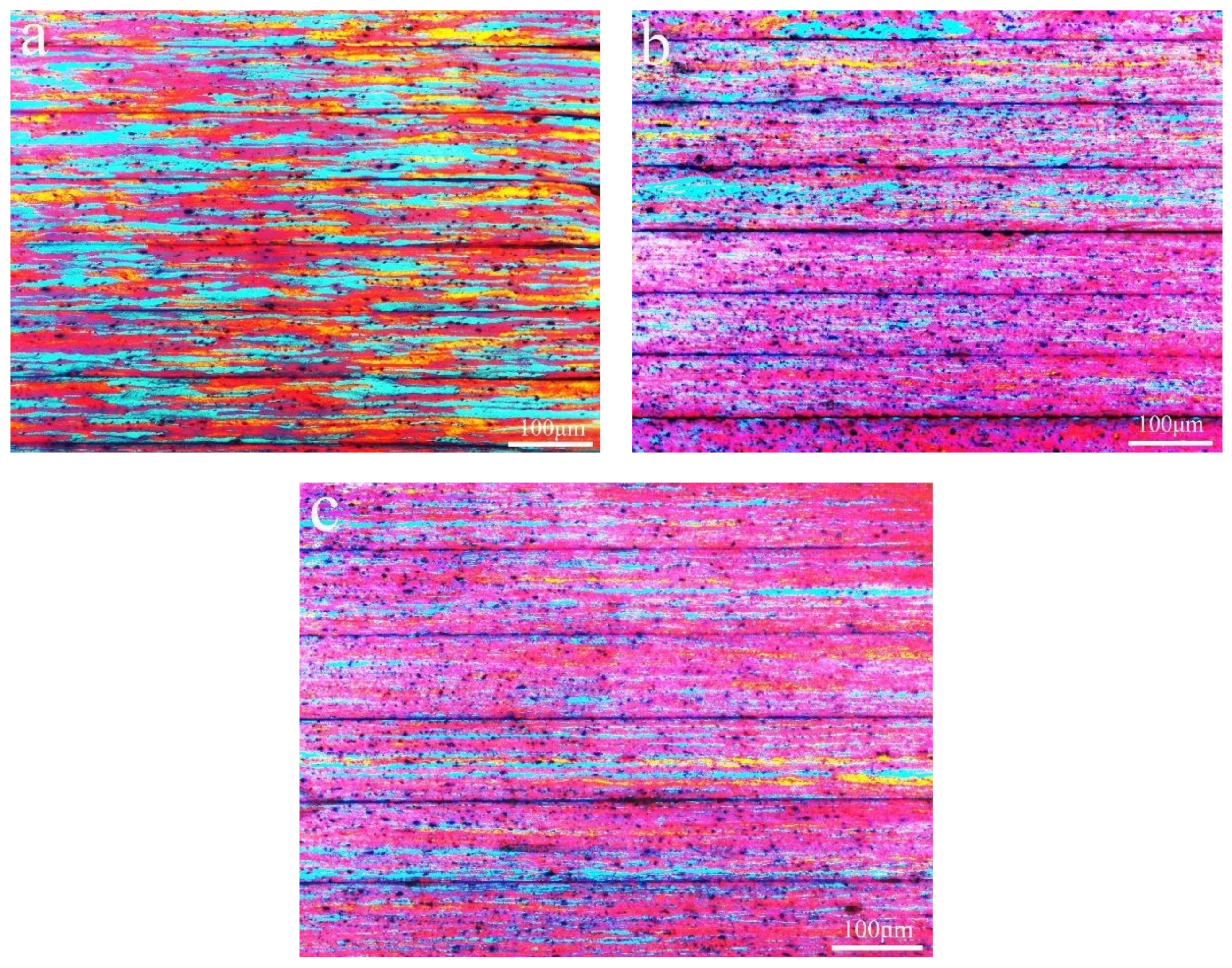
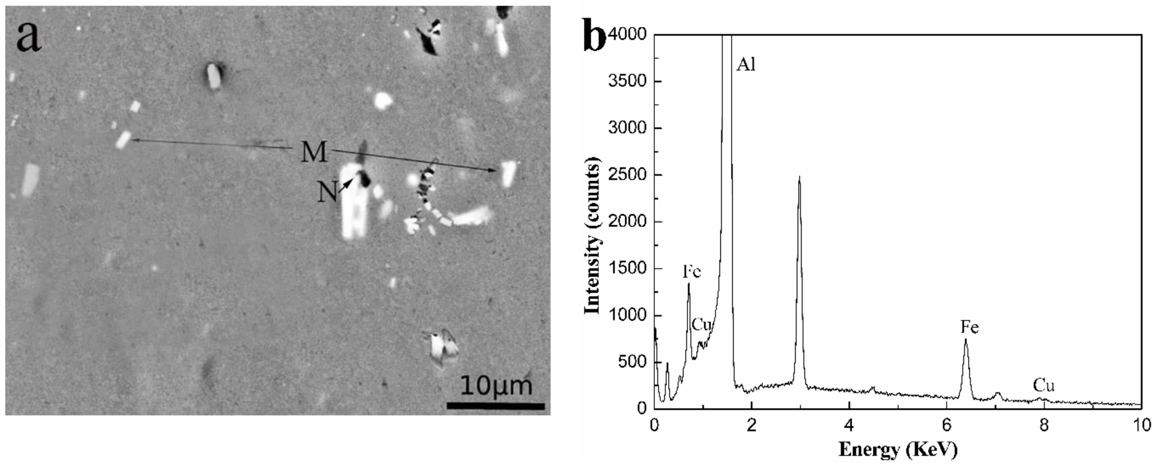
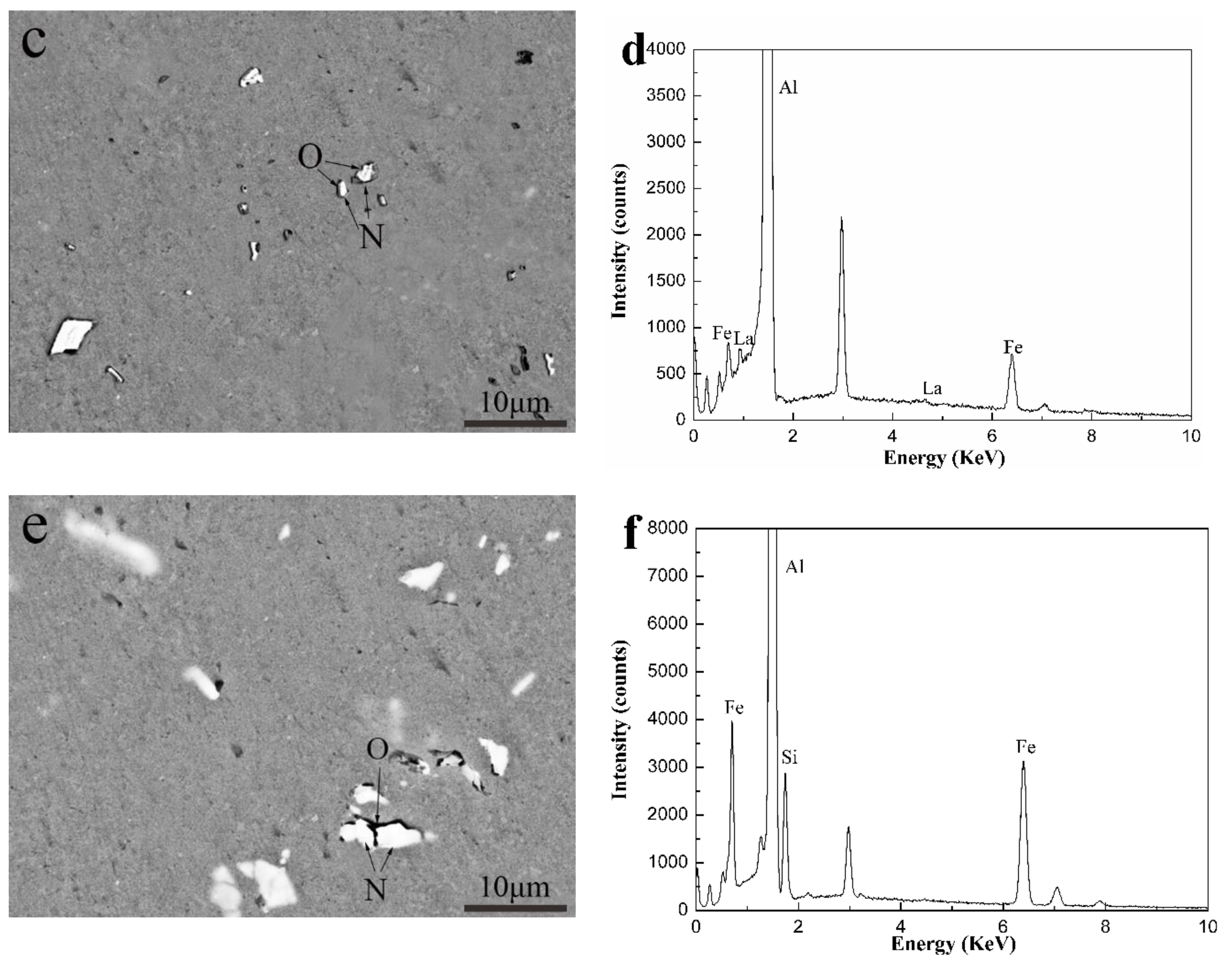
3.1. Microstructure

Figure 1 shows the longitudinal section microstructure of Al-0.25Fe-0.1Cu-0.1La alloys with different Si content. Due to the rolling force during the rolling process, the grains are shown along the rolling direction. We could observe that the Si-containing alloys had uniform grain size distribution and finer grain size compared to the matrix alloy without Si element, and the average grain size obtained by using Image Pro Plus (IPP6.0, Media Cybernetics, Washington D.C., USA) software are 43.87 μm (0 wt.% Si), 16.66 μm (0.1 wt.% Si), 19.01 μm (0.2 wt.% Si), indicating that trace of Si element can promote the grain refinement of the aluminum [10]. This also implied that alloys with Si element may have better mechanical properties. Simultaneously, as the grain size decreased the number of grain boundaries increased, which caused an increase of electron scattering, which adversely affected the electrical conductivity of the alloy. Although the grain boundary was a factor affecting the conductivity of aluminum alloy, grain boundaries had less influence on the conductivity. In this experiment, it was also well verified that the conductivity of 0.1 wt.% Si-containing alloy (57.01% International Annealed Copper Standard (IACS)) and 0.2 wt.% Si-containing alloy (58.45% IACS) is slightly lower than that of Si-free alloy (60.45% IACS) at 25 °C.
Figure 2 shows XRD patterns of Al-0.25Fe-0.1Cu-0.1La alloys with different Si content. We could find that the α-Al matrix and Al3Fe phase [11] are present in the alloys. This indicated that the commonly dispersed phase such as Al3Fe phase cannot be completely dissolved in the α-Al matrix during the smelting rolling process [12]. Due to the very low solid solubility of the Fe element in the aluminum matrix, it is mainly in the form of second phase intermetallic particles. The phase diagram of Al-Fe shows the maximum solubility of about 0.04 wt.% at 655 °C. Under equilibrium conditions, supersaturated Fe will exist as Al3Fe phase. Usually, we could observe the most intense Al peak at 38 degrees. Compared to the Si-free alloy, we could find the new phase of AlFeSi in the Si-containing alloy. The possible reason is that the growth free energy of the AlFeSi ternary phase was lower than that of the AlFe binary phase [13,14,15]. Therefore, the addition of Si element can significantly reduce the free energy of the whole system, and the AlFe binary phase tends to shift to the AlFeSi ternary phase.
The AlFeSi phase formed through the addition of Si to the Al-0.25Fe-0.1Cu-0.1La alloy. To distinguish these phases, we used SEM observation and EDS analysis to define the phases in the alloys. Figure 3 shows the backscattered photograph of three aluminum alloys.
In Figure 3 we can see the gray α-Al matrix, white particles of different shapes, including the tightness of the sphere, the rod shape and the irregularity in the three kinds of alloys. Combined with the experimental results of XRD and EDS, in Figure 3, phase M was identified as the AlFeCu [16] phase, phases N was confirmed to be the AlFeLa [17,18] phase, and phase O was determined as the AlFeSi phase. As shown in Figure 3, we could see that due to the addition of Si, the bright white near rod-shaped AlFeLa phases disappears. This might suggest that AlFeLa (Figure 3a), which was bright white near rod-shaped, tends to transition to the pale white irregular AlFeLa (Figure 3c,e). The difference in color appearance of the two kinds of AlFeLa and AlFeSi phases was caused by the alloying of the higher atomic number La, which provides a simple method for distinguishing the two phases. We observe that the AlFeSi phase tends to form around the AlFeLa phase. This might promote the spheroidization of AlFeLa phase. As a result, it might be beneficial for the second phase strengthening.
Figure 4 shows the EDS mapping of Al, Fe, Cu, La, Si elements of Al-0.25Fe-0.1Cu-0.1La-0.1Si alloy. It can be seen that the black AlFeSi phase tended to be dispersed around the white AlFeLa phase. The establishment of the black-white duplex phase indicated that the AlFeLa phase acted as a favorable nucleation site for the AlFeSi phase. The nucleation and growth process of the AlFeSi phase could be described as follows. First, the AlFeSi phase nucleated on the surface of the AlFeLa phase during solidification and then the AlFeSi phase grew along the surface of the AlFeLa phase. The AlFeSi phase grew around AlFeLa phase to form the core/shell structure similar to the core/shell structure of Ce-containing aluminum alloys [19]. As a result, the growth of the AlFeLa phase could be suppressed and the size of the precipitate could be refined in the Si-containing alloy. It is well known that the formation of large compounds not only reduced the strength but also adversely affected fatigue and impact toughness. At the same time, the finely distributed phase inhibited recrystallization, while the coarsely distributed phase promoted recrystallization.

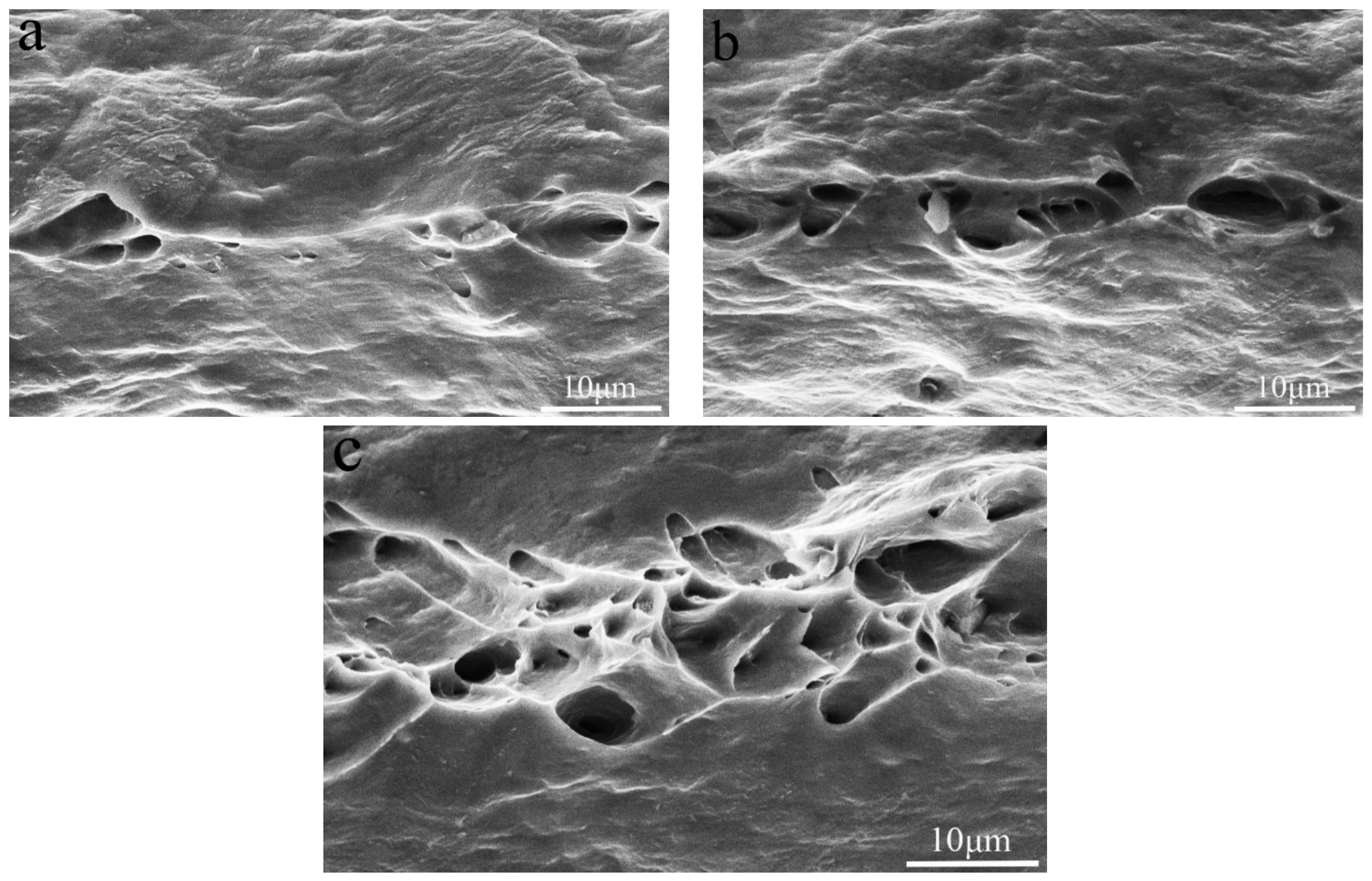
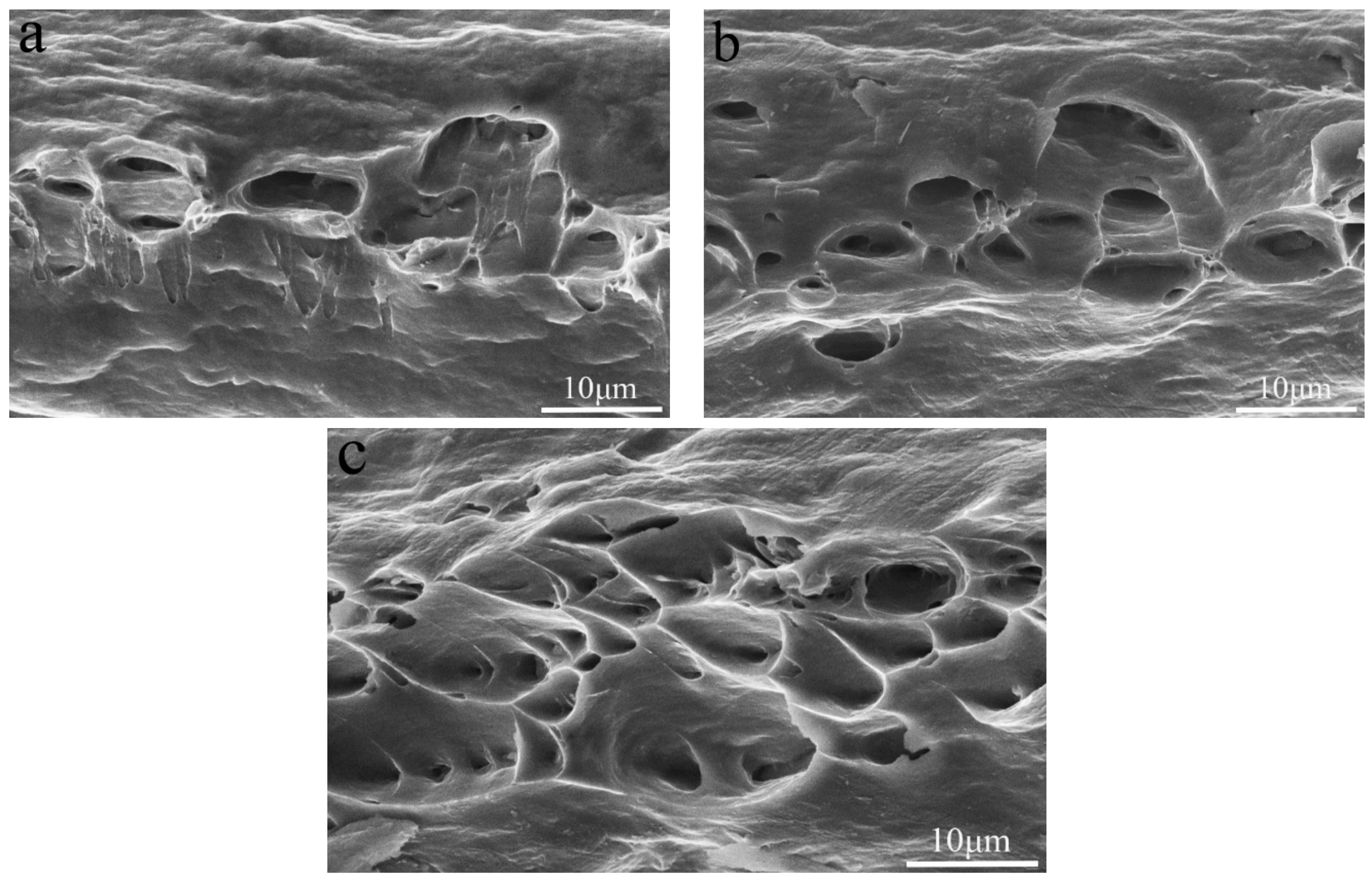
3.2. Mechanical Properties

The results of the tensile test at different temperatures are presented in Table 1. With the addition of 0.1 wt.% Si, the yield strength and tensile strength of the Si-containing alloy tested at 25 °C increased by more than 30% and 23%, respectively, compared to the Si-free alloy. The main reason for the increase in strength was that the effect of fine grain strengthening enhanced due to the addition of Si. Meanwhile, we see that the elongation has dropped by less than 1% due to the addition of Si element. Figure 5 shows an SEM image of the fracture surface in the longitudinal direction tested at 25 °C. Compared to the Si-free alloys, Si-containing alloys had more deep dimples and more residual phases were observed in the dimples. Combined with the SEM image (Figure 5) and EDS analysis of the fracture surface, we determined that the locations P and Q in Figure 5 were residuals of AlFeCu phase and AlFeSi phase, respectively. It is well known that brittle fracture is more likely to occur around hard intermetallic compound dispersed in the matrix than homogeneous matrix.
Like all rechargeable batteries, lithium ion batteries are also limited in terms of use but lithium ion batteries are different from ordinary rechargeable batteries. They were very delicate and more demanding than other batteries. Lithium ion batteries used in terminal equipment could be used in the range of 0 °C to 35 °C, 16 °C to 25 °C was the ideal operating temperature range and they could be stored in the range of −20 °C to 45 °C under certain restrictions. Charging or storing in the high temperature environment might permanently damage the battery capacity and further accelerated battery life degradation. Therefore, we simulated the current environment of the current collector by performing high temperature stretching at 50 °C and low temperature stretching at −20 °C for the above three alloys. The results are also shown in Table 1. It showed that the mechanical properties of the Al-0.25Fe-0.1Cu-0.1La alloy were greatly improved when 0.1% Si was added. At 50 °C, the elongation of the Si-free and Si-containing alloys remained almost the same as that at 25 °C, and the tensile strength decreased by 6.98% (0 wt.%Si), 6.79% (0.1 wt.%Si) and 7.94% (0.2 wt.%Si), respectively. The tensile strength increased by 9.09% (0 wt.%Si), 5.02% (0.1 wt.%Si) and 4.01% (0.2 wt.%Si) at −20 °C compared to that at 25 °C. Compared to the market using the current collectors of 1070Al, 1090Al, etc., the mechanical properties of the Si-containing aluminum alloy could still meet the requirements of the current collector ( σ b   150   MPa ). In addition, at the high temperature of 50 °C, the yield strength of the Si-free alloy was only 79.2 percent of the tensile strength combined with high yield strength of the Si-containing alloys (above 89 percent of the tensile strength). It suggested that the high temperature reliability of the Al-0.25Fe-0.1Cu-0.1La alloy was greatly improved due to the addition of Si.
The addition of Si element could effectively repair the AlFeLa particles, thereby improving the mechanical properties of the alloy. When too much Si element was added to the alloy, a large intermetallic phase (Figure 3e) was formed, resulting in a decrease in the tensile properties of the alloy. With increase of tensile temperature, the heat activation energy increased, dislocation cross-slip became easier, which resulted in a decrease in tensile strength and yield strength. At the same time, the elongation increased due to the softening of the Al matrix [20]. To further understand the tensile fracture mechanism, the tensile fracture surfaces of the alloys tested at different temperatures were examined by SEM. Figure 6 and Figure 7 show SEM micrographs of the Si-free alloy and 0.1 wt.% Si-containing alloy after tensile testing at −20 °C, 25 °C and 50 °C. The fractured surfaces of the alloys tested at different temperatures exhibited similar dimple formation characteristics. As the temperature increased, the number of dimples increased. It could be found that the fracture surfaces of the Si-free alloy and the 0.1 wt.% Si-containing alloy were slightly different. For the fracture surface of the 0.1 wt.% Si-containing alloy (Figure 7), micrometer sized dimples increased by 75% compared with the Si-free alloy.

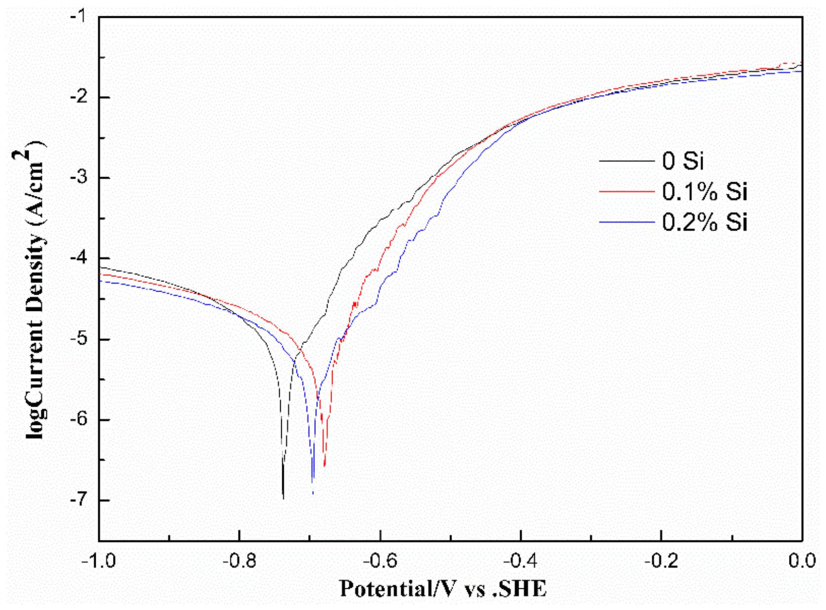
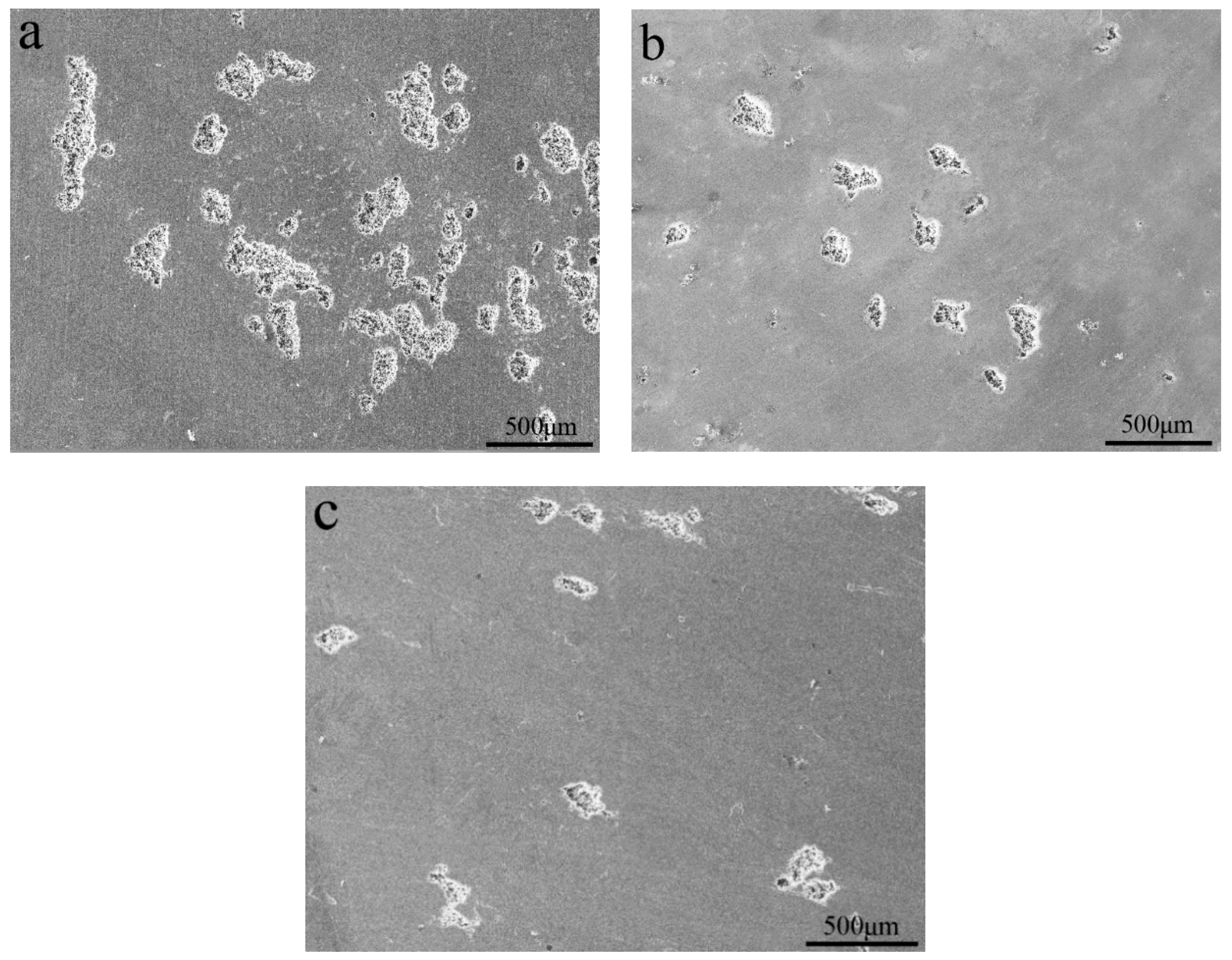
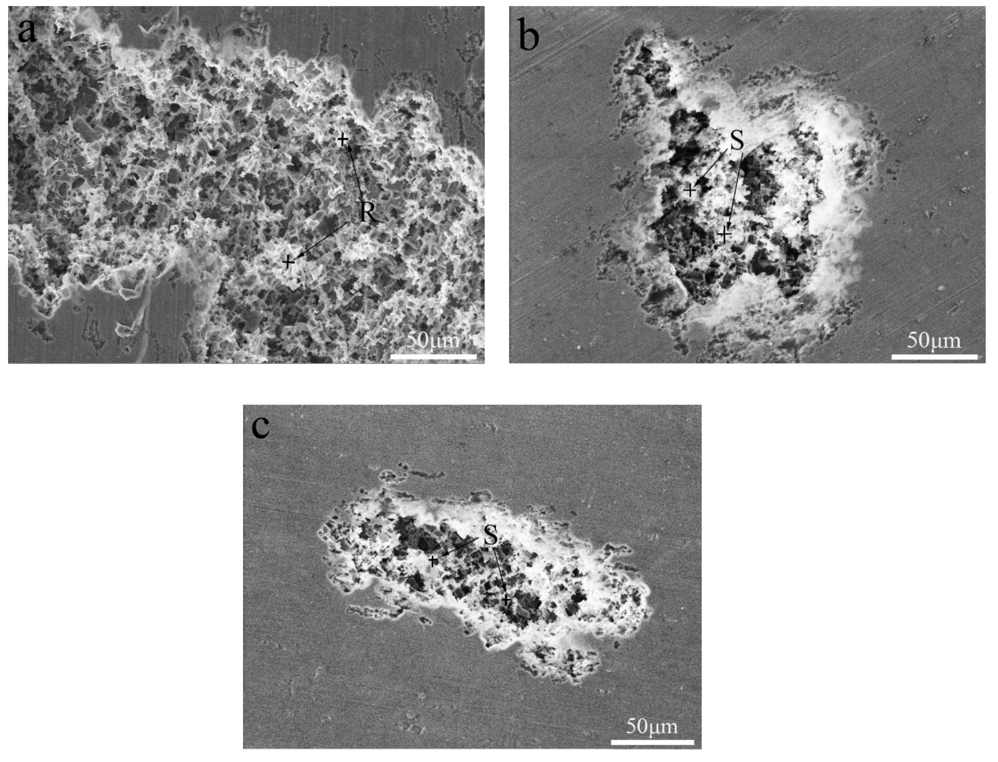
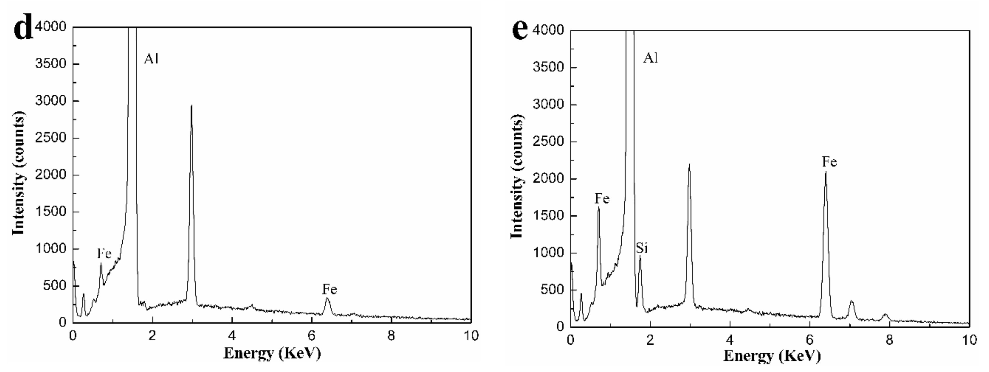
3.3. Electrochemical Performance

Figure 8 shows Tafel polarization curves of the three kinds of alloys tested in 3.5 wt.% NaCl solution. The corrosion potential ( E c o r r ) and corrosion current density ( I c o r r ) obtained by analyzing the Tafel polarization curve are shown in Table 2 [21]. The polarization curves of the three alloys exhibited similar shapes. A low corrosion potential implied that the alloy was more susceptible to corrosion and a high corrosion current density means faster alloy corrosion processes [22]. Combined with the results of Table 2, it can infer that, with the addition of the Si element, the Si-containing alloy had a higher corrosion potential and lower corrosion current density than that of the Si-free alloy. It was obvious that the addition of Si improved the corrosion resistance of the Al-Fe-Cu-La alloy.
The corrosion resistance of the present alloys depended on the passivation film and its ability to self-heal after the passivation film was broken. The destruction of the passivation film was likely to occur at the microdefects of the alloy. During the etching process, intermetallic particles resulted in the potential difference between the second phase particles and the α-Al matrix in the present alloys. When the alloys were exposed to a solution containing chloride ions, these second phase particles may have caused localized erosion and enhanced the sensitivity of the alloy to pitting. Figure 9 and Figure 10 present corrosion surface images of the alloys in 3.5 wt.% NaCl solution. It was obvious that the alloys corrosion was in the form of aluminum alloy pitting. Pits with similar morphology were observed on the surface of three alloys. Compared to the Si-containing alloy, Si-free alloy had more pits and the larger pitting area. This further confirmed that the corrosion resistance of the alloys improved with the addition of Si. Combined with EDS analysis, we can find that the residual substance in the pit was the Fe-containing phase (see the R and S regions of Figure 10) [23]. The presence of Fe-containing intermetallic compound particles adversely affected corrosion resistance, since the Fe-rich phase was the catalytic site for the cathodic reaction and the site for pit nucleation [24,25].
Since the corrosion potential between the Fe-containing intermetallic phase and the matrix was different, the etching pit preferably started at the location of the Fe-containing second phase particles. The Fe-containing particles of the local cathode enhance the cathodic reaction [11,26], resulting in local corrosion near the Fe-containing site. As a result, the α-Al matrix was preferentially dissolved in the vicinity of the Fe-containing second phase particles. The high Fe content of Al3Fe was advantageous for the cathodic reaction, typically oxygen reduction, which results in an increase of the local PH of the solution adjacent to the intermetallic particles. Local alkalization caused the Al matrix around the Al3Fe particles dissolved while the inclusions remain inert (Although in some cases, local dissolution of the matrix destroyed the particles, causing particles to be lost from the surface) [23]. The Al3Fe phase transition to the AlFeSi phase due to the addition of Si, which reduced the effect of Fe on the anode and cathode reaction rates [27]. Thus, the formation of AlFeSi phase may help to improve the corrosion performance of the Al-Fe-Cu-La alloy.

4. Conclusions

In this work, the effects of Si addition on the microstructure, mechanical properties and corrosion behavior of Al-Fe-Cu-La alloy were systematically studied. Grain size was strongly influenced by the addition of Si. The addition of Si resulted in the formation of AlFeSi particles and the AlFeSi phase nucleated and grew along the surface of the AlFeLa phase.
The addition of Si promoted the refinement of the grain in the Al-Fe-Cu-La alloy. Due to Si addition, the strength of the alloy in the temperature range of −20 °C to 50 °C was greatly improved and the high temperature stability of the alloy was also greatly enhanced. Meanwhile, the effect of Si addition on the alloy conductivity was acceptable. Compared with Si-free alloys, Si-containing alloys have more micrometer sized dimples on the fracture surface in the temperature range of −20 °C to 50 °C.
Smaller and fewer pits on the corroded surface were found with the Si-containing alloy. The addition of Si promoted the conversion of AlFe binary phase particles to AlFeSi ternary phase particles, which helped to improve the corrosion resistance of the alloy.
In view of this article, the addition of silicon to aluminum alloys greatly enhances their mechanical and electrochemical properties. The above studies do not fully explain the mechanism. The mechanism of improving properties by adding silicon needs further study.

Author Contributions

Conceptualization, D.D.; formal analysis, Y.G., G.C., Y.H., J.T., W.Z.; investigation, Y.X., Z.W., X.Y., and R.C.; writing—original draft preparation, Y.X.; writing—review and editing, Y.X. and D.D.; project administration, D.D.

Funding

This work was supported by the Shanghai Excellent Technical Leader Project (No. 15XD1524600).

Acknowledgments

The authors would like to thank the Instrumental Analysis Center of Shanghai Jiao Tong University for SEM experiments.

Conflicts of Interest

The authors declare no conflict of interest.

References

  1. Benites, N.R. Electrochemical performance of cathodes prepared on current collector with different surface morphologies. J. Power Sources 2013, 244, 532–537. [Google Scholar]
  2. Chen, Y.; Pan, Y.; Lu, T.; Tao, S.; Wu, J. Effects of combinative addition of lanthanum and boron on grain refinement of Al–Si casting alloys. Mater. Des. 2014, 64, 423–426. [Google Scholar] [CrossRef]
  3. Chang, J.Y.; Kim, G.H.; Moon, I.G.; Choi, C.S. Rare earth concentration in the primary Si crystal in rare earth added Al-21 wt.% Si alloy. Scr. Mater. 1998, 39, 307–314. [Google Scholar] [CrossRef]
  4. Chang, J.; Moon, I.; Choi, C. Refinement of cast microstructure of hypereutectic Al-Si alloys through the addition of rare earth metals. J. Mater. Sci. 1998, 33, 5015–5023. [Google Scholar] [CrossRef]
  5. Yao, D.; Xia, Y.; Qiu, F.; Jiang, Q. Effects of La addition on the elevated temperature properties of the casting Al–Cu alloy. Mater. Sci. Eng. A-Struct. Mater. Prop. 2011, 528, 1463–1466. [Google Scholar] [CrossRef]
  6. Yao, D.; Zhao, W.; Zhao, H.; Qiu, F.; Jiang, Q. High creep resistance behavior of the casting Al–Cu alloy modified by La. Scr. Mater. 2009, 61, 1153–1155. [Google Scholar] [CrossRef]
  7. Tsai, Y.C.; Chou, C.Y.; Lee, S.L.; Lin, C.K.; Lin, J.C.; Lim, S.W. Effect of trace La addition on the microstructures and mechanical properties of A356 (Al-7Si-0.35Mg) aluminum alloys. J. Alloys Compd. 2009, 487, 157–162. [Google Scholar] [CrossRef]
  8. Huang, X.; Yan, H. Effect of trace La addition on the microstructure and mechanical property of as-cast ADC12 Al-Alloy. J. Wuhan Univ. Technol. Mater. Sci. Ed. 2013, 28, 202–205. [Google Scholar] [CrossRef]
  9. Westphal, B.G.; Bockholt, H.; Günther, T.; Haselrieder, W.; Kwade, A. Influence of convective drying parameters on electrode performance and physical electrode properties. In Proceedings of the 226th Meeting of the Electrochemical Society, Cancun, Mexcio, 5–9 October 2014. [Google Scholar]
  10. Johnsson, M. Influence of Si and Fe on the grain refinement of aluminum. Z. Metallk. 1994, 85, 781–785. [Google Scholar]
  11. Ambat, R.; Davenport, A.J.; Scamans, G.M.; Afseth, A. Effect of iron-containing intermetallic particles on the corrosion behavior of aluminum. Corros. Sci. 2006, 48, 3455–3471. [Google Scholar] [CrossRef]
  12. Bakhteeva, N.D.; Todorova, E.V.; Kolobylina, N.N.; Vasil’ev, A.L.; Sirotinkin, V.P. Structure of polycrystalline Al-Ni-Fe-La alloys after quenching and plastic deformation by shear under pressure. Russ. Metall. 2013, 2013, 206–216. [Google Scholar] [CrossRef]
  13. Tai, C.; Nakata, K.; Tong, H.J.; Ushio, M. Dissimilarmetal joining of aluminum to steel by MIG arc brazing using flux cored wire. ISIJ Int. 2003, 43, 1596–1602. [Google Scholar]
  14. Song, J.L.; Lin, S.B.; Yang, C.L.; Ma, G.C.; Liu, H. Spreading behavior and microstructure characteristics of dissimilar metals TIG welding-brazing of aluminum alloy to stainless steel. Mater. Sci. Eng. A-Struct. Mater. Prop. Microstruct. Process. 2009, 509, 31–40. [Google Scholar] [CrossRef]
  15. Alexandre, M.; Simone, M.; Deschamps, A.; Martin, B.; Grevey, D. Temperature control in laser brazing of a steel/aluminum assembly using thermographinc measurments. NDT E Int. 2006, 39, 272–276. [Google Scholar]
  16. Boag, A.; Taylor, R.J.; Muster, T.H.; Goodman, N.; McCulloch, D.; Ryan, C.; Route, B.; Jamieson, D.; Hughes, A.E. Stable pit formation on AA2024-T3 in a NaCl environment. Corrosion Sci. 2010, 52, 90–103. [Google Scholar] [CrossRef]
  17. Tseng, C.J.; Lee, S.L.; Tsai, S.C.; Cheng, C.J. Effects of manganese on microstructure and mechanical properties of A206 alloys containing iron. J. Mater. Res. 2002, 17, 2243–2250. [Google Scholar] [CrossRef]
  18. Moreira, A.H.; Benedetti, A.V.; Sumodjo, P.T.A.; Garrido, J.A.; Cabot, P.L. Electrochemical behavior of heat-treated Al-Zn-Mg alloys in chloride solutions containing sulphate. Electrochim. Acta 2002, 47, 2823–2831. [Google Scholar] [CrossRef]
  19. Du, J.D.; Ding, D.Y.; Zhang, W.L.; Xu, Z.; Gao, Y.; Chen, G.; You, X.; Chen, R.; Huang, Y.; Tang, J. Effect of Ce addition on the microstructure and properties of Al-Cu-Mn-Mg-Fe lithium battery shell alloy. Mater. Charact. 2018, 142, 252–260. [Google Scholar] [CrossRef]
  20. Han, L.; Sui, Y.; Wang, Q.; Wang, K.; Jang, Y. Effects of Nd on microstructure and mechanical properties of cast Al–Si–Cu–Ni–Mg piston alloys. J. Alloys Compd. 2016, 695, 1566–1572. [Google Scholar] [CrossRef]
  21. Thiede, V.M.T.; Ebel, T.; Jeitschko, W. Ternary aluminides LnT2Al10 (Ln = Y, La–Nd, Sm, Gd–Lu and T = Fe, Ru, Os) with YbFe2Al10 type structure and magnetic properties of the iron-containing series. J. Mater. Chem. 1998, 8, 125–130. [Google Scholar] [CrossRef]
  22. Chai, Z.; Jiang, C.; Zhu, K.; Zhao, Y.; Wang, C.; Cai, F.; Chen, M.; Wang, L. Pretreatment behaviors and improved corrosion resistance for Cu/Co-Ni-Cu coating electrodeposition on magnesium alloy. J. Electrochem. Soc. 2016, 163, D493–D499. [Google Scholar] [CrossRef]
  23. Rynders, R.M.; Paik, C.H.; Ke, R.; Alkire, R.C. Use of in situ atomic force microscopy to image corrosion at inclusions. J. Electrochem. Soc. 1994, 141, 1439–1445. [Google Scholar] [CrossRef]
  24. Zahavi, J.; Yahalom, J. Exfoliation corrosion of AlMgSi alloys in water. J. Electrochem. Soc. 1982, 129, 1181–1185. [Google Scholar] [CrossRef]
  25. Mattsson, E.; Gullman, L.O.; Knutsson, L.; Sundberg, R.; Thundal, B. Mechanism of exfoliation (layer corrosion) of AI-5%Zn-1%Mg. Br. Corros. J. 1971, 6, 73–83. [Google Scholar] [CrossRef]
  26. Speckert, L.; Burstein, G.T. Combined anodic/cathodic transient currents within nucleating pits on Al–Fe alloy surfaces. Corros. Sci. 2011, 53, 534–539. [Google Scholar] [CrossRef]
  27. Nis, K. Electrochemical behavior of aluminum-base intermetallics containing iron. J. Electrochem. Soc. 1990, 137, 69–77. [Google Scholar]
Figure 1. Longitudinal section microstructure of the Al-0.25Fe-0.1Cu-0.1La alloy with different Si contents: (a) 0 wt.%; (b) 0.1 wt.%; (c) 0.2 wt.%.
Metals 09 01072 g001
Figure 2. X-ray diffraction (XRD) patterns of the Al-0.25Fe-0.1Cu-0.1La alloys with and without Si addition.
Metals 09 01072 g002
Figure 3. The backscattered scanning electron microscopy (SEM) images and energy dispersive X-ray spectroscopy (EDS) patterns of the Al-0.25Fe-0.1Cu-0.1La alloys with different Si content: (a),(b) 0 wt.%; (c),(d) 0.1 wt.%; (e),(f) 0.2 wt.%. (b,d,f) depict the EDS patterns of AlFeCu phase (M), AlFeLa phase (N) and AlFeSi phase (O), respectively.
Metals 09 01072 g003aMetals 09 01072 g003b
Figure 4. SEM image and EDS mapping of Al, Fe, Cu, La, Si elements for Al-0.25Fe-0.1Cu-0.1La-0.1Si alloy.
Metals 09 01072 g004
Figure 5. Room temperature tensile fracture of the Al-0.25Fe-0.1Cu-0.1La alloys with different Si contents: (a) 0 wt.%; (b) 0.1 wt.%; (c) 0.2 wt.%, (d) and (e) are EDS pattern of the AlFeCu particle (P), AlFeSi particle (Q).
Metals 09 01072 g005
Figure 6. Tensile fracture of the Si-free alloy tested at (a) –20 °C, (b) 25 °C and (c) 50 °C.
Metals 09 01072 g006
Figure 7. Tensile fracture of the 0.1 wt.% Si-containing alloy tested at (a) −20 °C, (b) 25 °C and (c) 50 °C.
Metals 09 01072 g007
Figure 8. Potentiodynamic polarization curves of the alloys tested in the 3.5 wt.% NaCl solution.
Metals 09 01072 g008
Figure 9. Corrosion surface morphology of the Al-0.25Fe-0.1Cu-0.1La alloys with different Si contents: (a) 0 wt.%; (b) 0.1 wt.%; (c) 0.2 wt.%.
Metals 09 01072 g009
Figure 10. Corrosion surface morphology of the Al-0.25Fe-0.1Cu-0.1La alloys with different Si contents: (a) 0 wt.%, (b) 0.1 wt.%, (c) 0.2 wt.%, (d) EDS pattern of AlFe particle at R region, and (e) EDS pattern of AlFeSi particle at S region.
Metals 09 01072 g010aMetals 09 01072 g010b
Table 1. Mechanical properties of the alloys tested at −20 °C, 25 °C and 50 °C.
TemperatureAlloyσ0.2 (MPa)σb (MPa)δ (%)
BaseSi Addition
−20 °CAl-0.25Fe-0.1Cu-0.1La0141.0154.82.34
0.1169.7184.11.43
0.2160.7175.41.51
25 °CAl-0.25Fe-0.1Cu-0.1La0129.7141.92.50
0.1169.0175.31.54
0.2160.3168.71.63
50 °CAl-0.25Fe-0.1Cu-0.1La0104.6132.02.50
0.1148.1163.41.66
0.2139.5155.31.88
Table 2. Potentiodynamic polarization curves parameters of the alloys tested in 3.5 wt.% NaCl solution.
Alloy E c o r r (mV vs. SCE) I c o r r (10−6 A/cm2)
BaseSi Addition
Al-0.25Fe-0.1Cu-0.1La0−7396.376
0.1−6795.414
0.2−6955.615

