Article

Influence of Tempering Time on the Behavior of Large Carbides’ Coarsening in AISI H13 Steel

1
College of Materials Science and Engineering, Taiyuan University of Technology, Taiyuan 030024, China
2
Department of Mining and Materials Engineering, McGill University, 3610 University St., Montreal, QC H3A 0C5, Canada
3
Central Iron and Steel Research Institute, Beijing 100081, China
4
School of Metallurgical and Ecological Engineering, University of Science and Technology Beijing, Beijing 100083, China
*
Author to whom correspondence should be addressed.
Metals 2019, 9(12), 1283; https://doi.org/10.3390/met9121283
Submission received: 27 October 2019 / Revised: 25 November 2019 / Accepted: 27 November 2019 / Published: 29 November 2019
(This article belongs to the Special Issue Strengthening Mechanisms in Metallic Materials)

Abstract

:
The mechanical properties, microstructures and precipitation behaviors in AISI (American Iron and Steel Institute) H13 steel tempered at 863 K for 0.5, 2, 4, 10 and 20 h were investigated. The values for H13 tempered for 2–4 h resulted in die steel that reached the desired properties as specified in NADCA (North American Die Casting Association) #207-2016. The cubic Ostwald ripening model was applied to simulate the coarsening of the large carbides, which were mainly M23C6 and M3C, as determined from FactSage predictions as well as measurements with transmission electron microscopy (TEM). TEM revealed that the equivalent circle radius (ECR) decreased during 0.5–2 h, because of the nucleation of many new precipitates. According to the Ashby-Orowan modified precipitation strengthening model, this decrease in ECR leads to an increase in the contribution of precipitates to yield strength. Between 2 and 4 h tempering, the ECR of large carbides increases sharply but then increases asymptotically from 4 to 20 h, which obeys the calculated Ostwald ripening rate for cementite and M23C6 in H13 after 863 K tempering. This observation for the Ostwald ripening of M23C6 is in agreement with experimental data for other steels in the literature.

1. Introduction

In hot metal forming operations, the life of hot work dies is restricted due to the extreme working conditions in terms of thermal and mechanical loading [1]. The AISI designated H13 steel (4Cr5MoSiV1), as a quench and tempered steel, which has high hardenability, strength, toughness and softening resistance, can be widely applied as a material for hot work dies [2]. However, the heterogeneous distribution of alloying elements, including carbon, affects the mechanical properties of H13, especially its high temperature stability [2,3].
Researchers have improved the strength and toughness of H13 by adding elements such as rare earths [3], niobium [4] and/or nitrogen [5], as well as altering preheat treatment process [6] (austenitizing temperature and cooling rate) or adding pre-tempering steps [7]. All the above methods indicate that the secondary precipitates (<300 nm) [7] are the main contributor to the strength and toughness of H13.
Meanwhile, carbide coarsening, especially M23C6 coarsening, was mainly reported in low Cr steel [8], P91, P92 series [9,10,11] and high Cr steels [12,13,14,15]. As is known, large particles such as eutectic carbides and secondary carbides have lost the function of preventing grain coarsening, providing both nucleation sites and propagation paths of cracks [16]. It can be seen that the coarsening of M23C6 always exists in medium or high Cr alloyed steels, including H13.
According to the previous work on H13, the precipitates after tempering were mainly composed of V8C7, M23C6, M6C and M2C [17,18]. Delagnes [19] also reported that M3C existed in H13 steel. Precipitation strengthening of H13 has been investigated [18,20]. Meanwhile, the coarsening of carbides was investigated by Hu [21] through experiments and model simulations. He subjected the H13 to austenitizing at 1298 K for 30 min, quenching, and then tempering twice at 883 K for 2 h, and then ageing at 973 K for 20–240 min to coarsen the M23C6. He simulated the coarsening rate of M23C6 during ageing by deploying DICTRA in Thermocalc. The result showed the value of simulation was lower than the experimental result but within an order of magnitude.
In this article, the hardness, strength and impact toughness values after different tempering times for an AISI H13 steel are investigated. The precipitation size and distribution of each state are measured and their contributions to yield strength are calculated by the Ashby-Orowan modified model. The Ostwald ripening model for this alloy is evaluated and is used to compare with the experimental data in the literature.

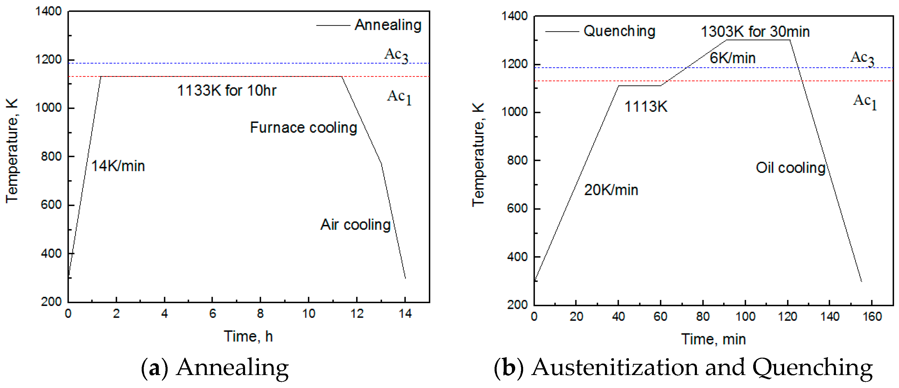
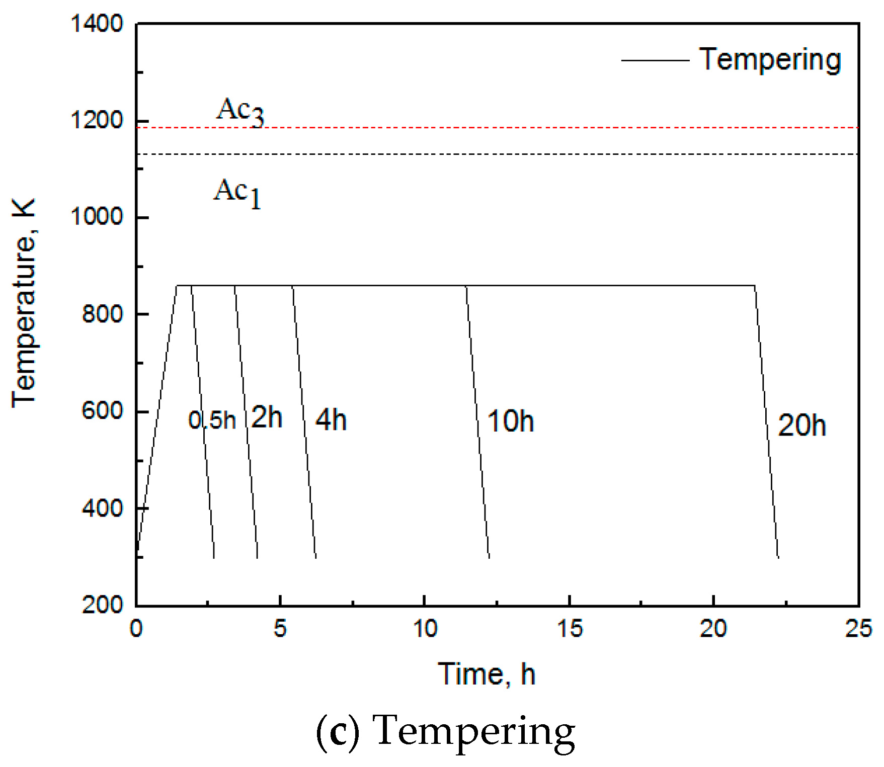
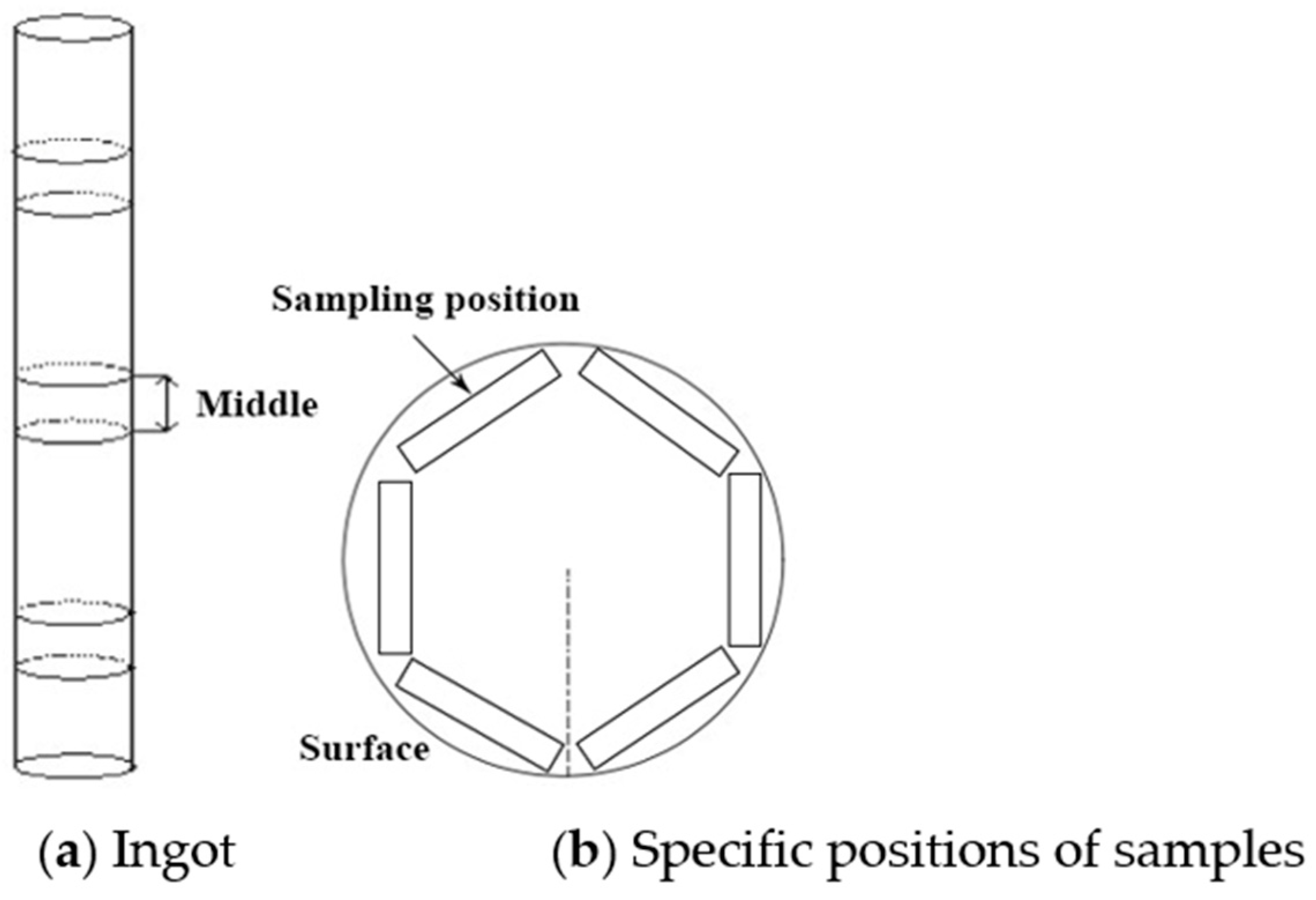
2. Experimental Materials and Methods

The chemical composition of H13, which was obtained from the Central Iron and Steel Research Institute (CISRI, Beijing, China), is shown in Table 1. The Ac1 temperature (phase transformation γ → α) of this steel is within the range of 1133 K (Ac1) and 1188 K (Ac3) [22]. The ingot was forged at 1373 K to bar stock with a diameter of 105 mm. According to CISRI industry practice, the forged ingot was annealed at 1133 K for 10 h, cooled to 773 K in the furnace, and further cooled to room temperature in air, as shown in Figure 1a. The objective of annealing is to relieve the stress due to forging in order to reduce the risk of cracking, and to reduce the hardness of steel in order to increase its toughness and ductility. Some of the alloy carbides are undissolved to prevent the grain coarsening during annealing [23]. The microstructure after annealing is composed of pearlite and spherical carbides [24].
A 60 mm thick sample was cut from the middle of the annealed ingot, as shown in Figure 2a. This sample was preheated to 1113 K at a rate of 20 K/min, held for 20 min, then heated to 1303 K at a rate of 6 K/min, held for an additional 30 min, and then quenched in oil at a quench rate of approximately 33 K/min, as shown in Figure 1b.
Six samples were cut near the surface of the quenched specimen, as shown in Figure 2b. One was left as-quenched. The others were tempered for 0.5 h, 2 h, 4 h, 10 h and 20 h at 863 K, respectively, and then cooled in air to room temperature, as shown in Figure 1c.
Smaller samples were then cut from the main samples for transverse impact value (Charpy V-notch) tests, tensile measurements and metallographic studies. The dimensions of the Charpy test samples was 10 × 10 × 55 mm3; the tensile test samples were φ8 × 50 mm (fillet radius is 6 mm and gripping end is φ12 × 25 mm), and the metallographic samples were 10 × 10 × 10 mm3. The electrolysis sample for precipitate extraction was φ10 mm × 80 mm and there was a φ2 mm hole at one end of each sample for bolting copper wire.
The impact values of the six samples were tested by a ZBC2452-B Pendulum impact testing machine (MTS System Corporation, Shenzhen, China). Tensile strength and yield strength were measured with a CMT4105 electronic universal testing machine (MTS System Corporation, Shenzhen, China). A 500MRA Rockwell hardness tester was used to measure the hardness of the samples. The microstructure of the steel was observed with a 9XB-PC optical microscope (Shanghai Optical Instrument Factory, Shanghai, China). Precipitates were extracted by electrolysis using an electrolyte of 1% tetramethylammonium chloride and 10% acetone in methanol solution. The current density I = 0.04–0.06 A/cm2. After electrolysis, residues were collected, cleaned with water and dried. The phase compositions of collected powders were identified by X-ray diffraction (XRD) (RIGAKU, Tokyo, Japan) with a Cu-Kα characteristic radiation source in the 2θ range of 20–120°. Microstructure of H13 was observed by optic microscopy (Clemex-Nikon system, Tokyo, Japan) and scanning electron microscopy (HITACHI SU3500, Tokyo, Japan) installed with energy dispersive spectrometer (EDS). The morphology and distribution of carbides in the five samples was examined using carbon extraction replicas with an F30 high resolution transmission electron microscope (HR TEM) (FEI Company, Hillsboro, OR, USA). The carbon replicas were prepared by depositing a 20–30 nm thickness carbon film on the sample surface etched with 8% nital after polishing. The carbon films were removed with 10% nital and supported on copper mesh [25]. Thermodynamic calculations were carried out by using FactSage 7.2 software which was based on FSstel database for steels. This software is produced by Thermfact (Montreal, QC Canada) and GTT-Technology (Aachen, Germany).

3. Experimental Results

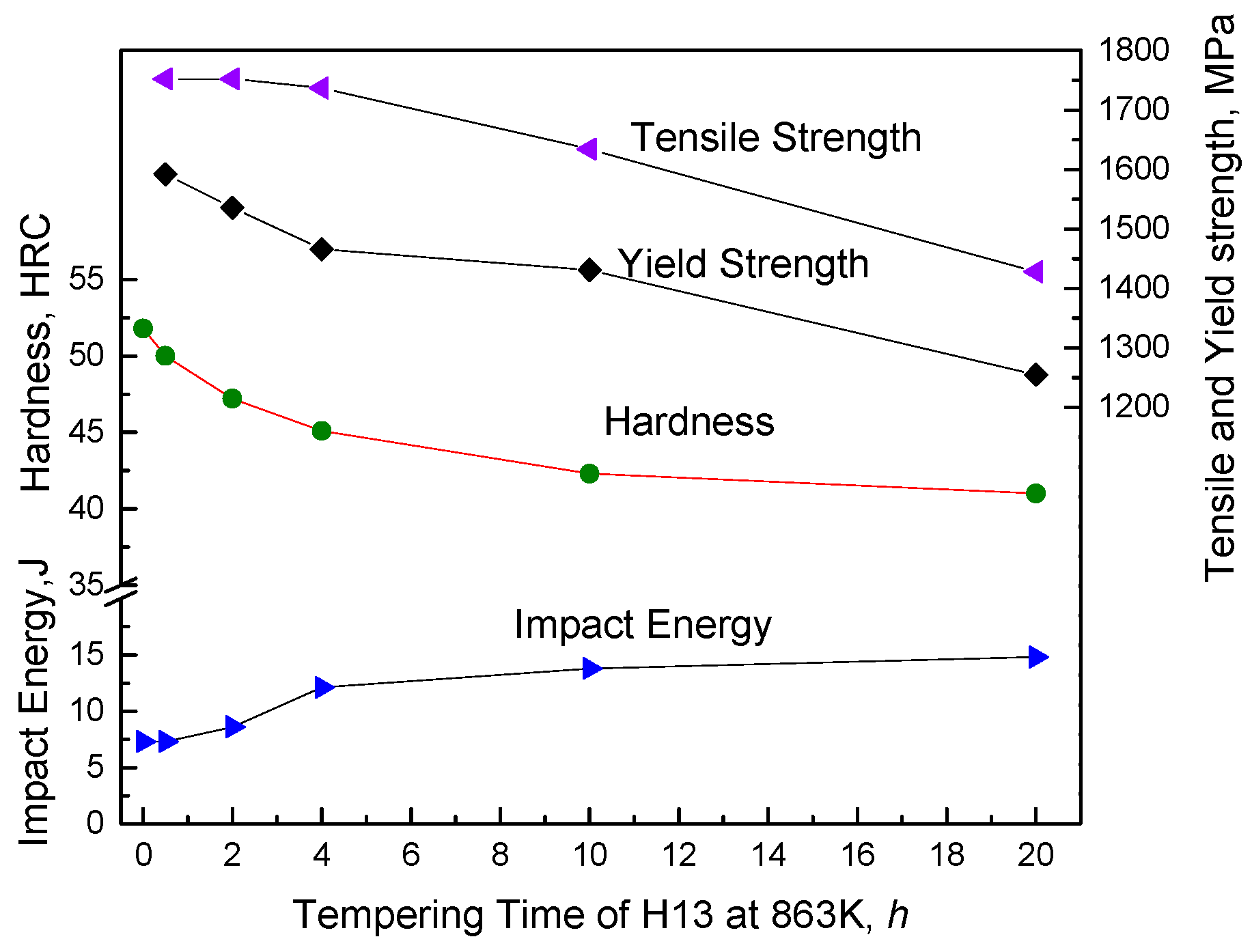
3.1. Mechanical Properties of H13
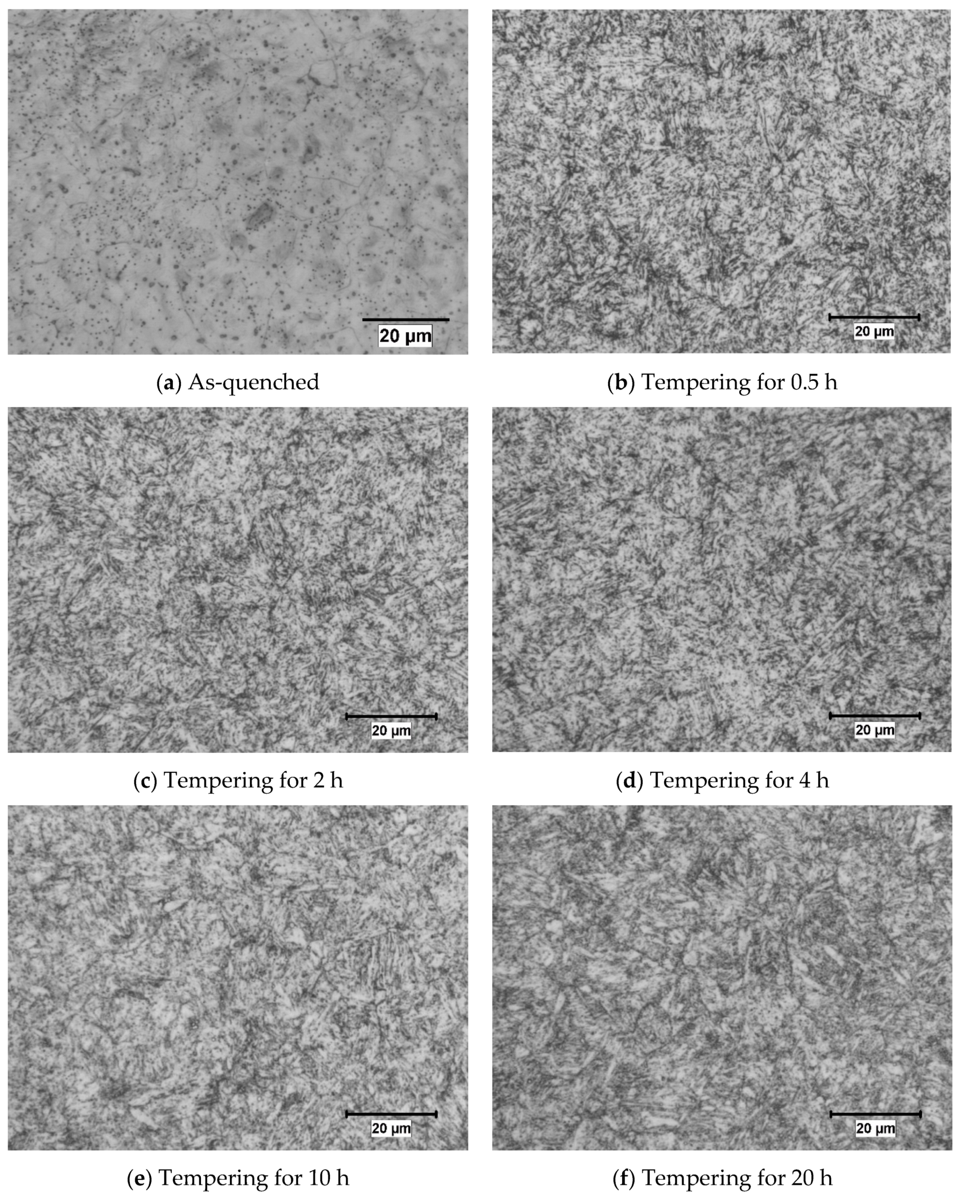
The mechanical properties of the as-quenched and as-tempered specimens are illustrated in Figure 3.
As expected, the as-quenched H13 have highest hardness and strength but the lowest impact toughness. Hardness and strength decrease, and the toughness increases with tempering time increases. Figure 3 also indicates that the sample tempered for 2–4 h basically meets the desired properties set by NADCA#207-2016 (i.e., 44–46HRC and an average impact value > 10.9 J with its lower limit at 8.1 J). During tempering, the precipitates hinder the movement of dislocations, so that the strength and hardness do not decrease very sharply as tempering time increases [26].

3.2. Microstructure

The optical microstructures of the tempered steels are shown in Figure 4. The steels have been etched by 4% nital. The as-quenched microstructure does not reveal much detail (Figure 4a) and no significant effects of time on the steel microstructure are revealed after tempering (Figure 4b–f). Of course, the above mentioned important microstructural changes cannot be resolved using optical microscopy.
As is well known, during tempering, martensite decomposes into α phase and dispersed carbides, which decreases the strength and hardness and increases the toughness. As the tempering time increases, recovery of lath martensite takes place in which dislocation density reduces and forms subgrains [26]. The product of retained austenite decomposition, depending on steel composition, can be ferrite and carbides, martensite or bainite, which affect the mechanical properties [27,28]. On the other hand, retained austenite transforms to tempered martensite (i.e., α and carbides).
Using SEM with BSE (back scatter electron) mode on nital etched specimens, martensite laths are revealed, as shown in Figure 5, although it is still difficult to resolve them in the as-quenched condition (Figure 5a). However, relatively large precipitates can be seen in the as-quenched condition; EDS analysis (Figure 5c) reveals these to be V bearing. After tempering, there are more and finer carbides as shown in Figure 5b after 20 h treatment.

3.3. Effect of Precipitates on Mechanical Properties

The mechanical properties are influenced by many microstructural changes during tempering. The rest of the paper will focus on precipitation to indicate the contribution of changes in precipitate characteristics on the mechanical properties.

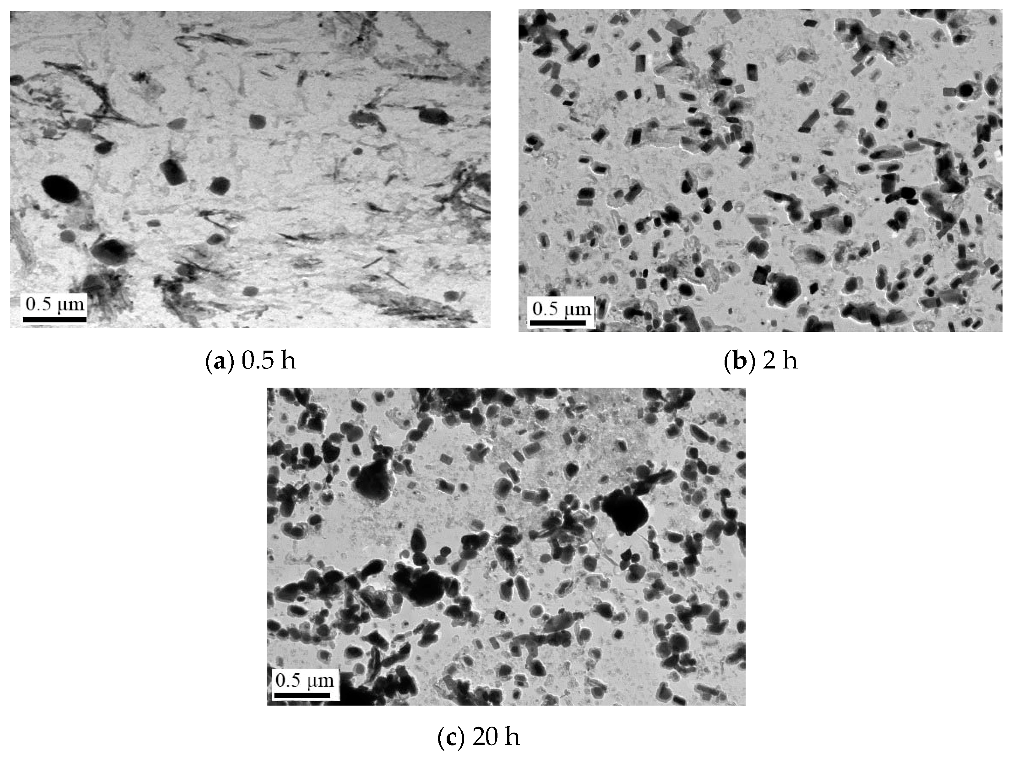
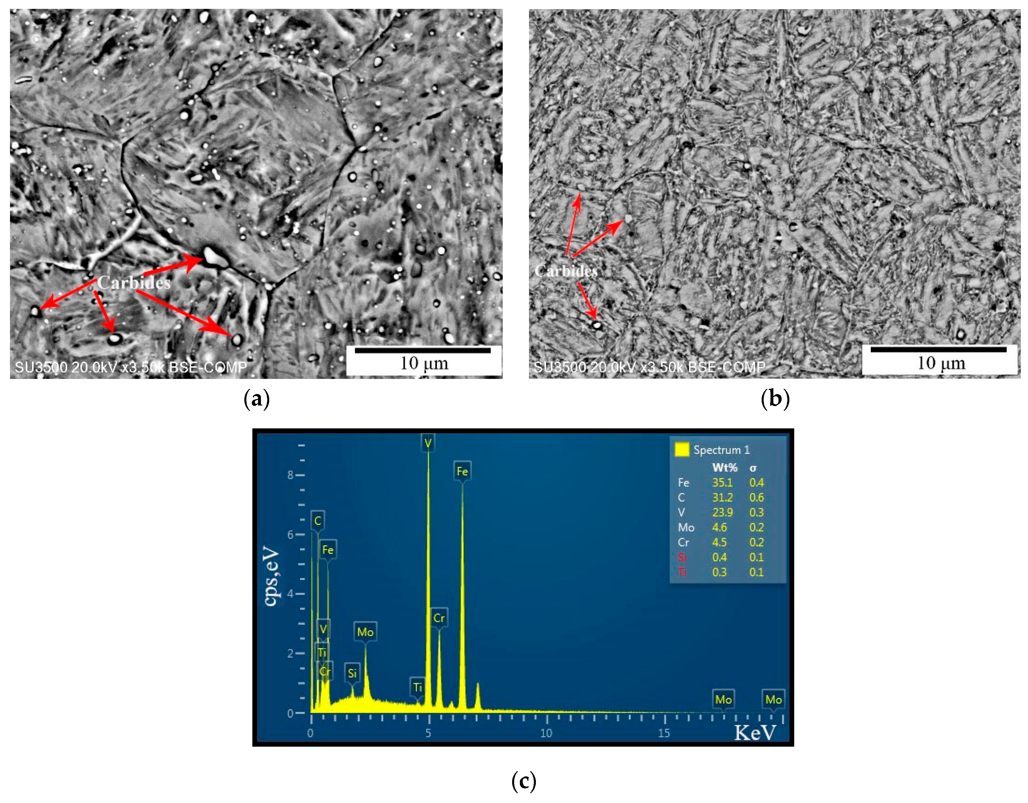
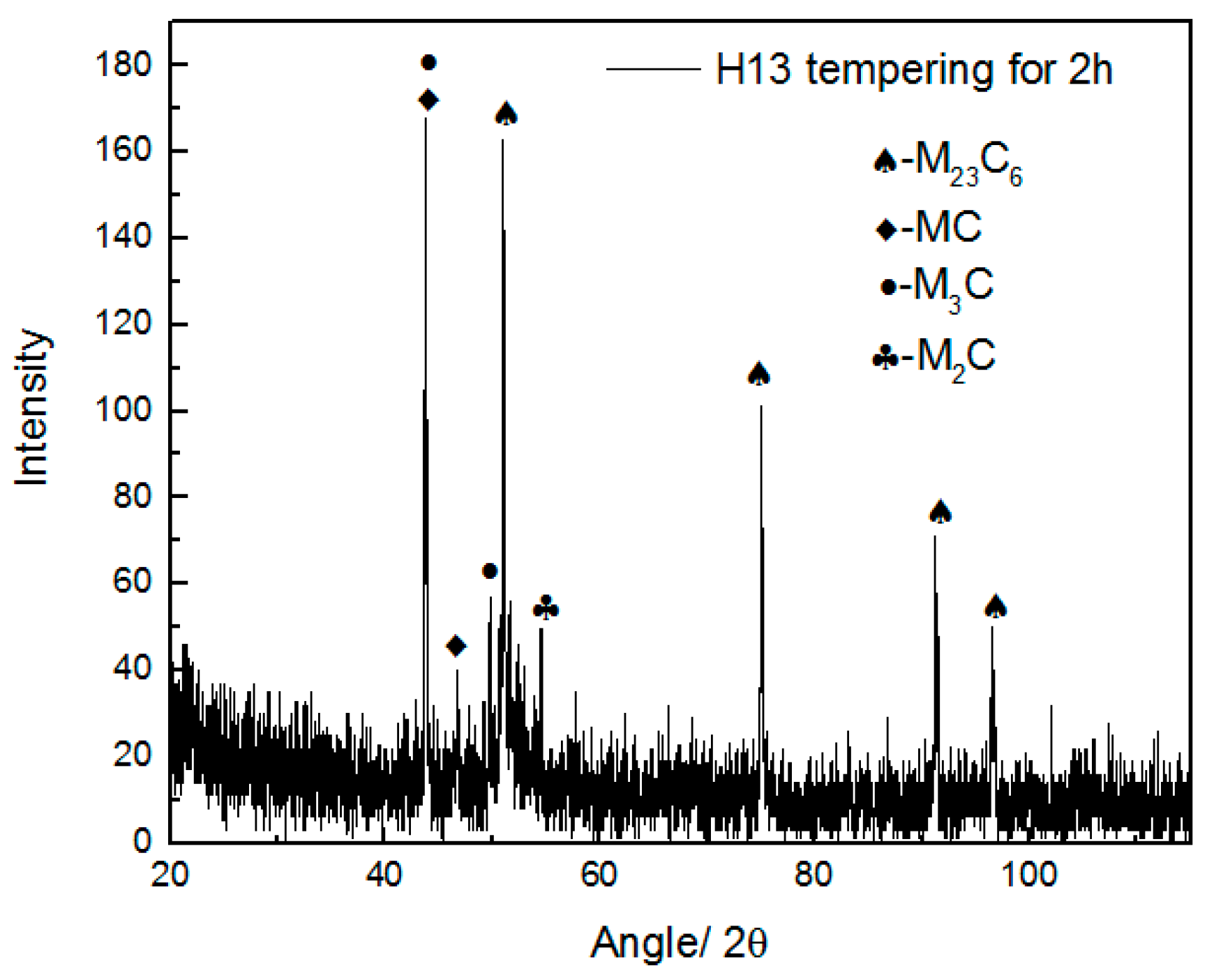
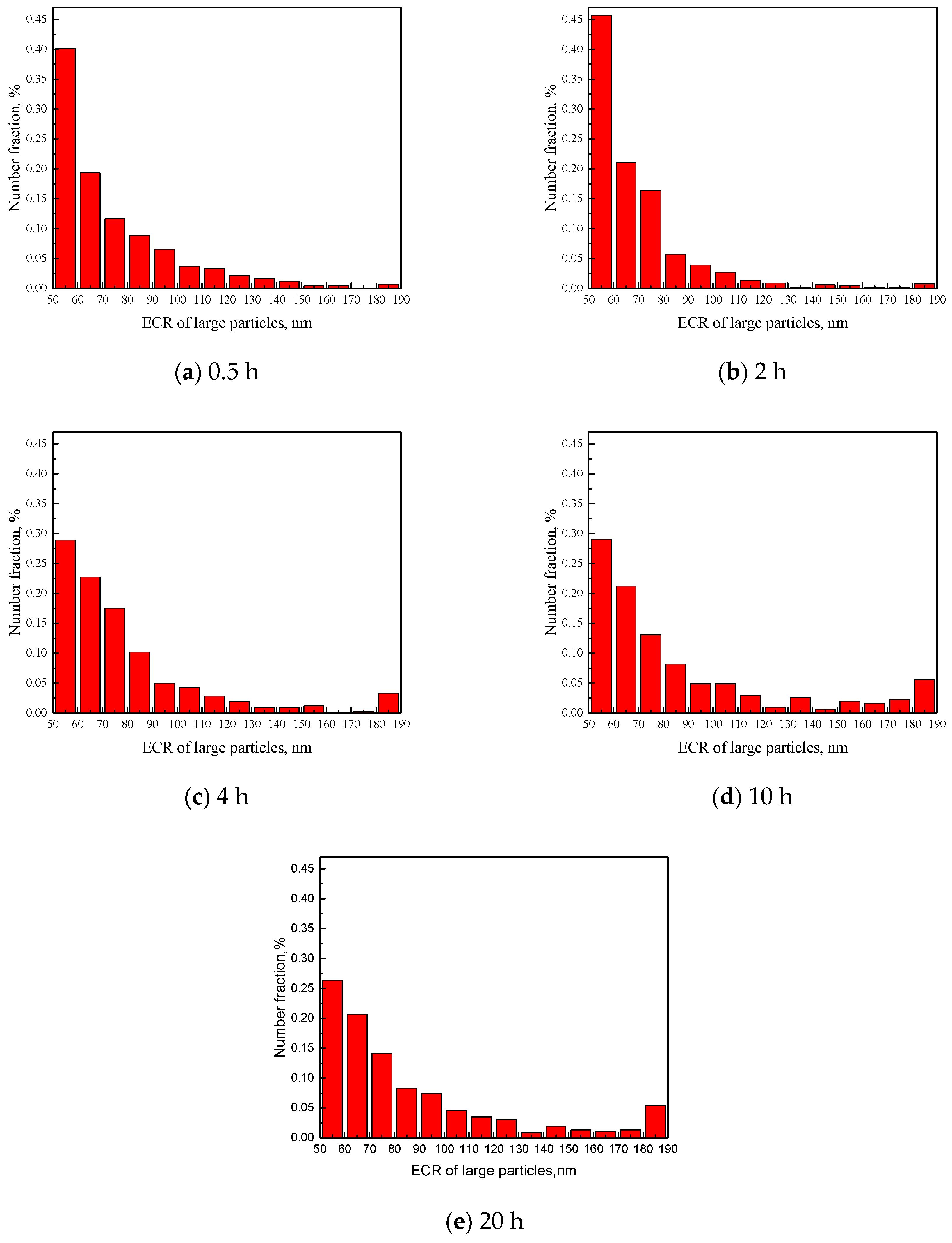
3.3.1. Types, Size and Volume Fraction of Large Carbides in H13 after 863 K Tempering

In our previous work using TEM, the precipitates in H13 after tempering mainly include M23C6, M6C and VC [17,20]. In order to detect whether there are other types of carbides in H13, the specimen tempered for 2 h was chosen for the electrolysis experiment. The collected powder was then analyzed by XRD. The result is shown as Figure 6. Precipitates in H13 after tempering are identified as hexagonal Mo-based M2C, face-centered cubic MC, body-centered cubic M23C6, and orthorhombic M3C.
After semi quantitative analysis of the XRD spectrum, M23C6 is composed of Mo, Mn and Cr, the amount of which is 80.1 wt% of the powder, MC is composed of V and Mo, and takes up 9.2 wt% of the powder, M2C is mainly Mo2C, which is a trace amount, and finally there is a significant amount of M3C (9.3 wt%), i.e., cementite (Fe3C). All of these precipitates were found in the above mentioned TEM studies, although Fe3C was not reported [17,18,21].
Figure 7a–c, which show TEM carbon replicas of typical precipitates after 0.5 h, 2 h and 20 h tempering, reveal that the precipitates increase in number and volume fraction with tempering time. The particle size distributions, in terms of the equivalent circle radius (ECR) of all five tempering times (from 0.5 to 20 h) are shown in Figure 8. These distributions are for particles of 50 nm and higher.
After observing hundreds of carbides in these five samples, it can be seen that the carbides which are around or below 50 nm in radius are mainly MC and M2C. Most of M23C6 and M3C are above 50 nm in radius. This experiment result is in accord with our published work [17]. In this experiment, we choose carbides above 55 nm in radius to exclude MC and M2C. Since it is difficult to distinguish M23C6 and M3C by shape and size, both of these are included in the precipitate analysis.
It can be seen that there is an increase in the numbers of 50–60 nm precipitates during 0.5–2 h tempering as shown in Figure 8a,b. These are most likely new precipitates forming as the martensite decomposes. As the tempering time increases, small particles begin to shrink and large particles grow, as shown in Figure 9b–e, which is characteristic of Ostwald ripening [29,30].

3.3.2. Calculation of Precipitation Strengthening

According to the method of McCall-Boyd [31] and the modified Ashby-Orowan model [32], the equations for the volume % (fi) of particles of a specific range, i, and precipitation strengthening, σ P , are respectively shown in Equations (1) and (2), below:
f i = ( 2.8 π 3 ) ( N i r i 2 A )
σ P = i = 1 n σ i = i n [ 10   μ b 5.72 π 3 / 2 r i f i 1 2 ln ( r i b ) ]
where A represents the area of the photos in μm2; Ni represents the number of precipitates within a certain range, i; ri represents the average radius in nm; μ is the shear modulus (80.65 × 10 3 MPa for steel [33]); and b is Burgers vector (2.48 × 10⁻⁴ μm) [33]. According to Equation (2), precipitation strengthening due to each size range is calculated and the total precipitation strengthening is a summation of all of these size range effects. In this analysis, approximately 150 TEM images (10 μm2 for each field) were used for these five samples. The results of the TEM characterization and calculations by Equations (1) and (2) are listed in Table 2 and Table 3.
Most large carbides (>55 nm in radius) in TEM observation are irregular spherical shaped. Here, ECR is also the corrected mean radius (nm). The given errors are estimates of 95% confidence interval of the expectation of the particle radius: r ± k 1 s , where s is the standard deviation and k 1 = 1.96 n [34].
From Table 3 all indications are that precipitation is completed between 0.5 and 2 h, since in this period the measured numbers and the volume % of precipitates both increase significantly, leading to a decrease in the ECR. Between 2 and 4 h, the ECR and volume % increase, which are indicative of Oswald ripening. Between 4 and 10 h, the ECR increases at a lower rate, but the volume % decreases; the latter is associated with the much lower numbers of precipitates observed, which is probably due to a sampling artefact. In fact, at 20 h, the volume % is the more or less the same as for 4 h, so it can be assumed that the volume % does not change between 4 and 20 h. Thus, because the volume % remains the same, Ostwald ripening leads to a decrease in the contribution to strength of these precipitates.

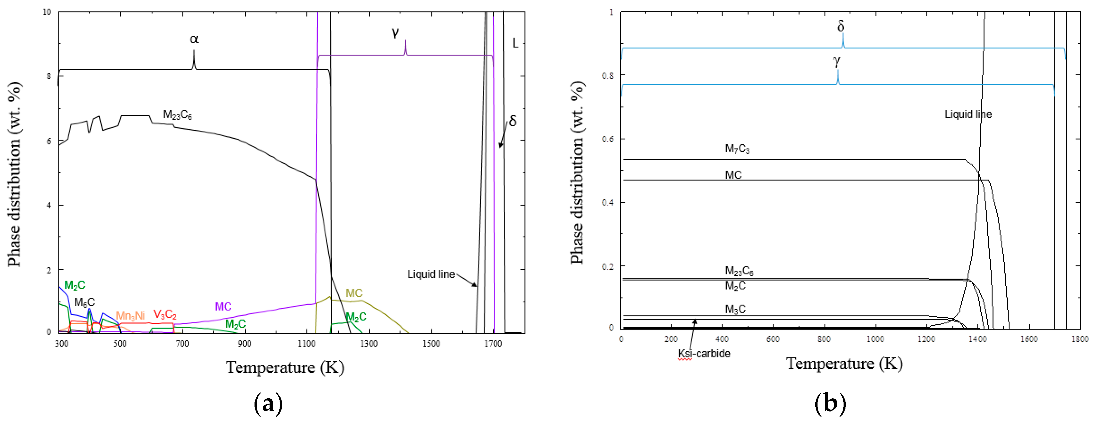
4. Calculation of Thermodynamic and Coarsening Kinetics of Precipitates in H13

The phase diagrams shown in Figure 9 were determined with the aid of FactSage based on the chemical compositions listed in Table 1. Figure 9a shows the equilibrium prediction. At the tempering temperature of 863 K, main precipitate is M23C6, which contains Fe, Cr, Mo and C and is 6.06 wt% of the matrix. In addition, MC mainly contains V and M2C mainly contains Mo. The calculated precipitation types correspond well with the experimental results.
To account for continuous cooling during processing, the Scheil-Gulliver Model is to calculate the alternative phase diagram shown in Figure 9b. Precipitation types are basically in accord with the observations of the experiments except M7C3. In fact, M7C3 tends to aggregate and combine with Fe to form M23C6 when the steel is tempered for a long time [22]. It can be seen that cementite and Ksi-carbides also precipitate and they exist stably in a temperature range of 500 K–1100 K. However, cementite is more stable than Ksi-carbides in high temperature tempering [26]. The mass fraction of cementite is about 0.041 wt%.
The precipitate coarsening model presented by Lifshitz et al. [29] and Wagner et al. [30] are known collectively as the LSW model. The principal assumptions in the LSW model are (i) the volume fraction of the precipitate is very low so that the diffusion fields of the neighboring precipitates do not overlap; (ii) the precipitates are spherical; and (iii) no elastic strains exist between the matrix and the precipitate.
The general formula of Ostwald ripening can be expressed as follows [29],
r t ¯ 3 = r 0 ¯ 3 + m 3 t
where r t ¯ is the average radius of precipitated phase at time t; r 0 ¯ is initial radius of precipitated phase; m is the coarsening rate of precipitated phase during Ostwald ripening process.
It is commonly recognized that coarsening rate of carbides is proportional to the mole fraction of rate-controlling element [35,36]. For M3C, it is carbon. However, other elements like Cr, Mn and V will influence the coarsening rate, because they have lower diffusion coefficient than carbon. For M23C6, it is Cr. But Mo and Mn will influence the coarsening rate, too.
Bjorklund [37] reported that when r reaches large values, slow diffusing substitutional alloying elements control the coarsening rate. The rate constant will then be proportional to the quantity ( 1 k i ) 2 , where k i is the partition coefficient of species i between the precipitates (β) and the matrix phase (α), k i = x i β x i α . Where, x i β is mole fraction of species i in precipitate, and x i α is mole fraction of species i in ferrite.
Thus, an accurate coarsening rate can be established as follows [38,39,40],
m 3 = 8 σ V P 9 R T i ( x i α ( 1 k i ) 2 D i ) 1
In Equation (4), σ is surface energy between alloy compounds and ferrite, J/m2; Vp is molar volume of precipitated phases, m3/mol; Di is the diffusion coefficient of species i in ferrite, m2/s; T is thermodynamic temperature, K; R is gas constant; therefore, the unit of m is nm / s 1 3 .
In a generalized multicomponent alloy system, such as H13 steel, the overall coarsening rate constant m results from the consideration of various solute additions. It can be also expressed as follows in Equation (5),
1 m 3 = i 1 m i 3
where m i is coarsening rate due to each alloying element. Faranak et al. [41] deployed this model to predict the coarsening of cementite in medium carbon steels. M23C6 coarsening was also estimated by this model [10].
The diffusion coefficients of the relevant elements are listed as follows [42]
D C α = 6.2 × 10 3 exp ( 80000 R T )
D Cr α = 8.52 exp ( 251000 R T )
D V α = 3.92 exp ( 241000 R T )
D Mo α = 1.3 exp ( 229000 R T )
D Mn α = 0.35 exp ( 220000 R T )
D W α = 2.0 exp ( 246000 R T )
The interfacial energy formula between cementite and ferrite [42] is also given as Equation (12).
σ ¯ Fe 3 C α = 1.0720 0.7161 × 10 3 T
Mole volumes of M3C and M23C6 in ferrite are 2.337 × 10⁻⁵ m3/mol and 0.79 × 10⁻⁵ m3/mol, respectively [42].
From the FactSage predictions, the mole fractions of Mo, V, Mn and Cr dissolved in ferrite and precipitates can be calculated, so that the partition coefficient of alloy elements can be determined. The coarsening results of large carbides in H13 in 863 K and 973 K are listed in Table 4 and Table 5.
In Table 4, the interfacial energy between M23C6 and ferrite is taken as 0.5 J/m2 both in 863 K and 973 K.
Coarsening of M3C is controlled by diffusion of carbon in ferrite. And carbon diffusion is influenced by other alloy elements in H13 such as Cr, Mn, V and Mo. Solubilities and diffusivities of alloy elements are shown in Table 5. The interfacial energy between M3C and ferrite is calculated according to Equation (12), and the results are 0.45 J/m2 and 0.38 J/m2.
It can be concluded that both M23C6 and M3C grow fast when the temperature rises from 863 K to 973 K, and m values for M3C are much larger than M23C6 at the same temperature.
Simulation and experiment results in H13 with tempering time at 863 K are compared in Figure 10a.
The experimental data are fitted by deploying Equation (3), and initial radius r 0 ¯ is set as 73.5 nm. The result is m = 1.78 nm / s 1 3 ; it is between the M3C (2.09 nm / s 1 3 ) and M23C6 (0.38 nm / s 1 3 ) coarsening rates.
As a rule of thumb, the interfacial energy of M23C6 varies between 0.1 and 1 J /m2 [42], the lower value holds when the interfaces are more coherent and higher when the interfaces are incoherent, and it will decrease as the temperature goes up. According to coarsening simulation by Hu et al. [21], 0.5–1 J/m2 interfacial energy is set for M23C6/martensite in H13 at 863 K tempering. The coarsening rate is 0.38–0.48 nm / s 1 3 , which is still far lower than the fitting slope. This is because the large carbides are mainly composed of M3C along with some M23C6. Though the content of M3C is low from FactSage calculation, large M3C are usually easily found when they are sampled by carbon replica. It seems that coarsening rate is slower after tempering for 10 h at 863 K, which means that coarsening rate of large carbides is retarded by limited diffusion of alloying elements, e.g., Cr, Mo and V. Thus, M23C6 coarsening is influencing the coarsening of large precipitates.

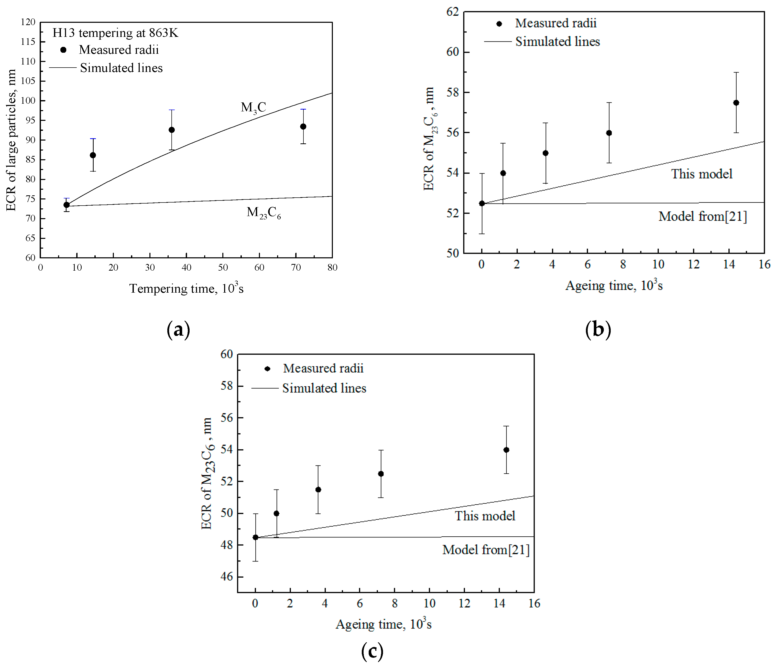
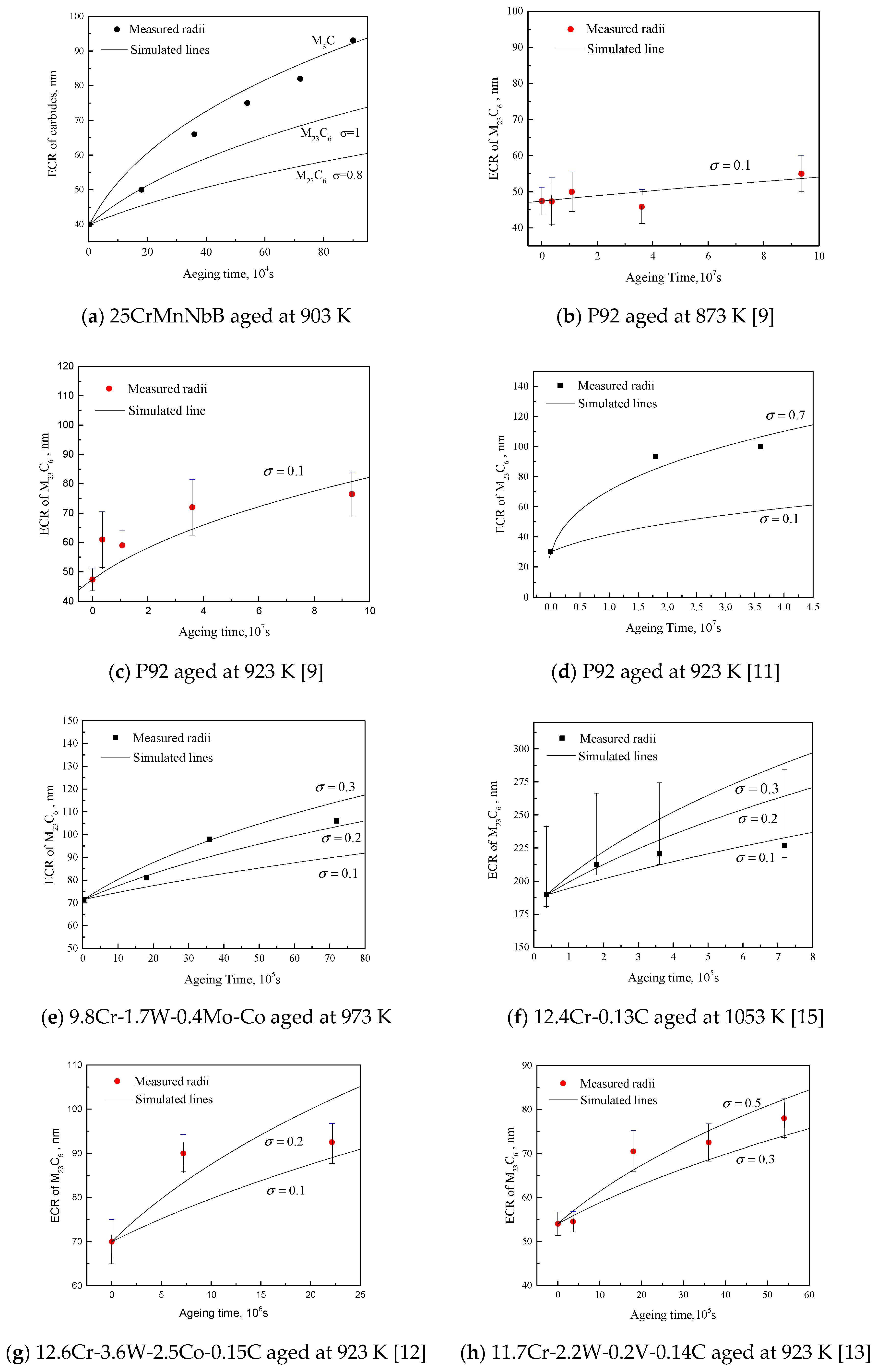
5. Verification of Ostwald Ripening Model

Hu et al. [25] has simulated the coarsening of M23C6 in H13 and H13Nb steel ageing at 973 K, but his simulation does not match the experimental data well, compared to the model developed in this paper (Figure 10b,c). The specific values are listed in Table 6. In this table, the experimental data come from literature and simulation results of M23C6 are listed for comparison. The agreement is satisfactory, although the experiment fitting values of m are a little higher than the simulated value both in H13 and H13Nb.
The M23C6 coarsening rate of another steel, 25CrMoNbB, is also calculated by this model, as shown in Figure 11a. In this simulation, the diffusivities of all elements dissolved in M23C6 are set to be one order of magnitude higher than the calculated values at 903 K (Equation (6-10)), because boron tends to accelerate precipitation of M23C6 [43]. The interfacial energy is set near the maximum value 1 J/m2, but the coarsening rate is still lower than the experimental data (Table 6). However, H13 and 25CrMoNbB contain M3C precipitates at 873 K, 973 K and 903 K. Since it is difficult to distinguish M3C and M23C6 by shape and size, the experimental data of M23C6 may include some M3C in their work, so that the average radii are larger than simulation values. The simulated coarsening of M3C in these two steels are also calculated for comparison (Table 6).
The other steels listed in Table 6 belong to heat resistant steels used in power plant. The ageing temperature ranges from 873 K–1053 K. The steels contain 9–12% Cr and other alloying elements such as Mn, Mo and W. These alloying elements all participate in the formation of M23C6 and will influence its coarsening speed during their ageing or service time. In high-alloyed steels, the diffusivities of alloying elements will be depressed by other elements. It is thus a rather complex interplay between thermodynamics of solution and kinetic processes that determines the coarsening rate of M23C6 in high Cr steel. Based on this, the diffusivities of alloying elements in steels like P91, P92, 10% Cr and 12% Cr are set one order of magnitude lower than the ones calculated from Equations (6)–(11), except for one steel 12.4% Cr-0.13%C [15]. Because this steel is a ternary alloy with only Fe, Cr and C, the diffusivity of Cr is calculated from Equation (7). All the results are listed in Table 6 and plotted in Figure 11 b–h comparing the experimental data in the literature with the simulation model of this work.
From Figure 11a–h, the coarsening model is basically in accord with the experimental data, and at least within the same order of magnitude. Thus, this model is generally effective for the prediction of M23C6 coarsening both in low Cr and high Cr steels.

6. Conclusions

A model to predict the coarsening of ‘large’ carbides, i.e., M23C6 and M3C, was generated using tempering data from an H13 steel. The model which is based on the LSW and Ostwald ripening theory is effective to simulate kinetic behavior of precipitates in multicomponent alloy system. The model was also deployed to fit the experimental data of other five kinds of low and high Cr steels. The coarsening rate calculated by this model showed good agreement with these steels.

Author Contributions

A.N. carried out the experiments and analyzed the results. R.G. ran the FactSage software for thermodynamic calculations. L.L. carried out the electrolysis experiment of H13. S.Y. contributed to the discussion of the results and revision of the manuscript. H.G. and S.Y. covered all the testing fees in this work.

Funding

This research was funded by China Scholarship Council, No. 201806935054. This work was also supported by Scientific and Technological Innovation Programs of Higher Education Institutions in Shanxi, China, No. 201802035.

Acknowledgments

The authors acknowledge with gratitude for HR-TEM experiment provided by State Key Laboratory of Advanced Metals and Materials in University of Science and Technology Beijing, China. The authors also appreciated Iron and Steel Research Institute (CISRI) for the experiment of organic electrolysis and the supplying of H13 forging sample.

Conflicts of Interest

The authors declare no conflict of interest.

References

  1. Zhao, Y.G.; Liang, Y.H.; Zhou, W.; Qin, Q.D.; Jiang, Q.C. Effect of current pulse on the thermal fatigue behavior of cast hot work die steel. ISIJ Int. 2005, 45, 410–412. [Google Scholar] [CrossRef]
  2. Perez, M.; Belzunce, F.J. The effect of deep cryogenic treatments on the mechanical properties of an AISI H13 steel. Mater. Sci. Eng. A 2015, 624, 30–40. [Google Scholar] [CrossRef]
  3. Liu, H.; Fu, P.; Liu, H.; Sun, C.; Gao, J.; Li, D. Carbides Evolution and Tensile Property of 4Cr5MoSiV1 Die Steel with Rare Earth Addition. Metals 2017, 7, 436. [Google Scholar] [CrossRef]
  4. Kheirandish, S.; Noorian, A. Effect of niobium on microstructure of cast AISI H13 hot work tool steel. J. Iron Steel Res. Int. 2008, 15, 61–66. [Google Scholar] [CrossRef]
  5. Li, J.Y.; Yu, L.C.; Huo, J.H. Mechanism of improvement on strength and toughness of H13 die steel by nitrogen. Mater. Sci. Eng. A 2015, 640, 16–23. [Google Scholar] [CrossRef]
  6. Kang, M.; Park, G.; Jung, J.G.; Kim, B.H.; Lee, Y.K. The effects of annealing temperature and cooling rate on carbide precipitation behavior in H13 hot-work tool steel. J. Alloys Compd. 2015, 627, 359–366. [Google Scholar] [CrossRef]
  7. Zhu, J.; Zhang, Z.H.; Xie, J.X. Improving strength and ductility of H13 die steel by pre-tempering treatment and its mechanism. Mater. Sci. Eng. A 2019, 752, 101–114. [Google Scholar] [CrossRef]
  8. Zheng, Y.X.; Wang, F.M.; Li, C.R.; Li, Y.L.; Cheng, J. Microstructural evolution, coarsening behavior of precipitates and mechanical properties of boron bearing steel 25CrMoNbB during tempering. Mater. Sci. Eng. A 2018, 712, 453–465. [Google Scholar] [CrossRef]
  9. Gustafson, A.; Hattestrand, M. Coarsening of precipitates in an advanced creep resistant 9% chromium steel—Quantitative microscopy and simulations. Mater. Sci. Eng. A 2002, 333, 279–286. [Google Scholar] [CrossRef]
  10. Hald, J.; Korcakova, L. Precipitate stability in creep resistant ferritic steels-experimental investigations and modelling. ISIJ Int. 2003, 43, 420–427. [Google Scholar] [CrossRef]
  11. Sakthivel, T.; Selvi, S.P.; Parameswaran, P.; Laha, K. Influence of thermal ageing on microstructure and tensile properties of P92 steel. High Temp. Mater. Process. 2018, 37, 425–435. [Google Scholar] [CrossRef]
  12. Garcia, J.; Rojas, D.; Carrasco, C.; Kaysser-Pyzalla, A.R. Investigations on coarsening of MX and M23C6 precipitates in 12% Cr creep resistant steels assisted by computational thermodynamics. Mater. Sci. Eng. A 2010, 527, 5976–5983. [Google Scholar]
  13. Xiao, X.; Liu, G.Q.; Hu, B.F; Wang, J.S.; Ma, W.B. Coarsening behavior for M23C6 carbide in 12%Cr-reduced activation ferrite/martensite steel: Experimental study combined with DICTRA simulation. J. Mater. Sci. 2013, 48, 5410–5419. [Google Scholar] [CrossRef]
  14. Gao, Q.Z.; Zhang, Y.N.; Zhang, H.L.; Li, H.J.; Qu, F.; Han, J.; Cheng, L.; Wu, B.T.; Lu, Y.; Ma, Y. Precipitates and Particles Coarsening of 9Cr-1.7W-0.4Mo-Co Ferritic Heat-Resistant Steel after Isothermal Aging. Sci. Rep. 2017, 7, 5859. [Google Scholar] [CrossRef]
  15. Zhu, N.Q.; Lu, L.; He, Y.L.; Li, L.; Lu, X.G. Coarsening of M23C6 Precipitates in an Fe-Cr-C Ternary Alloy. J. Iron Steel Res. Int. 2012, 19, 62–67. [Google Scholar] [CrossRef]
  16. Fu, X.Y.; Bai, P.C.; Yang, J.C. Cracking the initiation mechanism of high Cu-bearing nitrogen-alloyed austenitic stainless steel in the process of hot deformation. Metals 2018, 8, 816. [Google Scholar] [CrossRef]
  17. Ning, A.G.; Mao, W.W.; Chen, X.C.; Guo, H.J.; Guo, J. Precipitation behavior of carbides in H13 hot work die steel and its strengthening during tempering. Metals 2017, 7, 70. [Google Scholar] [CrossRef]
  18. Song, W.W.; Min, Y.A.; Wu, X.C. Study on carbides and their evolution in H13 hot work steel. Trans. Mater. Heat Treat. 2009, 30, 122–126. [Google Scholar]
  19. Delagnes, D.; Lamesle, P.; Mathon, M.H.; Mebarki, N.; Levaillant, C. Influence of silicon content on the precipitation of secondary carbides and fatigue properties of a 5%Cr tempered martensitic steel. Mater. Sci. Eng. A 2005, 394, 435–444. [Google Scholar] [CrossRef]
  20. Mao, W.; Ning, A.; Guo, H. Nanoscale precipitates and comprehensive strengthening mechanism in AISI H13 steel. Int. J. Miner. Metall. Mater. 2016, 23, 1056–1064. [Google Scholar] [CrossRef]
  21. Hu, X.B.; Li, L.; Wu, X.C.; Zhang, M. Coarsening behavior of M23C6 carbides after ageing or thermal fatigue in AISI H13 steel with niobium. Int. J. Fatigue 2006, 28, 175–182. [Google Scholar] [CrossRef]
  22. Totten, G.E. Steel Heat Treatment: Metallurgy and Technologies; CRC Press: Boca Raton, FL, USA, 2006. [Google Scholar]
  23. Michaud, P.; Delagnes, D.; Lamesle, P.; Mathon, M.H.; Levaillant, C. The effect of the addition of alloying elements on carbide precipitation and mechanical properties in 5% chromium martensitic steels. Acta Mater. 2007, 55, 4877–4889. [Google Scholar] [CrossRef]
  24. Ning, A.G.; Guo, H.J.; Chen, X.C.; Wang, M.B. Precipitation behaviors and strengthening of carbides in H13 steel during annealing. Mater. Trans. 2015, 56, 581–586. [Google Scholar]
  25. Zheng, Y.X.; Wang, F.M.; Li, C.R.; He, Y.T. Dissolution and precipitation behaviors of boron bearing phase and their effects on hardenability and toughness of 25CrMoNbB steel. Mater. Sci. Eng. A 2017, 701, 45–55. [Google Scholar] [CrossRef]
  26. Cui, Z.Q.; Oin, Y.C. Metal Science and Heat Treatment; Machinery Industry Press: Beijing, China, 2007. [Google Scholar]
  27. Yan, G.H.; Han, L.Z.; Li, C.W.; Luo, X.M.; Gu, J.F. Characteristic of retained austenite decomposition during tempering and its effect on impact toughness in SA508 gr.3 steel. J. Nucl. Mater. 2017, 483, 167–175. [Google Scholar] [CrossRef]
  28. Mittemeher, E.J.; Cheng, L.; van der Schaaf, P.J.; Brakman, C.M.; Korevaar, B.M. Analysis of nonisothermal transformation kinetics; tempering of iron-carbon and iron-nitrogen martensites. Metall. Trans. A 1988, 19, 925–932. [Google Scholar] [CrossRef]
  29. Lifshitz, I.M.; Slyozov, V.V. The kinetics of precipitation from supersaturated solid solutions. J. Phys. Chem. Solids 1961, 19, 35–50. [Google Scholar] [CrossRef]
  30. Wagner, C. Theory of precipitate change by redissolution. Z. Elektrochem. 1961, 65, 581–591. [Google Scholar]
  31. Seher, R.J.; James, H.M.; Maniar, G.N. Stereology and Quantitative Metallography, West Conshohocken; Pellissier, G.E., Purdy, S.M., Eds.; ASTM International: West Conshohocken, PA, USA, 1972; pp. 119–137. [Google Scholar]
  32. Kneissl, A.C.; Garcia, C.I.; Deardo, A.J. HSLA Steels: Processing, Properties, and Applications; Geoffrey, T., Zhang, S., Eds.; The Minerals, Metals and Materials Society: San Diego, CA, USA, 1992; pp. 99–102. [Google Scholar]
  33. Leslie, W.C. Iron and its dilute substitutional solid solution. Metall. Trans. 1972, 3, 5–26. [Google Scholar] [CrossRef]
  34. Rade, L.; Westergren, B. Beta Mathematics Handbook, Studentlitteratur; Lund University Press: Lund, Sweden, 1993. [Google Scholar]
  35. Clarke, K.D.; Van-Tyne, C.J.; Vigil, C.J.; Hackenberg, R.E. Induction hardening 5150 steel: Effects of initial microstructure and heating rate. J. Mater. Eng. Perform. 2011, 20, 161–168. [Google Scholar] [CrossRef]
  36. Sadhan, G. Rate-controlling parameters in the coarsening kinetics of cementite in Fe-0.6C steels during tempering. Scr. Mater. 2010, 63, 273–276. [Google Scholar]
  37. Bjorklund, S.; Donaghey, L.F; Hillert, M. The effect of alloying elements on the rate of Ostwald ripening of cementite in steel. Acta Metall. 1972, 20, 867–874. [Google Scholar] [CrossRef]
  38. Martin, J.W.; Doherty, R.D.; Cantor, B. Stability of Microstructure in Metallic System, 2nd ed.; Cambridge University Press: Cambridge, UK, 1997. [Google Scholar]
  39. Philippe, T.; Voorhees, P.W. Ostwald ripening in multicomponent alloys. Acta Mater. 2013, 61, 4237–4244. [Google Scholar] [CrossRef]
  40. Umantsev, A.; Olson, G.B. Ostwald ripening in multicomponent alloys. Scr. Metall. Mater. 1993, 29, 1135–1140. [Google Scholar] [CrossRef]
  41. Faranak, N.; Johann, H.A.; Philippe, B. Modeling of cementite coarsening during tempering of low-alloyed-medium carbon steel. J. Mater. Sci. 2018, 53, 6198–6218. [Google Scholar]
  42. Yong, Q.L. Secondary Phases in Steels; Metallurgical Industry Press: Beijing, China, 2006. [Google Scholar]
  43. Tsumura, T.; Okada, Y.; Ohtani, H. Effect of microalloying elements on the hardenability and the properties after tempering at high temperature in boron treated Cr-Mo-Nb steels. ISIJ Int. 1986, 72, 1367–1374. [Google Scholar]
Figure 1. Heat treatment of AISI H13 steel.
Metals 09 01283 g001aMetals 09 01283 g001b
Figure 2. Positions of the H13 samples: (a) Large sample taken from the middle of the ingot after annealing; (b) Individual test samples taken near surface of (a) before tempering.
Metals 09 01283 g002
Figure 3. Mechanical properties of H13 with tempering time.
Metals 09 01283 g003
Figure 4. Metallographic images of H13 after tempering at 863 K.
Metals 09 01283 g004
Figure 5. SEM (scanning electron microscope) images of nital etched specimens. (a) As-quenched; (b) Tempering for 20 h; (c) EDS (energy dispersive spectrometer) analysis of typical carbides in as-quenched sample.
Metals 09 01283 g005
Figure 6. XRD (X-Ray diffraction) result of precipitates in H13 after electrolysis.
Metals 09 01283 g006
Figure 7. TEM (transmission electron microscope) carbon replicas of precipitates after tempering at 863 K.
Metals 09 01283 g007
Figure 8. Distribution of carbides after different tempering time.
Metals 09 01283 g008
Figure 9. FactSage thermodynamic calculations based on: (a) Equilibrium; (b) Scheil-Gulliver cooling for H13 steel.
Metals 09 01283 g009
Figure 10. Comparison of prediction by Ostwald ripening model and experimental data. (a) Large carbides’ coarsening at 863 K (b) M23C6 coarsening in H13 at 973 K (c) M23C6 coarsening in H13Nb at 973 K.
Metals 09 01283 g010
Figure 11. Comparison with experiment data in literatures and simulation results by this coarsening model.
Metals 09 01283 g011
Table 1. Chemical composition of H13.
CSiMnPSCrNiCuMoVAl
0.390.980.380.00110.00065.090.0830.0541.390.90.047
Table 2. Number and average radius of each range observed by TEM.
Radius Range (nm)0.5 h2 h4 h10 h20 h
NumberAverage Radius (nm)NumberAverage Radius (nm)NumberAverage Radius (nm)NumberAverage Radius (nm)NumberAverage Radius (nm)
55–6517259.5 30459.6 12260.1 8959.8 12159.7
65–758369.2 14069.7 9670.1 6569.8 9569.8
75–855079.1 10979.1 7479.8 4079.6 6579.8
85–953889.1 3889.8 4390.2 2590.3 3889.8
95–1052899.6 2699.2 2199.5 1599.8 3499.4
105–11516109.3 18109.5 18109.4 15109.2 21109.8
115–12514119.6 9118.4 12119.5 9120.7 16120.4
125–1359130.6 6129.4 8130.0 3128.9 14130.5
135–1457141.5 1139.6 4138.8 8140.1 4138.0
145–1555151.7 4151.0 4149.4 2149.3 9149.4
155–1652157.9 3160.1 5163.3 6158.9 6161.6
165–1752168.2 1170.2 00.0 5169.5 5170.2
175–18500.0 1179.3 1183.4 7179.9 6182.5
185–3553229.3 5198.3 14273.9 17231.9 25247.8
Table 3. The size, distribution and strengthening of large carbides.
TemperingMeasured Number of Large Particles (55–355 nm)Average ECR of Large Particles (nm)Volume of Large Particles (%)Strengthening of Large Particles (MPa)
0.5 h42978.8 ± 2.42.74255.8
2 h66573.5 ± 1.74.22265.3
4 h42286.2 ± 4.24.98262.9
10 h30692.6 ± 5.14.19243.7
20 h45993.5 ± 4.44.87239.5
Table 4. Solubilities and diffusivities used for the calculation of coarsening rate of M23C6 in H13 steel. The m values are based on an interfacial energy of 0.5 J/m2.
M23C6 T x i α x i β D i T x i α x i β D i
Cr8630.04940.50765.47 × 10−159730.04590.45402.85 × 10−13
Mn8630.00302.6 × 10−61.69 × 10−149730.00287.7 × 10−65.41 × 10⁻¹³
V8630.00741.4 × 10−61.01 × 10−149730.00778.9 × 10−64.52 × 10⁻¹³
Mo8630.00570.10331.79 × 10−149730.00430.10266.60 × 10−13
m0.38 nm / s 1 3 1.39 nm / s 1 3
Table 5. Solubilities and diffusivities used for the calculation of coarsening rate of cementite in H13 steel. The shown m values are based on an interfacial energy of 0.45 J/m2 and 0.38 J/m2.
M3CT x i α x i β D i T x i α x i β D i
Cr8630.04940.05605.47 × 10−159730.05120.06462.85 × 10−13
Mn8630.00300.02571.69 × 10−149730.00270.02805.41 × 10−13
V8630.00740.00441.01 × 10−149730.00850.03104.52 × 10−13
Mo8630.00570.02511.79 × 10−149730.00640.01606.60 × 10−13
m2.09 nm / s 1 3 5.89 nm / s 1 3
Table 6. Comparison of M23C6 coarsening in different steels.
PrecipitatesTSteelExperimental Data in LiteraturesPrediction of the Model in This Work (Formula (4))
m   ( nm / s 1 3 ) σ   ( J / m 2 ) m   ( nm / s 1 3 ) σ   ( J / m 2 )
M23C6863 KH13(this work)--0.380.5
873 KP92 [9]0.0790.1-0.50.0810.1
P92 [10]0.110.10.0810.1
P91 [10]0.311.00.281.0
903 K25CrMoNbB [8]0.88-0.591
923 KP92 [9]0.170.1-0.30.170.1
P92 [10]0.240.10.170.1
P91 [10]0.630.80.480.8
P92 [11]0.32-0.320.7
12.6Cr-3.6W-2.5Co-0.15C [12]0.270.30.320.2
11.7Cr-2.2W-0.2V-0.14C [13]0.400.50.420.5
973 KH13 [21]1.540.51.400.5
H13Nb [21]1.520.51.240.5
9.8Cr-1.7W-0.4Mo-Co [14]0.38-0.370.1
1053 K12.4Cr-0.13C [15]2.070.1–0.32.040.1
M3C863 KH13(this work)--2.090.45 [42]
973 KH13 [21]--5.890.38 [42]
903 K25CrMoNbB [8]--0.930.43 [42]
Note: The interfacial energy deployed by this work is consistent with the one from literatures, in order to compare the experiment and calculation results. Due to long time ageing, all the thermodynamic calculations listed in Table 6 are under equilibrium state except calculation of M3C in H13.

