Article

Mechanical Properties of Ti-15Mo Alloy Prepared by Cryogenic Milling and Spark Plasma Sintering

1
Department of Physics of Materials, Charles University, 121 16 Prague, Czech Republic
2
Institute of Plasma Physics, Czech Academy of Sciences, 182 00 Prague, Czech Republic
*
Author to whom correspondence should be addressed.
Metals 2019, 9(12), 1280; https://doi.org/10.3390/met9121280
Submission received: 18 October 2019 / Revised: 14 November 2019 / Accepted: 26 November 2019 / Published: 28 November 2019

Abstract

:
Metastable β-Ti alloy Ti-15Mo was prepared by cryogenic ball milling in a slurry of liquid argon. Material remained ductile even at low temperatures, which suppressed particle refinement, but promoted intensive plastic deformation of individual powder particles. Repetitive deformation of powder particles is similar to the multidirectional rolling and resembles bulk severe plastic deformation (SPD) methods. Initial and milled powders were compacted by spark plasma sintering. Sintered milled powder exhibited a refined microstructure with small β-grains and submicrometer sized α-phase precipitates. The microhardness and the yield tensile strength of the milled powder after sintering at 850 °C attained 350 HV and 1200 MPa, respectively. Low ductility of the material can be attributed to high oxygen content originating from the cryogenic milling. This pioneering work shows that cryogenic milling followed by spark plasma sintering is able to produce two-phase β-Ti alloys with refined microstructure and very high strength levels.

1. Introduction

Metastable β-alloys constitute a specific group of Ti alloys in which none of the α-phase, α’-phase or α″-phase form after quenching from a temperature above the temperature of β-transus (774 °C for Ti-15Mo [1]). β-Ti alloys are widely used in the aircraft industry due to their high specific strength [2]. Utilization of these alloys in biomedicine is also expected [3]. Currently, Ti-6Al-4V is a commonly used alloy for biomedical implants manufacturing, despite vanadium being considered as a toxic element [4]. Therefore, Ti-15Mo, which contains only biocompatible elements, is a perspective biocompatible alternative. Furthermore, β-Ti alloys in β-solution treated condition exhibit lower modulus of elasticity, which is closer to that of a human bone [5].
Mechanical properties of metastable β-Ti alloys can be further improved by thermomechanical treatment. Both microstructure refinement and precipitation of α-phase increase the strength of the alloy. α-phase particles precipitate typically at temperatures in the range of 500–750 °C. During this phase transformation, so-called element partitioning occurs. β-stabilizing elements (molybdenum (Mo), niobium (Nb), vanadium (V), etc.) diffuse from the growing α-phase particles to the surrounding β-matrix [6,7]. In addition to α and β-phase, metastable ω-phase can also occur in some metastable β-alloys including Ti-15Mo alloy. During quenching, so-called ωath (athermal) forms by a displacive transformation. When annealing at temperatures in range 250–450 °C, ωiso (isothermal) forms by a diffusional transformation [8]. ω-phase also strengthens the material.
Powder metallurgy is an alternative and often more suitable way of producing titanium alloys [9,10]. Due to the possibility of near-net-shape processing, the material waste and costs associated with the material processing are reduced. Spark plasma sintering (SPS) was used as a compaction method in this study. During SPS, the powder is compacted by pulse electric current and the powder particles are joined together by the Joule heat. The sintering therefore occurs primarily at the point of contact of powder particles [11]. Therefore, lower temperatures and shorter times are sufficient for compaction in comparison to other compaction methods. Utilization of SPS for compaction helps therefore to preserve the fine microstructure and restrict the grain growth [11,12].
Elemental powders, master alloys or pre-alloyed powder can be used for sintering. Sintering of elemental powders or master alloys must provide alloying (homogenization) of the material and therefore high sintering temperatures (1200–1700 °C) must be used for processing of metastable β-Ti alloys due to high melting points of β-stabilizing elements and their low diffusivity [2,13]. On the other hand, successful compaction of pre-alloyed powder can be achieved at temperatures comparable to the temperature of β-transus of an alloy [14].
Besides the parameters of sintering, the final bulk material is also affected by the shape, the size and the microstructure of powder particles [14]. Mechanical milling is commonly used to fragment powder particles [15]. In this study, intensive ball milling at cryogenic temperatures was used. Cryogenic temperatures are often used for milling of organic materials to ensure their brittleness [16]. In metallic materials, cryogenic temperatures help to suppress dynamic recovery and recrystallization and to achieve very refined microstructure [17].
Cryogenic milling employing the Szegvari type attritor has been previously applied to commercially pure titanium [18,19,20,21]. It was found that titanium remains ductile even at cryogenic temperatures (unless contaminated by nitrogen [21]) and powder particles are not significantly refined [22]. On the other hand, powder particles are significantly deformed by repetitive plastic deformation [15,22,23]. In our previous study we proved that deformation by ball milling resembles the multi-directional forging and causes grain refinement [24]. In this respect, mechanical milling can be regarded as a method of severe plastic deformation (SPD). Various metastable β-Ti alloys have been prepared by SPD methods and improvement of strength was reported [25,26]. Recently the Ti-15Mo alloy was prepared by high pressure torsion (HPT), which caused the grain refinement and an increase of dislocation density [27,28]. On the other hand, HPT samples are very small and thermal stability of ultra-fine grained Ti alloys prepared by SPD methods is limited [29,30]. Similarly to bulk SPD methods, grain size after cryogenic milling can be reduced to tens of nanometers as shown for commercially pure Ti (CP Ti) in [22]. However, the grain size in CP Ti significantly increases after sintering due to recrystallization [24].
Ti-15Mo pre-alloyed powder was milled in liquid argon slurry. Note that liquid nitrogen cannot be used, because N atoms diffuse into the powder during milling causing embrittlement [21,31]. In order to prevent cold welding of the powder to the milling tank, shaft and balls, a process control agent such as stearic acid must be added to it [15,22].
Milled powder was subsequently sintered at temperatures in the range of 750–850 °C for 3 min. For comparison, initial gas atomized powder was sintered using the same parameters. Due to the fact that titanium is a strong gatherer of nitrogen and oxygen, some contamination is unavoidable during powder metallurgy processing [22,32]. Therefore, contamination by oxygen, nitrogen (and possibly by carbon and hydrogen) must be always monitored in order to assess strengthening mechanisms appropriately.

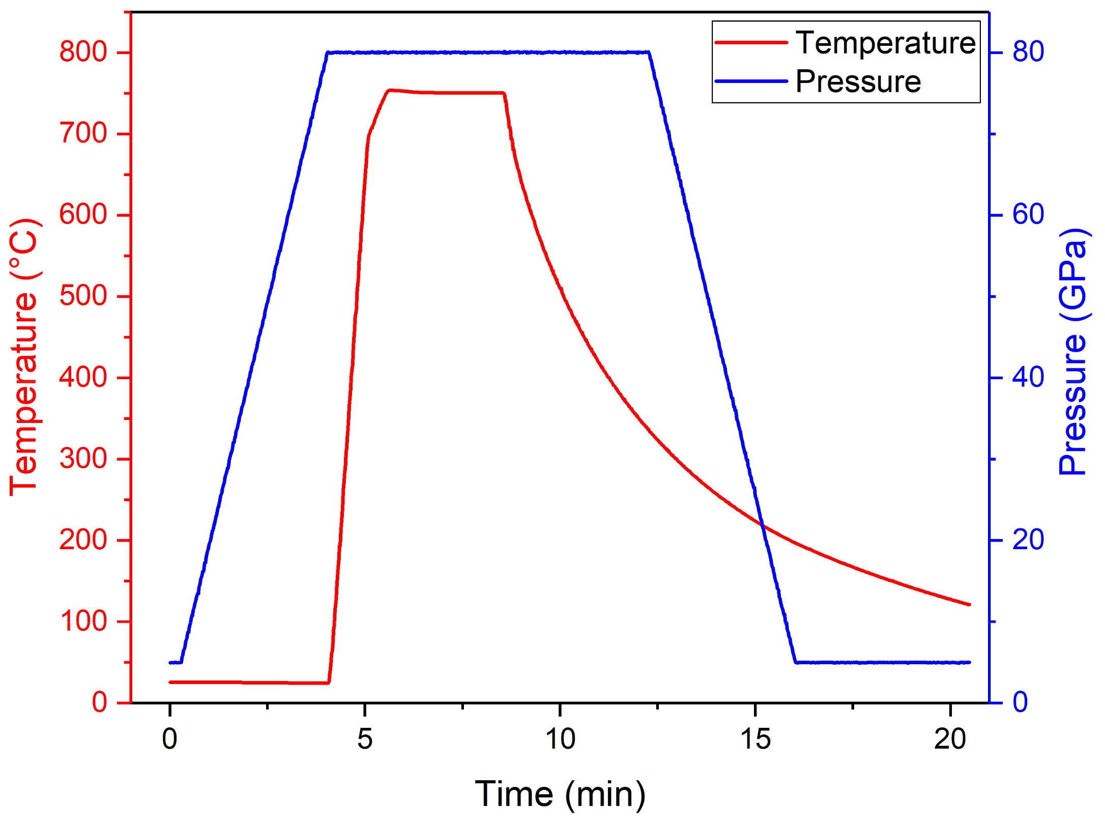
2. Materials and Methods

Ti-15Mo powder was prepared by gas atomization and supplied by TLS Technik GmbH and Co. Spezialpulver KG, Bitterfeld-Wolfen, Germany.
The milling was performed for 4 h at 700 revolutions per minute (RPM) milling speed in Union Process 01-HD (Union Process, Akron, OH, USA) attritor (1400 cm3) device in liquid argon. Stainless steel balls of a diameter 6.35 mm and ball to powder ratio (BPR) 16:1 were used. 1.8 g of stearic acid was added into 180 g of Ti-15Mo powder as a process control agent to prevent cold welding.
Both gas atomized (initial) and cryo-milled (referred to as milled) powders were compacted by a spark plasma sintering (SPS) device by FCT Systeme GmbH (Rauenstein, Germany). The sintering was performed for 3 min in the temperature range from 750 °C to 850 °C. The temperature was measured by a thermocouple inserted into the graphic die 4 mm from the sintered sample. The powder was compressed by a pressure of 80 GPa and heated 50 °C below the desired temperature always in one minute (heating rates were from 700 °C/min to 800 °C/min depending on the sintering temperature). The sample was subsequently heated up to the desired sintering temperature with the heating rate of 100 °C/min. These two steps were designed to avoid temperature overshooting. The example of the temperature and pressure evolution during sintering at the temperature of 750 °C is shown in Figure 1. The cooling was not actively controlled.
Scanning electron microscope (SEM) observations were performed with the scanning electron microscope FEI Quanta 200F (FEI, Hillsboro, OR, USA). For this purpose, both initial and milled powders were simply stuck on a conductive foil. Bulk samples for SEM microstructural observations were prepared by standard mechanical grinding and polishing followed by the three step vibratory polishing. Fracture surface after tensile tests were also observed.
The fraction of the α-phase and porosity of samples were determined by image analysis in ImageJ (version 1.52r, Wayne Rasband, Research Services Branch, National Institute of Mental Health, Bethesda, MD, USA). For this purpose, 10 micrographs of size of about 1000 μm2 from each sample were made by a scanning electron microscope FEI Quanta 200F operated at 10 kV and at 5 kV in case of sintered initial powder and sintered milled powder, respectively. The fraction of the α-phase was determined from electron back-scatter (BSE) micrographs. Porosity of samples sintered from initial powder was determined by image analysis from secondary electron (SE) micrographs. The very low overall porosity of sintered milled powder disallowed its determination by image analysis. The Archimedes method was used instead. The error of this measurement is given only by the precision of the sample weighing, which is 0.5 mg. For comparison, the porosity of the initial powder sintered at 800 °C was measured by both methods. It was found that image analysis underestimates the overall porosity and Archimedes method proved to be more reliable. Porosity of sintered initial powder was therefore calibrated according to the porosity of the initial powder sintered at 800 °C.
Contamination of material by oxygen was determined in powders as well as in selected sintered samples by carrier gas hot extraction (CGHE). The microhardness was measured by the Vickers method (0.5 kgf load, 30 indents per sample) using Qness Q10a (Qness, Golling, Austria) instrument with automatic evaluation of the measurement.
X-ray diffraction (XRD) measurements were performed on a Bruker D8 Advanced diffractometer (Bruker AXS, Karlsruhe, Germany) in Bragg–Brentano geometry using Cu Kα radiation, λ = 1.54051 Å, variable divergence slits and a Sol-X detector. Bragg–Brentano geometry is an arrangement in which the incident and diffracted beams are focused on a circle with the measured sample in the middle. Diffraction patterns were collected at room temperature in the 2 range from 30° to 130° with a step size of 0.02° and an exposure time of 5 s/step. The patterns were fitted and refined employing le Bail algorithm with a pseudo-Voigt profile using program Jana2006 (V. Petríček, M. Dušek and L. Palatinus, Institute of Physics Academy of Sciences, Prague, Czech Republic).
The position of the flat dog-bone shaped tensile sample in the sintered tablet is shown in Figure 2. The sample was 20 mm long and its gauge length was 5 mm. The total width was 7 mm while the gauge length and thickness were 1.2 mm and 1 mm, respectively. The diameter of the hole for the pin was 2.3 mm. The “bricks” in Figure 2 symbolize arrangement of flat milled powder particles in the tensile sample caused by their stacking in the sintering die [24]. Tensile tests were performed at Instron 5882 machine. The constant crosshead velocity was 0.03 mm/s, resulting in the initial strain rate of ε ˙ = 10 4 s 1 .

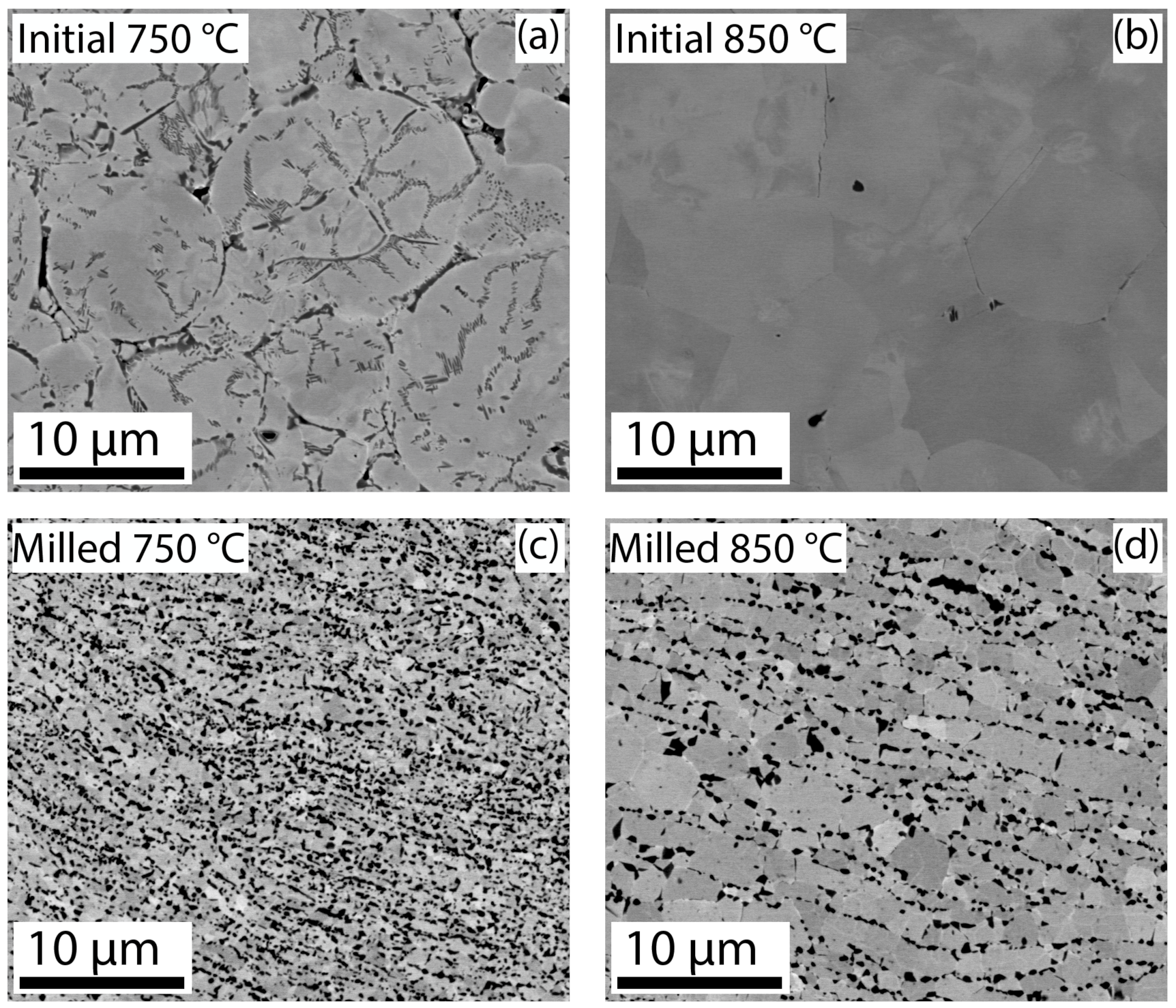
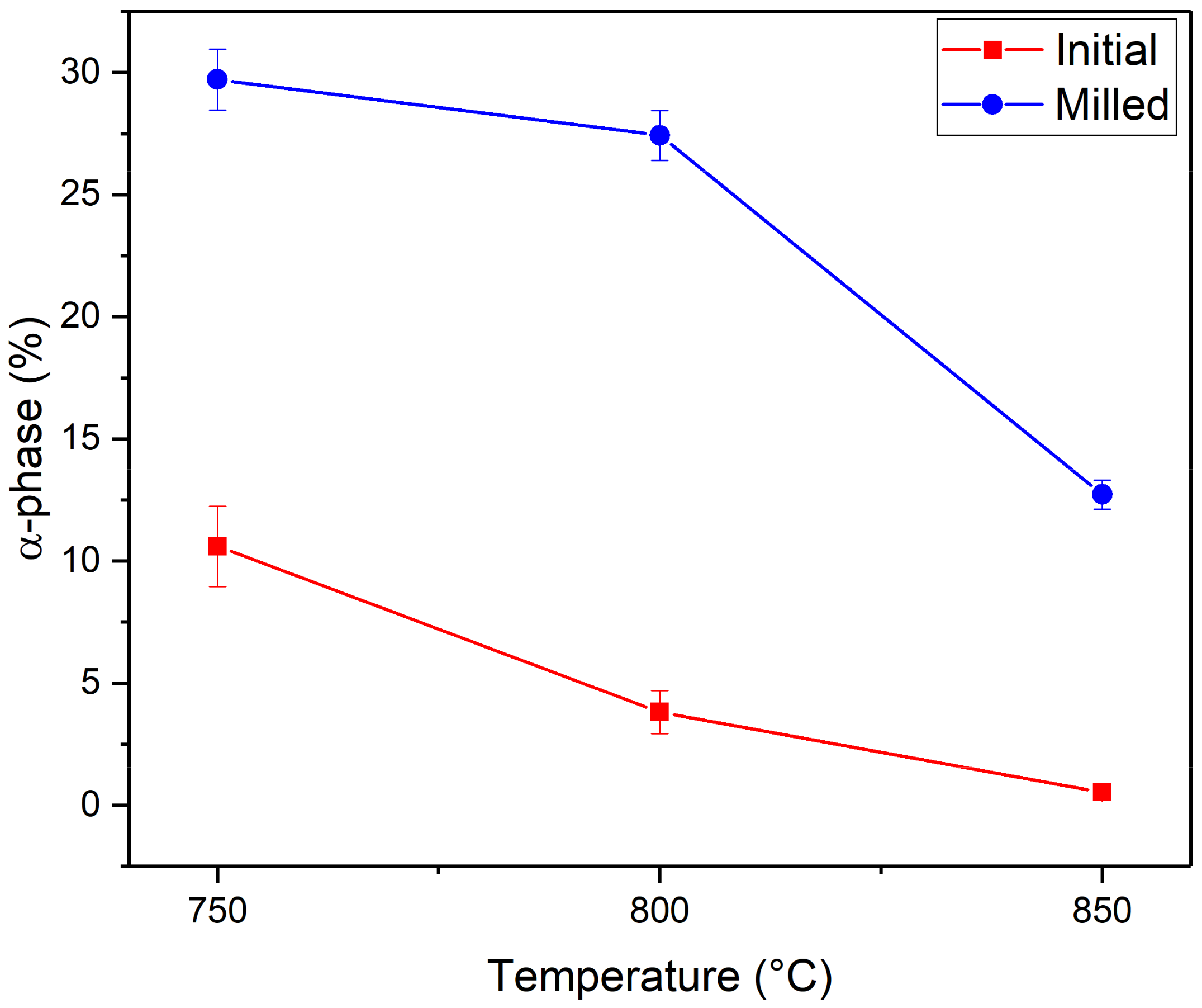
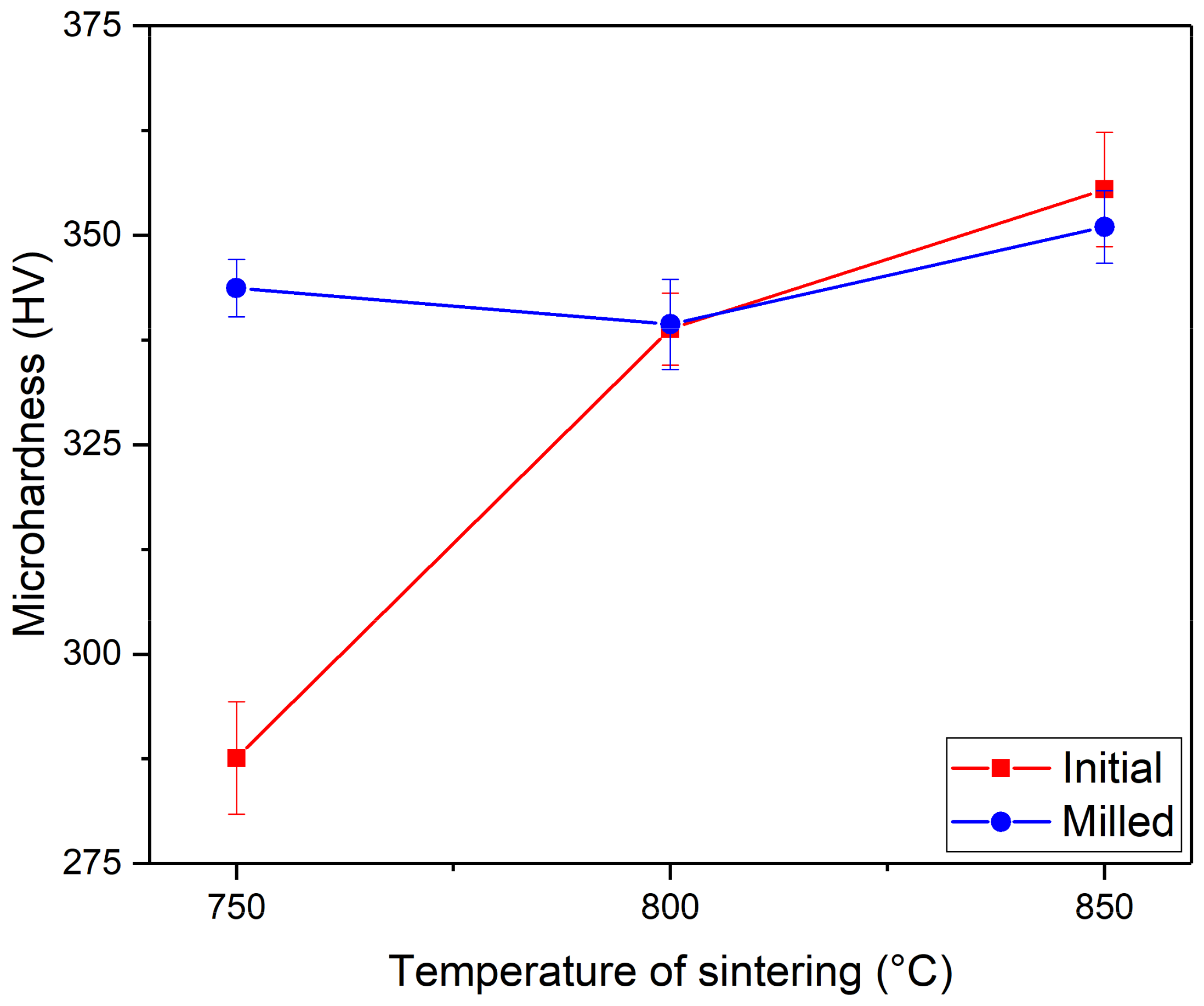
3. Results and Discussion

3.1. Cryogenic Milling

The SEM micrograph of gas atomized Ti-15Mo powder is shown in Figure 3a. The initial gas-atomized powder particles are ball-shaped with the size from several μm up to 30 μm. Powder particles after cryomilling are shown in Figure 3b. Powder particles were not refined by cryomilling due to high ductility of titanium and its alloys even at low temperatures [22]. Powder particles were, however, plastically deformed and changed their shape from balls to disks. The size of disk-shaped powder particles is up to around 50 μm.
The contamination by oxygen (shown in Table 1) increased during milling from 0.20 wt. % to 0.78 wt. % despite milling in inert atmosphere of liquid argon. It was previously shown that handling powders in a glove box does not reduce the contamination significantly and therefore it is assumed that contamination origins from the milling [16]. Contamination during milling can be caused both by addition of the process control agent—the stearic acid—and by contamination from the used liquid argon, which may contain some trace amount of oxygen. It has been calculated that adding of 1 wt. % of stearic acid can cause contamination by oxygen by 0.11 wt. %. On the other hand, almost 100 L of 99.999% purity argon was used to mill 180 g of powder. The total content of oxygen in the liquid argon (Ar) corresponds to about 0.5 wt. % of oxygen in the milled powder. Some additional oxygen may be also absorbed.

3.2. Spark Plasma Sintering

Contamination of samples sintered at 750 °C and 850 °C is shown in Table 2. The content of oxygen in the initial powder slightly increased after sintering, while in the milled powder, it decreased due to the decomposition of stearic acid at high temperatures. The sintering temperature did not have a significant effect on contamination by oxygen for both initial and milled powders.
Figure 4 shows BSE micrographs of sintered powders. Black areas in these BSE figures are α-phase, pores and impurities from polishing. In order to analyze images, these three phenomena were distinguished using SE observation. SE micrographs of the same areas as in Figure 4 are shown in Figure 5. In SE signal, pores are black, impurities from polishing are white and the α-phase is grey.
SEM micrographs of initial powder sintered at 750 °C and at 850 °C are shown in Figure 4 and Figure 5. Initial powder sintered at 750 °C (Figure 4a and Figure 5a) contains a significant amount of α-phase while initial powder sintered at 850 °C (cf. Figure 4b and Figure 5b) contains only a small amount of grain boundary α-phase and black areas in BSE micrographs are mostly impurities from polishing. BSE micrographs of milled powder sintered at 750 °C and at 850 °C are shown in Figure 4c,d, respectively and in Figure 5c,d, respectively. Sintered milled powder has finer microstructure and contains higher amount of α-phase in comparison with the initial one. With increasing sintering temperature the microstructure coarsens and the fraction of α-phase decreases.
The fraction of α-phase was determined by image analysis from SEM observations. Ten micrographs were analyzed for each sample. The results of this analysis are summarized in Figure 6. The conclusions from SEM observations were confirmed by image analysis. All sintered conditions contained a significant fraction of the α-phase, except for the initial powder sintered at 850 °C. As both sintering temperatures of 800 °C and 850 °C were above the reported temperature of β-transus (774 ± 14 °C) [1], α-phase should not precipitate during sintering. However, especially the milled powder was contaminated by oxygen, which is an α-stabilizing element and as such it increases the temperature of β-transus. This effect was studied in [31,33] both in Ti-Mo-Cr alloys and in pure Ti. It was found, that 0.4 wt. % of oxygen may increase the temperature of β-transus by 50 °C. The temperature of β-transus of milled powder can be therefore well above 800 °C. Therefore, in the initial powder sintered at 750 °C and in milled powder sintered at 750 °C and 800 °C, α-phase could precipitate during sintering. In initial powder sintered at 800 °C and 850 °C and in milled powder sintered at 850 °C, α-phase precipitated during cooling. High imposed strain in the milled powder provides preferential nucleation sites (dislocations and grain boundaries) for α-phase nucleation and enhances the diffusion promoting the growth of α-phase precipitates [34]. Both these effects—the higher contamination by oxygen and enhanced precipitation of α-phase due to milling—explain the higher amount of α-phase in the sintered milled powder compared to the initial one.
The fraction of the α-phase decreased with increasing sintering temperatures for both sintered powders. The driving force for α-phase precipitation during sintering decreased as the temperature approached the temperature of β-transus. The amount of α-phase precipitated during cooling was clearly lower at higher temperatures.
The porosity of sintered both initial and milled powders depending on the sintering temperature is shown in Figure 7. Porosity of the initial powder decreased with increasing sintering temperature, while porosity of milled powder remained almost constant at all sintering temperature and was very low even at low sintering temperature. While high sintering temperature of 850 °C was necessary for sintering of the initial powder, the milled powder was well-sintered already at the lowest sintering temperature of 750 °C. It was caused mainly by different shapes of powder particles—the disk-shaped particles after milling are well stacked on each other and have also the higher surface area enhancing the efficiency of sintering as compared to ball particles in the initial powder. As a consequence, lower sintering temperatures were therefore sufficient to obtain fully compacted material. Moreover, the milled powder was better sintered due to enhanced diffusivity in the severely deformed and refined material [34].
The dependence of the microhardness on the sintering temperature for both initial and milled powder is shown in Figure 8. Microhardness was affected by residual porosity, by the contamination by oxygen and also by the content of both α-phase and ω-phase. While a decrease of porosity causes an increase in microhardness [19], a decrease in the oxygen content and in the amount of α-phase generally causes a decrease in microhardness [28,35]. The microhardness of sintered initial powder significantly increased with increasing sintering temperature, which was consistent with the decrease of the residual porosity. On the other hand, the amount of α-phase decreased with increasing sintering temperature. However, one might argue that the decrease in the amount of α-phase was compensated by an increase in amount of ω-phase. During cooling after sintering (cf. Figure 1), the Ti-15Mo alloy passes firstly through a region of α-phase precipitation in the temperature region of 750–500 °C [8,36]; and then through a region of ω-phase formation in the range of 450–250 °C [37]. One may therefore assume that ω-phase forms during cooling in the material sintered from the initial powder. On the other hand, the milled powder contained a considerable volume fraction of α-phase. In this case, the remaining β-matrix contained a higher amount of molybdenum due to element partitioning and was therefore comparatively more β-stabilized. Hence, the driving force for ω-formation was lower and the material with the higher amount of α-phase contained the lower amount of the ω-phase and vice versa.
This hypothesis was confirmed by XRD measurement of two conditions: samples sintered at 850 °C from the initial powder and the milled powder. Measured patterns are shown in Figure 9 along with LeBail fits, which allow only qualitative comparison of phase composition. Sintered initial powder contained considerable amount of ω-phase (highlighted by white arrows), while no ω phase was observed in the sintered milled powder. Milled condition contained substantial amount of α phase, which is consistent with SEM observations.
Sintered milled powder had a finer microstructure, higher contamination by oxygen, lower residual porosity and contained higher fraction of α-phase, in comparison with the sintered initial powder. All these effects contributed to the increased microhardness. However, as confirmed by XRD measurements, sintered milled powder did not contain the ω-phase. The microhardness of the sintered milled powder was therefore not enhanced in comparison with the initial powder (sintered at 850 °C) despite its refined microstructure. Coarsening of the microstructure (cf. Figure 5) and the decrease of the amount of α-phase with increasing sintering temperature (cf. Figure 6) did not affect microhardness of milled conditions. The dominant factor affecting microhardness might be increased oxygen content [38].
The maximum microhardness of both sintered powders was about 350 HV. It corresponds to the microhardness of α + β-structured Ti-15Mo prepared by conventional processing routes [35]. The microhardness of refined Ti-15Mo prepared by bulk SPD methods can be as high as 500 HV [28].
The results of tensile tests for selected samples are shown in Figure 10. For each sample, two specimens were deformed (noted as spec. 1 and spec. 2 in the Figure 10) and all successfully measured curves are shown. The flow curve for the milled powder sintered at 750 °C could not be shown, because the sample failed already in the elastic region. Milled powder sintered at 850 °C had comparable yield stress to the initial powder sintered at the same temperature. However, the initial powder sintered at 750 °C had lower yield strength. This was consistent with the microhardness measurement and could be explained the same way, namely by the concurrent effect of porosity, oxygen contamination, microstructure and phase composition. The yield strength of both powders sintered at 850 °C was around 1200 MPa. In comparison, coarse grained Ti-12Mo after two step ageing containing both β and α-phase possess yield strength of 1000 MPa [39]. Moreover, severely deformed metastable β-alloy TNTZO containing no α-phase had comparable yield strength over 1100 MPa [40].
Figure 11 shows a photo of tensile samples after testing. Sintered initial samples broke properly in the active part as marked by red (a) and green (b) arrows in Figure 11. On the other hand, none of the sintered milled powder samples broke in the middle of the active part, as marked by blue (c), yellow (d) and violet (e) arrows in Figure 11. This fact can be explained using the sketch in Figure 2. The cross section of the gauge length was only slightly smaller than the distance between the side of the sample and the holding pin hole as noted by the green line in Figure 2. This would not cause any problem in a standard isotropic material sintered from the initial powder. However, due to stacking of milled powder particles in the sintering die, the material was clearly stronger in the direction parallel to the tensile sample (i.e., perpendicular to the load during sintering). As the result, these samples failed near the pin hole because the flat powder particles were delaminated.
This hypothesis was confirmed by SEM micrographs of fracture surfaces shown in Figure 12. The corresponding specimen and the position of SEM micrograph on the specimen is shown in Figure 11 by colored arrows. The fracture surface of initial powder sintered at 750 °C is shown in Figure 12a and corresponds to the region marked by the red arrow (a) in Figure 11. The initial round powder particles are clearly visible in Figure 12a. The sample was not fully sintered and the powder particles were joined only at the point of their contact.
A fracture surface of initial powder sintered at 850 °C corresponding to the zone marked by the green arrow (b) in Figure 11 is shown in Figure 12b. It shows a well sintered sample. No pores or initial powder particles were visible and the fracture was typical ductile. Figure 12c,d shows fracture surfaces of milled powder sintered at 750 °C and at 850 °C, respectively. They correspond to zones marked by blue and yellow arrows (c) and (d) in Figure 11, respectively. The fracture surfaces were completely different from those of sintered initial powder. Observed features were significantly finer in the Figure 12c (sintered at 750 °C) when compared to the Figure 12d (sintered at 850 °C), which corresponds well to the observed microstructures in Figure 5c,d. Highlighted regions by ellipses in Figure 12c,d corresponded to zones where a disk-shape powder particle was pulled out. Finally, Figure 12e shows a fracture surface of milled powder sintered at 850 °C oriented parallel to the powder particles as marked by a violet arrow (e) in Figure 11. In this SEM micrograph, planes corresponding to the surfaces of disk-shaped powder particles were visible. Milled powder particles were detached by the flat side of milled disk-shaped powder particles. These observations support our previous assumption of the possible delamination of powder particles.
Although well-sintered powders were ductile, the elongation of all sintered material was very poor, reaching maximum plastic strain of 3%. Commercial bulk Ti-15Mo alloy has a minimum elongation of 10% in aged α + β condition [1]. In similar Ti-12Mo alloy, the elongation of the α + β condition and the β condition was 9% and 50%, respectively [39]. Low ductility of sintered initial powder could be caused by the presence of pores and ω-phase, which results in the embrittlement of the material. Moreover, oxygen causes the embrittlement of α-phase. This phenomenon can affect the ductility especially in sintered milled powder, which is severely contaminated by oxygen and simultaneously contains high amount of α-phase.

4. Conclusions

In this work, metastable β-Ti alloy Ti-15Mo was prepared by cryogenic milling and subsequent spark plasma sintering. Microhardness measurements and tensile tests were performed to determine mechanical properties of achieved materials.
  • Cryogenic milling changed initial ball-shaped powder particles into disk-shaped ones. Powder particles were not refined, but they were intensively deformed, similarly to severe plastic deformation methods (SPD).
  • The microstructure of the sintered milled powder consisted of β-grains with the size in range of few micrometers and submicrometer α-phase precipitates.
  • The microhardness reached 350 HV and was affected by residual porosity, microstructure, contamination by oxygen and phase composition.
  • Both sintered powders possessed the high yield tensile strength of 1200 MPa, but very low ductility.

Author Contributions

A.V. conducted most of the experiments and wrote majority of the manuscript. J.K. performed cryogenic milling and developed the procedure of powder visualization by SEM. K.B. conducted some of the SEM observations and contributed to the discussion of results, T.C. conducted spark plasma sintering of the powders. C.A.C. provided X-ray diffraction experiments. J.S. discussed achieved results and wrote part of the manuscript.

Funding

This research was funded by Czech Science Foundation, grant number 17-20700Y and by Grant Agency of Charles University (GAUK), project No. 20119.

Acknowledgments

The authors wish to acknowledge Beate Kutzner (TU Freiberg) for providing CGHE measurements.

Conflicts of Interest

The authors declare no conflict of interest.

References

  1. ATI 15MoTM. Available online: https://www.atimetals.com/Products/Pages/ati-ti-15mo.aspx (accessed on 10 May 2019).
  2. Lütjering, G.; Williams, J.C. Titanium; Springer: Berlin, Germany, 2003. [Google Scholar]
  3. Niinomi, M.; Nakai, M.; Hieda, J. Development of new metallic alloys for biomedical applications. Acta Biomater. 2012, 8, 3888–3903. [Google Scholar] [CrossRef] [PubMed]
  4. Steinemann, S.G. Titanium—The material of choice? Periodontol. 2000 1998, 17, 7–21. [Google Scholar] [CrossRef] [PubMed]
  5. Kopova, I.; Stráský, J.; Harcuba, P.; Landa, M.; Janeček, M.; Bačákova, L. Newly developed Ti–Nb–Zr–Ta–Si–Fe biomedical beta titanium alloys with increased strength and enhanced biocompatibility. Mater. Sci. Eng. C 2016, 60, 230–238. [Google Scholar] [CrossRef] [PubMed]
  6. Welsch, G.; Welsch, R.; Collings, E.W. Materials Properties Handbook: Titanium Alloys; ASM Internacional: Novelty, OH, USA, 1994. [Google Scholar]
  7. Semiatin, S.L.; Knisley, S.L.; Fagin, P.N.; Barker, D.R.; Zhang, F. Microstructure evolution during alpha-beta heat treatment of Ti-6Al-4V. Metall. Mater. Trans. A 2003, 34, 2377–2386. [Google Scholar] [CrossRef]
  8. Zháňal, P.; Harcuba, P.; Hájek, M.; Smola, B.; Stráský, J.; Šmilauerová, J.; Veselý, J.; Janeček, M. Evolution of ω phase during heating of metastable β titanium alloy Ti–15Mo. J. Mater. Sci. 2018, 53, 837–845. [Google Scholar] [CrossRef]
  9. Fang, Z.Z.; Paramore, J.D.; Sun, P.; Chandran, K.S.R.; Zhang, Y.; Xia, Y.; Cao, F.; Koopman, M.; Free, M. Powder metallurgy of titanium—Past, present, and future. Int. Mater. Rev. 2018, 63, 407–459. [Google Scholar] [CrossRef]
  10. Qian, M.; Froes, F.H. Titanium Powder Metallurgy; Elsevier: Amsterdam, The Netherlands, 2015. [Google Scholar]
  11. Guillon, O.; Gonzalez-Julian, J.; Dargatz, B.; Kessel, T.; Schierning, G.; Räthel, J.; Herrmann, M. Field-assisted sintering technology/spark plasma sintering: Mechanisms, materials, and technology developments. Adv. Eng. Mater. 2014, 16, 830–849. [Google Scholar] [CrossRef]
  12. Yin, W.H.; Xu, F.; Ertorer, O.; Pan, Z.; Zhang, X.Y.; Kecskes, L.J.; Lavernia, E.J.; Wei, Q. Mechanical behavior of microstructure engineered multi-length-scale titanium over a wide range of strain rates. Acta Mater. 2013, 61, 3781–3798. [Google Scholar] [CrossRef]
  13. Chen, W. Interdiffusion and atomic mobility in bcc Ti–rich Ti–Nb–Zr system. Calphad 2018, 60, 98–105. [Google Scholar] [CrossRef]
  14. Rechtin, J.; Torresani, E.; Ivanov, E.; Olevky, E. Fabrication of Titanium-Niobium-Zirconium-Tantalium Alloy (TNZT) bioimplant components with controllable porosity by spark plasma sintering. Materials 2018, 11, 181. [Google Scholar] [CrossRef]
  15. Suryanarayana, C. Mechanical alloying and milling. Prog. Mater. Sci. 2001, 46, 1–184. [Google Scholar] [CrossRef]
  16. Wilczek, M.; Bertling, J.; Hintemann, D. Optimised technologies for cryogenic grinding. Int. J. Miner. Process. 2004, 74, S425–S434. [Google Scholar] [CrossRef]
  17. Zhou, F.; Nutt, S.R.; Bampton, C.C.; Lavernia, E.J. Nanostructure in an Al-Mg-Sc alloy processed by low-energy ball milling at cryogenic temperature. Metall. Mater. Trans. A 2003, 34, 1985–1992. [Google Scholar] [CrossRef]
  18. Ertorer, O.; Topping, T.D.; Li, Y.; Moss, W.; Lavernia, E.J. Nanostructured Ti Consolidated via Spark Plasma Sintering. Metall. Mater. Trans. A 2011, 42, 964–973. [Google Scholar] [CrossRef]
  19. Kozlík, J.; Becker, H.; Harcuba, P.; Stráský, J.; Janeček, M. Cryomilled and spark plasma sintered titanium: The evolution of microstructure. In IOP Conference Series: Materials Science and Engineering; IOP Publishing: Bristol, UK, 2017; Volume 194, p. 012023. [Google Scholar]
  20. Sun, F.; Rojas, P.; Zúñiga, A.; Lavernia, E.J. Nanostructure in a Ti alloy processed using a cryomilling technique. Mater. Sci. Eng. A 2006, 430, 90–97. [Google Scholar] [CrossRef]
  21. Ertorer, O.; Zúñiga, A.; Topping, T.; Moss, W.; Lavernia, E.J. Mechanical behavior of cryomilled CP-Ti consolidated via quasi-isostatic forging. Metall. Mater. Trans. A 2008, 40, 91. [Google Scholar] [CrossRef]
  22. Kozlík, J.; Stráský, J.; Harcuba, P.; Ibragimov, I.; Chráska, T.; Janeček, M. Cryogenic milling of Titanium powder. Metals 2018, 8, 31. [Google Scholar] [CrossRef]
  23. Wen-Bin, F.; Wa, F.; Hong-Fel, S. Preparation of high-strength Mg–3Al–Zn alloy with ultrafine-grained microstructure by powder metallurgy. Powder Technol. 2011, 212, 161–165. [Google Scholar] [CrossRef]
  24. Kozlík, J.; Harcuba, P.; Stráský, J.; Becker, H.; Šmilauerová, J.; Janeček, M. Microstructure and texture formation in commercially pure titanium prepared by cryogenic milling and spark plasma sintering. Mater. Charact. 2019, 151, 1–5. [Google Scholar] [CrossRef]
  25. Kent, D.; Wang, G.; Yu, Z.; Ma, X.; Dargusch, M. Strength enhancement of a biomedical titanium alloy through a modified accumulative roll bonding technique. J. Mech. Behav. Biomed. Mater. 2011, 4, 405–416. [Google Scholar] [CrossRef]
  26. Yilmazer, H.; Niinomi, M.; Nakai, M.; Cho, K.; Hieda, J.; Todaka, Y.; Miyazaki, T. Mechanical properties of a medical β-type titanium alloy with specific microstructural evolution through high-pressure torsion. Mater. Sci. Eng. C 2013, 33, 2499–2507. [Google Scholar] [CrossRef] [PubMed]
  27. Janeček, M.; Čížek, J.; Stráský, J.; Václavová, K.; Hruška, P.; Polyakova, V.; Gatina, S.; Semenova, I. Microstructure evolution in solution treated Ti15Mo alloy processed by high pressure torsion. Mater. Charact. 2014, 98, 233–240. [Google Scholar] [CrossRef]
  28. Václavová, K.; Stráský, J.; Polyakova, V.; Stráská, J.; Nejezchlebová, J.; Seiner, H.; Semenova, I.; Janeček, M. Microhardness and microstructure evolution of ultra-fine grained Ti-15Mo and TIMETAL LCB alloys prepared by high pressure torsion. Mater. Sci. Eng. A 2017, 682, 220–228. [Google Scholar] [CrossRef]
  29. Zháňal, P.; Václavová, K.; Hadzima, B.; Harcuba, P.; Stráský, J.; Janeček, M.; Polyakova, V.; Semenova, I.; Hájek, M.; Hajizadeh, K. Thermal stability of ultrafine-grained commercial purity Ti and Ti-6Al-7Nb alloy investigated by electrical resistance, microhardness and scanning electron microscopy. Mater. Sci. Eng. A 2016, 651, 886–892. [Google Scholar] [CrossRef]
  30. Bartha, K.; Zháňal, P.; Stráský, J.; Čížek, J.; Dopita, M.; Lukáč, F.; Harcuba, P.; Hájek, M.; Polyakova, V.; Semenova, I.; et al. Lattice defects in severely deformed biomedical Ti-6Al-7Nb alloy and thermal stability of its ultra-fine grained microstructure. J. Alloys Compd. 2019, 788, 881–890. [Google Scholar] [CrossRef]
  31. Guo, Z.; Malinov, S.; Sha, W. Modelling beta transus temperature of titanium alloys using artificial neural network. Comput. Mater. Sci. 2005, 32, 1–12. [Google Scholar] [CrossRef]
  32. Miklaszewski, A.; Garbiec, D.; Niespodziana, K. Sintering behavior and microstructure evolution in cp-titanium processed by spark plasma sintering. Adv. Powder Technol. 2018, 29, 50–57. [Google Scholar] [CrossRef]
  33. Syarif, J.; Rohmannudin, T.N.; Omar, M.Z.; Sajuri, Z.; Harjanto, S. Stability of the beta phase in Ti-Mo-Cr alloy fabricated by powder metallurgy. J. Min. Metall. Sect. B Metall. 2013, 49, 285–292. [Google Scholar] [CrossRef]
  34. Bartha, K.; Stráský, J.; Harcuba, P.; Semenova, I.; Polyakova, V.; Janeček, M. Heterogeneous precipitation of the α-phase in Ti15Mo alloy subjected to high pressure torsion. Acta Phys. Pol. A 2018, 134, 790–793. [Google Scholar] [CrossRef]
  35. Václavová, K.; Stráský, J.; Veselý, J.; Gatina, S.; Polyakova, V.; Semenova, I.; Janeček, M. Evolution of microstructure and microhardness in Ti-15Mo β-Ti alloy prepared by high pressure torsion. Mater. Sci. Forum 2017, 879, 2555–2560. [Google Scholar] [CrossRef]
  36. Zháňal, P.; Harcuba, P.; Šmilauerová, J.; Stráský, J.; Janeček, M.; Smola, B.; Hájek, M. Phase transformations in Ti-15Mo investigated by in situ electrical resistance. Acta Phys. Pol. A 2015, 128, 779–782. [Google Scholar] [CrossRef]
  37. Šmilauerová, J.; Harcuba, P.; Kriegner, D.; Janeček, M.; Holý, V. Growth kinetics of ω particles in β-Ti matrix studied by in situ small-angle X-ray scattering. Acta Mater. 2015, 100, 126–134. [Google Scholar] [CrossRef] [PubMed] [Green Version]
  38. Stráský, J.; Zháňal, P.; Václavová, K.; Horváth, K.; Landa, M.; Srba, O.; Janeček, M. Increasing strength of a biomedical Ti-Nb-Ta-Zr alloy by alloying with Fe, Si and O. J. Mech. Behav. Biomed. Mater. 2017, 71, 329–336. [Google Scholar] [CrossRef] [PubMed]
  39. Sun, F.; Prima, F.; Cloriant, T. High-strength nanostructured Ti–12Mo alloy from ductile metastable beta state precursor. Mater. Sci. Eng. A 2010, 527, 4262–4269. [Google Scholar] [CrossRef]
  40. Preisler, D.; Václavová, K.; Stráský, J.; Janeček, M.; Harcuba, P. Microstructure and Mechanical Properties of Ti-Nb-Zr-Ta-O Biomedical Alloy; Tanger Ltd.: Slezska, Czech Republic, 2016. [Google Scholar]
Figure 1. An example of the temperature and pressure evolution during the sintering process.
Metals 09 01280 g001
Figure 2. A position of tensile sample in a sintered tablet/cylinder (the green line is described in a discussion of tensile tests below).
Metals 09 01280 g002
Figure 3. Scanning electron microscopy (SEM) micrographs of (a) initial powder and (b) milled powder.
Metals 09 01280 g003
Figure 4. Examples of back-scattered electrons (BSE) micrographs (a) initial powder sintered at 750 °C, (b) initial powder sintered at 850 °C, (c) milled powder sintered at 750 °C and (d) milled powder sintered at 850 °C.
Metals 09 01280 g004
Figure 5. Examples of secondary electrons (SE) micrographs (a) initial powder sintered at 750 °C, (b) initial powder sintered at 850 °C, (c) milled powder sintered at 750 °C and (d) milled powder sintered at 850 °C.
Metals 09 01280 g005
Figure 6. The evolution of α-phase content (vol. %) in sintered samples with sintering temperature.
Metals 09 01280 g006
Figure 7. Porosity of sintered initial and milled powder as a function of the sintering temperature.
Metals 09 01280 g007
Figure 8. The temperature dependence of microhardness of sintered samples from initial and milled powder.
Metals 09 01280 g008
Figure 9. The x-ray diffraction (XRD) patterns of initial and milled powder sintered at 850 °C. Measured data are shown by black lines. LeBail fits are shown in color. White arrows point to the most pronounced peaks of ω-phase, black arrows highlight the most intensive α-phase peaks.
Metals 09 01280 g009
Figure 10. Tensile tests: true stress–true strain curves.
Metals 09 01280 g010
Figure 11. A photo of deformed tensile samples. Letters (ae) correspond to the SEM images in Figure 12.
Metals 09 01280 g011
Figure 12. Fracture surfaces of selected specimens after tensile tests: (a) initial powder sintered at 750 °C; (b) initial powder sintered at 850 °C; (c) milled powder sintered at 750 °C; (d) milled powder sintered at 850 °C and (e) milled powder sintered at 850 °C-parallel to the powder particles.
Metals 09 01280 g012aMetals 09 01280 g012b
Table 1. Contamination of initial and milled powder by oxygen.
SampleOxygen (wt. %)
Initial powder0.20
Milled powder0.78
Table 2. Contamination of sintered samples by oxygen.
SampleOxygen (wt. %)
Initial sintered at 750 °C for 3 min0.267
Initial sintered at 850 °C for 3 min0.246
Milled sintered at 750 °C for 3 min0.572
Milled sintered at 850 °C for 3 min0.601

