Computer-Controlled Detonation Spraying: Flexible Control of the Coating Chemistry and Microstructure


Abstract
1. Introduction
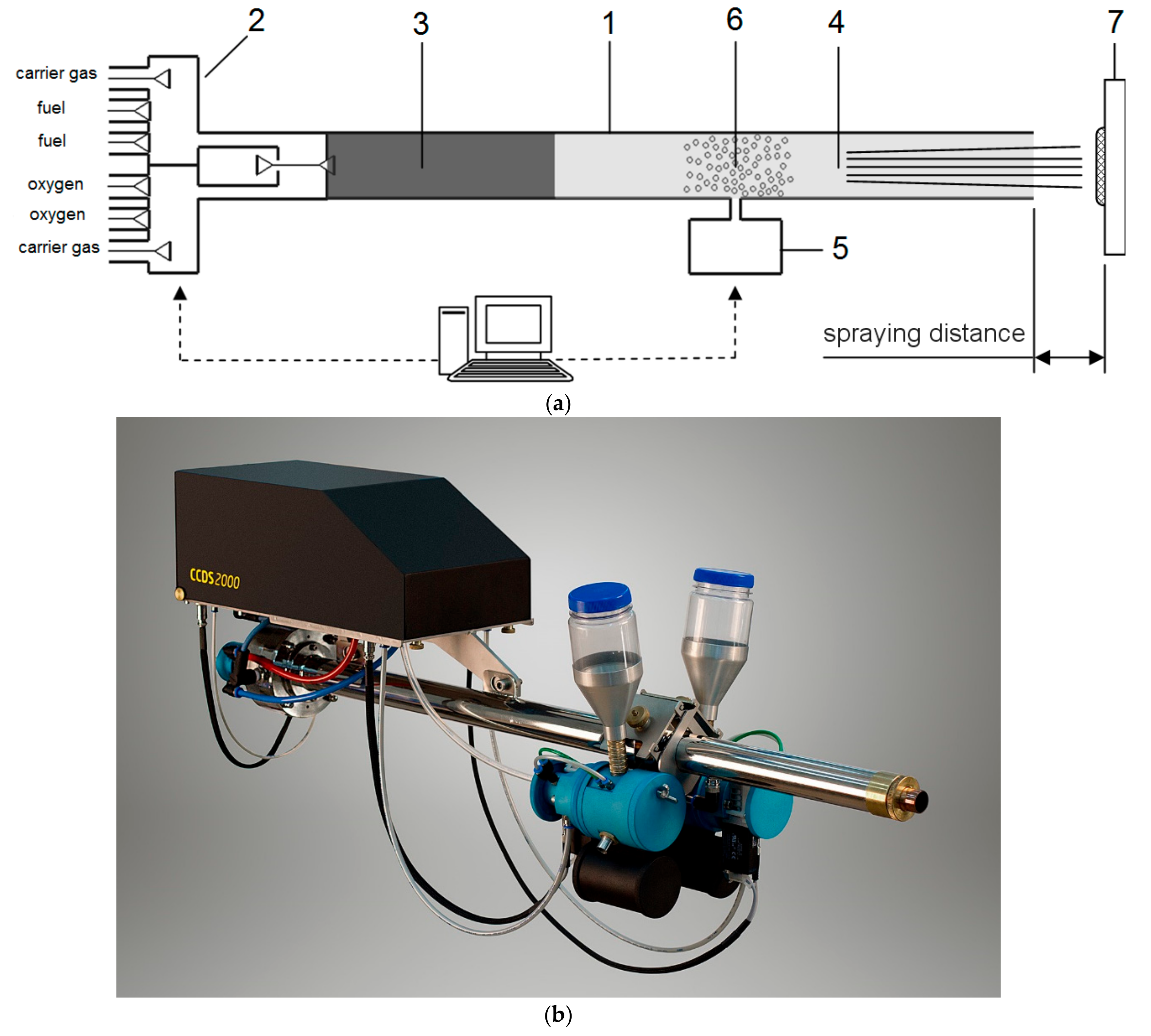
2. Computer-Controlled Detonation Spraying (CCDS): Advanced Facilities of Coating Deposition and Design
3. Mechanisms of Coating Formation by Detonation Spraying
3.1. Studies of the Splat Formation from the Sprayed Particles
3.2. Particle Temperatures and Velocities: Measurements and Calculations
4. Microstructure Control of the CCDS Coatings
4.1. Nanostructured Coatings by Detonation Spraying: Inheritance of the Structure from the Powder/Formation by Rapid Cooling
4.2. Suspension Detonation Spraying—A Novel Method for Obtaining Nanostructured Coatings
4.3. Dispersion of Molten Particles on Impact and Formation of Fine Particulates in a Matrix
4.4. Coatings Made of Alternating Layers by Means of Twin Powder Feeding Systems
4.5. Spraying of Composite Feedstock Powders
5. Chemical Reactions in the Sprayed Materials
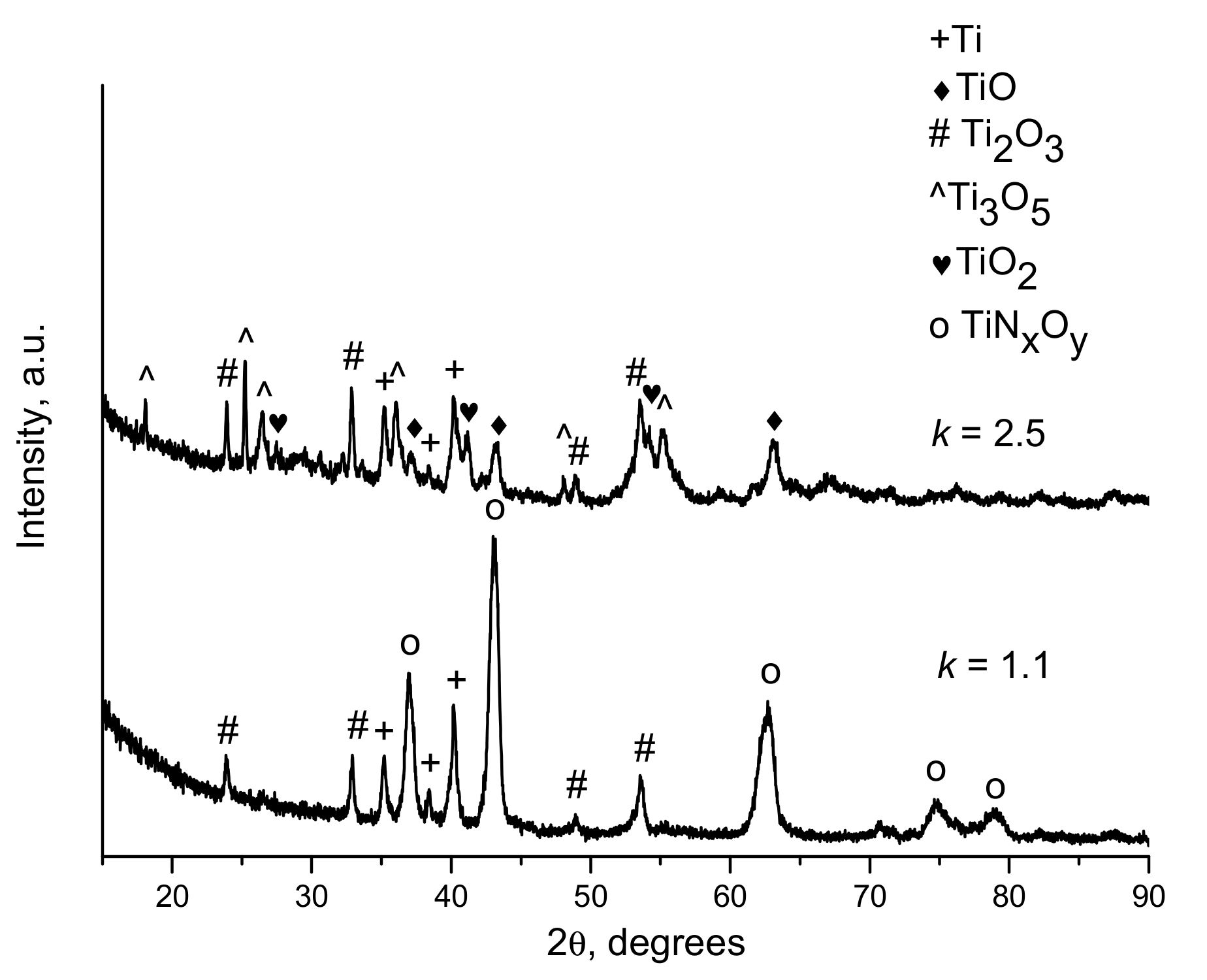
5.1. Oxidation by the Detonation Products
5.2. Reduction by the Detonation Products
5.3. Reactions with the Carrier Gas
5.4. Formation of Carbon and Carbon-Containing Phases in the Coatings in Highly Reducing Conditions
5.5. Reactions between the Phases of Composite Feedstock Powders. Selecting Spraying Conditions to Prevent Chemical Reactions
6. Advanced Applications of Detonation Spraying Enabled by the Capabilities of Computer-Controlled Facilities
Metallization of Plastics
7. Further Research and Outlook
8. Conclusions
Author Contributions
Funding
Acknowledgments
Conflicts of Interest
References
- Poorman, R.M.; Sargent, H.B.; Lamprey, H. Method and Apparatus Utilizing Detonation Waves for Spraying and Other Purposes. U.S. Patent 2,714,553, 2 August 1955. [Google Scholar]
- Astakhov, E.A. Controlling the properties of detonation-sprayed coatings: Major aspects. Powder Metall. Metal Ceram. 2008, 47, 70–79. [Google Scholar] [CrossRef]
- Nikolaev, Y.A.; Vasil’ev, A.A.; Ul’anitskii, B.Y. Gas detonation and its application in engineering and technologies (Review). Combust. Explos. Shock Waves 2003, 39, 382–410. [Google Scholar] [CrossRef]
- Singh, L.; Chawla, V.; Grewal, J.S. A review on detonation gun sprayed coatings. J. Miner. Mater. Charact. Eng. 2012, 11, 243–265. [Google Scholar] [CrossRef]
- Zhao, L.; Lugscheider, E. Reactive plasma spraying of TiAl6V4 alloy. Wear 2002, 253, 1214–1218. [Google Scholar] [CrossRef]
- Valente, T.; Galliano, F.P. Corrosion resistance properties of reactive plasma-sprayed titanium composite coatings. Surf. Coat. Technol. 2000, 127, 86–92. [Google Scholar] [CrossRef]
- Yao, Y.; Wang, Z.; Zhou, Z.; Jiang, S.; Shao, J. Study on reactive atmospheric plasma-sprayed in situ titanium compound composite coating. J. Therm. Spray Technol. 2013, 22, 509–517. [Google Scholar] [CrossRef]
- Suresh Babu, P.; Basu, B.; Sundararajan, G. Processing–structure–property correlation and decarburization phenomenon in detonation sprayed WC–12Co coatings. Acta Mater. 2008, 56, 5012–5026. [Google Scholar] [CrossRef]
- Park, S.Y.; Kim, M.C.; Park, C.G. Mechanical properties and microstructure evolution of the nano WC–Co coatings fabricated by detonation gun spraying with post heat treatment. Mater. Sci. Eng. A 2007, 449–451, 894–897. [Google Scholar] [CrossRef]
- Oliker, V.E.; Sirovatka, V.L.; Timofeeva, I.I.; Gridasova, T.Y.; Hrechyshkin, Y.F. Formation of detonation coatings based in titanium aluminide alloys and aluminum titanate ceramic sprayed from mechanically milled powders Ti-Al. Surf. Coat. Technol. 2006, 200, 3573–3581. [Google Scholar] [CrossRef]
- Senderowski, C.; Bojar, Z.; Wołczyński, W.; Paw1owski, A. Microstructure characterization of D-gun sprayed Fe–Al intermetallic coatings. Intermetallics 2010, 18, 1405–1409. [Google Scholar] [CrossRef]
- Senderowski, C. Nanocomposite Fe-Al intermetallic coating obtained by Gas Detonation Spraying of mlled self-decomposing powder. J. Therm. Spray Technol. 2014, 23, 1124–1134. [Google Scholar] [CrossRef]
- Panas, A.J.; Senderowski, C.; Fikus, B. Thermophysical properties of multiphase Fe-Al intermetallic-oxide ceramic coatings deposited by gas detonation spraying. Thermochim. Acta 2019, 676, 164–171. [Google Scholar] [CrossRef]
- Talako, T.L.; Yakovleva, M.S.; Astakhov, Е.A.; Letsko, A.I. Structure and properties of detonation gun sprayed coatings from the synthesized FeAlSi/Al2O3 powder. Surf. Coat. Technol. 2018, 353, 93–104. [Google Scholar] [CrossRef]
- Fikus, B.; Senderowski, C.; Panas, A.J. Modeling of dynamics and thermal history of Fe40Al intermetallic powder particles under gas detonation spraying using propane–air mixture. J. Therm. Spray Technol. 2019, 28, 346–358. [Google Scholar] [CrossRef]
- Cui, Y.J.; Wang, C.L.; Tang, Z.H. Effect of explosive charge on 65Cr3C2-35NiCr coatings fabricated by D-Gun technology. Mater. Sci. Forum 2016, 852, 1087–1094. [Google Scholar] [CrossRef]
- Sova, A.; Pervushin, D.; Smurov, I. Development of multimaterial coatings by cold spray and gas detonation spraying. Surf. Coat. Technol. 2010, 205, 1108–1114. [Google Scholar] [CrossRef]
- Smurov, I.; Ulianitsky, V. Computer-controlled detonation spraying: A spraying process upgraded to advanced applications. WIT Trans. Eng. Sci. 2011, 71, 265–276. [Google Scholar]
- Ulianitsky, V.; Shtertser, A.; Zlobin, S.; Smurov, I. Computer-controlled detonation spraying: From process fundamentals toward advanced applications. J. Therm. Spray Technol. 2011, 20, 791–801. [Google Scholar] [CrossRef]
- Smurov, I.; Ulianitsky, V. Technology vision: Computer Controlled Detonation Spraying. Surf. Eng. 2011, 27, 557–559. [Google Scholar] [CrossRef]
- Dudina, D.V.; Batraev, I.S.; Ulianitsky, V.Y.; Korchagin, M.A. Possibilities of the Computer-Controlled Detonation Spraying method: A chemistry viewpoint. Ceram. Int. 2014, 40, 3253–3260. [Google Scholar] [CrossRef]
- Ulianitsky, V.Y.; Shtertser, A.A.; Zlobin, S.B.; Kiryakin, A.L. Method for Detonating Application of Coatings and Apparatus for Implementing thereof. Patent RU 2,329,104, 30 August 2006. [Google Scholar]
- Ulianitsky, V.Y.; Kiryakin, A.L.; Shtertser, A.A.; Zlobin, S.B. Detonation Spraying Unit. Patent RU 2,399,430, 17 February 2009. [Google Scholar]
- Ulianitsky, V.Y.; Shtertser, A.A.; Zlobin, S.B. Detonation Spraying Unit Barrel. Patent RU 2,404,860, 27 November 2010. [Google Scholar]
- Ulianitsky, V.; Batraev, I.; Dudina, D.; Smurov, I. Enhancing the properties of WC/Co detonation coatings using two-component fuels. Surf. Coat. Technol. 2017, 318, 244–249. [Google Scholar] [CrossRef]
- Jackson, J.E. Fuel-Oxidant Mixture for Detonation Gun Flame-Plating. EP Patent 0,313,176, 26 April 1989. [Google Scholar]
- Gavrilenko, T.; Nikolaev, Y. Calculation of detonation gas spraying. Combust. Explos. Shock Waves 2007, 43, 724–731. [Google Scholar] [CrossRef]
- Kuchumova, I.D.; Batraev, I.S.; Ulianitsky, V.Y.; Shtertser, A.A.; Gerasimov, K.B.; Ukhina, A.V.; Bulina, N.V.; Bataev, I.A.; Koga, G.Y.; Guo, Y.; et al. Formation of metallic glass coatings by detonation spraying of a Fe66Cr10Nb5B19 powder. Metals 2019, 9, 846. [Google Scholar] [CrossRef]
- Ulianitsky, V.Y.; Dudina, D.V.; Batraev, I.S.; Kovalenko, A.I.; Bulina, N.V.; Bokhonov, B.B. Detonation spraying of titanium and formation of coatings with spraying atmosphere-dependent phase composition. Surf. Coat. Technol. 2015, 261, 174–180. [Google Scholar] [CrossRef]
- Dudina, D.V.; Batraev, I.S.; Ulianitsky, V.Y.; Bulina, N.V.; Korchagin, M.A.; Lomovsky, O.I. Detonation spraying of Ti-Al intermetallics: Phase and microstructure development of the coatings. Mater. Manuf. Proc. 2015, 30, 724–729. [Google Scholar] [CrossRef]
- Gavrilenko, T.P.; Nikolaev, Y.A.; Prokhorov, E.S.; Ul’yanitskii, V.Y. Mechanisms of coating formation with flame spraying. Combust. Explos. Shock Waves 1990, 26, 228–238. [Google Scholar] [CrossRef]
- Ulianitsky, V.Y.; Batraev, I.S.; Shtertser, A.A.; Dudina, D.V.; Bulina, N.V.; Smurov, I. Detonation spraying behaviour of refractory metals: Case studies for Mo and Ta-based powders. Adv. Powder Technol. 2018, 29, 1859–1864. [Google Scholar] [CrossRef]
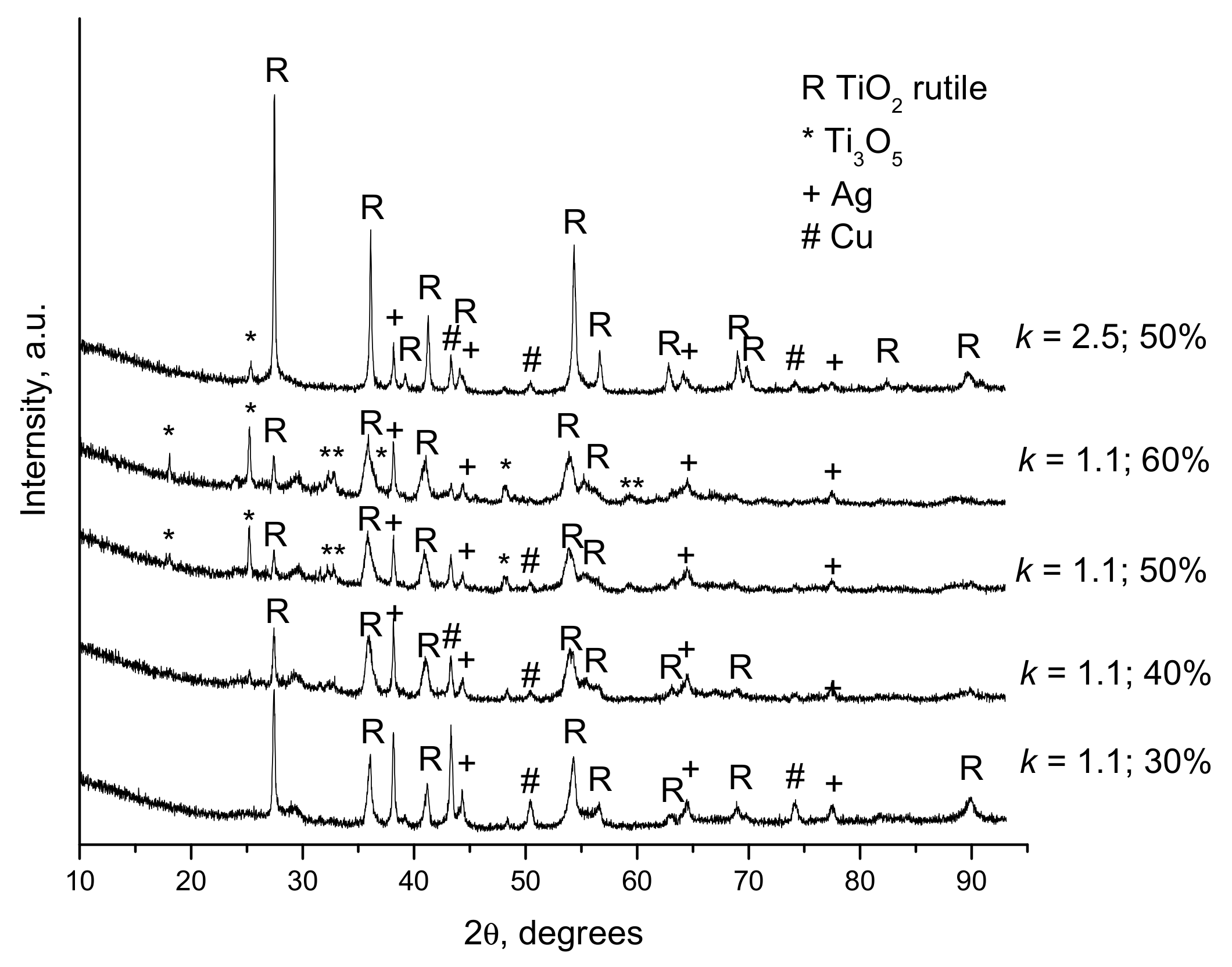
- Dudina, D.V.; Zlobin, S.B.; Bulina, N.V.; Bychkov, A.L.; Korolyuk, V.N.; Ulianitsky, V.Y.; Lomovsky, O.I. Detonation spraying of TiO2-2.5vol.%Ag powders in a reducing atmosphere. J. Eur. Ceram. Soc. 2012, 32, 815–821. [Google Scholar] [CrossRef]
- Dudina, D.V.; Zlobin, S.B.; Ulianitsky, V.Y.; Lomovsky, O.I.; Bulina, N.V.; Bataev, I.A.; Bataev, V.A. Detonation spraying of TiO2-Ag: Controlling the phase composition and microstructure of the coatings. Ceram. Trans. 2012, 237, 161–169. [Google Scholar]
- Viswanathan, V.; Laha, T.; Balani, K.; Agarwal, A.; Seal, S. Challenges and advances in nanocomposite processing techniques. Mater. Sci. Eng. R 2006, 54, 121–285. [Google Scholar] [CrossRef]
- Fauchais, P.; Montavon, G.; Bertrand, G. From powders to thermally sprayed coatings. J. Therm. Spray Technol. 2010, 19, 56–80. [Google Scholar] [CrossRef]
- Laha, T.; Agarwal, A.; McKechnie, T. Forming nanostructured hypereutectic aluminum via high-velocity oxyfuel spray deposition. JOM 2004, 56, 54–56. [Google Scholar] [CrossRef]
- Fauchais, P.; Montavon, G.; Lima, R.S.; Marple, B.R. Engineering a new class of thermal spray nano-based microstructures from agglomerated nanostructure particles, suspensions and solutions: An invited review. J. Phys. D Appl. Phys. 2001, 44, 093001. [Google Scholar] [CrossRef]
- Lomovsky, O.I.; Dudina, D.V.; Ulianitsky, V.Y.; Zlobin, S.B.; Kosarev, V.F.; Klinkov, S.V.; Korchagin, M.A.; Rozhkov, I.A.; Kwon, D.H.; Kim, J.S.; et al. Formation of cold and detonation sprayed coatings from TiB2-Cu nanocomposite powders produced by mechanical milling. Chem. Sustain. Dev. 2007, 15, 197–201. [Google Scholar]
- Lomovsky, O.I.; Dudina, D.V.; Ulianitsky, V.Y.; Zlobin, S.B.; Kosarev, V.F.; Klinkov, S.V.; Korchagin, M.A.; Kwon, D.H.; Kim, J.S.; Kwon, Y.S. Cold and detonation spraying of TiB2-Cu nanocomposites. Mater. Sci. Forum 2007, 534, 1373–1376. [Google Scholar] [CrossRef]
- Dudina, D.V.; Batraev, I.S.; Ulianitsky, V.Y.; Bulina, N.V.; Korchagin, M.A.; Bataev, I.A.; Jorge, A.M., Jr. Formation routes of nanocomposite coatings in detonation spraying of Ti3SiC2-Cu powders. J. Therm. Spray Technol. 2014, 23, 1116–1123. [Google Scholar] [CrossRef]
- Dudina, D.V.; Batraev, I.S.; Ulianitsky, V.Y.; Korchagin, M.A.; Golubkova, G.V.; Abramov, S.Y.; Lomovsky, O.I. Control of interfacial interaction during detonation spraying of Ti3SiC2–Cu composites. Inorg. Mater. 2014, 50, 35–39. [Google Scholar] [CrossRef]
- Dudina, D.V.; Ulianitsky, V.Y.; Batraev, I.S.; Korchagin, M.A.; Mali, V.I.; Anisimov, A.G.; Lomovsky, O.I. Interparticle interactions during consolidation of Ti3SiC2-Cu powders influenced by preliminary mechanical milling. Chem. Sustain. Dev. 2014, 22, 31–37. [Google Scholar]
- Kassner, H.; Siegert, R.; Hathiramani, D.; Vassen, R.; Stoever, D. Application of suspension plasma spraying (SPS) for manufacture of ceramic coatings. J. Therm. Spray Technol. 2008, 17, 115–123. [Google Scholar] [CrossRef]
- Shtertser, A.A.; Ulyanitskii, V.Y.; Rybin, D.K. Suspension detonation spraying of ceramic coatings. Combust. Explos. Shock Waves 2019, 55, 483–490. [Google Scholar] [CrossRef]
- Sobolev, V.V.; Guilemany, J.M. Formation of splats during thermal spraying of composite powder particles. Mater. Lett. 2000, 42, 46–51. [Google Scholar] [CrossRef]
- Dudina, D.V.; Korchagin, M.A.; Zlobin, S.B.; Ulianitsky, V.Y.; Lomovsky, O.I.; Bulina, N.V.; Bataev, I.A.; Bataev, V.A. Compositional variations in the coatings formed by detonation spraying of Ti3Al at different O2/C2H2 ratios. Intermetallics 2012, 29, 140–146. [Google Scholar] [CrossRef]
- Shtertser, A.A.; Ulianitsky, V.Y.; Batraev, I.S.; Gromilov, S.A.; Okotrub, A.V.; Saprykin, A.I. Diagnostics of the structure and composition of ultrafine carbon obtained by detonation. J. Struct. Chem. 2014, 55, 986–989. [Google Scholar] [CrossRef]
- Batraev, I.S.; Vasil’ev, A.A.; Ul’yanitskii, V.Y.; Shtertser, A.A.; Rybin, D.K. Investigation of gas detonation in over-rich mixtures of hydrocarbons with oxygen. Combust. Explos. Shock Waves 2018, 54, 207–215. [Google Scholar] [CrossRef]
- Shtertser, A.A.; Ulianitsky, V.Y.; Batraev, I.S.; Rybin, D.K. Production of nanoscale detonation carbon using a pulse gas-detonation device. Tech. Phys. Lett. 2018, 44, 395–397. [Google Scholar] [CrossRef]
- Batraev, I.S.; Vasil’ev, A.A.; Pinaev, A.V.; Ulianitsky, V.Y.; Shtertser, A.A.; Likholobov, V.A.; Shaitanov, A.G.; Surovkin, Y.V.; Rybin, D.K. Method for Obtaining Nanocarbon. Patent RU 2,641,829, 9 August 2016. [Google Scholar]
- Shtertser, A.A.; Rybin, D.K.; Ulianitsky, V.Y.; Park, W.; Datekyu, M.; Wada, T.; Kato, H. Characterization of nanoscale detonation carbon produced in a pulse gas-detonation device. Diam. Relat. Mater. 2020, 101, 107553. [Google Scholar] [CrossRef]
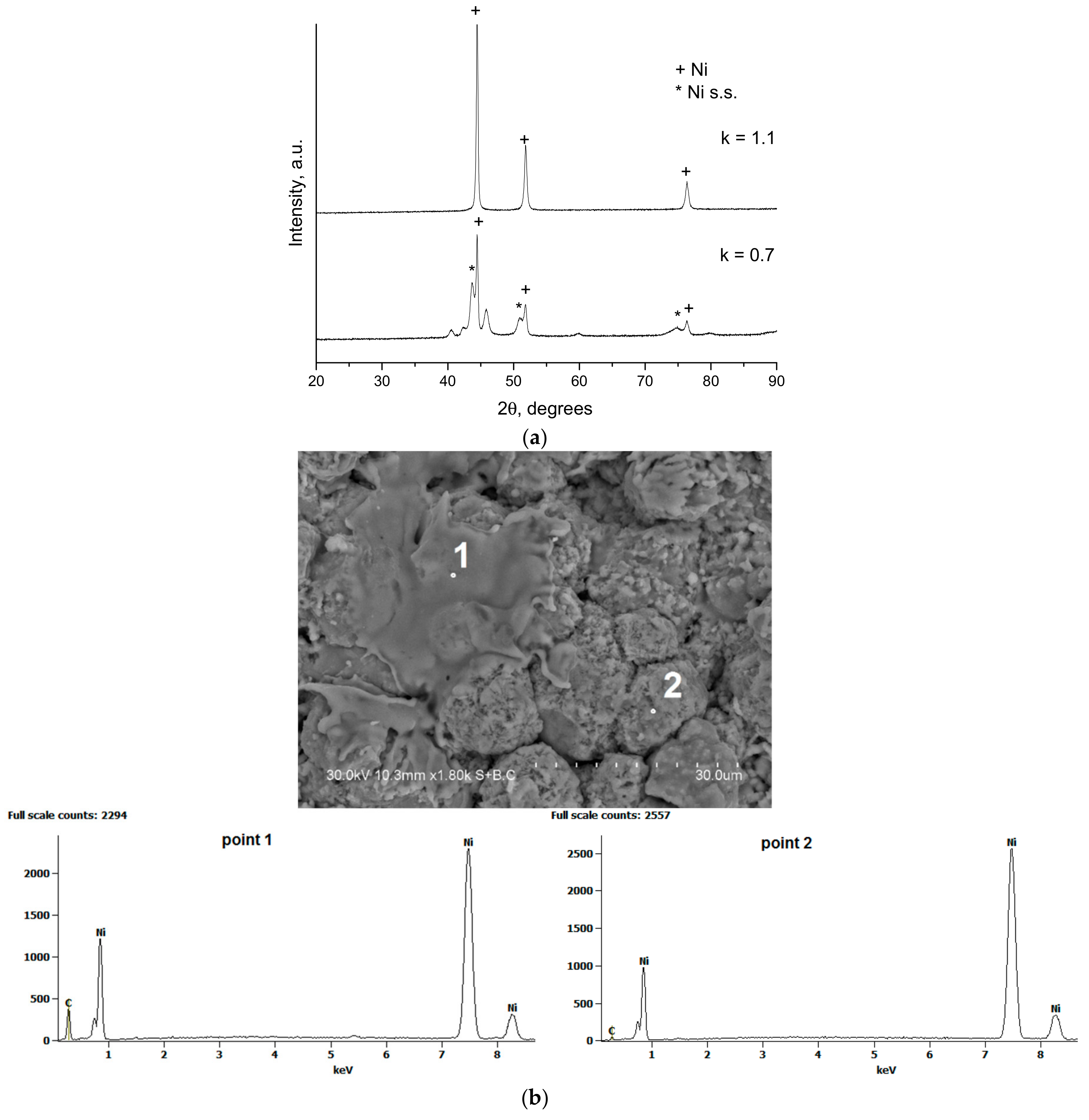
- Ulianitsky, V.Y.; Dudina, D.V.; Batraev, I.S.; Rybin, D.K.; Bulina, N.V.; Ukhina, A.V.; Bokhonov, B.B. The influence of the in-situ formed and added carbon on the formation of metastable Ni-based phases during detonation spraying. Mater. Lett. 2016, 181, 127–131. [Google Scholar] [CrossRef]
- Ulianitsky, V.Y.; Shtertser, A.A.; Zlobin, S.B.; Ostrer, S.G. Procedure for metallisation of part of polymer material by detonation spraying. Patent RU 2,425,912, 4 August 2009. [Google Scholar]
- Shtertser, A.; Muders, C.; Veselov, S.; Zlobin, S.; Ulianitsky, V.; Jiang, X.; Bataev, V. Computer controlled detonation spraying of WC/Co coatings containing MoS2 solid lubricant. Surf. Coat. Technol. 2012, 206, 4763–4770. [Google Scholar] [CrossRef]
- Sadykov, V.; Sobyanin, V.; Mezentseva, N.; Alikina, G.; Vostrikov, Z.; Fedorova, Y.; Pelipenko, V.; Usoltsev, V.; Tikhov, S.; Salanov, A.; et al. Transformation of CH4 and liquid fuels into syngas on monolithic catalysts. Fuel 2010, 89, 1230–1240. [Google Scholar] [CrossRef]
- Ulianitsky, V.; Shtertser, A.; Sadykov, V.; Smurov, I. Development of catalytic converters using detonation spraying. Mater. Manuf. Process. 2016, 31, 1433–1438. [Google Scholar] [CrossRef]
- Gadow, R.; Killiger, A.; Stiegler, N. Hydroxyapatite coatings for biomedical applications deposited by different thermal spray techniques. Surf. Coat. Technol. 2010, 205, 1157–1164. [Google Scholar] [CrossRef]
- Toma, F.-L.; Potthoff, A.; Berger, L.-M.; Leyens, C. Demands, potentials, and economic aspects of thermal spraying with suspensions: A critical review. J. Therm. Spray Technol. 2015, 24, 1143–1152. [Google Scholar] [CrossRef]
- Pawlowski, L. Suspension and solution thermal spray coatings. Surf. Coat. Technol. 2009, 203, 2807–2829. [Google Scholar] [CrossRef]
- Dudina, D.V. Application of a spark plasma sintering facility for the heat treatment of compact and powder materials. Inorg. Mater. 2017, 53, 658–663. [Google Scholar] [CrossRef]
- Saphronov, V.; Shishkovsky, I. Laser annealing for gas-dynamical spraying of HA coating upon a titanium surface. Crystals 2015, 5, 447–457. [Google Scholar] [CrossRef]
- Kamal, S.; Jayaganthan, R.; Prakash, S.; Kumar, S. Hot corrosion behavior of detonation gun sprayed Cr3C2–NiCr coatings on Ni and Fe-based superalloys in Na2SO4–60%V2O5 environment at 900 °C. J. Alloys Compd. 2008, 463, 358–372. [Google Scholar] [CrossRef]
- Kamal, S.; Jayaganthan, R.; Prakash, S. Mechanical and microstructural characteristics of detonation gun sprayed NiCrAlY + 0.4 wt% CeO2 coatings on superalloys. Mater. Chem. Phys. 2010, 122, 262–268. [Google Scholar] [CrossRef]
- Gao, Y.; Gao, C.; Gao, J.; Cai, L. Comparison of the mechanical and wear-resistant properties of WC-13Ni4Cr and WC-10Co4Cr coatings obtained by detonation spraying. J. Therm. Spray Technol. 2019, 28, 851–861. [Google Scholar]
- Wang, Q.; Sun, Q.; Zhang, M.-X.; Niu, W.-J.; Tang, C.-B.; Wang, K.-S.; Rui, X.; Zhai, L.; Wang, L. The influence of cold and detonation thermal spraying processes on the microstructure and properties of Al-based composite coatings on Mg alloy. Surf. Coat. Technol. 2018, 352, 627–633. [Google Scholar] [CrossRef]
- Xie, L.; Xiong, X.; Zeng, Y.; Wang, Y. The wear properties and mechanism of detonation sprayed iron-based amorphous coating. Surf. Coat. Technol. 2019, 366, 146–155. [Google Scholar] [CrossRef]


| Components | ai | ||
|---|---|---|---|
| k = 1.1 | k = 1.5 | k = 2.0 | |
| O | 0.009 | 0.064 | 0.112 |
| O2 | – | 0.015 | 0.065 |
| H | 0.215 | 0.160 | 0.102 |
| H2 | 0.165 | 0.094 | 0.053 |
| OH | 0.013 | 0.070 | 0.106 |
| H2O | 0.014 | 0.060 | 0.083 |
| CO | 0.579 | 0.503 | 0.411 |
| CO2 | 0.005 | 0.033 | 0.069 |
| Explosive Charge, % | Particle Size, µm | Velocity, m s−1 | Temperature, K | * T/Tm (TiO2) | ** T/Tm (Ag) |
|---|---|---|---|---|---|
| 30 | 20 | 554 | 782 | 0.37 | 0.63 |
| 40 | 431 | 1315 | 0.62 | 1.06 | |
| 60 | 364 | 1124 | 0.53 | 0.91 | |
| 40 | 20 | 614 | 1606 | 0.76 | 1.30 |
| 40 | 514 | 1703 | 0.80 | 1.38 | |
| 60 | 430 | 1400 | 0.66 | 1.13 | |
| 60 | 20 | 678 | 2646 | 1.25 | boiling point reached |
| 40 | 534 | 2123 | 1.00 | 1.72 | |
| 60 | 417 | 2039 | 0.96 | 1.65 |
| k | Spraying Distance, mm | Explosive Charge, % | Phases of the Coatings |
|---|---|---|---|
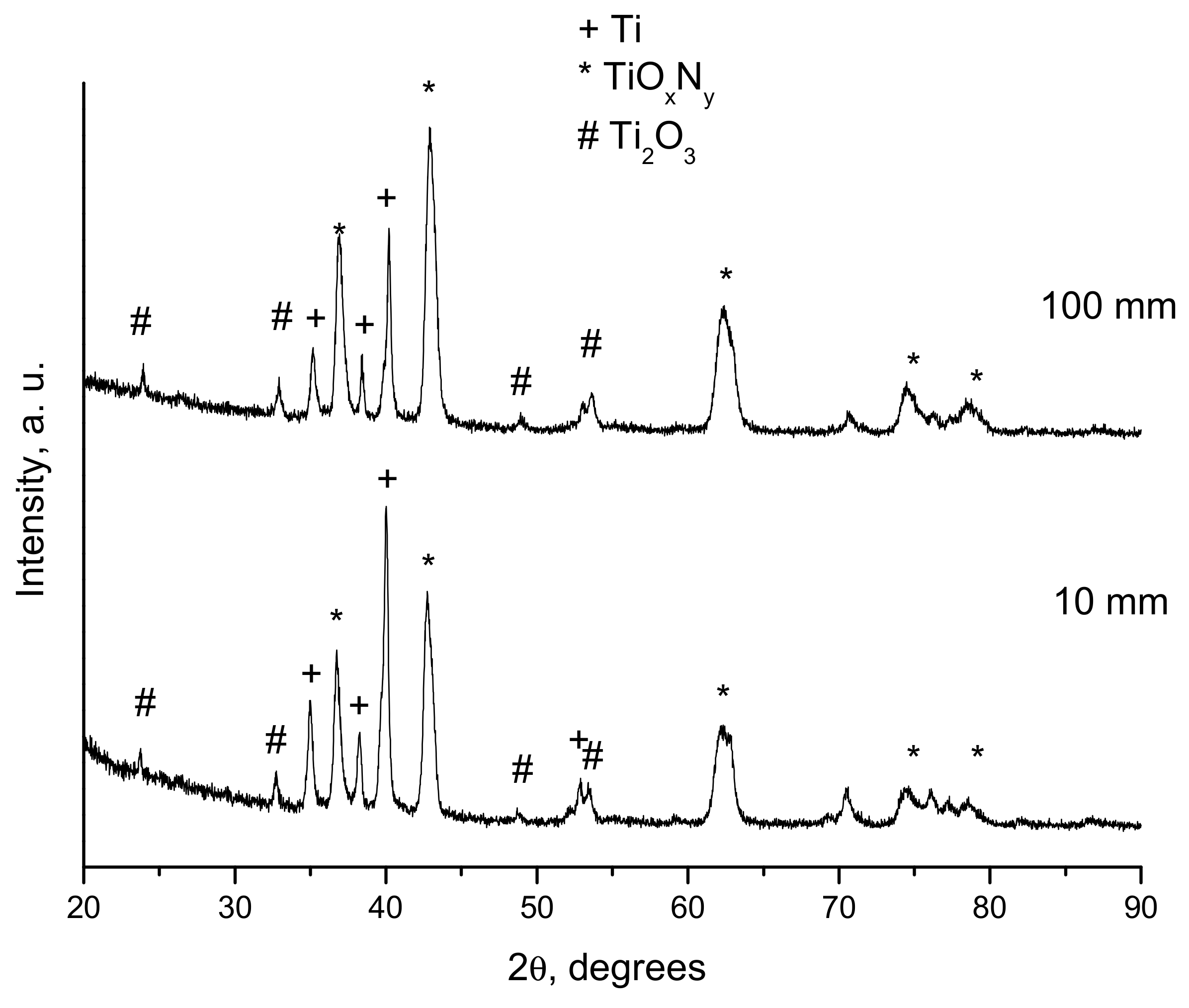
| 1.1 | 10 | 25 | Ti, TiNxOy, Ti2O3 |
| 1.1 | 100 | 25 | Ti, TiNxOy, Ti2O3 |
| 1.1 | 100 | 30 | Ti, TiNxOy, Ti2O3 |
| 1.5 | 10 | 25 | Ti, TiO, Ti2O3, Ti3O5 |
| 1.5 | 100 | 25 | Ti, TiO, Ti2O3, Ti3O5 |
| 2.5 | 100 | 30 | Ti, TiO, Ti2O3, Ti3O5, TiO2 |
© 2019 by the authors. Licensee MDPI, Basel, Switzerland. This article is an open access article distributed under the terms and conditions of the Creative Commons Attribution (CC BY) license (http://creativecommons.org/licenses/by/4.0/).
Share and Cite
Ulianitsky, V.Y.; Dudina, D.V.; Shtertser, A.A.; Smurov, I. Computer-Controlled Detonation Spraying: Flexible Control of the Coating Chemistry and Microstructure. Metals 2019, 9, 1244. https://doi.org/10.3390/met9121244
Ulianitsky VY, Dudina DV, Shtertser AA, Smurov I. Computer-Controlled Detonation Spraying: Flexible Control of the Coating Chemistry and Microstructure. Metals. 2019; 9(12):1244. https://doi.org/10.3390/met9121244
Chicago/Turabian StyleUlianitsky, Vladimir Yu., Dina V. Dudina, Alexandr A. Shtertser, and Igor Smurov. 2019. "Computer-Controlled Detonation Spraying: Flexible Control of the Coating Chemistry and Microstructure" Metals 9, no. 12: 1244. https://doi.org/10.3390/met9121244
APA StyleUlianitsky, V. Y., Dudina, D. V., Shtertser, A. A., & Smurov, I. (2019). Computer-Controlled Detonation Spraying: Flexible Control of the Coating Chemistry and Microstructure. Metals, 9(12), 1244. https://doi.org/10.3390/met9121244