Application of Cold Metal Transfer Welding for High Pressure Die Casting Mold Restoration


Abstract
1. Introduction
2. Materials and Methods
Immersion Test
3. Results and Discussion
3.1. Microstructure Characterization
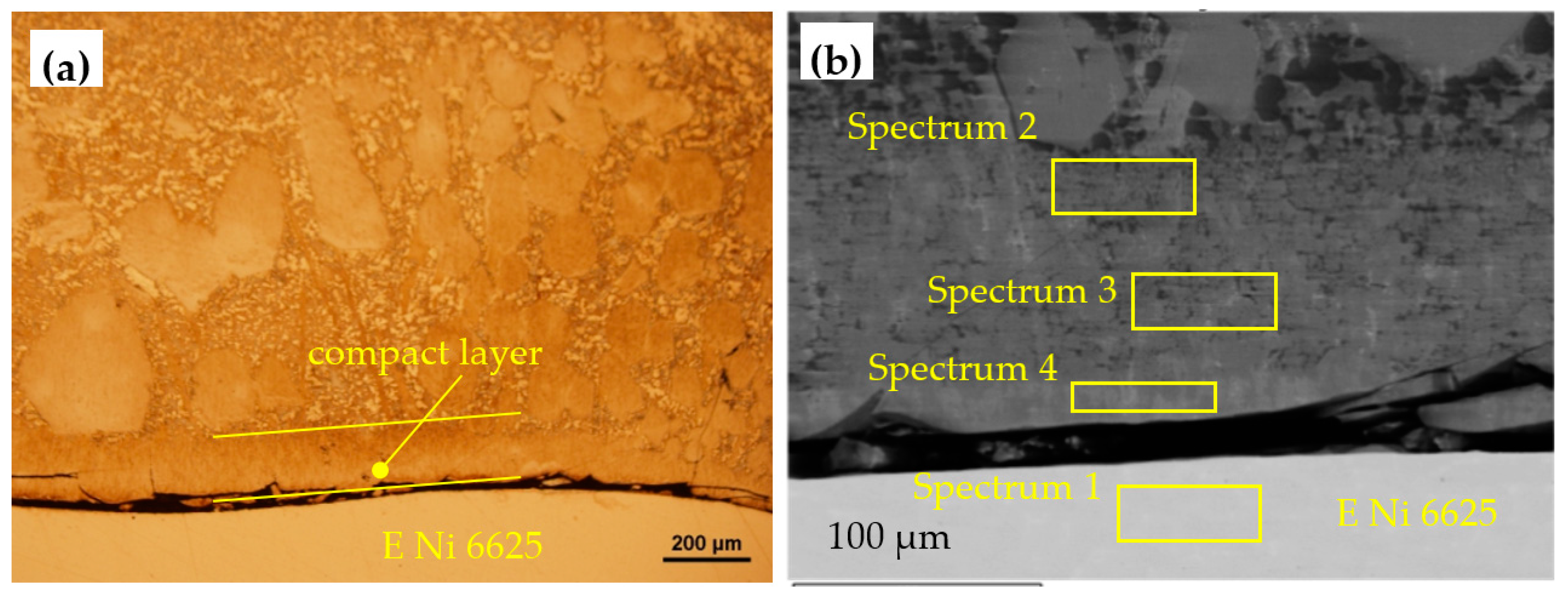
3.1.1. Microstructure of E Ni 6625 Welded Clad
3.1.2. Microstructure of E 18 8 Mn B 2 2 Welded Clad
3.2. Immersion Test
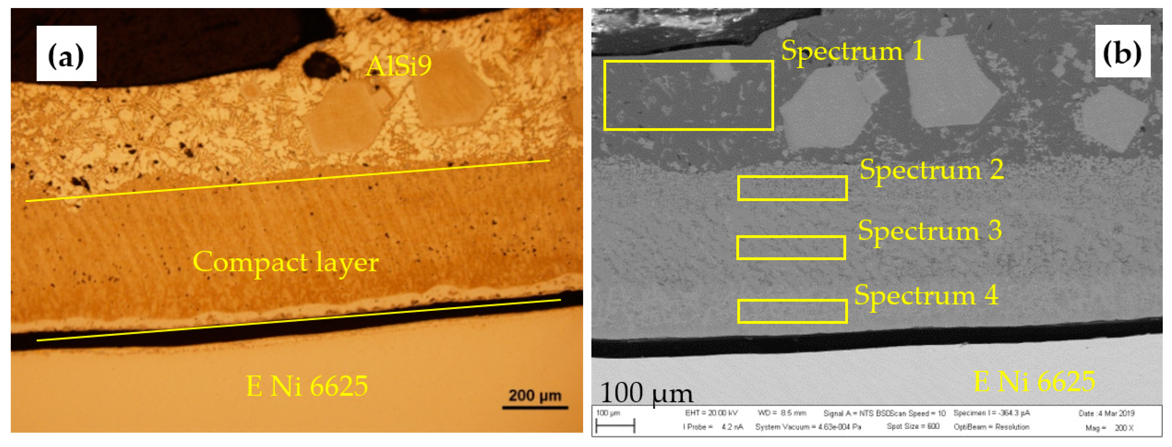
3.2.1. Immersion Test of E Ni 6625
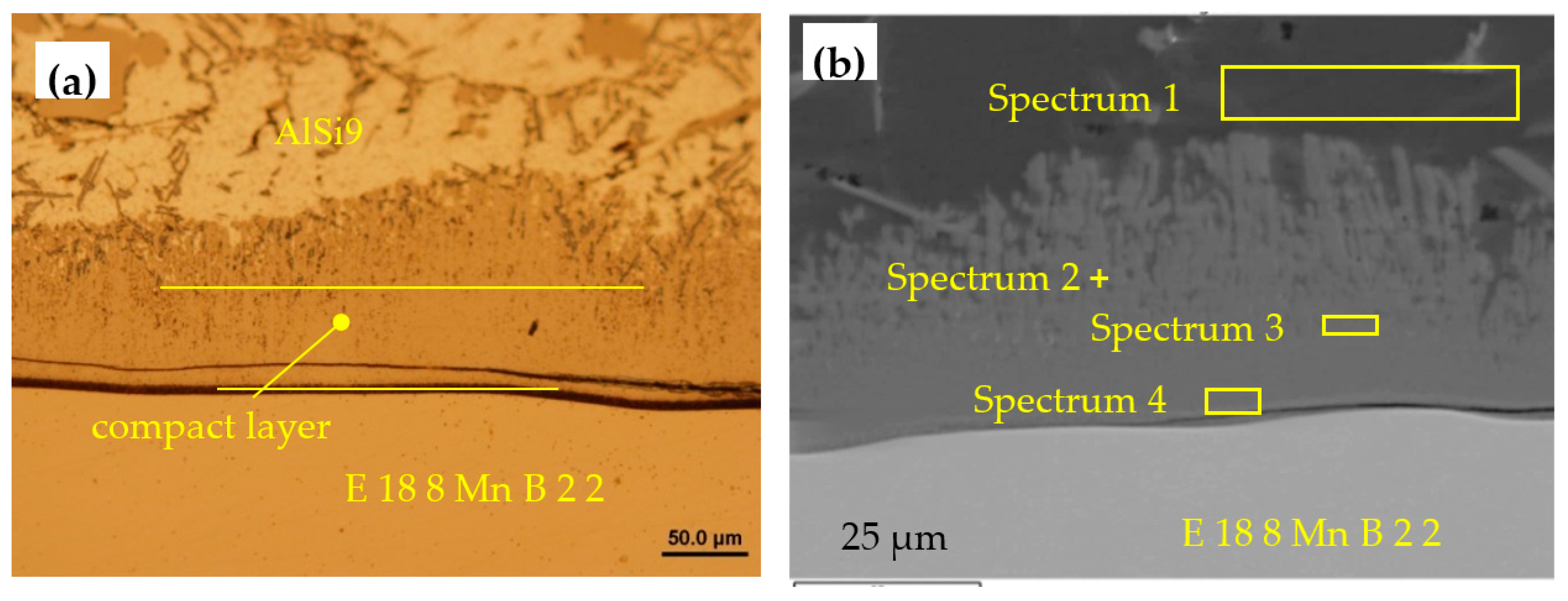
3.2.2. Immersion Test of E 18 8 Mn B 2 2
3.2.3. Immersion Test of the Base Material
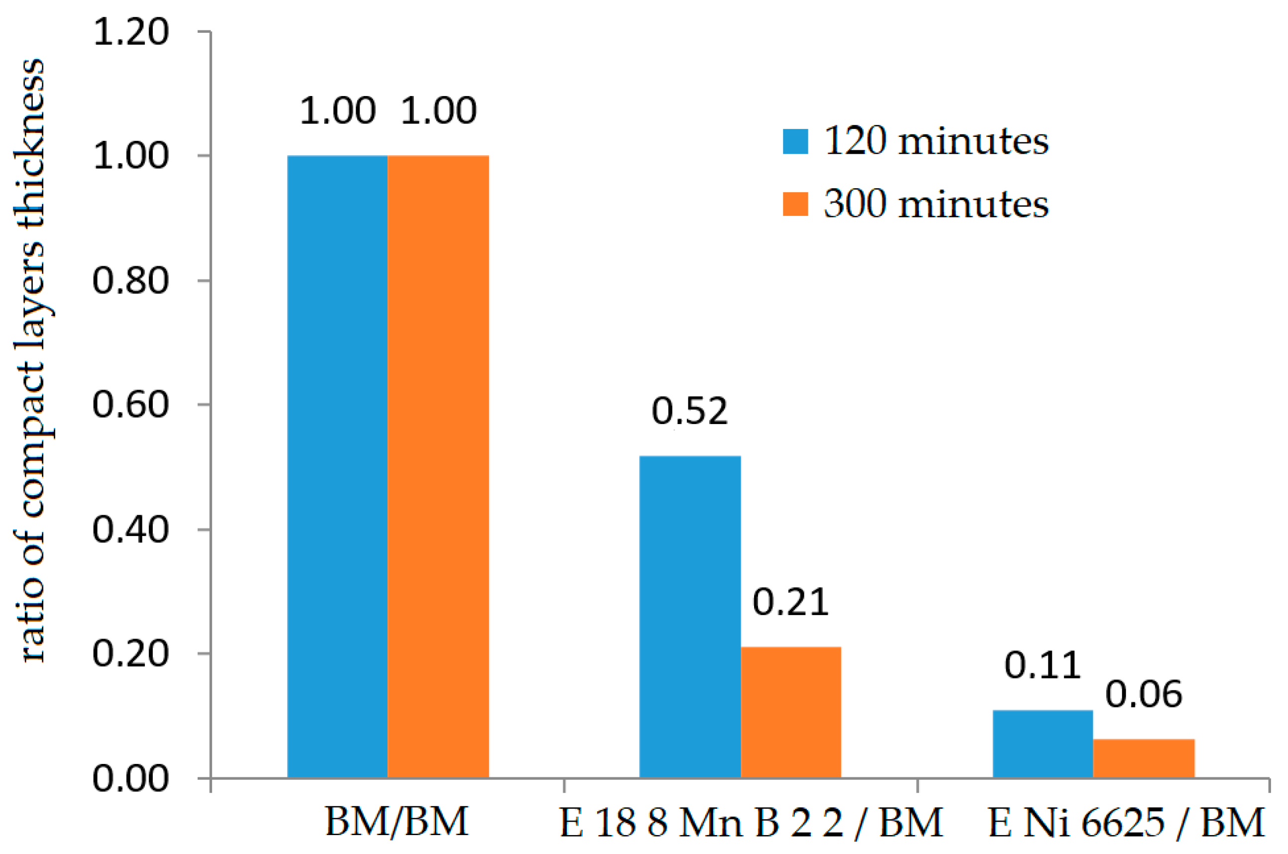
3.3. Measurement of Compact Layer Thickness
4. Conclusions
Author Contributions
Funding
Conflicts of Interest
References
- Hirsch, J. Recent development in aluminium for automotive applications. Trans. Nonferr. Met. Soc. China 2014, 24, 1995–2002. [Google Scholar] [CrossRef]
- Pickin, C.G.; Williams, S.W.; Lunt, M. Characterisation of the cold metal transfer (CMT) process and its application for low dilution cladding. J. Mater. Process. Technol. 2011, 211, 496–502. [Google Scholar] [CrossRef]
- Jhavar, S.; Paul, C.P.; Jain, N.K. Causes of failure and repairing options for dies and molds: A review. Eng. Fail. Anal. 2013, 34, 519–535. [Google Scholar] [CrossRef]
- Chander, S.; Chawla, V. Failure of hot forging dies—An updated perspective. Mater. Today Proc. 2017, 4, 1147–1157. [Google Scholar] [CrossRef]
- Chen, C.; Wang, Y.; Ou, H.; He, Y.; Tang, X. A review on remanufacture of dies and moulds. J. Clean. Prod. 2014, 64, 13–23. [Google Scholar] [CrossRef]
- Taylan, A.; Blaine, L.; Yen, Y.C. Manufacturing of dies and molds. CIRP Ann. 2001, 50, 404–422. [Google Scholar] [CrossRef]
- Lin, J.; Carrera, S.; Kunrath, A.O.; Zhong, D.; Myers, S.; Mishra, B.; Ried, P.; Moore, J.J. Design methodology for optimized die coatings: The case for aluminum pressure die-casting. Surf. Coat. Technol. 2006, 201, 2930–2941. [Google Scholar] [CrossRef]
- Joshi, V.; Srivastava, A.; Shivpuri, R.; Rolinski, E. Investigating ion nitriding for the reduction of dissolution and soldering in die-casting shot sleeves. Surf. Coat. Technol. 2003, 163–164, 668–673. [Google Scholar] [CrossRef]
- Psyllaki, P.; Kefalonikas, G.; Pantazopoulos, G.; Antoniou, S.; Sideris, J. Microstructure and tribological behaviour of liquid nitrocarburised tool steels. Surf. Coat. Technol. 2002, 162, 67–78. [Google Scholar] [CrossRef]
- Suarez, S.A.; Suarez, A.M.; Preciado, W.T. Arc welding procedures on steels for molds and dies. Procedia Eng. 2015, 100, 584–591. [Google Scholar] [CrossRef]
- Xu, X.; Mi, G.; Xiong, L.; Jiang, P.; Shao, X.; Wang, C. Morphologies, microstructures and properties of TiC particle reinforced Inconel 625 coatings obtained by laser cladding with wire. J. Alloy. Compd. 2018, 740, 16–27. [Google Scholar] [CrossRef]
- Prakash, K.; Santanu, P.; Ramesh, S.; Wenyi, Y. Experimental characterization of laser cladding of CPM 9V on H13 tool steel for die repair applications. J. Manuf. Process. 2015, 20, 492–499. [Google Scholar] [CrossRef]
- Santanu, P.; Ramesh, S.; Wenyi, Y. Thermal model for additive restoration of mold steels using crucible steel. J. Manuf. Process. 2016, 24, 346–354. [Google Scholar] [CrossRef]
- Santanu, P.; Khushahal, T.; Ramesh, S.; Indradev, S.; Wenyi, Y. Experimental characterization of clad microstructure and its correlation with residual stresses. Procedia Manuf. 2017, 10, 804–818. [Google Scholar] [CrossRef]
- Imoudu, N.E.; Ayele, Y.Z.; Barabadi, A. The characteristic of cold metal transfer (CMT) and its application for cladding. In Proceedings of the International Conference on Industrial Engineering and Engineering Management IEEM, Singapore, 10–13 December 2017; pp. 1883–1887. [Google Scholar]
- Pisu, T.M.; Vas, A.; Magyari, M.; Iordache, A. Research on cladding (CMTMIG, WIG arc mechanized pulse) for molds used for casting. Metal. Int. 2013, 18, 89–94. [Google Scholar]
- Chen, M.; Zhang, D.; Wu, C. Current waveform effects on CMT welding of mild steel. J. Mater. Process. Technol. 2017, 243, 395–404. [Google Scholar] [CrossRef]
- Pang, J.; Hu, S.; Shen, J.; Wang, P.; Liang, Y. Arc characteristics and metal transfer behavior of CMT + P welding process. J. Mater. Process. Technol. 2016, 238, 212–217. [Google Scholar] [CrossRef]
- Selvi, S.; Vishvaksenan, A.; Rajasekar, E. Cold metal transfer (CMT) technology—An overview. Def. Technol. 2018, 14, 28–44. [Google Scholar] [CrossRef]
- Gungor, B.; Kaluc, E.; Taban, E.; Sik, A. Mechanical and microstructural properties of robotic COLD METAL TRANSFER (CMT) welded 5083-H111 and 6082-T651 aluminum alloys. Mater. Des. 2014, 54, 207–211. [Google Scholar] [CrossRef]
- Cong, B.; Ouyang, R.; Qi, B.; Ding, J. Influence of cold metal transfer process and its heat input on weld bead geometry and porosity of aluminum-copper alloy welds. Rare Met. Mater. Eng. 2016, 45, 606–611. [Google Scholar] [CrossRef]
- Liang, Y.; Shen, J.; Hu, S.; Wang, H.; Pang, J. Effect of TIG current on microstructural and mechanical properties of 6061-T6 aluminium alloy joints by TIG–CMT hybrid welding. J. Mater. Process. Technol. 2018, 255, 161–174. [Google Scholar] [CrossRef]
- Sun, Q.J.; Li, J.Z.; Liu, Y.B.; Li, B.P.; Xu, P.W.; Feng, J.C. Microstructural characterization and mechanical properties of Al/Ti joint welded by CMT method—Assisted hybrid magnetic field. Mater. Des. 2017, 116, 316–324. [Google Scholar] [CrossRef]
- Lutterotti, L.; Bortolotti, M.; Ischia, G.; Lonardelli, I.; Wenk, H.R. Rietveld texture analysis from diffraction images. Z. Kristallogr. Suppl. 2007, 26, 125–130. [Google Scholar] [CrossRef]
- Satyanarayana, D.V.V.; Prasad, N.E. Nickel-based superalloys. In Aerospace Materials and Material Technologies; Prasad, N., Wanhill, R., Eds.; Indian Institute of Metals Series; Springer: Singapore, 2017; pp. 199–228. [Google Scholar] [CrossRef]
- Xing, X.; Di, X.; Wang, B. The effect of post-weld heat treatment temperature on the microstructure of Inconel 625 deposited metal. J. Alloy. Compd. 2014, 593, 110–116. [Google Scholar] [CrossRef]
- Dupont, J.N.; Lippold, J.C.; Kiser, S.D. Welding Metallurgy and Weldability of Nickel-Base Alloys, 1st ed.; John Wiley & Sons, Inc.: Hoboken, NJ, USA, 2009; p. 440. [Google Scholar] [CrossRef]
- Rajani, H.R.Z.; Torkamani, H.; Sharbati, M.; Raygan, S. Corrosion resistance improvement in Gas Tungsten Arc Welded 316L stainless steel joints through controlled preheat treatment. Mater. Des. 2012, 34, 51–57. [Google Scholar] [CrossRef]
- Lippold, J.C.; Kotecki, D.J. Welding Metallurgy and Weldability of Stainless Steels, 1st ed.; John Wiley & Sons, Inc.: Hoboken, NJ, USA, 2005; p. 367. [Google Scholar]
- Feng, Y.; Luo, Z.; Liu, Z.; Li, Y.; Luo, Y.; Huang, Y. Keyhole gas tungsten arc welding of AISI 316L stainless steel. Mater. Des. 2015, 85, 24–31. [Google Scholar] [CrossRef]
- Zhang, J.; Hosemann, P.; Maloy, S. Models of liquid metal corrosion. J. Nucl. Mater. 2010, 404, 82–96. [Google Scholar] [CrossRef]
- Shankar, V.; Rao, K.B.S.; Mannan, S.L. Microstructure and mechanical properties of Inconel 625 superalloy. J. Nucl. Mater. 2001, 288, 222–232. [Google Scholar] [CrossRef]
- Reed, R.C. The Superalloys. Fundamentals and Applications; Cambridge University Press: New York, NY, USA, 2006; p. 372. [Google Scholar]
- Jain, M.; Gupta, S.P. Formation of intermetallic compounds in the Ni–Al–Si ternary system. Mater. Charact. 2003, 51, 243–257. [Google Scholar] [CrossRef]
- Richter, K.W.; Chandrasekaran, K.; Ipser, H. The Al–Ni–Si phase diagram. Part II: Phase equilibria between 33.3 and 66.7 at. % Ni. Intermetallics 2004, 12, 545–554. [Google Scholar] [CrossRef]
- Richter, K.W.; Ipser, H. The Al–Ni–Si phase diagram between 0 and 33.3 at. % Ni. Intermetallics 2003, 11, 101–109. [Google Scholar] [CrossRef]
- Chandrasekaran, K.; Richter, K.W.; Ipser, H. The Al–Ni–Si phase diagram—Part III: Phase equilibria in the nickel rich part. Intermetallics 2006, 14, 491–497. [Google Scholar] [CrossRef]
- Bouayad, A.; Gerometta, C.; Belkebir, A.; Ambari, A. Kinetic interactions between solid iron and molten aluminium. Mater. Sci. Eng. A 2003, 363, 53–61. [Google Scholar] [CrossRef]
- Huilgol, P.; Udupa, K.R.; Bhat, K.U. Formation of microstructural features in hot-dip aluminized AISI 321 stainless steel. Int. J. Miner. Metall. Mater. 2018, 25, 190–198. [Google Scholar] [CrossRef]
- Hu, T.L.; Huang, H.L.; Gan, D.; Lee, T.Y. The microstructure of aluminized type 310 stainless steel. Surf. Coat. Technol. 2006, 201, 3502–3509. [Google Scholar] [CrossRef]
- Huilgol, P.; Udupa, K.R.; Bhat, K.U. Metastable microstructures at the interface between AISI 321 steel and molten aluminum during hot-dip aluminizing. Surf. Coat. Technol. 2018, 348, 22–30. [Google Scholar] [CrossRef]
- Dybkov, V.I. Interaction of 18Cr-10Ni stainless steel with liquid aluminium. J. Mater. Sci. 1990, 25, 3615–3633. [Google Scholar] [CrossRef]
- Dybkov, V.I. Interaction of iron-nickel alloys with liquid aluminium. J. Mater. Sci. 1993, 28, 6371–6380. [Google Scholar] [CrossRef]
- Dybkov, V.I. Interaction of iron-nickel alloys with liquid aluminium Part II formation of intermetallics. J. Mater. Sci. 2000, 35, 1729–1736. [Google Scholar] [CrossRef]
- Yan, M.; Fan, Z. Review durability of materials in molten aluminum alloys. J. Mater. Sci. 2001, 36, 285–295. [Google Scholar] [CrossRef]
- Shin, D.; Lee, J.Y.; Heo, H.; Kang, C.Y. Formation procedure of reaction phases in Al hot dipping process of steel. Metals 2018, 8, 820. [Google Scholar] [CrossRef]


| Material | C | Mn | Si | Cr | V | Mo | Nb | Cu | Ni | Ti | Co | Fe |
|---|---|---|---|---|---|---|---|---|---|---|---|---|
| BM | 0.075 | 0.408 | 1.153 | 19.48 | 0.058 | 0.071 | - | 0.079 | 13.92 | 0.011 | 0.035 | Bal. |
| E Ni 6625 | 0.004 | 0.855 | 0.562 | 20.42 | 0.006 | 8.13 | 3.1 | - | Bal. | 0.004 | 0.004 | 0.9 |
| E 18 8 Mn B 2 2 | 0.101 | 7.915 | 0.838 | 18.81 | 0.084 | 0.020 | - | 0.052 | 9.85 | 0.005 | 0.056 | Bal. |
| Material | Yield Strength Rp0.2 (MPa) | Ultimate Tensile Strength Rm (MPa) | Elongation A5 (%) |
|---|---|---|---|
| BM | 260 | 750 | 30 |
| E Ni 6625 | 420 | 760 | 30 |
| E 18 8 Mn B 2 2 | 350 | 600 | 40 |
| Element | Spectrum 1 | Spectrum 2 | Spectrum 3 |
|---|---|---|---|
| Cr K | 21.05 | 17.41 | 20.68 |
| Fe K | 27.91 | 68.40 | 77.96 |
| Ni K | 46.40 | 12.69 | - |
| Mo L | 4.64 | - | 0.77 |
| Si K | - | 1.51 | 0.60 |
| Totals | 100.00 | 100.00 | 100.00 |
| Element | Weight% |
|---|---|
| Cr K | 19.02 |
| Fe K | 9.74 |
| Ni K | 64.77 |
| Mo L | 6.46 |
| Totals | 100.00 |
| Element | Weight% |
|---|---|
| Cr K | 16.90 |
| Fe K | 7.36 |
| Ni K | 52.08 |
| Nb L | 15.57 |
| Mo L | 8.09 |
| Totals | 100.00 |
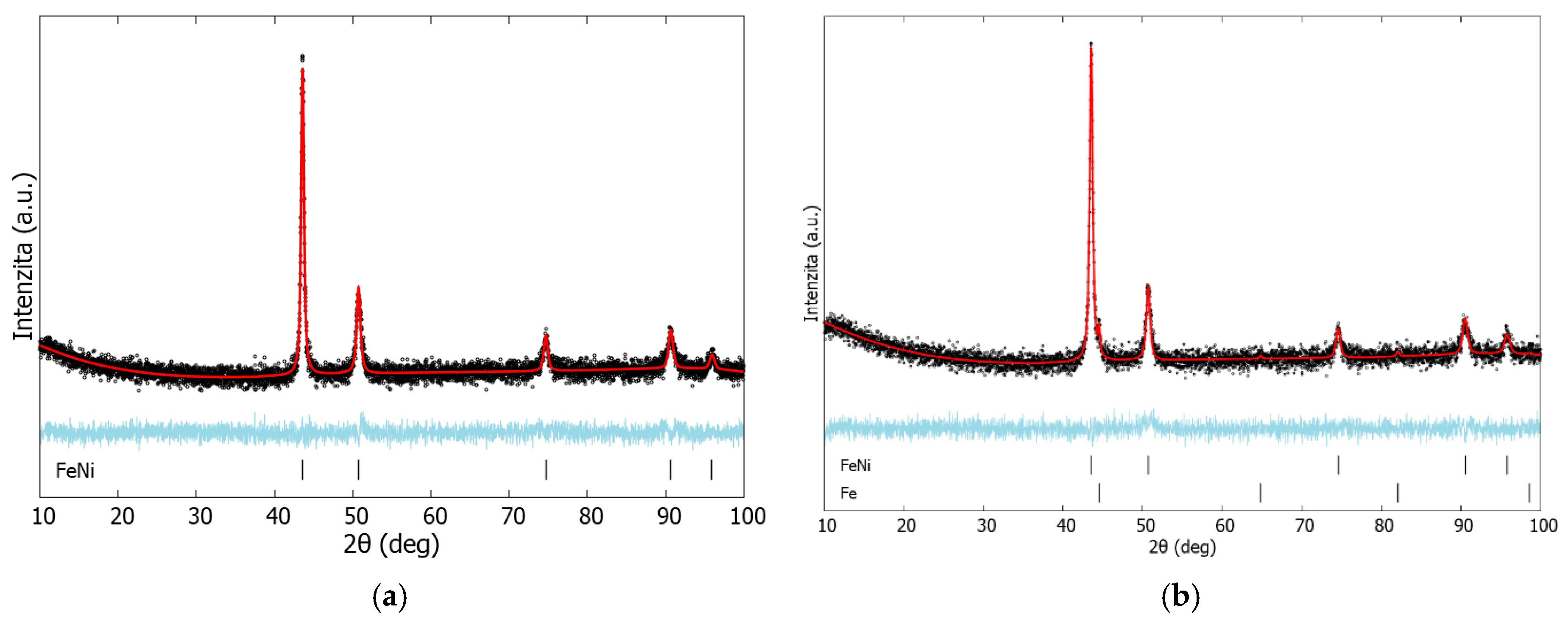
| Materials | aFeNi (Å) | aFe (Å) | FeNi (wt.%) | Fe (wt.%) | σ | Rwp (%) |
|---|---|---|---|---|---|---|
| E 18 8 Mn B 2 2 | 3.5961 | 2.8735 | 94.8 | 5.2 | 1.2 | 2.76 |
| E Ni 6625 | 3.5922 | - | 100 | - | 1.22 | 2.89 |
| Spectrum 1 | Spectrum 2 | Spectrum 3 | Spectrum 4 | |
|---|---|---|---|---|
| Elemt | Weight% | Weight% | Weight% | Weight% |
| Al | - | 53.12 | 53.02 | 46.94 |
| Si | 0.41 | 12.31 | 11.53 | 11.55 |
| Cr | 22.4 | 13.29 | 13.52 | 12.11 |
| Fe | 13.51 | 7.66 | 8.14 | 8.58 |
| Ni | 53.08 | 7.71 | 8.57 | 14.61 |
| Mo | 7.45 | 4.16 | 3.98 | 4.15 |
| Nb | 2.94 | 1.75 | 1.24 | 1.7 |
| Ti | 0.21 | - | - | 0.36 |
| Totals | 100.00 | 100.00 | 100.00 | 100.00 |
| Spectrum 1 | Spectrum 2 | Spectrum 3 | Spectrum 4 | |
|---|---|---|---|---|
| Element | Weight% | Weight% | Weight% | Weight% |
| Al | 79.46 | 57 | 55.17 | 49.42 |
| Si | 15.98 | 15.93 | 11.68 | 10.65 |
| Cr | 0.64 | 11.82 | 11.99 | 10.43 |
| Fe | 1.14 | 6.02 | 7.61 | 8.15 |
| Ni | 2.78 | 3.65 | 7.97 | 16.16 |
| Mo | - | 3.9 | 3.96 | 3.44 |
| Nb | - | 1.69 | 1.39 | 1.44 |
| Ti | - | - | 0.22 | - |
| Mn | - | - | - | 0.31 |
| Totals | 100.00 | 100.00 | 100.00 | 100.00 |
| Spectrum 1 | Spectrum 2 | Spectrum 3 | Spectrum 4 | |
|---|---|---|---|---|
| Elemt | Weight% | Weight% | Weight% | Weight% |
| Al | 88.92 | 58.57 | 58.66 | 57.50 |
| Si | 9.66 | 16.37 | 9.22 | 8.41 |
| Cr | - | 6.83 | 8.38 | 7.83 |
| Fe | 1.42 | 16.94 | 22.05 | 24.76 |
| Mn | - | 1.29 | 1.18 | 0.72 |
| Ni | - | - | 0.52 | 0.78 |
| Totals | 100.00 | 100.00 | 100.00 | 100.00 |
| Spectrum 1 | Spectrum 2 | Spectrum 3 | Spectrum 4 | |
|---|---|---|---|---|
| Elemt | Weight% | Weight% | Weight% | Weight% |
| Al | 85.70 | 63.22 | 58.05 | 50.19 |
| Si | 50.19 | 7.97 | 9.04 | 7.32 |
| Cr | - | 6.84 | 7.79 | 8.85 |
| Fe | 0.43 | 20.70 | 23.73 | 28.88 |
| Mn | - | 1.27 | 0.94 | - |
| Ni | 0.58 | - | 0.45 | 4.07 |
| Totals | 100.00 | 100.00 | 100.00 | 100.00 |
 | Spectrum 1 | Spectrum 2 | ||
| Element | Weight% | Element | Weight% | |
| O | 0.62 | Al | 58.91 | |
| Al | 82.6 | Si | 9.68 | |
| Si | 15.28 | Cr | 7.92 | |
| Fe | 0.58 | Mn | 1 | |
| Ni | 0.92 | Fe | 21.87 | |
| - | - | Ni | 0.62 | |
| Totals | 100.00 | Totals | 100 | |
 | Spectrum 1 | Spectrum 2 | ||
| Element | Weight% | Element | Weight% | |
| Al | 84.36 | Al | 59.16 | |
| Si | 15.09 | Si | 9.55 | |
| Ni | 0.55 | Cr | 7.94 | |
| Totals | 100 | Mn | 0.99 | |
| - | - | Fe | 22.36 | |
| - | - | Totals | 100 | |
| Immersion 120 Min | Immersion 300 Min | |||||
|---|---|---|---|---|---|---|
| Statistic Parameters | BM | E 18 8 Mn B 2 2 | E Ni 6625 | BM | E 18 8 Mn B 2 2 | E Ni 6625 |
| Average | 20 | 39 | 186 | 28 | 131 | 442 |
| StDev | 7.4 | 17.4 | 7.4 | 34 | 34 | 43 |
| Max | 35 | 80 | 200 | 160 | 160 | 500 |
| Min | 10 | 18 | 150 | 52 | 52 | 350 |
© 2019 by the authors. Licensee MDPI, Basel, Switzerland. This article is an open access article distributed under the terms and conditions of the Creative Commons Attribution (CC BY) license (http://creativecommons.org/licenses/by/4.0/).
Share and Cite
Brezinová, J.; Džupon, M.; Vojtko, M.; Viňáš, J.; Milkovič, O.; Brezina, J.; Guzanová, A.; Draganovská, D. Application of Cold Metal Transfer Welding for High Pressure Die Casting Mold Restoration. Metals 2019, 9, 1232. https://doi.org/10.3390/met9111232
Brezinová J, Džupon M, Vojtko M, Viňáš J, Milkovič O, Brezina J, Guzanová A, Draganovská D. Application of Cold Metal Transfer Welding for High Pressure Die Casting Mold Restoration. Metals. 2019; 9(11):1232. https://doi.org/10.3390/met9111232
Chicago/Turabian StyleBrezinová, Janette, Miroslav Džupon, Marek Vojtko, Ján Viňáš, Ondrej Milkovič, Jakub Brezina, Anna Guzanová, and Dagmar Draganovská. 2019. "Application of Cold Metal Transfer Welding for High Pressure Die Casting Mold Restoration" Metals 9, no. 11: 1232. https://doi.org/10.3390/met9111232
APA StyleBrezinová, J., Džupon, M., Vojtko, M., Viňáš, J., Milkovič, O., Brezina, J., Guzanová, A., & Draganovská, D. (2019). Application of Cold Metal Transfer Welding for High Pressure Die Casting Mold Restoration. Metals, 9(11), 1232. https://doi.org/10.3390/met9111232