Article

Microstructure and Mechanical Properties of Gas Tungsten Arc Welded High Manganese Steel Sheet

1
Advanced Surface Coating and Processing R&D Group, Korea Institute for Industrial Technology, Busan 46938, Korea
2
Department of Materials Science and Engineering, Pukyong National University, Busan 48513, Korea
3
School of Materials Science and Engineering, Pusan National University, Busan 46241, Korea
4
School of Materials Science and Engineering, Ulsan National University, Ulsan 44610, Korea
5
School of Materials Science and Engineering, Yeungnam University, Gyeongsan 38541, Korea
*
Authors to whom correspondence should be addressed.
Metals 2019, 9(11), 1167; https://doi.org/10.3390/met9111167
Submission received: 27 September 2019 / Revised: 21 October 2019 / Accepted: 24 October 2019 / Published: 29 October 2019

Abstract

:
This study investigated microstructure and mechanical properties of high manganese steel sheet fabricated by gas tungsten arc welding (GTAW). The weld zone showed longitudinal coarse grains due to the coalescence of columnar dendrites grown into the direction of heat source, and the HAZ showed equiaxed coarser grains than the base metal due to the thermal effect of GTAW process. Mn segregation occurred in the inter-dendritic regions of the weld zone and Mn depletion thus occurred in the weld matrix. Although the stacking fault energy is expected to be lowered due to the Mn depletion, no noticeable change in the initial phase and deformation mechanism was found in the weld matrix. Lower hardness and strength were shown in the weld zone than the base metal, which was caused by the coarser grain size. The negative strain rate sensitivity observed in the weld zone and the base metal is considered to have originated from the negative strain rate dependency of twinning nucleation stress.

1. Introduction

Due to global environmental issues, the demand for cryogenic industries relating to clean liquefied natural gas (LNG) has been increasing. Materials with excellent mechanical properties at cryogenic temperatures are thus required for stable transportation and storage of LNG. Traditionally, cryogenic steel pipes are made of 300-grade stainless steels such as STS304 and STS316 and 9%-Ni steel, but due to their high cost, industries are requiring new cryogenic steel grades. In this regard, high manganese steel has been recently attracting attention as a new cryogenic steel grade.
For decades, high manganese steel has been studied for the application of automotive frame due to its excellent strength–ductility combination from the early stage of development [1,2,3,4,5,6,7]. Recently high manganese steel was tried to be applied for slurry pipes due to its excellent wear resistance. In addition, as LNG ships and carriers have been in the spotlight recently, high manganese steel is receiving attention as a material for cryogenic steel pipes. From this point of view, studies on the processing technology such as forming, welding and heat treatment have been conducted in recent years [8,9,10,11,12].
One of the issues that must be resolved for high manganese steel to be used in LNG applications is weldability evaluation for pipe manufacturing. In this regard, several welding processes on high manganese steel have been investigated, such as RSW (Resistance Spot Welding), GTAW (Gas Tungsten Arc Welding), CLBW (Continuous Laser Beam Welding), PLBW (Pulsed Laser Beam Welding) and FCAW (Flux Cored Arc Welding) [12,13,14,15,16,17,18,19]. Common issues aroused are (1) manganese evaporation may occur during welding due to the high vapor pressure of manganese, (2) manganese segregation and deficiency may occur due to high manganese content. M3C carbides can be formed in the segregated region while the epsilon phase can be formed in the deficient region, which degrades the mechanical properties of weld zone. (3) Mechanical properties may show anisotropy owing to the difference in grain size in heat affected zone (HAZ) and weld zone, and (4) residual stresses may also lead to property degradation.
If the manganese content in the weld zone changes during welding due to the evaporation of manganese, initial phase and deformation mechanism may alter depending on stacking fault energy, which may cause inhomogeneous microstructure and local stress concentration during deformation [12,18,20]. Therefore, it is necessary to minimize the evaporation of manganese or to use filler metals of higher manganese content for compensating the evaporated amount [13,21]. Also, the M3C carbide in the weld zone may cause deterioration of the mechanical properties [16,22,23], so solid-solutionizing may be necessary before deformation processes such as forming, drawing and bending.
Even though a few studies have been reported on weld properties of high manganese steels, fundamental research on welding properties of high manganese steel is highly required due to the recently arising industrial demand for manufacturing high manganese steel pipes. In this study, GTAW—one of the industrially applicable welding techniques—was thus applied to a high manganese steel sheet. This work focused on the welding microstructure and mechanical properties of a 24Mn high manganese steel sheet jointed by GTAW. The microstructural changes before and after the GTAW were analyzed and the resultant effect on mechanical properties were discussed.

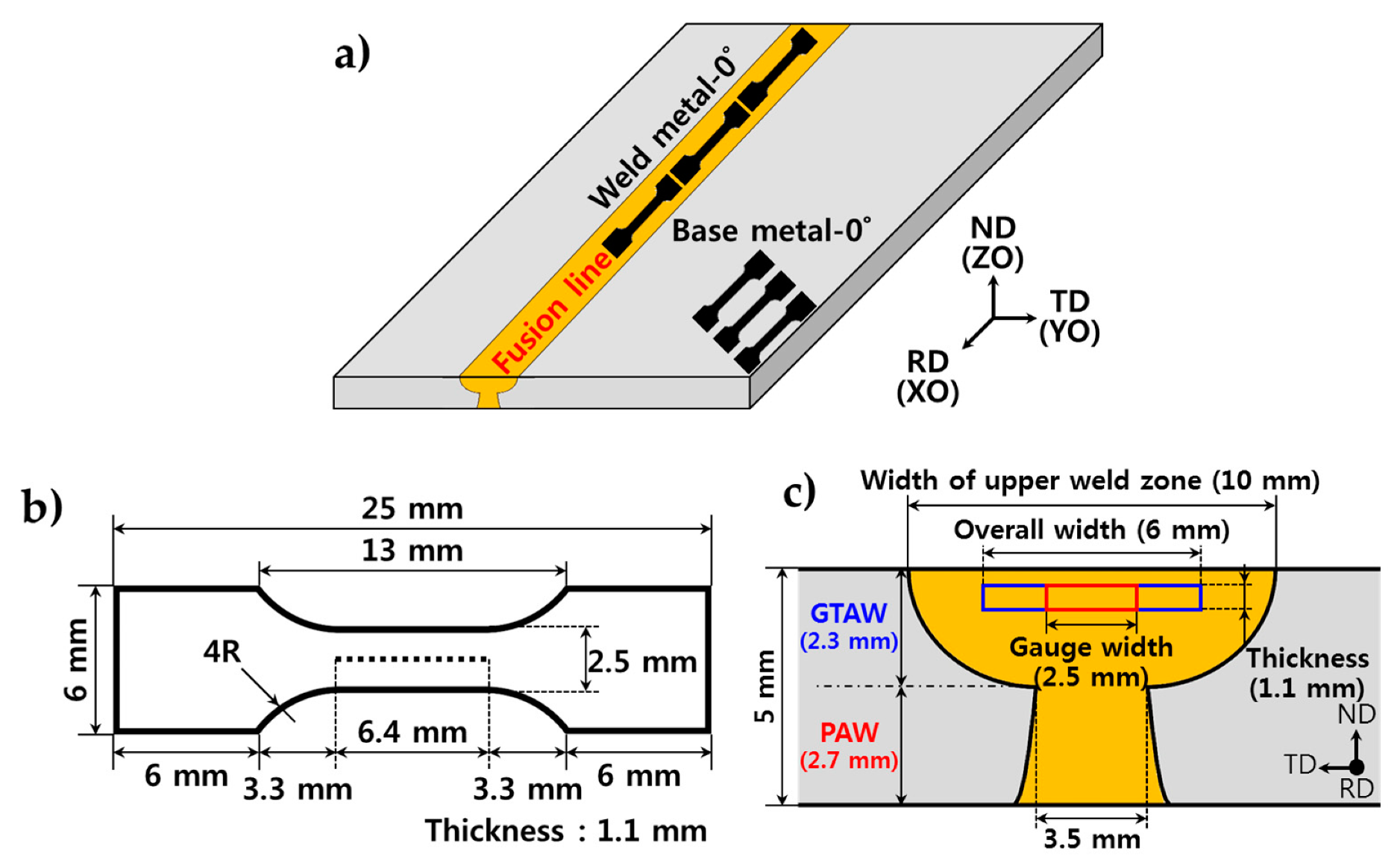
2. Materials and Methods

The chemical composition of the present high Mn steel is shown in Table 1. The 5 mm-thick hot- rolled steel sheet was welded without using a filler material, in such a way that the first single pass was primarily welded through a plasma arc welding (PAW), and then the second single pass was welded through the successive GTAW as shown in Figure 1. For commercial reasons, PAW was here employed for the first welding pass thanks to its fast welding speed and the remaining volume was welded by successive GTAW. The present work only deals with properties of the welded joint by GTAW and those by PAW will be published elsewhere. Automatic GTAW was conducted with a speed of 50 cm/min and with a condition of 18 V and 150 A. Heat input was 3.24 kJ/cm and shielding gas was nitrogen. Three identically-welded sheets of 50 cm long were used for evaluating microstructure and mechanical properties.
In order to observe the cross-sectional microstructures of the base, the HAZ and the weld zone, specimens were polished and color-etched for 30 s in a 10% nital (10% NHO3 + ethanol) and for 10 s in Klemm’s I (50 mL saturated aqueous Na2S2O3 + 1 g K2S2O5) [24,25].
In order to analyze stable phase, x-ray diffraction method was applied with Cu target source using Bruker X. To characterize stable phases, crystal orientations and twin boundaries, electron-backscattered diffraction (EBSD) method was also performed using JEOL-7200F (JEOL, Tokyo, Japan) and Oxford Nordlys Nano (Oxford Instruments, High Wycombe, UK). For composition analysis, energy dispersive X-ray spectroscopy (EDS) analysis was performed using JEOL-7200F and Oxford NanoAnalysis. Hardness test and tensile test were performed to evaluate the mechanical properties of the weld zone and the base metal. The hardness test was performed using a Vickers hardness tester (Mitutoyo HM-200, Tokyo, Japan) with the load of 4.903N and the dwell time of 10 s. Tensile test was carried out using a MTS tensile tester (Eden Praire, MN, USA), and the tensile specimen is a subsized type whose gauge length is 6.4 mm, specimen width is 2.5 mm and specimen thickness is 1.1 mm as shown in Figure 1b. Weldment specimens were sampled parallel to the welding direction, and the specimen gauge included only the GTAW weld zone as depicted in Figure 1c. The base specimen was taken parallel to the rolling direction, which coincided with the welding direction. Yield strength, tensile strength and elongation was measured according to ASTM A370. The strain rate of the tensile test was set to 10−3/s, the yield strength was determined by the 0.2% offset method, and the tensile strength was determined with the maximum load point. Elongation was measured by travel distance of crosshead.

3. Results and Discussion

Figure 2 shows the optical micrographs of the base metal, the HAZ and the weld zone. The base metal consists of equiaxed grains with a grain size of 15 μm and hot-rolling strips elongated in the rolling direction (Figure 2b). The hot-rolling strips were confirmed as segregation bands of Mn and C by EDS analysis (Figure 3a). In the coarse-grained heat affected zone (CG-HAZ), grain growth occurred by the high thermal input of GTAW to have a grain size of 30–60 μm. The weld zone has interdendritic regions indicating that welding solidification occurred in the manner of columnar dendritic structure. The columnar dendrites are known to grow parallel to the maximum heat flow direction and were observed to be aligned towards the welding heat source (Figure 2e).
From the EDS results in Figure 3, it can be seen that Mn was micro-segregated into the interdendritic region during solidification. The solute atoms released upon solidification were concentrated in the interdendritic region as the solid–liquid interface advanced and the interdendritic region was solidified at the lowest temperature. During solidification, in other words, it is deduced that Mn was rejected by the melt, and the fast enough cooling rate by GTAW limited diffusion rate in the solid, which finally resulted in the interdendritic region with high Mn concentration. Mn segregation is not desirable because it induces inhomogeneity of the weld microstructure and may degrade the mechanical properties of the weld. Also, it may cause the formation of brittle phases such as MnS and MnC, which is not preferable [26,27]. At the same time, Mn segregation may alter deformation mechanism of the matrix in the weld zone due to the Mn depletion [28,29].
For this reason, Mn contents of the matrix and the interdendritic regions were quantitatively analyzed in Figure 3b. In the base metal, Mn segregation occurred into the hot-rolling strips with 26.7 wt.% of Mn, while the matrix had 21.6 wt.% of Mn. In the hot-rolling strips, carbon was also segregated while other elements such as P and S could be not identified. In the HAZ, it was confirmed that the Mn diffusion occurred due to the thermal activation by welding heat input, so that the segregation tendency of Mn and C was weaker than that of the base metal. In the weld zone, Mn and C were concentrated in the interdendritic regions by rejection of the solute atoms from the liquid during solidification. A high Mn concentration of 26.8 wt.% was observed in the interdendritic region, while a low Mn concentration of 20.9 wt.% was shown in the matrix. From the quantitative analysis of Mn in the weld zone, it can be seen that the possible Mn evaporation due to the high vapor pressure of Mn during welding, which was previously reported in laser welding studies [12,13,30,31], did not occur significantly in the present GTAW process.
The deformation mechanism of high manganese steel depends on stacking fault energy (SFE) of austenite [32,33,34]. As the SFE increases, the deformation mechanism changes from epsilon martensite to deformation twinning and further to planar dislocation glide. SFE is highly dependent on alloy compositions. In case of the present 0.4C-24Mn-4Cr steel, the deformation of austenite is known to be mainly accompanied by deformation twinning [35]. Due to the manganese depletion in the matrix of the base metal and the weldment as shown in Figure 3, the SFE can be possibly changed and may alter the deformation mechanism.
According to Sato et al. [36], epsilon martensite formation during deformation was hindered and deformation was mainly accommodated by deformation twinning above which SFE is over 20 mJ/m2. Remy et al. [34] reported that deformation twinning occurred when the SFE of the Fe-(20–32)wt.%Cr-C alloy is 10 to 40 mJ/m2 and below that, epsilon martensite was formed. Since SFE is known to depend on chemical composition, it is necessary to identify SFE by considering the chemical composition of the present alloy system. In particular, Mn is an alloying element that increases SFE, and depletion of Mn in the dendiritic matrix may affect the initial phase and deformation mechanism in the present weld zone.
In this study, the SFE was calculated based on the Mn composition measured by EDS to predict the possible change in deformation mechanism due to micro-segregation of Mn. Among several references, the formulas presented by Dumay et al. [37] and Crutze et al. [38] were employed as shown in Figure 4. These formulas have been applied in several articles [39,40,41] and are known to quantitatively predict experimental SFE well. Based on Dumay’s equation, assuming that no Mn segregation occurs, SFE of 18.5 mJ/m2 for the present nominal composition was obtained. If Mn segregation occurs, the matrix of the base and the weld showed about 13 mJ/m2 showing that the SFE decreased with decreasing Mn content. On the contrary, in the interdendritic regions and the hot-rolling strips where Mn segregation occurred, the SFE increased to about 22 mJ/m2. Curtze’s equation predicted higher SFEs than Dumay’s equation, but the tendency of SFE change due to Mn segregation was similar. From this calculation, it can be inferred that the SFEs of the base and the weld were changed due to the Mn segregation. In particular, it should be noted that the matrix of the base and the weld in which the manganese depletion has occurred showed lower SFEs, so that epsilon martensite transformation may partially occur during deformation.
In order to verify the existence of epsilon martensite, XRD analysis was performed as shown in Figure 5. It was observed that initial microstructure was composed of full austenite in both the base and the weld metal. To confirm the deformation-induced phase transformation, each specimen was uni-axially deformed at a strain rate of 10−3/s and the fractured specimens were examined by XRD, showing that epsilon martensite was not formed until fracture. Additionally, it was confirmed that epsilon martensite was not generated during deformation even though the strain rate was changed as 100 times higher to 10−1/s. From this observation, it can be inferred that although the manganese depletion in the matrix did occur during welding making SFE of the matrix decreased, the depletion was not enough to induce the epsilon martensite during deformation. In other words, the segregation and the depletion of Mn during the present GTAW did not change the initial and the deformed phase of the present high Mn steel.
Figure 6 shows a phase map and inverse pole figure (IPF) maps of the base, the HAZ and the weld metal analyzed by EBSD. Austenitic single phase was identified in the whole region as confirmed previously by XRD in Figure 5a. From the EDS analysis and the SFE calculations above, it was observed that Mn depletion occurred on the weld matrix, but the initial stable phase was retained as austenite. IPF maps show that dendrites were grown into the <100> direction toward the heat source during solidification. It can be inferred that single dendritic phases with similar crystal orientations were integrated into the one type of coarse grain and have become the longitudinal grains with about 100 μm wide and about 500 μm long having an aspect ratio of 1:5. Degradation in the strength is expected due to the coarse grains in the weld zone. Also, mechanical properties are expected to be anisotropic due to the directional solidification structure of the grains in the weld zone. In the HAZ, grain growth occurred due to high heat input during welding clearly showing CG-HAZ as already depicted in Figure 2c. The CG-HAZ retained the random texture from the base metal and is expected to lose strength due to the coarser grains. The base material showed equiaxed grains with random texture.
Figure 7 shows hardness profiles including the base the HAZ and the weld zone. The base exhibited a hardness of about 220–240 HV and the HAZ showed a clear decrease in hardness to about 200 HV owing to the coarser grains regardless of the sample thickness. The weld zone showed the lowest hardness of about 180 HV due to coarser grains formed by coalescence of columnar dendrite during solidification. The difference of the hardness between the base and the weld were clearly shown and thus it is expected that the weld zone will be primarily deformed upon plastic deformation where the base and the weld zone are co-existing as deformation along the transverse direction.
Figure 8 shows engineering stress–strain curves of uniaxial tensile test on the base and the weld zone. To determine the strain rate sensitivity, two different strain rates of 10−3/s and 10−1/s were performed respectively. At both strain rates, the yield stresses of the weld metal were lower than those of the base metal. This is due to the coarser grains of the weld than the base metal. Possibly due to the difference in work hardening tendency mainly influenced by the grain size, the weld zone also showed lower tensile stresses than the base. By observing fracture surfaces, it was found that ductile fracture occurred in the base and the weld metal regardless of the strain rate. Larger dimples were observed in the weld zone than the base understandably due to the coarser grains formed in the weld zone (Figure 9).
Figure 10 shows the true strain–stress curves and strain rate sensitivity of the base metal and the weld at the two strain rates. Strain rate sensitivity (SRS) was calculated by the following equation [42].
m = m i + m t = log ( σ i / σ 1 ) log ( ε ˙ 2 / ε ˙ 1 ) | ε + log ( σ 2 / σ i ) log ( ε ˙ 2 / ε ˙ 1 ) | ε = log ( σ 2 / σ 1 ) log ( ε ˙ 2 / ε ˙ 1 )
In general metals, it is known that the faster the strain rate, the higher the flow stress, showing positive SRS [43,44]. In the base metal of the present high Mn steel, however, the flow stress was lower at 10−1/s than at 10−3/s after 40% of true strain. In other words, the base metal showed negative strain rate sensitivity at 100 times faster strain rate of 10−1/s after 40% of true strain. In the weld zone, on the other hand, the negative strain rate sensitivity was shown right after the yield point, becoming more negative under continuous deformation. To our knowledge, this study is the first report on the strain rate sensitivity shown in the weldment of high Mn steel.
This negative strain rate sensitivity has been reported in high manganese steels [42,45,46] and magnesium alloys [47], where mechanical twinning has a significant effect on the deformation behavior. The possible mechanism for negative SRS is proposed as follows: first, negative strain rate dependence of twin nucleation stress; second, negative strain rate dependence of twin growth rate; and third, dynamic strain aging (DSA) by solid solution [48,49]. The EBSD images in Figure 11 show the deformation twin formation in the base and the weld zone at e = 0.1 (ε = 0.095) and e = 0.5 (ε = 0.405) depending on the strain rate. In the weld zone, more deformation twins were observed when strain rate was 100 times faster when e = 0.1 (ε = 0.095), and where SRS, m, is larger than 0. However, when an additional strain was applied till engineering strain reached 0.5 (ε = 0.405), EBSD images clearly showed that the nucleation of the twin was slowed when strain was 100 times faster from 10−3/s to 10−1/s as shown in Figure 11b. In the base material, on the other hand, the twin boundary density tended to increase with increasing strain rate at e = 0.1 (ε = 0.095) where m > 0. Contrary to the weld zone, twin boundary density was still higher at the higher strain rate, 10−1/s, even when e = 0.5 (ε = 0.405), and where SRS, m, still showed positive value. From this result, the negative SRS shown in the plasticity of the present weld zone can be explained in a way that deformation twin nucleation occurred slower as the strain rate increased, thereby reducing the dynamic hall-petch effect of the twin boundaries and diminishing the strain hardening effect.

4. Conclusions

Microstructure and mechanical properties of a gas-tungsten-arc-welded high manganese steel sheet were investigated. The results are summarized as follows:
(1)
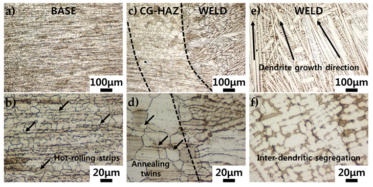
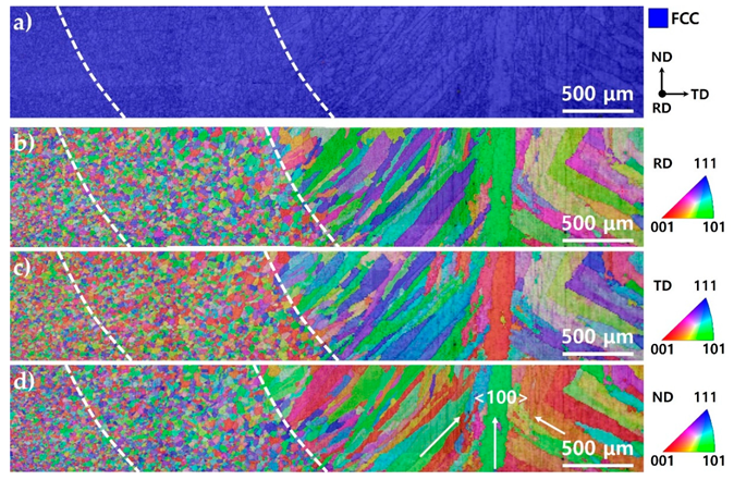
The weld zone was composed of coarse grains by coalescence of columnar dendrite, and HAZ showed equiaxed coarser grains than the base metal due to the thermal effect of the current GTAW process. Austenite single phase was found in all the regions including the weld zone, HAZ and base metal.
(2)
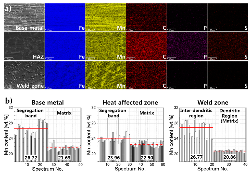
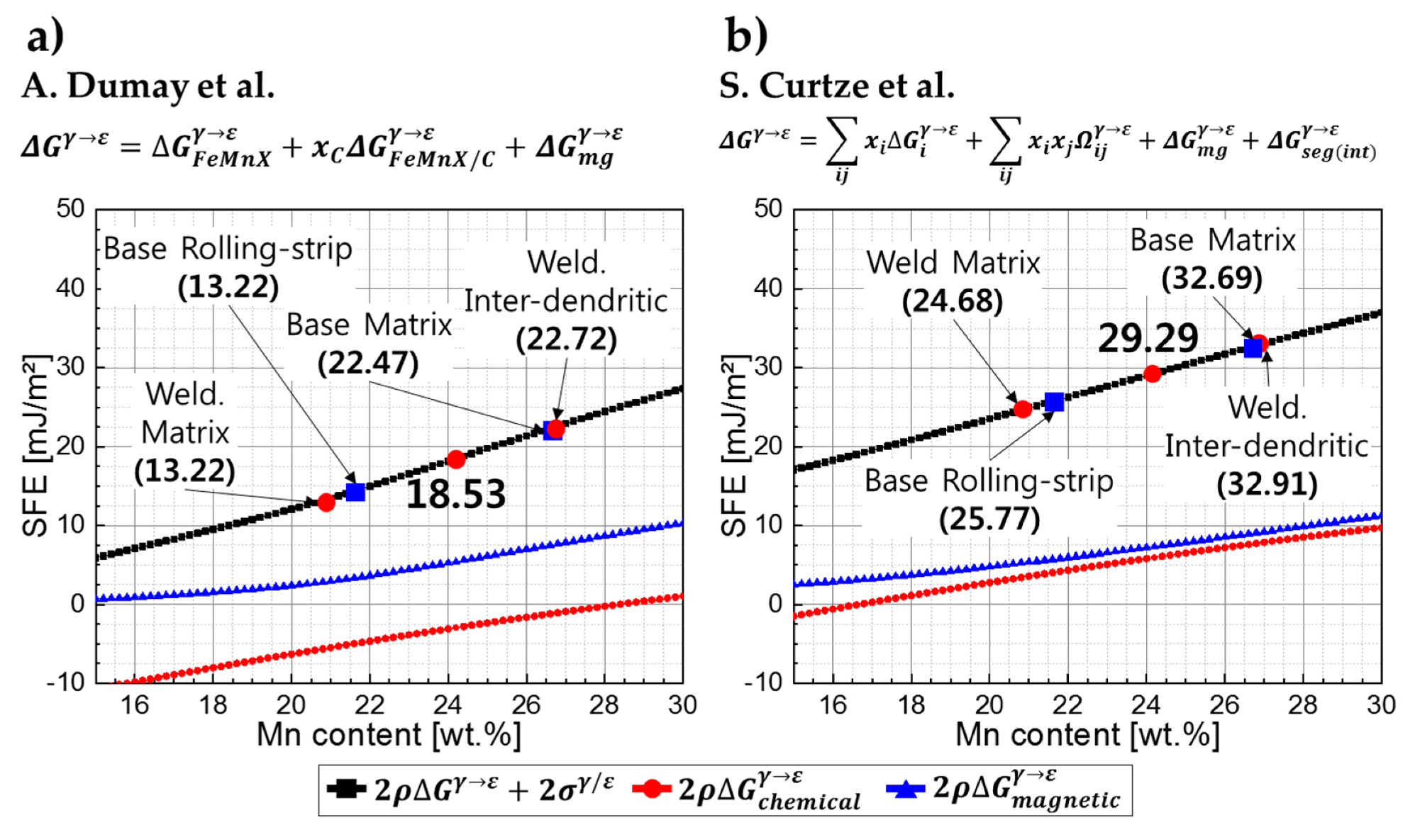
Mn segregation occurred in the interdendritic regions of the weld zone, resulting in Mn depletion of the weld matrix. SFE of the weld matrix was predicted to be lower than the nominal composition, but no significant changes in initial phase or deformation mechanism was observed. Mn evaporation during the present GTAW process also seems to have little effect on the initial phase and the deformation mechanisms.
(3)
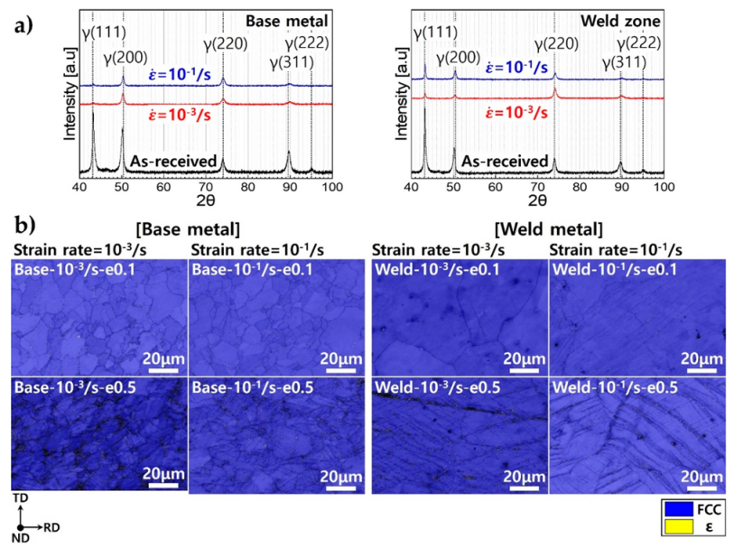
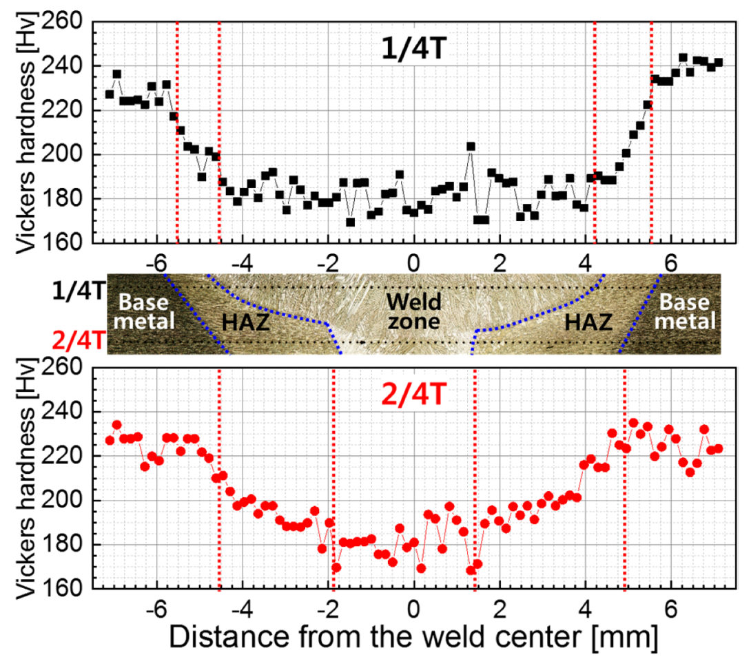
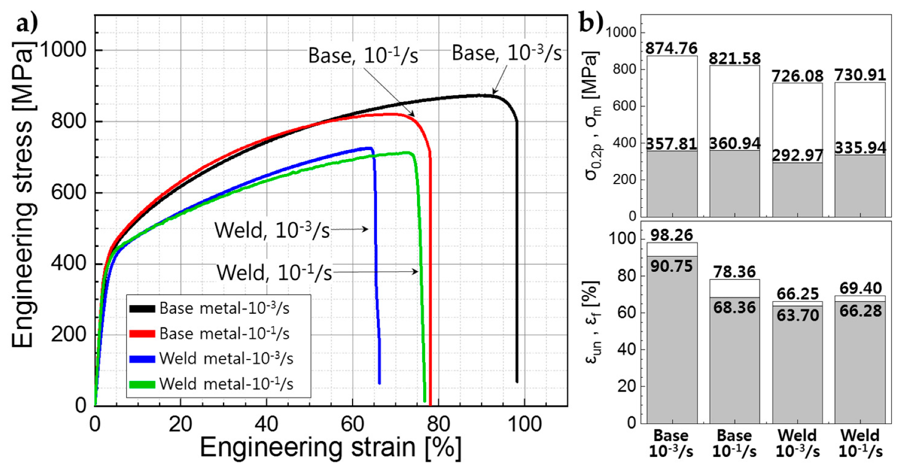
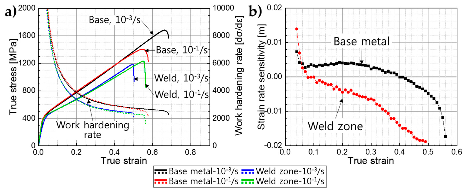
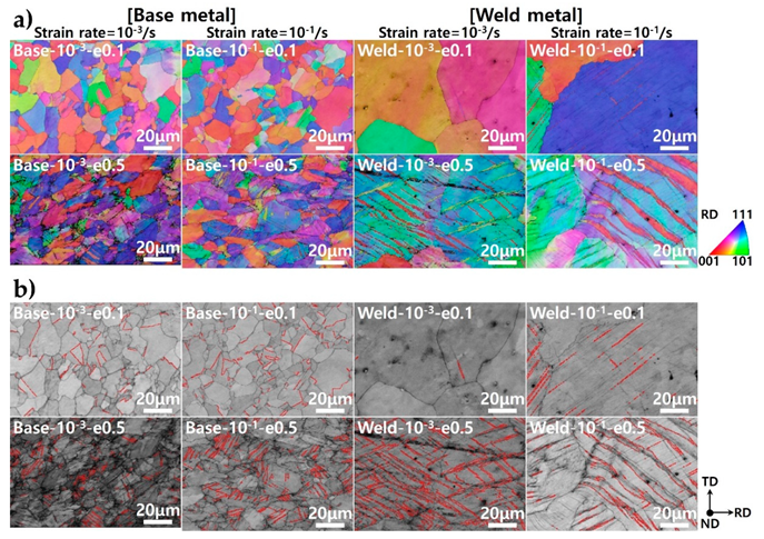
The weld zone showed lower hardness and strength than the base and the HAZ due to its coarse grains. The HAZ showed lower hardness compared to the base metal due to the grain growth by thermal effect during GTAW. The negative strain rate sensitivity shown in the weld zone and the base metal is believed to have originated from the negative strain rate dependency of twin nucleation stress which resulted in the lesser formation of deformation twin boundaries during deformation.

Author Contributions

G.-W.P. and J.B.J. conceived and designed the experiments; G.-W.P. and H.J. analyzed microstructure of base metal and measure mechanical properties; G.-W.P. and M.P. analyzed microstructure of the welds and measured mechanical properties; G.-W.P., W.-S.K. and J.B.J. performed the thermodynamic calculations; S.S. analyzed EBSD data; B.-J.K. and N.P. discussed the data regarding negative strain rate sensitivity; G.-W.P., Y.-S.A. and J.B.J. wrote the paper.

Acknowledgments

This study was supported by the R&D Program of the “World Class 300 Project (R&D) (S2641289, Development of high value-added forged flanges for extreme environments based on intelligent forging systems) of the SMBA (Korea)” and also partly supported by the R&D Program of the Korea Evaluation Institute of Industrial Technology (KEIT) as “Development of Sub-merged-Arc-Welded Pipe and Extruded Pipe made of High Manganese Steel for Cryogenic Usage in LNG Ship and Offshore Plant (10080728)”.

Conflicts of Interest

The authors declare no conflict of interest.

References

  1. De Cooman, B.C.; Kwon, O.; Chin, K.G. State-of-the-knowledge on TWIP steel. Mater. Sci. Technol. 2012, 28, 513–527. [Google Scholar] [CrossRef]
  2. Gutierrez-Urrutia, I.; Zaefferer, S.; Raabe, D. The effect of grain size and grain orientation on deformation twinning in a Fe–22wt.% Mn–0.6wt.% C TWIP steel. Mater. Sci. Eng. A 2010, 527, 3552–3560. [Google Scholar] [CrossRef]
  3. De Cooman, B.C.; Estrin, Y.; Kim, S.K. Twinning-induced plasticity (TWIP) steels. Acta Mater. 2018, 142, 283–362. [Google Scholar] [CrossRef]
  4. Gutierrez-Urrutia, I.; Raabe, D. Grain size effect on strain hardening in twinning-induced plasticity steels. Scr. Mater. 2012, 66, 992–996. [Google Scholar] [CrossRef]
  5. De Cooman, B.C. 10-Phase transformations in high manganese twinning-induced plasticity (TWIP) steels. In Phase Transformations in Steels; Pereloma, E., Edmonds, D.V., Eds.; Woodhead Publishing: Cambridge, UK, 2012; pp. 295–331. ISBN 978-1-84569-971-0. [Google Scholar] [CrossRef]
  6. Tang, Z.; Huang, J.; Ding, H.; Cai, Z.; Zhang, D.; Misra, D. Effect of Deformation Temperature on Mechanical Properties and Deformation Mechanisms of Cold-Rolled Low C High Mn TRIP/TWIP Steel. Metals 2018, 8, 476. [Google Scholar] [CrossRef]
  7. Madivala, M.; Schwedt, A.; Prahl, U.; Bleck, W. Strain Hardening, Damage and Fracture Behavior of Al-Added High Mn TWIP Steels. Metals 2019, 9, 367. [Google Scholar] [CrossRef]
  8. Grajcar, A.; Borek, W. Thermo-mechanical processing of high-manganese austenitic TWIP-type steels. Arch. Civ. Mech. Eng. 2008, 8, 29–38. [Google Scholar] [CrossRef]
  9. Mi, Z.-L.; Tang, D.; Jiang, H.-T.; Dai, Y.-J.; Li, S.-S. Effects of annealing temperature on the microstructure and properties of the 25Mn-3Si-3Al TWIP steel. Int. J. Miner. Metall. Mater. 2009, 16, 154–158. [Google Scholar] [CrossRef]
  10. Vercammen, S.; Blanpain, B.; De Cooman, B.C.; Wollants, P. Cold rolling behaviour of an austenitic Fe–30Mn–3Al–3Si TWIP-steel: The importance of deformation twinning. Acta Mater. 2004, 52, 2005–2012. [Google Scholar] [CrossRef]
  11. Razmpoosh, M.H.; Zarei-Hanzaki, A.; Heshmati-Manesh, S.; Fatemi-Varzaneh, S.M.; Marandi, A. The Grain Structure and Phase Transformations of TWIP Steel During Friction Stir Processing. J. Mater. Eng. Perform. 2015, 24, 2826–2835. [Google Scholar] [CrossRef]
  12. Mújica Roncery, L.; Weber, S.; Theisen, W. Welding of twinning-induced plasticity steels. Scr. Mater. 2012, 66, 997–1001. [Google Scholar] [CrossRef]
  13. Ma, L.-L.; Wei, Y.-H.; Hou, L.-F.; Yan, B. Microstructure and Mechanical Properties of TWIP Steel Joints. J. Iron. Steel Res. Int. 2014, 21, 749–756. [Google Scholar] [CrossRef]
  14. Saha, D.C.; Cho, Y.; Park, Y.D. Metallographic and fracture characteristics of resistance spot welded TWIP steels. Sci. Technol. Weld. Join. 2013, 18, 711–720. [Google Scholar] [CrossRef]
  15. Han, I.-W.; Eom, J.-B.; Yun, J.-G.; Lee, B.-G.; Kang, C.-Y. Microstructure and Hardness of 1st layer with Crystallographic Orientation of Solidification Structure in Multipass Weld using High Mn-Ni Flux Cored Wire. J. Weld. Join. 2016, 34, 77–82. [Google Scholar] [CrossRef]
  16. Park, G.; Kim, B.; Kang, Y.; Kang, H.; Lee, C. Characterization of bond line discontinuities in a high-Mn TWIP steel pipe welded by HF-ERW. Mater. Charact. 2016, 118, 14–21. [Google Scholar] [CrossRef]
  17. Ahmed, M.M.Z.; Ahmed, E.; Hamada, A.S.; Khodir, S.A.; El-Sayed Seleman, M.M.; Wynne, B.P. Microstructure and mechanical properties evolution of friction stir spot welded high-Mn twinning-induced plasticity steel. Mater. Des. 2016, 91, 378–387. [Google Scholar] [CrossRef]
  18. Keil, D.; Zinke, M.; Pries, H. Investigations on Hot Cracking of Novel High Manganese TWIP-Steels. In Hot Cracking Phenomena in Welds III; Böllinghaus, T., Lippold, J., Cross, C.E., Eds.; Springer Publishing: Berlin/Heidelberg, Germany, 2011; pp. 209–223. ISBN 978-3-642-16864-2. [Google Scholar] [CrossRef]
  19. Kazdal Zeytin, H.; Ertek Emre, H.; Kaçar, R. Properties of Resistance Spot-Welded TWIP Steels. Metals 2017, 7, 14. [Google Scholar] [CrossRef]
  20. Frommeyer, G.; Brüx, U.; Neumann, P. Supra-Ductile and High-Strength Manganese-TRIP/TWIP Steels for High Energy Absorption Purposes. ISIJ Int. 2003, 43, 438–446. [Google Scholar] [CrossRef]
  21. Májlinger, K.; Kalácska, E.; Russo Spena, P. Gas metal arc welding of dissimilar AHSS sheets. Mater. Des. 2016, 109, 615–621. [Google Scholar] [CrossRef]
  22. Yoo, J.; Han, K.; Park, Y.; Choi, J.; Lee, C. Evaluation of solidification cracking susceptibility of Fe–18Mn–0·6C steel welds. Sci. Tehcnol. Weld. Join. 2014, 19, 514–520. [Google Scholar] [CrossRef]
  23. Saha, D.C.; Chang, I.; Park, Y.-D. Heat-affected zone liquation crack on resistance spot welded TWIP steels. Mater. Charact. 2014, 93, 40–51. [Google Scholar] [CrossRef]
  24. Kusakin, P.; Belyakov, A.; Haase, C.; Kaibyshev, R.; Molodov, D.A. Microstructure evolution and strengthening mechanisms of Fe–23Mn–0.3C–1.5Al TWIP steel during cold rolling. Mater. Sci. Eng. A 2014, 617, 52–60. [Google Scholar] [CrossRef]
  25. Pérez Escobar, D.; Silva Ferreira de Dafé, S.; Brandão Santos, D. Martensite reversion and texture formation in 17Mn-0.06C TRIP/TWIP steel after hot cold rolling and annealing. J. Mater. Res. Technol. 2015, 4, 162–170. [Google Scholar] [CrossRef]
  26. Kim, D.; Han, K.; Lee, B.; Han, I.; Park, J.H.; Lee, C. Oxide Formation Mechanisms in High Manganese Steel Welds. Metall. Mater. Trans. A 2014, 45, 2046–2054. [Google Scholar] [CrossRef]
  27. Wang, T.; Zhang, M.; Xiong, W.; Liu, R.; Shi, W.; Li, L. Microstructure and tensile properties of the laser welded TWIP steel and the deformation behavior of the fusion zone. Mater. Des. 2015, 83, 103–111. [Google Scholar] [CrossRef]
  28. Mujica, L.; Weber, S.; Pinto, H.; Thomy, C.; Vollertsen, F. Microstructure and mechanical properties of laser-welded joints of TWIP and TRIP steels. Mater. Sci. Eng. A 2010, 527, 2071–2078. [Google Scholar] [CrossRef]
  29. Gong, Y.F.; Kim, H.S.; Kim, S.K.; De Cooman, B.C. Selective Oxidation and Sub-Surface Phase Transformation during Austenitic Annealing of TWIP Steels. Mater. Sci. Forum 2010, 654–656, 258–261. [Google Scholar] [CrossRef]
  30. Spencer, P.J.; Pratt, J.N. A study of the vapour pressure of manganese using a new high-temperature torsion—Effusion apparatus. Br. J. Appl. Phys. 1967, 18, 1473–1478. [Google Scholar] [CrossRef]
  31. Mujica, L.; Weber, S.; Thomy, C.; Vollertsen, F. Microstructure and mechanical properties of laser welded austenitic high manganese steels. Sci. Technol. Weld. Join. 2009, 14, 517–522. [Google Scholar] [CrossRef]
  32. Kim, J.-K.; De Cooman, B.C. Stacking fault energy and deformation mechanisms in Fe-xMn-0.6C-yAl TWIP steel. Mater. Sci. Eng. A 2016, 676, 216–231. [Google Scholar] [CrossRef]
  33. Schramm, R.E.; Reed, R.P. Stacking fault energies of seven commercial austenitic stainless steels. Metall. Trans. A 1975, 6, 1345. [Google Scholar] [CrossRef]
  34. Remy, L.; Pineau, A. Twinning and strain-induced F.C.C. → H.C.P. transformation in the Fe-Mn-Cr-C system. Mater. Sci. Eng. 1977, 28, 99–107. [Google Scholar] [CrossRef]
  35. Lee, S.-I.; Lee, S.-Y.; Han, J.; Hwang, B. Deformation behavior and tensile properties of an austenitic Fe-24Mn-4Cr-0.5C high-manganese steel: Effect of grain size. Mater. Sci. Eng. A 2019, 742, 334–343. [Google Scholar] [CrossRef]
  36. Sato, K.; Ichinose, M.; Hirotsu, Y.; Inoue, Y. Effects of Deformation Induced Phase Transformation and the Mechanical Properties of Austenitic Fe-Mn-AI Alloys. ISIJ Int. 1989, 29, 868–877. [Google Scholar] [CrossRef]
  37. Dumay, A.; Chateau, J.P.; Allain, S.; Migot, S.; Bouaziz, O. Influence of addition elements on the stacking-fault energy and mechanical properties of an austenitic Fe–Mn–C steel. Mater. Sci. Eng. A 2008, 483–484, 184–187. [Google Scholar] [CrossRef]
  38. Curtze, S.; Kuokkala, V.T.; Oikari, A.; Talonen, J.; Hänninen, H. Thermodynamic modeling of the stacking fault energy of austenitic steels. Acta Mater. 2011, 59, 1068–1076. [Google Scholar] [CrossRef]
  39. Bouaziz, O.; Allain, S.; Scott, C.P.; Cugy, P.; Barbier, D. High manganese austenitic twinning induced plasticity steels: A review of the microstructure properties relationships. Curr. Opin. Solid State Mater. Sci. 2011, 15, 141–168. [Google Scholar] [CrossRef]
  40. Saeed-Akbari, A.; Imlau, J.; Prahl, U.; Bleck, W. Derivation and Variation in Composition-Dependent Stacking Fault Energy Maps Based on Subregular Solution Model in High-Manganese Steels. Metall. Mater. Trans. A 2009, 40, 3076–3090. [Google Scholar] [CrossRef]
  41. Wu, Z.; Bei, H.; Pharr, G.M.; George, E.P. Temperature dependence of the mechanical properties of equiatomic solid solution alloys with face-centered cubic crystal structures. Acta Mater. 2014, 81, 428–441. [Google Scholar] [CrossRef]
  42. Bintu, A.; Vincze, G.; Picu, C.R.; Lopes, A.B.; Grácio, J.J.; Barlat, F. Strain hardening rate sensitivity and strain rate sensitivity in TWIP steels. Mater. Sci. Eng. A 2015, 629, 54–59. [Google Scholar] [CrossRef]
  43. Khan, A.S.; Liu, H. Variable strain rate sensitivity in an aluminum alloy: Response and constitutive modeling. Int. J. Plast. 2012, 36, 1–14. [Google Scholar] [CrossRef]
  44. Klepaczko, J.R.; Chiem, C.Y. On rate sensitivity of f.c.c. metals, instantaneous rate sensitivity and rate sensitivity of strain hardening. J. Mech. Phys. Solids 1986, 34, 29–54. [Google Scholar] [CrossRef]
  45. Zavattieri, P.D.; Savic, V.; Hector, L.G.; Fekete, J.R.; Tong, W.; Xuan, Y. Spatio-temporal characteristics of the Portevin–Le Châtelier effect in austenitic steel with twinning induced plasticity. Int. J. Plast. 2009, 25, 2298–2330. [Google Scholar] [CrossRef]
  46. Chen, L.; Kim, H.-S.; Kim, S.-K.; De Cooman, B.C. Localized Deformation due to Portevin–LeChatelier Effect in 18Mn–0.6C TWIP Austenitic Steel. ISIJ Int. 2007, 47, 1804–1812. [Google Scholar] [CrossRef]
  47. Chun, Y.B.; Davies, C.H.J. Twinning-induced negative strain rate sensitivity in wrought Mg alloy AZ31. Mater. Sci. Eng. A 2011, 528, 5713–5722. [Google Scholar] [CrossRef]
  48. Bolling, G.F.; Richman, R.H. Continual mechanical twinning: Part I: Formal description. Acta Metall. 1965, 13, 709–722. [Google Scholar] [CrossRef]
  49. Kubin, L.P.; Estrin, Y. Dynamic strain ageing and the mechanical response of alloys. J. Phys. III France 1991, 1, 929–943. [Google Scholar] [CrossRef]
Figure 1. Schematic diagrams showing (a) location and direction of tensile specimens, (b) dimension of the present subsized tensile specimen, (c) sampling location of tensile specimen.
Metals 09 01167 g001
Figure 2. Optical micrographs of the as-welded specimen etched by 10% nital for 30 s and Klemm’s I for 10 s: (a,b) base metal, (c,d) heat affected zone and (e,f) weld zone.
Metals 09 01167 g002
Figure 3. EDS analysis of base metal, heat affected zone (HAZ), and weld zone. (a) Image map analysis of base metal, heat affected zone, and weld metal. (b) Quantitative analysis for Mn in each region.
Metals 09 01167 g003
Figure 4. Stacking fault energy calculation depending on alloys content. Equations were presented by (a) Dumay et al. [37] and (b) Curtze et al. [38].
Metals 09 01167 g004
Figure 5. Phase analysis of tensile specimens after deformation. (a) X-ray diffraction pattern of tensile specimens deformed until fracture. (b) Electron-backscattered diffraction (EBSD) analysis results of phase map depending on the strain rate and deformation rate.
Metals 09 01167 g005
Figure 6. EBSD analysis results of the as-welded steel: (a) phase map, (bd) inverse pole figure (IPF) maps at rolling direction, transverse direction, and normal direction, respectively.
Metals 09 01167 g006
Figure 7. Vickers hardness profiles of the present high Mn steel ranging over welded joints regions.
Metals 09 01167 g007
Figure 8. The results of uniaxial tensile test on the base and the weld zone. All specimens were deformed along the welding (rolling) direction: (a) engineering stress–strain curves (strain rate of 10−3/s and 10−1/s). (b) Diagrams showing summarized mechanical properties of tensile test specimens.
Metals 09 01167 g008
Figure 9. SEM images of fractographs depending on the strain rate: (a,b) the base metal and the weld metal with strain rate of 10−3/s, (c,d) the base and the weld metal with strain rate of 10−1/s.
Metals 09 01167 g009
Figure 10. (a) True strain–stress curves and (b) strain rate sensitivity parameters calculated from the true strain–stress curves (strain rate of 10−3/s to 10−1/s).
Metals 09 01167 g010
Figure 11. Tensile direction inverse pole figure (TD-IPF) EBSD maps of base metal and weld zone. (a) IPF maps. (b) Twin boundary maps.
Metals 09 01167 g011
Table 1. Chemical composition of the present high manganese steel sheet.
wt.%CMnSiPSCrCuFe
ASTMA
240XM-M
0.4424.20.30.0010.0013.40.4Bal.

