Dissimilar Welding and Joining of Cemented Carbides

 and
and
Abstract
1. Introduction
2. Weld Processes
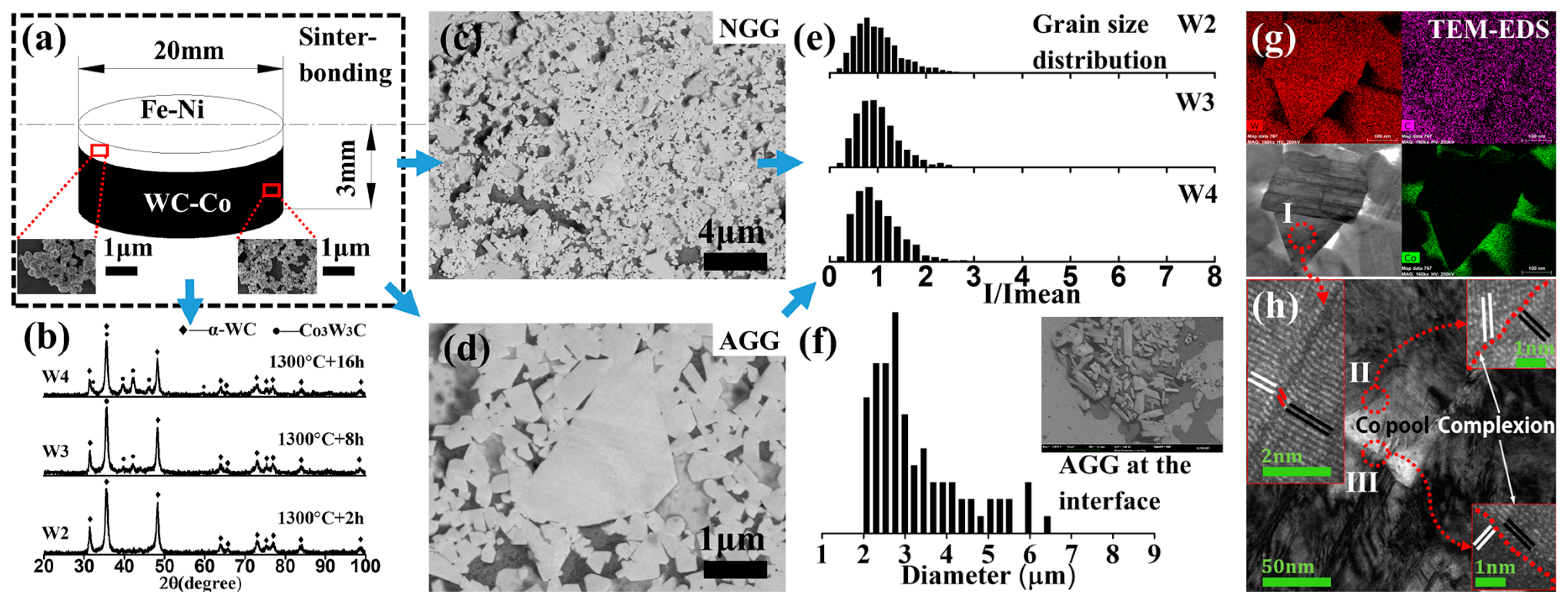
2.1. Sinterbonding
2.2. Brazing
2.2.1. Background
2.2.2. Joint Design
2.2.3. Processes
2.2.4. Selection of Brazing Filler Metals
2.2.5. Advantages and Application
2.3. Laser Welding
2.3.1. Background
2.3.2. Without Filler Metals
2.3.3. Buffered with Interlayers
2.3.4. Laser–TIG
- High-efficiency process (≥80%);
- Ability to bridge relatively large gaps (≥0.5 mm);
- Slow cooling rates because of lower welding speed and higher heat input;
- Highly reflective materials are generally easy to weld [74]. Laser/TIG hybrid welding of cemented carbide to steels followed the wetting mechanism.
2.4. TIG Welding
2.5. Diffusion Bonding
- Temperature is below the melting point.
- Loads producing coalescence of contacting surfaces are below those that would lead to macroscopic deformation.
- Interlayer (foil or coating) can be used as a bonding aid.
2.6. Electron-Beam Welding
2.7. MIG Welding
2.8. Friction Welding
2.9. Others
3. Existing Main Issues, Corresponding Solutions, and Future Work
4. Conclusions
- (1)
- Conventional methods, such as sinter-bonding and vacuum brazing, are the most common approaches because of the vacuum environment, good wettability, and low cost, which are particularly well suited for thicker cemented carbides with lower cobalt contents.
- (2)
- High-efficiency welding processes, such as laser welding, are the most promising joining methods and are better suited for thinner cemented carbides with increased cobalt contents (≥20%). A laser beam can be positioned on the steel side and follows the dip soldering mechanism. A laser beam can also be placed on the cemented carbide side and on top of the middle interlayer.
- (3)
- The coalescence of the melting steels, “soft” binders, and hard carbides (dissolved) is believed to be a possible factor controlling the metallurgical joining. At the collapsed and recreated interface, the higher- and lower-temperature borders of the fusion boundary region are defined by the melting point of the hard carbide and the melting point of the binders.
Author Contributions
Funding
Acknowledgments
Conflicts of Interest
References
- Schröter, K. Hard-Metal Alloy and the Process of Making Same. U.S. Patent US67176423, 31 October 1923. [Google Scholar]
- Lifshitz, I.M.; Slyozov, V.V. The kinetics of precipitation from supersaturated solid solutions. J. Phys. Chem. Solids 1996, 19, 35–50. [Google Scholar] [CrossRef]
- García, J.; Ciprés, V.C.; Blomqvist, A.; Kaplan, B. Cemented carbide microstructures: A review. Int. J. Refract. Met. Hard Mater. 2019, 80, 40–68. [Google Scholar] [CrossRef]
- Fang, Z.Z.; Wang, X.; Ryu, T.; Hwang, K.S.; Sohn, H.Y. Synthesis, sintering, and mechanical properties of nanocrystalline cemented tungsten carbide—A review. Int. J. Refract. Met. Hard Mater. 2009, 27, 288–299. [Google Scholar] [CrossRef]
- Ortner, H.; Kolaska, H.; Ettmayer, P. The history of the technological progress of hardmetals. Int. J. Refract. Met. Hard Mater. 2014, 44, 148–159. [Google Scholar] [CrossRef]
- ISO 4499-2:2008 Hardmetals—Metallographic Determination of Microstructure—Part 2: Measurement of WC Grain Size. 2008. Available online: https://www.iso.org/standard/43501.html (accessed on 24 October 2019).
- Pan, Y.; Xiong, H.; Li, Z.; Long, X. Synthesis of WC-Co composite powders with two-step carbonization and sintering performance study. Int. J. Refract. Met. Hard Mater. 2019, 81, 127–136. [Google Scholar] [CrossRef]
- Fernandes, C.M.; Senos, A.M.R. Cemented carbide phase diagrams: A review. Int. J. Refract. Met. Hard Mater. 2011, 29, 405–418. [Google Scholar] [CrossRef]
- ASM International. Cemented carbides. In ASM Handbook Volume 9: Metallography and Microstructures; ASM International, the Materials Information Society: Novelty, OH, USA, 2000; pp. 273–278. [Google Scholar]
- Geach, G.A. The theory of sintering. Prog. Met. Phys. 1953, 4, 174–204. [Google Scholar] [CrossRef]
- Shaler, A.J.; Wulff, J. Mechanism of sintering. Ind. Eng. Chem. 1948, 40, 838–842. [Google Scholar] [CrossRef]
- Kuczynski, G.C. The mechanism of densification during sintering of metallic particles. Acta Metall. 1956, 4, 58–61. [Google Scholar] [CrossRef]
- Jones, W.D. Mechanism of sintering. Acta Metall. 1959, 7, 222–223. [Google Scholar] [CrossRef]
- Rockland, J.G.R. The determination of the mechanism of sintering. Acta Metall. 1967, 15, 277–286. [Google Scholar] [CrossRef]
- Michalski, A.; Rosiński, M. Sintering diamond/cemented carbides by the pulse plasma sintering method. J. Am. Ceram. Soc. 2008, 91, 3560–3565. [Google Scholar] [CrossRef]
- Rodelas, J.; Hilmas, G.; Mishara, R.S. Sinterbonding cobalt-cemented tungsten carbide to tungsten heavy alloys. Int. J. Refract. Met. Hard Mater. 2009, 27, 835–841. [Google Scholar] [CrossRef]
- Kitiwan, M.; Goto, T. Fabrication of tungsten carbide–diamond composites using SiC-coated diamond. Int. J. Refract. Met. Hard Mater. 2019, 85, 105053. [Google Scholar] [CrossRef]
- Michalski, A.; Cymerman, K.; Rasiński, M. Microstructure of the cBN/WC6Co composite produced by the pulse plasma sintering (PPS) method. Int. J. Refract. Met. Hard Mater. 2015, 50, 197. [Google Scholar] [CrossRef]
- Rosiński, M.; Kruszewski, M.J.; Michalski, A.; Fortuna-Zaleśna, E.; Ciupiński, Ł.; Kurzydłowski, K.J. W/steel joint fabrication using the pulse plasma sintering (PPS) method. Fusion Eng. Des. 2011, 86, 2573–2576. [Google Scholar] [CrossRef]
- Kruszewski, M.J.; Ciupiński, Ł.; Rosiński, M.; Michalski, A.; Kurzydłowski, K.J. Pulse plasma sintering of a tungsten/steel divertor module. Fusion Eng. Des. 2013, 88, 9–10. [Google Scholar] [CrossRef]
- Rödiger, K.; Dreyer, K.; Gerades, T.; Willert-Porada, M. Microwave sintering of hardmetals. Int. J. Refract. Met. Hard Mater. 1998, 16, 409–416. [Google Scholar] [CrossRef]
- Guo, Y.J.; Gao, B.X.; Liu, G.W.; Zhou, T.T.; Qiao, G.J. Effect of temperature on the microstructure and bonding strength of partial transient liquid phase bonded WC–Co/40Cr joints using Ti/Ni/Ti interlayers. Int. J. Refract. Met. Hard Mater. 2015, 51, 250–257. [Google Scholar] [CrossRef]
- Maizza, G.; Cagliero, R.; Iacobone, A.; Montanari, R.; Varone, A.; Mezzi, A.; Kaciulis, S. Study of steel-WC interface produced by solid-state capacitor discharge sinter-welding. Surf. Interface Anal. 2016, 48, 538–542. [Google Scholar] [CrossRef]
- Wang, X.N.; Zhou, D.R.; Xu, P.Q. The WC-Co/Fe–Ni interface: Effect of holding time on the microstructure, grain size and grain growth mechanism. Ceram. Int. 2019, 45, 23320–23327. [Google Scholar] [CrossRef]
- Schröter, K.; Wolff, H. Tool and Method of Making the Same. U.S. Patent US2019934, 29 May 1930. [Google Scholar]
- Gilliland, R.G.; Adams, C.M. Improved brazing methods for tungsten carbide tool bits. Weld. J. 1971, 50, 267–274. [Google Scholar]
- Cole, N.C.; Gilliland, R.G.; Slaughter, G.M. Weldability of tungsten and its alloys. Weld. J. 1971, 49, 419–426. [Google Scholar]
- Thorsen, K.A.; Fordsmand, H.; Praestgaard, P.L. An explanation of wettability problem when brazing cemented carbides. Weld. J. 1984, 63, 308–315. [Google Scholar]
- Pieczara, A.; Piotrowski, T.; Leśniewski, W.; Wawrylak, M.; Wieliczko, P. The impact of brazing parameters on the strength of a WC/Co-filler metal-steel joint. Probl. Eksploat. 2015, 3, 59–64. [Google Scholar]
- Voiculescu, I.; Geanta, V.; Binchiciu, H.; Iovanas, D.; Stefanoiu, R. Dissimilar brazed joints between steel and tungsten carbide. In IOP Conference Series: Materials Science and Engineering; IOP Publishing: Bristol, UK, 2017; Volume 209. [Google Scholar]
- Amelzadeh, M.; Mirsalehi, S.E. Influence of braze type on microstructure and mechanical behavior of WC-Co/steel dissimilar joints. J. Manuf. Process. 2018, 36, 450–458. [Google Scholar] [CrossRef]
- Ji, H.; Li, M.; Lu, Y.; Wang, C. Mechanical properties and microstructures of hybrid ultrasonic resistance brazing of WC-Co/BeCu. J. Mater. Process. Technol. 2012, 212, 1885–1891. [Google Scholar] [CrossRef]
- Tillmann, W.; Sievers, N. Feasibility study of fluxless brazing cemented carbides to steel. In IOP Conference Series: Materials Science and Engineering; IOP Publishing: Bristol, UK, 2017; Volume 181. [Google Scholar]
- Cheniti, B.; Miroud, D.; Badji, R.; Allou, D.; Csanádi, T.; Fides, M.; Hvizdoš, P. Effect of brazing current on microstructure and mechanical behavior of WC-Co/AISI 1020 steel TIG brazed joint. Int. J. Refract. Met. Hard Mater. 2017, 64, 210–218. [Google Scholar] [CrossRef]
- Zhang, X.; Liu, G.; Tao, J.; Shao, H.; Fu, H.; Pan, T.; Qiao, G. Vacuum brazing of WC-8Co cemented carbides to carbon steel using pure Cu and Ag-28Cu as filler metal. J. Mater. Eng. Perform. 2017, 26, 488–494. [Google Scholar] [CrossRef]
- Barrena, M.I.; de Salazar, J.M.G.; Gómez-Vacas, M. Numerical simulation and experimental analysis of vacuum brazing for steel/cermet. Ceram. Int. 2014, 40, 10557–10563. [Google Scholar] [CrossRef]
- Chen, H.; Feng, K.; Xiong, J.; Guo, Z. Characterization and stress relaxation of the functionally graded WC–Co/Ni component/stainless steel joint. J. Alloys Compd. 2013, 557, 18–22. [Google Scholar] [CrossRef]
- Chen, H.; Feng, K.; Wei, S.; Xiong, J.; Guo, Z.; Wang, H. Microstructure and properties of WC–Co/3Cr13 joints brazed using Ni electroplated interlayer. Int. J. Refract. Met. Hard Mater. 2012, 33, 70–74. [Google Scholar] [CrossRef]
- Li, Y.; Zou, Z.; Holly, X.; Feng, T.; Wang, X. A study on microstructure in the brazing interface of WC–TiC–Co hard alloys. Int. J. Refract. Met. Hard Mater. 2002, 20, 169–173. [Google Scholar]
- Lee, W.B.; Kwon, B.D.; Jung, S.B. Effects of Cr3C2 on the microstructure and mechanical properties of the brazed joints between WC–Co and carbon steel. Int. J. Refract. Met. Hard Mater. 2006, 24, 215–221. [Google Scholar] [CrossRef]
- Lee, W.B.; Kwon, B.D.; Jung, S.B. Effect of bonding time on joint properties of vacuum brazed WC–Co hard metal/carbon steel using stacked Cu and Ni alloy as insert metal. Mater. Sci. Technol. 2004, 20, 1474–1478. [Google Scholar] [CrossRef]
- Sui, Y.; Luo, H.; Lv, Y.; Wei, F.; Qi, J.; He, Y.; Meng, Q.; Sun, Z. Influence of brazing technology on the microstructure and properties of YG20C cemented carbide and 16Mn steel joints. Weld. World 2016, 60, 1269–1275. [Google Scholar] [CrossRef]
- Jiang, C.; Chen, H.; Zhao, X.; Qiu, S.; Han, D.; Gou, G. Microstructure and mechanical properties of brazing bonded WC-15Co/35CrMo joint using AgNi/CuZn/AgNi composite interlayers. Int. J. Refract. Met. Hard Mater. 2018, 70, 1–8. [Google Scholar] [CrossRef]
- Li, Y.; Zhu, Z.; He, Y.; Chen, H.; Jiang, C.; Han, D.; Li, J. WC particulate reinforced joint by ultrasonic-associated brazing of WC-Co/35CrMo. J. Mater. Process. Technol. 2016, 238, 15–21. [Google Scholar] [CrossRef]
- Triantafyllou, G.; Irvine, J.T.S. Wetting and interactions of Ag–Cu–Ti and Ag–Cu–Ni alloys with ceramic and steel substrates for use as sealing materials in a DCFC stack. J. Mater. Sci. 2016, 51, 1766–1778. [Google Scholar] [CrossRef]
- Feng, J.; Zhang, L.X. Interface structure and mechanical properties of the brazed joint of TiC cermet and steel. J. Eur. Ceram. Soc. 2006, 26, 1287–1292. [Google Scholar] [CrossRef]
- Laansoo, A.; Kübarsepp, J.; Vainola, V.; Viljus, M. Induction brazing of cermets to steel. Estonian J. Eng. 2012, 18, 232–242. [Google Scholar] [CrossRef]
- Northrop, I.T. The joining of tungsten carbide hardmetal to steel. J. S. Afr. Inst. Min. Metall. 1987, 5, 125–135. [Google Scholar]
- Aminov, A.B.; Dubrovsky, K.E. Influence of brazing process parameters on the strength of liquid rocket engine brazed structures. In IOP Conference Series: Materials Science and Engineering; IOP Publishing: Bristol, UK, 2019; Volume 491. [Google Scholar]
- Farrell, K.; Houston, J.T.; Chumley, J.W. Hot cracking in fusion welds in tungsten. Weld. J. 1970, 49, 132–137. [Google Scholar]
- Lessman, G.G.; Gold, R.E. The weldability of tungsten base alloys. Weld. J. 1969, 48, 528–542. [Google Scholar]
- Einstein, A. Zur Quantentheorie der Strahlung (On the quantum theory of radiation). Phys. Z. 1917, 18, 121–128. [Google Scholar]
- Conrad, M.B. High power laser welding. Opt. Eng. 1978, 17, 173210. [Google Scholar]
- Arata, Y. Plasma, Electron and Laser Beam Technology-Development and Use in Material Processing; American Society for Metals: Metals Park, OH, USA, 1986; pp. 378–396. [Google Scholar]
- Bagger, C.; Olsen, F.O. Review of laser hybrid welding. J. Laser Appl. 2005, 17, 2–14. [Google Scholar] [CrossRef]
- Cao, X.; Jahazi, M.; Immarigeon, J.P.; Wallace, W. A review of laser welding techniques for magnesium alloys. J. Mater. Process. Technol. 2006, 171, 188–204. [Google Scholar] [CrossRef]
- Xu, P.Q.; Ren, J.W.; Zhang, P.L.; Gong, H.Y.; Yang, S.L. Analysis of formation and interfacial WC dissolution behavior of WC-Co/Invar laser-TIG welded joints. J. Mater. Eng. Perform. 2013, 22, 613–623. [Google Scholar] [CrossRef]
- Sandig, S.; Wiesner, P.; Greitmann, M.; Deutschmann, G. Laser welding of hard metal components onto steel. DVS Ber. 1994, 163, 326. [Google Scholar]
- Tian, N.; Yang, Y. Study of laser molten welding of cemented carbides and steel. In Proceedings of the Laser Processing of Materials and Industrial Applications, International Society for Optics and Photonics, Beijing, China, 4–7 November 1996; Volume 2888, pp. 185–193. [Google Scholar]
- Miranda, R.M.; Quintino, L.; Costa, A.; Pina, J.C.P.; Rosa, T.; Catarino, P.; Rodrigues, J.P. Analysis of different laser welding processes for joining hardmetals to steel. Weld. World 2008, 52, 42–51. [Google Scholar] [CrossRef]
- Zhou, D.R.; Cui, H.C.; Xu, P.Q.; Lu, F.G. Tungsten carbide grain size computation for WC-Co dissimilar welds. J. Mater. Eng. Perform. 2016, 25, 2500–2510. [Google Scholar] [CrossRef]
- Xu, P.; Zhou, D.R.; Li, L. Fiber laser welding of WC-Co and carbon steel dissimilar materials. Weld. J. 2017, 96, 1–10. [Google Scholar]
- Costa, A.P.; Quintino, L.; Greitmann, M. Laser beam welding hard metals to steel. J. Mater. Process. Technol. 2003, 141, 163–173. [Google Scholar] [CrossRef]
- Barbatti, C.; Garcia, J.; Liedl, G.; Pyzalla, A. Joining of cemented carbides to steel by laser beam welding. Materialwissensch. Werkst. 2007, 38, 907–914. [Google Scholar] [CrossRef]
- Guillaume, C.E. Recherches sur les aciers au nickel. Dilatations aux temperatures elevees; resistance electrique. CR Acad. Sci. 1897, 125, 235–238. [Google Scholar]
- Weiss, R.J. The origin of the ‘Invar’ effect. Proc. Phys. Soc. 1963, 82, 281–288. [Google Scholar] [CrossRef]
- Schilfgaarde, M.; Abrikosov, I.A.; Johansson, B. Origin of the Invar effect in iron–nickel alloys. Nature 1999, 400, 46–49. [Google Scholar] [CrossRef]
- Yu, X.Y.; Zhou, D.R.; Yao, D.J.; Lu, F.G.; Xu, P.Q. Fiber laser welding of WC-Co to carbon steel using Fe-Ni invar as interlayer. Int. J. Refract. Met. Hard Mater. 2016, 56, 76–86. [Google Scholar] [CrossRef]
- Yao, D.J.; Zhou, D.R.; Xu, P.Q.; Lu, F.G. Microstructure and plastic deformation of as-welded Invar fusion zones. Metall. Mater. Trans. A 2017, 48, 2274–2281. [Google Scholar] [CrossRef]
- Callister, W.D., Jr.; Rethwisch, D.G. Materials Science and Engineering: An Introduction, 8th ed.; Wiley, John Wiley & Sons, Inc.: Hoboken, NJ, USA, 2009; pp. 162–189. [Google Scholar]
- Mirski, Z.; Granat, K.; Stano, S. Possibilities of laser-beam joining cemented carbides to steel. Weld. Int. 2016, 30, 187–191. [Google Scholar] [CrossRef]
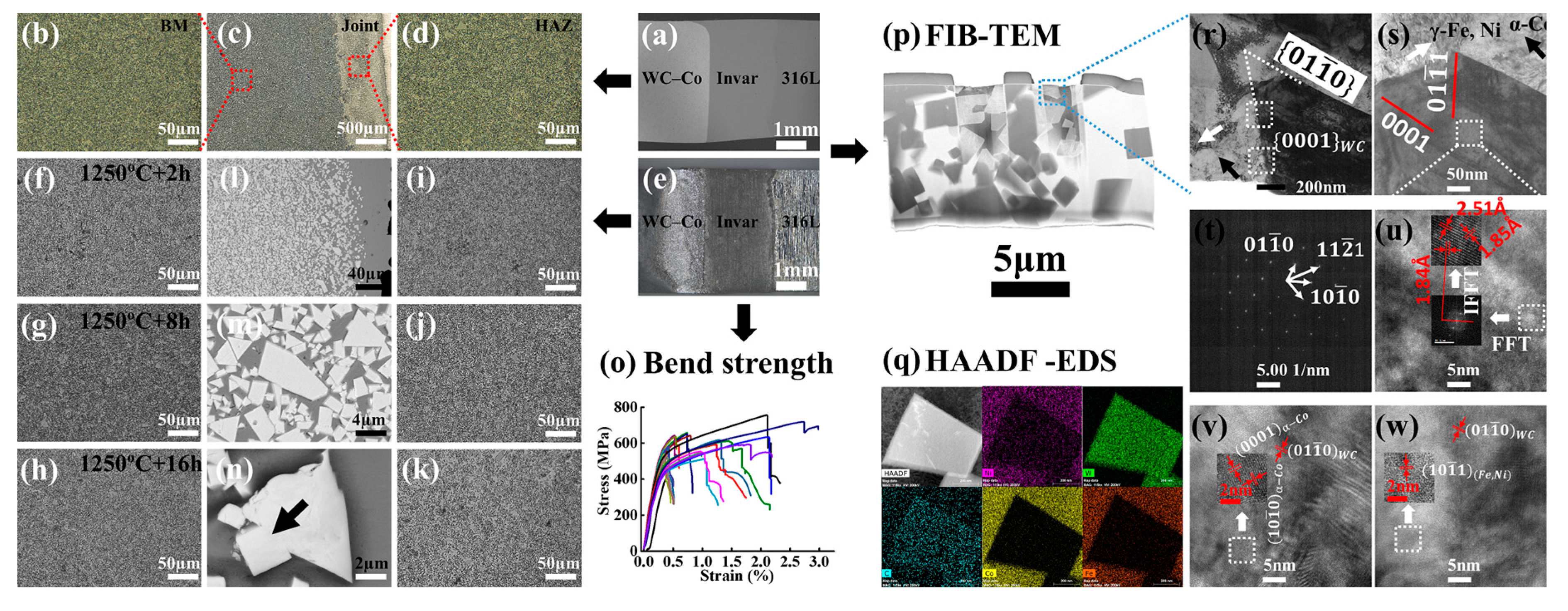
- Yin, G.T.; Xu, P.Q.; Gong, H.Y.; Cui, H.C.; Lu, F.G. Effect of interlayer thickness on the microstructure and strength of WC-Co/Invar/316L steel joints prepared by fibre laser welding. J. Mater. Process. Technol. 2018, 255, 319–332. [Google Scholar] [CrossRef]
- Yin, G.T.; Wang, Y.Y.; Cui, H.C.; Lu, F.G.; Xu, P.Q. Effect of holding time and interlayer’s thickness on the crack initiation and propagation and the dissolving behavior of the heat affected facet WC grains. Int. J. Refract. Met. Hard Mater. 2018, 71, 45–60. [Google Scholar] [CrossRef]
- Song, G.; Diao, Z.; Lv, X.; Liu, L. TIG and laser-TIG hybrid filler wire welding of casting and wrought dissimilar magnesium alloy. J. Manuf. Process. 2018, 34, 204–214. [Google Scholar] [CrossRef]
- Xu, P.Q. Dissimilar welding of WC–Co cemented carbide to Ni42Fe50.9C0.6Mn3.5Nb3 invar alloy by laser-tungsten inert gas hybrid welding. Mater. Des. 2011, 32, 229–237. [Google Scholar] [CrossRef]
- Xu, P.Q.; Li, L. Weld fusion boundary between steel and carbide dissimilar materials. In Proceedings of the AWS Professional Program, FABTECH, Las Vegas, NV, USA, 16–18 November 2016. [Google Scholar]
- Nagatsuka, K.; Sechi, Y.; Miyamoto, Y.; Nakata, K. Characteristics of dissimilar laser-brazed joints of isotropic graphite to WC-Co alloy. Mater. Sci. Eng. B 2012, 177, 520–523. [Google Scholar] [CrossRef]
- Kou, S. Welding Metallurgy, 2nd ed.; John Wiley & Sons, Inc.: Hoboken, NJ, USA, 2003; pp. 13–15. [Google Scholar]
- Miyakoshi, Y.; Takazawa, K.; Tagashira, K.; Kamota, S.; Takahashi, H.; Maruyama, M.; Kanayama, T. Microstructure and strength of interface in joint of WC-40MASS%Co alloy/carbon steel. J. Jpn. Soc. Powder Powder Metall. 1997, 44, 958–962. [Google Scholar] [CrossRef]
- Zhao, X.J.; Yang, D.X.; Wang, H.; Takazawa, K.; Tagashira, K.; Yamamori, H. The eta phases and mechanical properties of TIG welded joints of WC–Co cemented carbide and steel. China Weld. 2004, 13, 56–60. [Google Scholar]
- Zhao, X.J.; Liu, P.T.; Chen, C.H.; Yang, D.X.; Tagashira, K. η phase formation mechanism at cemented carbide YG30/Steel 1045 joints during Tungsten-Inert-Gas arc welding. Mater. Sci. Forum. 2011, 675, 901–904. [Google Scholar] [CrossRef]
- Xu, P.Q.; Zhao, X.J.; Yang, D.X.; Yao, S. Study on filler metal (Ni-Fe-C) during GTAW of WC-30Co to 45″ carbon steel. J. Mater. Sci. 2005, 40, 6559–6564. [Google Scholar]
- Wang, H.; Yang, D.; Zhao, X.; Chen, C.; Wang, Q. Microstructure and bend strength of WC–Co and steel joints. Sci. Technol. Weld. Join. 2005, 10, 167–168. [Google Scholar] [CrossRef]
- Zhang, Y.; Pan, J.; Xia, S.; Zhao, X.J.; Chen, C.H. Research on TIG welding of gradient cemented carbide and 45 steel. Weld. Dig. Mach. Manuf. 2018, 5, 17–21. (In Chinese) [Google Scholar]
- Mahnoey, M.W.; Bampton, C.C. Fundamentals of Diffusion Bonding, ASM Handbook, Volume 6A, Welding Fundamentals and Processes; Lienert, T., Siewert, T., Babu, S., Acoff, V., Eds.; ASM International: Novelty, OH, USA, 2011; pp. 217–221. [Google Scholar]
- Cottenden, A.M.; Almond, E.A. Hardmetal interlayed butt joints made by diffusion bonding and pressure bonding. Met. Technol. 1981, 8, 221–233. [Google Scholar] [CrossRef]
- Lamboliev, T.; Valkanov, S.; Atanasova, S. Microstructure embrittlement of hard metal-steel joint obtained under induction heating diffusion bonding. Int. J. Refract. Met. Hard Mater. 2013, 37, 90–97. [Google Scholar] [CrossRef]
- Lemus-Ruiz, J.; Ávila-Castillo, J.J.; García-Estrada, R. WC/Stainless steel joints produced by direct diffusion bonding using a Ni-Foil interlayer. Mater. Sci. Forum. 2007, 560, 53–57. [Google Scholar] [CrossRef]
- Guo, Y.; Wang, Y.; Gao, B.; Shi, Z.; Yuan, Z. Rapid diffusion bonding of WC-Co cemented carbide to 40Cr steel with Ni interlayer: Effect of surface roughness and interlayer thickness. Ceram. Int. 2016, 42, 16729–16737. [Google Scholar] [CrossRef]
- Barrena, M.I.; Gómez de Salazar, J.M.; Merina, N.; Matesanz, L. Characterization of WC–Co/Ti6Al4V diffusion bonding joints using Ag as interlayer. Mater. Charact. 2008, 59, 1407–1411. [Google Scholar] [CrossRef]
- Barrena, M.I.; Gómez de Salazar, J.M.; Matesanz, L. Interfacial microstructure and mechanical strength of WC–Co/90MnCrV8 cold work tool steel diffusion bonded joint with Cu/Ni electroplated interlayer. Mater. Des. 2010, 31, 3389–3394. [Google Scholar] [CrossRef]
- Cai, Q.; Liu, W.; Ma, Y.; Zhu, W.; Pang, X. Influence of intermetallic compounds on the microstructure and strength properties of diffusion bonded W–steel joints using Ti/Ni composite interlayer. Fusion Eng. Des. 2018, 132, 110–118. [Google Scholar] [CrossRef]
- Feng, K.; Chen, H.; Xiong, J.; Guo, Z. Investigation on diffusion bonding of functionally graded WC–Co/Ni composite and stainless steel. Mater. Des. 2013, 46, 622–626. [Google Scholar] [CrossRef]
- Andreatta, F.; Matesanz, L.; Akita, A.H.; Paussa, L.; Fedrizzi, L.; Fugivara, C.S.; Gómez de Salazar, J.M.; Benedetti, A.V. SAE 1045 steel/WC–Co/Ni–Cu–Ni/SAE 1045 steel joints prepared by dynamic diffusion bonding: Microelectrochemical studies in 0.6M NaCl solution. Electrochim. Acta 2009, 55, 551–559. [Google Scholar] [CrossRef]
- Hochanadel, P.W.; Elmer, I.W.; Lachenberg, K.; Burgardt, P.; Kautz, D.D. Electron Beam Welding, ASM Handbook, Volume 6A, Welding Fundamentals and Processes; Lienert, T., Siewert, T., Babu, S., Acoff, V., Eds.; ASM International: Novelty, OH, USA, 2011; pp. 514–521. [Google Scholar]
- Zhao, X.J.; Yang, D.X.; Wang, H.; Takazawa, K.; Tagashira, K.; Yamamori, H. Microstructure of electron beam weld joints between cemented carbide YG30 and carbon steel. Mater. Mech. Eng. 2005, 29, 21–26. (In Chinese) [Google Scholar]
- Chen, G.; Zhang, B.; Wu, Z.; Mao, W.; Feng, J. Electron beam welding–brazing of hard alloy to steel with Ni–Fe intermediate. Int. J. Refract. Met. Hard Mater. 2013, 40, 58–63. [Google Scholar] [CrossRef]
- Chen, G.; Shu, X.; Liu, J.; Zhang, B.; Zhang, B.; Feng, J. Electron beam hybrid welding-brazing of WC-Co/40Cr dissimilar materials. Ceram. Int. 2019, 45, 7821–7829. [Google Scholar] [CrossRef]
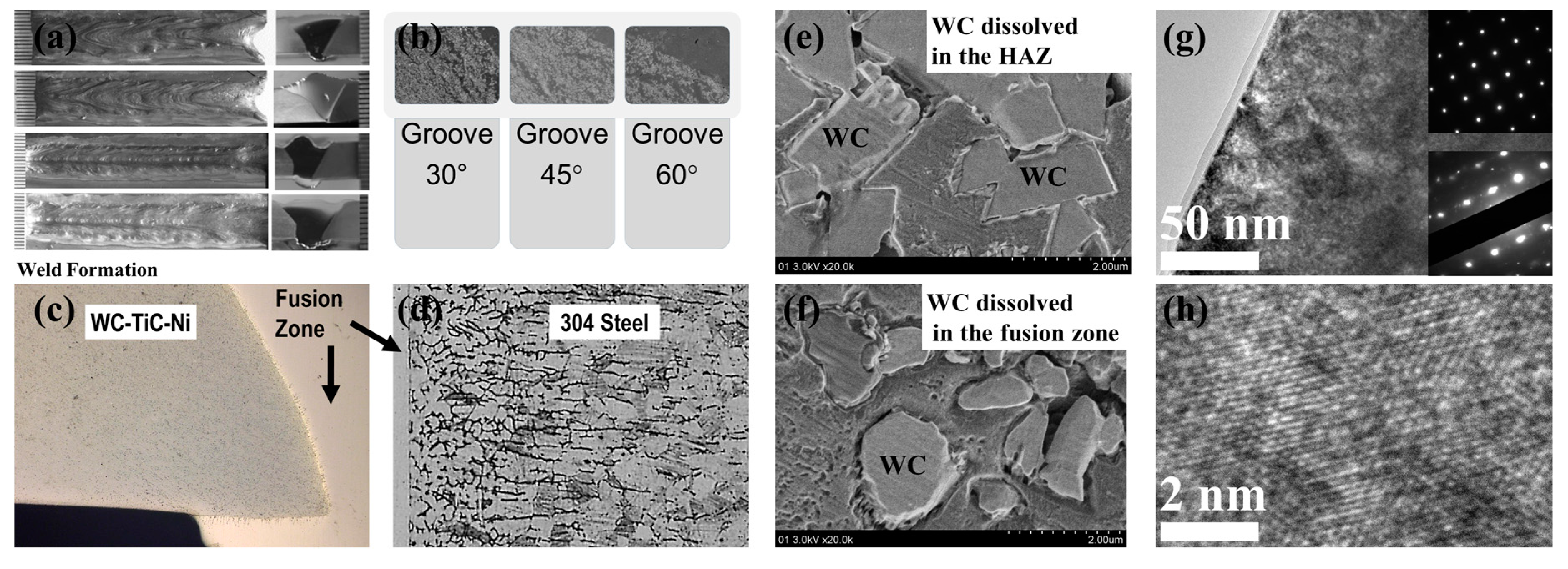
- Ying, G.T.; Gong, H.Y.; Xu, P.Q. Migration Behavior of Tungsten carbide in the dissimilar joints of WC-TiC-Ni/304 stainless steel using robotic MIG welding. In Transactions on Intelligent Welding Manufacturing; Springer: Singapore, 2018; pp. 145–163. [Google Scholar]
- Nandan, R.; DebRoy, T.; Bhadeshia, H.K.D.H. Recent advances in friction stir welding—Process, weldment, structure and properties. Prog. Mater. Sci. 2008, 53, 980–1023. [Google Scholar] [CrossRef]
- Elmer, J.W.; Kautz, D.D. Fundamentals of Friction Welding, ASM Handbook, Volume 6A, Welding Fundamentals and Processes; Lienert, T., Siewert, T., Babu, S., Acoff, V., Eds.; ASM International: Novelty, OH, USA, 2011; pp. 179–196. [Google Scholar]
- Okita, K.; Aritoshi, M.; Kuwabara, K.; Matsui, M.; Takami, C.; Kajino, H.; Tsuda, K. Friction welding of cemented carbide alloy to tool steel. Weld. Int. 1997, 11, 257–263. [Google Scholar] [CrossRef]
- Avettand-Fènoël, M.N.; Nagaoka, T.; Fujii, H.; Taillard, R. Characterization of WC/12Co cermet–steel dissimilar friction stir welds. J. Manuf. Process. 2018, 31, 139–155. [Google Scholar] [CrossRef]
- Avettand-Fènoël, M.N.; Nagaoka, T.; Fujii, H.; Taillard, R. Effect of a Ni interlayer on microstructure and mechanical properties of WC-12Co cermet/SC45 steel friction stir welds. J. Manuf. Process. 2019, 40, 1–15. [Google Scholar] [CrossRef]
- Sánchez Egea, A.J.; Rodríguez, A.; Celentano, D.; Calleja, A.; López de Lacalle, L.N. Joining metrics enhancement when combining FSW and ball-burnishing in a 2050 aluminium alloy. Surf. Coat. Technol. 2019, 367, 327–335. [Google Scholar] [CrossRef]
- Olvera, D.; López de Lacalle, L.N.; Urbikain, G.; Lamikiz, A.; Rodal, P.; Zamakona, I. Hole making using ball helical milling on titanium alloys. Mach. Sci. Technol. 2012, 16, 173–188. [Google Scholar] [CrossRef]
- Xian, G.; Xiong, J.; Zhao, H.; Fan, H.; Li, Z.; Du, H. Evaluation of the structure and properties of the hard TiAlN-(TiAlN/CrAlSiN)-TiAlN multiple coatings deposited on different substrate materials. Int. J. Refract. Met. Hard Mater. 2019, 85, 105056. [Google Scholar] [CrossRef]
- Da Cunha, T.V.; Bohórquez, C.E. Ultrasound in arc welding: A review. Ultrasonics 2015, 56, 201–209. [Google Scholar] [CrossRef] [PubMed]
- Chai, B.; Xiong, J.; Guo, Z.; Liu, J.; Ni, L.; Xiao, Y.; Chen, C. Structure and high temperature wear characteristics of CVD coating on HEA-bonded cermet. Ceram. Int. 2019, 45, 19077–19085. [Google Scholar] [CrossRef]
- Kumar, S.; Wu, C.S.; Padhy, G.K.; Ding, W. Application of ultrasonic vibrations in welding and metal processing: A status review. J. Manuf. Process. 2017, 26, 295–322. [Google Scholar] [CrossRef]
- Penilla, E.H.; Devia-Cruz, L.F.; Wieg, A.T.; Martinez-Torres, P.; Cuando-Espitia, N.; Sellappan, P.; Kodera, Y.; Aguilar, G.; Garay, J.E. Ultrafast laser welding of ceramics. Science 2019, 365, 803–808. [Google Scholar] [CrossRef] [PubMed]


| Hard Metals | Counterpart | Load (MPa) | Sintering Method | Temperature (°C) | Mechanical Properties (GPa) | Reference |
|---|---|---|---|---|---|---|
| WC–Co | Diamond | - | PPS | 1000 | 23 | [15] |
| WC–6Co | W–3.5Ni–1.5Fe | 30 | Uniaxial Hot-Pressing | 1325 | - | [16] |
| WC | Diamond (SiC) | 130 | SPS | 1190–1600 | 30.5 | [17] |
| WC–6Co | cBN | 100 | PPS | 1150 | - | [18] |
| W | Eurofer97 steel | - | PPS | 1000 | - | [19] |
| W–La2O3 | P91 | - | PPS | 800 | - | [20] |
| WC | Co | - | Microwave Sintering | - | - | [21] |
| WC–10Co | 40Cr | 0.3 | PTLP | 950–1100 | - | [22] |
| WC–12Co | AISI M2 | - | CDSW | - | - | [23] |
| WC–20Co | Invar | - | Liquid-phase sintering | 1350 | - | [24] |
| Composition | Brazing Conditions | Thickness (mm) | Body Material (1) | Body Material (2) | Temperature (°C) | Reference |
|---|---|---|---|---|---|---|
| Cu-Borax/Mo/Cu-Borax/ | - | - | Hard metal | Steel or iron | 1100 | [25] |
| AuNi, Silver, AgCu, Copper | Vacuum | 0.127 | WC–6Co | 4340 | 810–1100 | [26] |
| WRe | GTA braze | 0.25 | GE–15 | - | - | [27] |
| CuAg, OFHC Copper | Sinter, hydrogen | - | WC–TiC/TaC–Co | - | 1400 | [28] |
| CuMnCo | Induction, Argon | 0.2/0.3 | B30 | 40HM | 1040–1120 | [29] |
| AgCuP | Flame, flux | - | WC | steel | 470–725 | [30] |
| AgCuZnCd | Flame, flux | - | W–Co–Ti | AISI 4145 | 710–980 | [31] |
| AgCuZnCd | Ultrasound, flux | 0.2 | WC–15Co | Be–Cu | 640–750 | [32] |
| Zinc, AlSi-alloy | Ultrasound, fluxless | - | K10 | T11302 | - | [33] |
| AgZnCuNiMn | GTA braze | - | WC–10Co | AISI 1020 | 1300 | [34] |
| AgCu | Vacuum | 0.8/2 | WC–8Co | SAE1045 | 1100/850 | [35] |
| AgZnCuNi | Vacuum | 0.3 | WC–10Co | 90MnCrV8 | 850 | [36] |
| CuZn(Ni) | - | - | WC-Co/Ni | 410 | - | [37] |
| CuZn | Vacuum | 0.2 | WC–8Co | 3Cr13 | 1060–1100 | [38] |
| CuZnNi | Vacuum | - | WC–TiC–Co | - | 940–960 | [39] |
| CuNi | Vacuum | - | WC–Co | Carbon steel | - | [40] |
| CuNi | Vacuum | 0.1/0.04 | WC–8Co | S45C | 1050 | [41] |
| CuMnZn | Vacuum | 0.2 | WC–20Co | 16Mn | 940–980 | [42] |
| AgNi/CuZn/AgNi | Induction, flux | 0.12 | WC–15Co | 35CrMo | 710–770 | [43] |
| Hard Metals | Counterparts | Inserts | Thickness (mm) | Lasers | Reference |
|---|---|---|---|---|---|
| L135 YG15 | C45 6542 | - | 1.5/3 | CO2 Laser | [59] |
| K10 K40 | 1.7182 | - | 2.5 | CO2 Laser Nd/YAG | [60] |
| YG20 | C45 | - | 2/3/4 | Fiber Laser | [62] |
| K10 K40 | Hypoeutectoid steel | - | 2.5–2.9 | CO2 Laser Nd/YAG Fiber Laser | [63] |
| HM1-4 | 1.1231 | - | 1 | Nd/YAG | [64] |
| YG20 | C45 | Invar | 3/4 | Fiber Laser | [68] [69] |
| H10S G10 | C45 | Cu–Ag–Ni | / | Disk Laser | [71] |
| YG30 | C45 | - | 6 | CO2 Laser | [75] [76] |
| K10 | Graphite | Cu–Ag–Ti | 10 × 10 × 2 5 × 5 × 3.5 3 × 3 × 0.1 | YAG Laser Laser Diode (LD) laser | [77] |
© 2019 by the authors. Licensee MDPI, Basel, Switzerland. This article is an open access article distributed under the terms and conditions of the Creative Commons Attribution (CC BY) license (http://creativecommons.org/licenses/by/4.0/).
Share and Cite
Ma, B.; Wang, X.; Chen, C.; Zhou, D.; Xu, P.; Zhao, X. Dissimilar Welding and Joining of Cemented Carbides. Metals 2019, 9, 1161. https://doi.org/10.3390/met9111161
Ma B, Wang X, Chen C, Zhou D, Xu P, Zhao X. Dissimilar Welding and Joining of Cemented Carbides. Metals. 2019; 9(11):1161. https://doi.org/10.3390/met9111161
Chicago/Turabian StyleMa, Binghui, Xiaonan Wang, Chunhuan Chen, Dongran Zhou, Peiquan Xu, and Xiujuan Zhao. 2019. "Dissimilar Welding and Joining of Cemented Carbides" Metals 9, no. 11: 1161. https://doi.org/10.3390/met9111161
APA StyleMa, B., Wang, X., Chen, C., Zhou, D., Xu, P., & Zhao, X. (2019). Dissimilar Welding and Joining of Cemented Carbides. Metals, 9(11), 1161. https://doi.org/10.3390/met9111161