Article

Influence of Subflux Turbulence Controller and Ladle Shroud Asymmetric Using on Hydrodynamic Conditions in One Strand Slab Tundish

Department of Metals Extraction and Recirculation, Faculty of Production Engineering and Materials Technology, Czestochowa University of Technology, Armii Krajowej 19 ave, 42-200 Czestochowa, Poland
Metals 2019, 9(1), 68; https://doi.org/10.3390/met9010068
Submission received: 19 December 2018 / Revised: 3 January 2019 / Accepted: 9 January 2019 / Published: 11 January 2019
(This article belongs to the Special Issue Optimization of Industrial Casting Processes)

Abstract

:
The tundish plays a key role in the process of continuous steel casting (CSC), as it ensures a stable flow of steel to the mould. Therefore, particular attention is paid to the behavior of liquid steel in the tundish. A wedge-shape tundish with a nominal capacity of 30 tons was tested. The present study has examined different variants of subflux turbulence controller (STC) and ladle shroud (LS) positions relative to one another. For the designed continuous casting variants with the modified tundish pouring zones, numerical simulations of liquid steel behavior were performed. From the computer simulations results, motion, velocity magnitude, and temperature of liquid steel were obtained. Moreover the shares of stagnant volume flow, dispersed plug flow, well-mixed volume flow and transient zone were calculated. It is possible to effectively modify the hydrodynamic conditions by appropriate selection the position of the STC and LS.

1. Introduction

The tundish plays a key role in the process of continuous steel casting (CSC), as it ensures a stable inflow of steel to the mould. Slabs formed in this process should exhibit the required quality, which is determined by tundish operation, among other factors. The quality of a slabs is determined primarily by the steel overheating temperature and the level of impurities in the form of non-metallic inclusions (NMIs) and gases. The impurity level prescribed for a given steel grade is achieved during refining in the ladle furnace. While the tundish should either maintain or reduce the impurity level achieved in the ladle furnace. Therefore, particular attention is paid to the behavior of the tundish powder and the ceramic tundish working layer, which may cause the formation of additional non-metallic inclusions. Advanced tundish stations are equipped with plasma reheating or circulatory degassing installations [1,2]. While as standard, tundishes are furnished with flow control devices (FCD), NMI flotation intensifying or chemical and thermal homogenization enhancing devices. Classic flow control devices include dams, weirs, subflux turbulence controllers (STC), or argon curtains [3,4,5,6,7,8,9,10,11,12,13,14]. Often, tundishes are equipped with ceramic filters, or special chambers to induce rotary motion [15,16]. To modify the liquid steel motion in a contactless manner, electromagnetic stirring is used [17,18,19]. One of the most common FCDs is a STC installed in the pouring zone. The main purpose of the STC is to suppress the turbulent flow beyond the tundish pouring zone. The STC is a device in the form of a flanged box. The internal working part of the STC is formed by walls that often have a varying angle of inclination relative to the STC bottom. As standard, an STC is installed in the axis of the feeding stream flowing out of the steelmaking ladle. However, in industrial conditions, it may happen that the steel stream does not flow perfectly into the STC’s centre due an incorrect installation of the STC in the tundish or the ladle shroud (LS) in the steelmaking ladle. Therefore, the description of hydrodynamic conditions developing in a tundish with a non-standard inflow of steel to the STC seems fully justified. It is all the more so because, as has been demonstrated in studies [20,21,22], an eccentric position of the ladle shroud or it not being perpendicular to the steelmaking ladle bottom causes a change to the liquid steel flow pattern in the tundish working space. The present study has examined different variants of STC and LS positions relative to one another.

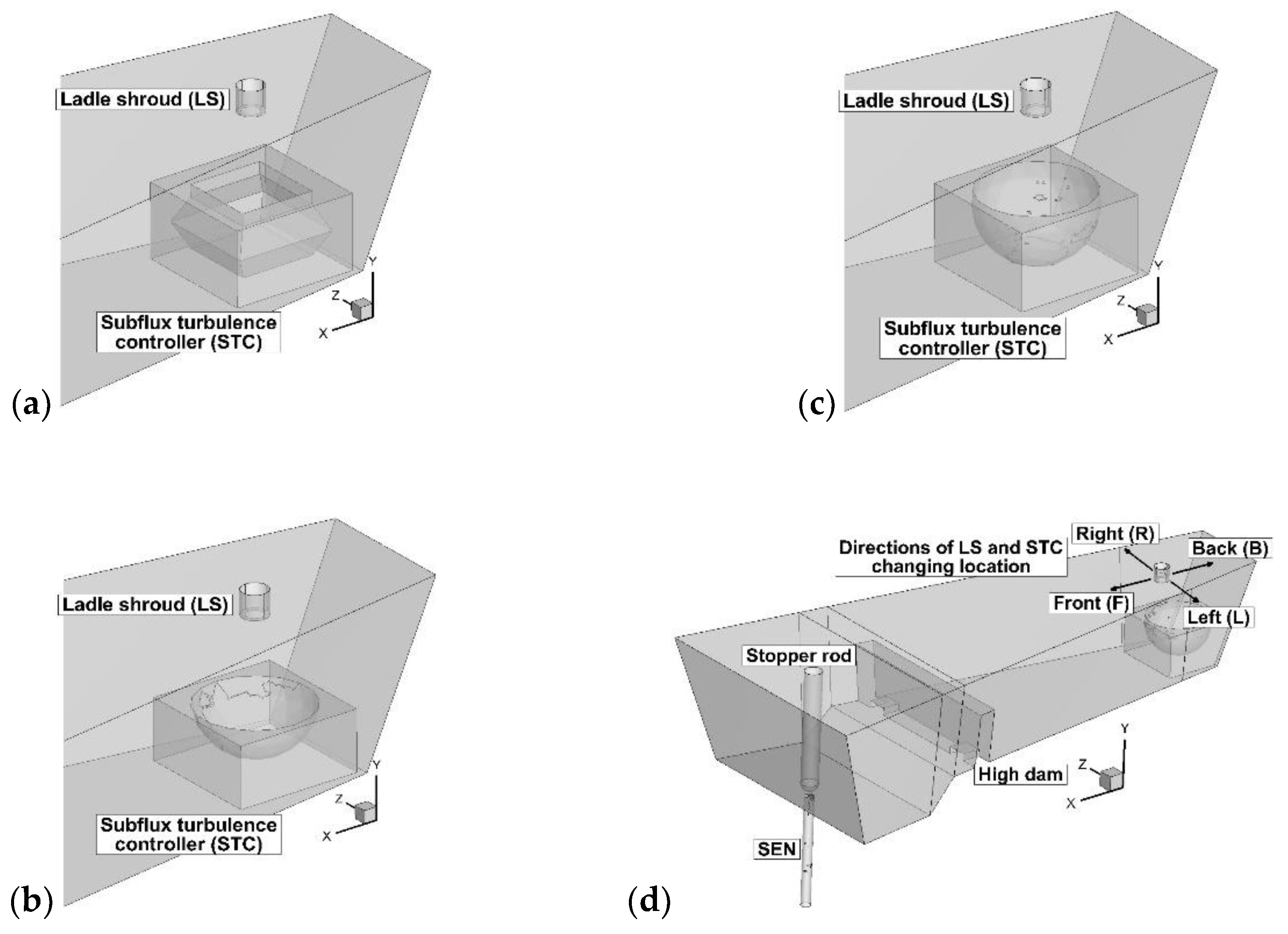
2. Tundish Description and Considered Positions of STC and LS

A wedge-shape tundish with a nominal capacity of 30 tons is used for casting slabs [23]. The inflow of liquid steel to the mould is controlled using a stopper rod system. The steel flows in to the mould through a ceramic submerged entry nozzle. Also between the steelmaking ladle and the tundish the feeding stream is protected by a ladle shroud immersed in the liquid steel at a depth of 0.1 m. In the feeding stream axis, a STC is installed (Figure 1). A detailed description and the dimensions of the STC are provided in reference [24]. STC No. 1 is distinguished by its internal working space being formed of two cones oriented to each other with their bases. The upper cone forms a kind of working flange, which is characteristic of these types of flow control devices. The internal working space of STC No. 2 and 3 has been designed in the form of a sphere. STC No. 2 is characterized by a working space being equal to half of the sphere volume. By contrast, the internal working space of STC No. 3 is deeper, whereby the sphere is truncated in the location of a smaller radius to create a flange form. In the tundish working space immediately before the mould feed zone, a 0.12 m-high dam is mounted (low dam). The mould feed zone has a lowered bottom to minimize the risk of tundish slag entrainment in the final period of the casting sequence. In one of the STC variants, a 0.4 m-high dam was installed (high dam).
Table 1 shows variants of STC and LS arrangement relative to one another, which are examined in the study. At the first testing stage, the position of the STC relative to the ladle shroud was changed. This situation is the simplest to achieve in industrial conditions, not only by an intentional action, but often also due to an accidental failure to meet the guidelines when mounting the STC in the tundish. The possibility of moving the STC relative to the ladle shroud in the case of the tundish under analysis has its limitations resulting from the working volume of the pouring zone. Therefore, the STC was moved by a maximum of 0.15 m towards the rear wall or the stopper rod system and by 0.075 m towards one of the side walls. A restriction concerning the position of the STC relative to the ladle shroud is also the STC working flange that limits the area through which the feeding stream might potentially flow into the STC. That is why STC No. 2 and 3 were characterized by a greater flexibility in terms of STC position relative to the ladle shroud. In the case of the STC being moved towards rear wall, achieving an improvement in hydrodynamic conditions would entail a change in the external shape of the STC. At the second testing stage, the STC was mounted in the position designed for this purpose by default. Only the ladle shroud position changed, which in industrial conditions is obviously much more difficult because of the automatic positioning of the tundish car or ladle turret. At this testing stage, the ladle shroud position was also changed in the range of 0.075–0.15 m. At the last stage of computer simulations, an asymmetric STC mounting relative to the longitudinal tundish axis was tested. Also, the effect of the maximum possible STC and LS displacements towards the rear side wall was tested.

3. Mathematical Model and Methodology

For building the virtual model, the Gambit 2.4 computer program (Ansys, Inc., Canonsburg, PA, USA) was used. The numerical domain included tet/hybrid elements of the Tgrid type. The created virtual tundishes with STC and LS considered positions were composed of computational grid, each with an average number of elements 390,000. The results from authors previous work showed that considered number of elements in the grid was sufficient for prediction macro hydrodynamic conditions in the tundish [23]. Moreover results from numerical simulations obtained for virtual model with similar grid was successfully validated by laboratory and industrial trials [25]. The software program Ansys-Fluent 12.1 (Ansys, Inc., Canonsburg, PA, USA) was used to perform numerical simulations of the behavior of liquid steel during continuous casting of slabs. The basic mathematical model equations describing the fluid flow motion are as follows [26,27]:
ρ t = [ x ( ρ u ) + y ( ρ u ) + z ( ρ u ) ]
t ( ρ u ) = [ x ( ρ u u ) + y ( ρ u u ) + z ( ρ u u ) ] [ p x + p y + p z ] [ x τ + y τ + z τ ] + ρ g
t ( ρ h ) = [ x ( u ρ h ) + y ( u ρ h ) + z ( u ρ h ) ] + x ( k e f f T x ) + y ( k e f f T y ) + ( k e f f T z )
where: g—gravitational acceleration (m/s2), h—enthalpy (J/kg), keff—effective thermal conductivity (W/m·K), p—pressure (Pa), t—time (s), T—temperature (K), u—velocity (m/s), τ—shear stress (Pa), ρ—density (kg/m3), x—coordinate (m), y—coordinate (m), z—coordinate (m).
It is obvious that during steelmaking processes liquid steel behavior like incompressible Newtonian liquid, therefore equation of continuity include only velocity of fluid. Additionally shear stress in the equation of motion is expressed like product of viscosity and velocity of liquid. For the non-isothermal conditions of steel flow through the tundish, the magnitudes of heat fluxes on particular tundish walls and bottom have been determined to be −2600 W/m2, whereas on the regulator walls −1750 W/m2. The losses on the steel free surface are −15,000 W/m2. The heat fluxes were determined on the basis of industrial trials and repeatedly used by many researchers and also tested for consider tundish [28,29,30,31,32,33,34,35,36]. The wall condition with zero tangential stress was assumed on the free steel table surface. User defined scalar (UDS) transport equation were used to calculate the motion of the tracer in the liquid steel. For the description of the turbulence of steel flow through the tundish, the realizable k-ε turbulence model were adopted. For the complete verification of the correctness of the results obtained from the computer simulations, complementary laboratory experiments were carried out [37,38,39]. Physical quantities of liquid steel as follows: viscosity 0.007 kg/m·s, heat capacity 750 J/kg·K, thermal conductivity of steel 41 W/m·K, thermal expansion 0.0001 1/K [23]. Density of liquid steel was described by polynomial function: ρ = 8300 − 0.7105T [37]. At the tundish inlet, liquid steel inflow of 1.316 m/s was assumed with turbulence kinetic energy 0.0173 m2/s2 and rate energy dissipation 0.065137 m2/s3. The initial liquid steel velocity corresponded to the sequence of continuous casting of 1.5 m × 0.225 m slabs at a speed of 0.9 m/min. The initial liquid steel temperature in the non-isothermal computer simulation was 1823 K. The hydrodynamic condition of the tundish is described by the residence time distribution characteristics (step and pulse input), which illustrate the motion of fluid elements within the time interval from entering to exiting a specific fluid motion system [40]. For the quantitative analysis based on the volumes of individual flow types in the facilities under examination, the formulae provided in works [41,42,43] can be used. In reality, industrial tundishes design are determined by the sizes of stagnant volume, dispersed plug, ideal mixing volume flows, and transient zone. Their quantitative assessment enables the selection of optimal design solutions for a given industrial tundish. Based on the results of investigations carried out in industrial conditions within author′s PhD thesis, a transition zone in the range from 0.2 to 0.8 of dimensionless concentration of chemical element was chosen as representative for the tundish under examination [44].

4. Results and Discussion

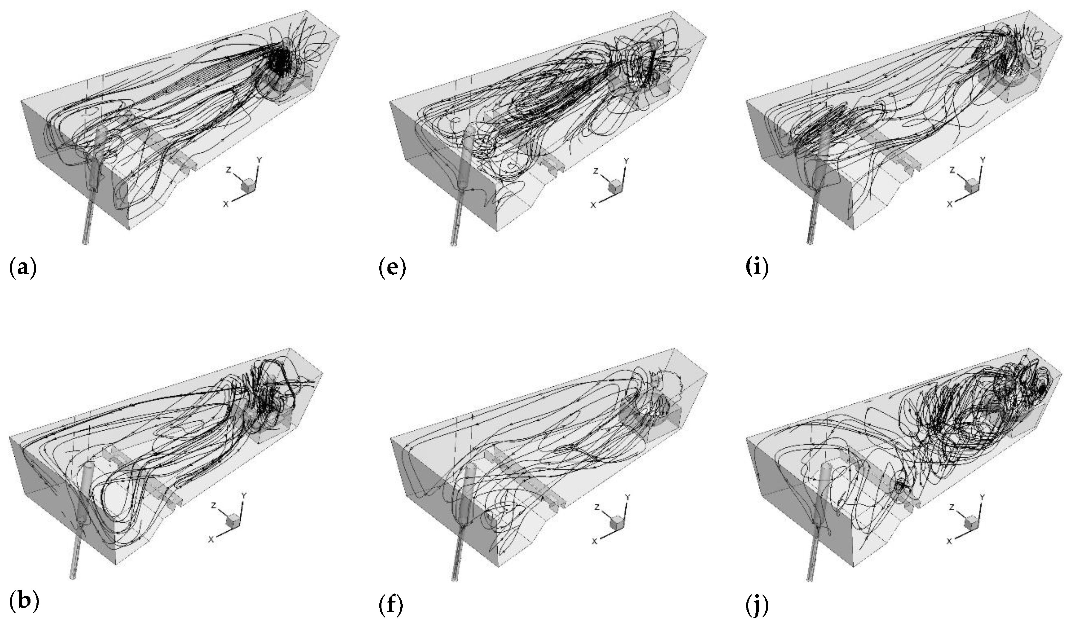
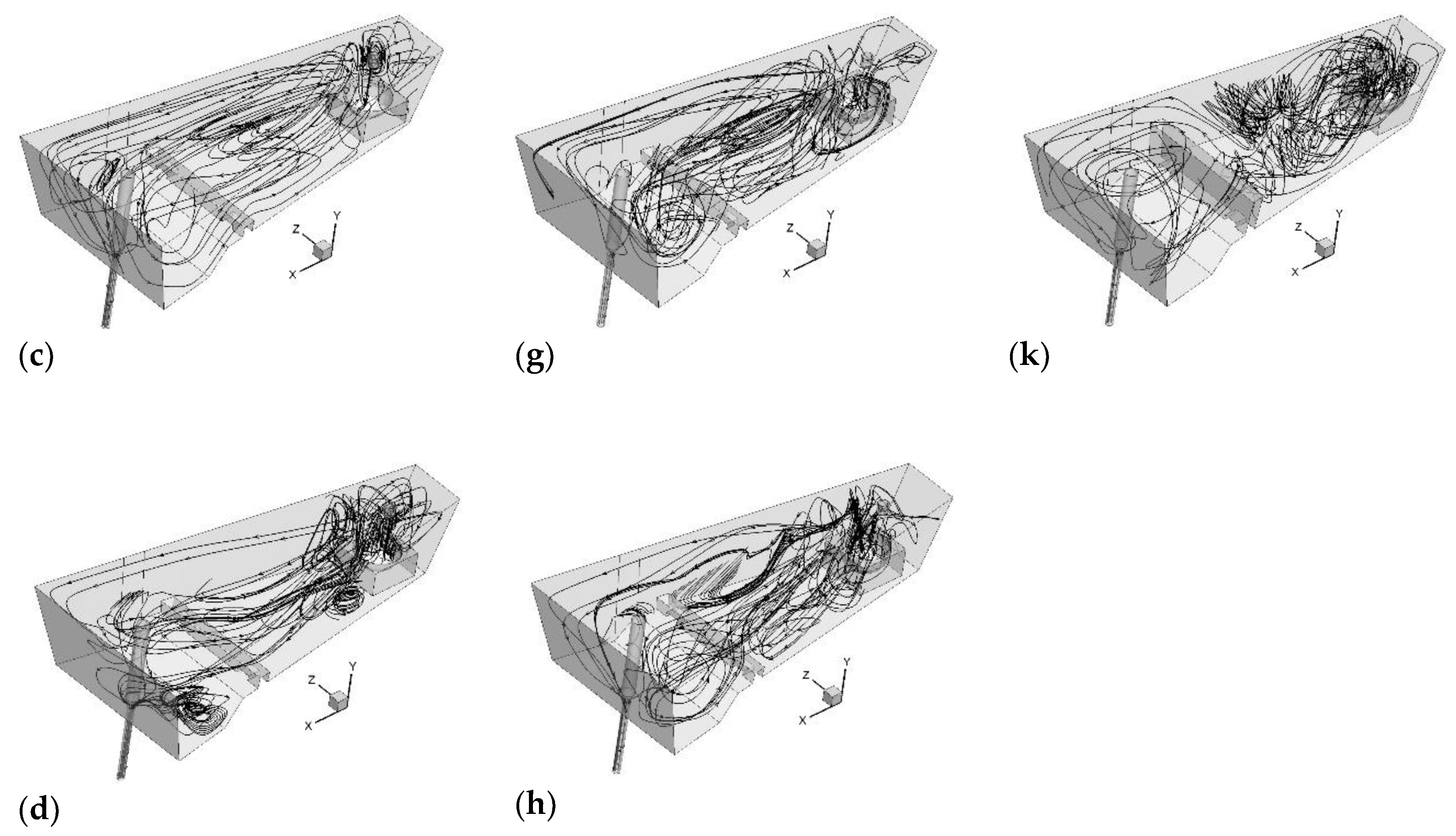
4.1. Influence of STC Position on Hydrodynamic Structure

Figure 2 shows the liquid steel paths in the tundish working space for steady state conditions. The tundish, as a flow reactor, is distinguished by the fact that any interference in its working space will result in a modification of the hydrodynamic conditions. In a tundish with standard-mounted STC and ladle shroud, liquid steel, after flowing into the STC, is reversed towards the free surface and then it flows on towards the nozzle and the stopper rod system (Figure 2a,c,f). For this reason, the pattern of liquid steel streams between the pouring zone and the stopper rod zone is horizontal. At the same time, reverse streams form at the tundish bottom, which then flow in the tundish pouring zone direction. Moving the STC by 0.075 m towards the stopper rod system zone results in the formation of additional horizontal and vertical liquid steel circulation zones in the region between the dam and the STC (Figure 2b,d,g). The chaotic motion of liquid steel in the central tundish part is intensified by a further displacement of the STC by 0.075 m towards the stopper rod system (Figure 2e,h). In the case of STC No. 3, we can also see a considerable asymmetry in the distribution of the streams with respect to the longitudinal tundish axis. The reverse stream is pushed to the central tundish part by lower streams flowing in from the STC side. Shifting the STC by 0.075 m towards the rear tundish wall does not significantly modify the hydrodynamic pattern being characteristic for a tundish with a standard-mounted STC (Figure 2i).
By contrast, its additional displacement by another 0.075 m towards the rear wall distinctly changes the pattern of flow in the tundish. Upon flowing into the STC, the liquid steel stream decomposes into two vertical circulation regions with respect to the longitudinal tundish axis (Figure 2j). This pattern changes in the dam installation location by the appearance of streams flowing to the nozzle, which are oriented primarily to the free surface and then descend towards the nozzle at the front tundish wall. A similar hydrodynamic pattern was also obtained in a tundish with a high dam (Figure 2k).
For the designed continuous casting variants with the modified tundish pouring zones, transient numerical simulations were performed, during which the change in marker concentration was recorded, whereby a residence time distribution curves. From the variation of marker concentration in time, the shares of stagnant volume flow, dispersed plug flow and well-mixed volume flow were calculated (Figure 3). The decrease in stagnant volume flow share and the increase in dispersed plug flow share both reduce the transient zone range. By contrast, minimizing the stagnant volume flow share and maximizing the well-mixed volume flow share will intensify the thermal and chemical homogenization of the liquid steel. Therefore, the ratio of dispersed plug flow to well mixed-volume flow should oscillate around the value of 0.5, because liquid steel homogeneity is important in the CSC process. It was found from the obtained results that moving the STC by 0.075 m towards the stopper rod system caused an increase in stagnant volume flow. Having said that, no increase in plug volume flow above 15% was obtained in the tundish equipment variants under examination. In the case of STC No. 3 and its shift towards the rear tundish wall by 0.15 m, a reduction in stagnant volume flow share by up to 27.4% was obtained. An additional increase in dam height with this non-standard STC position caused a further decrease in stagnant volume flow share by 5%, with an increase in well mixed volume flow up to a value of 61.3%.

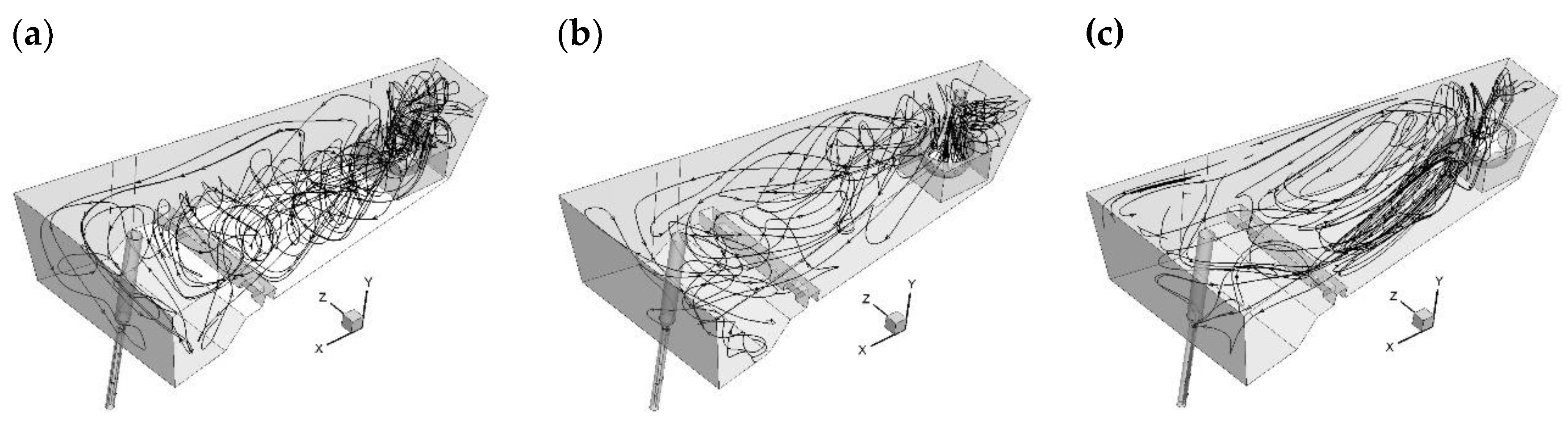
4.2. Influence of LS Position on Hydrodynamic Structure

Figure 4 shows the liquid steel paths in the tundish with different ladle shroud position for steady state conditions. Shifting the LS by 0.075 m towards the rear wall with the standard STC position does not significantly change the hydrodynamic pattern in the tundish working space (Figure 4a,c). By contrast, changing the LS position by another 0.75 m activates the vertical circulation of liquid steel (Figure 4b,d). In the stopper rod system zone, the vertical circulations located immediately at the free surface are observed. The steel flow in the tundish is markedly influenced by the LS position limited by the distance from the side wall. In these variants under discussion, there appears an asymmetric flow of liquid steel with a vertical recirculation pattern occurring on the tundish side, towards which the LS has been moved, and a horizontal recirculation pattern that exists on the opposite side with respect to the longitudinal axis (Figure 4e,f). The liquid steel motion pattern is further changed with the increase in STC pouring asymmetry and the displacement of the LS by another 0.075 m towards the side wall (Figure 4g,h). This time, the majority of liquid steel streams flow towards the nozzle in a horizontal pattern.
Analysis has shown that also a small change in LS position and asymmetric feeding stream penetration into the STC working region markedly modifies the hydrodynamic conditions (Figure 5). The analysis of the shares of individual flow types has demonstrated that change in LS position increases the stagnant volume flow share by over 30%. A dispersed plug flow share of below 15% will not balance out the adverse stagnant volume flow share. While a 100% increase in dispersed plug flow share was obtained in variants No. 18 and 19, the average stagnant volume flow share for these variants amounted to 29.4%. As for the obtained results changes in flow volume at a level of around 1–2% should be regarded as being within the range of numerical deviation, the level of stagnant volume flow comprises the 1/3 of the tundish working space.

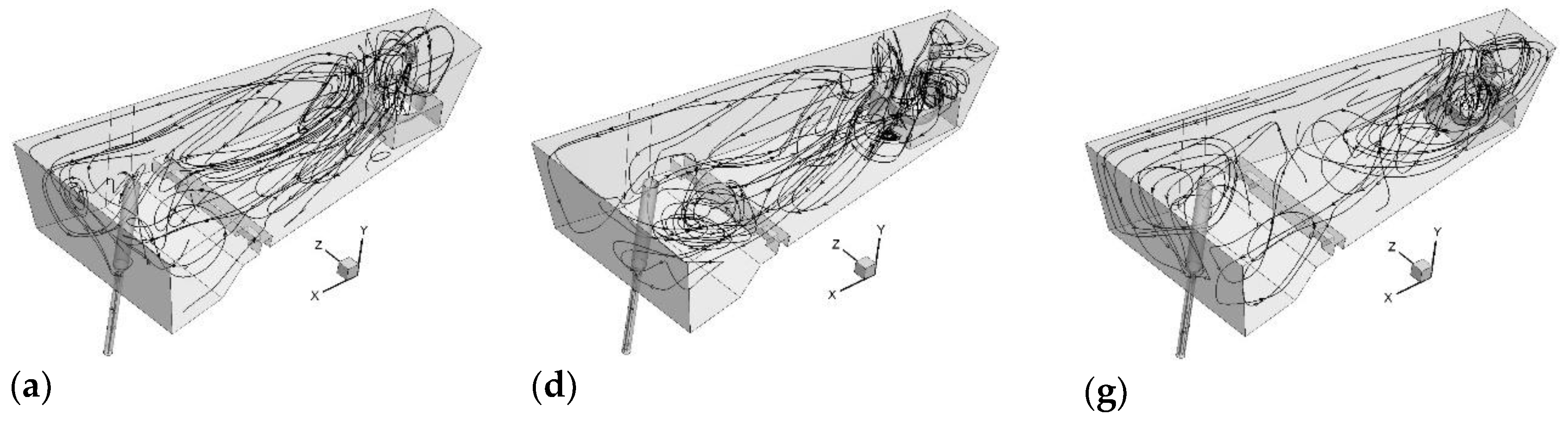
4.3. Influence of Both STC and LS Position on Hydrodynamic Structure

In variants No. 20 and 21, the STC and the LS were moved, respectively, by 0.075 m and 0.15 m from the base position towards the rear wall. In both cases, an asymmetric pattern with respect to the longitudinal tundish axis was obtained (Figure 6a,b). On the side opposite to the side on which the LS is situated, the steel motion has a horizontal behavior. By contrast, on the opposite side, a vertical circulation occurs. Whereas, the maximum possible displacement of the STC and the LS towards the side walls causes the formation of a hydrodynamic pattern similar to that occurring in the conditions of standard STC and LS positioning (Figure 6c). Streams of liquid steel flow in to the mould feed zone (tundish stopper rod zone) from the free surface side. Meanwhile, reverse streams form in the bottom region. As a result, there is a horizontal steel circulation in the zone between the dam and the STC. All results from Figure 6 are obtained for steady state conditions.
Variants No. 20 and 21 should be considered as emergency cases, especially as in both hydrodynamic systems the steel motion shows an over 30% share of stagnant volume flow and a small share of dispersed plug and well-mixed volume flows (Figure 7). To optimize the liquid steel motion in the rear portion of the tundish pouring zone, the STC and the LS were moved towards the rear tundish wall. However, this operation did not bring about any significant changes in the hydrodynamic pattern, as shown by the obtained stagnant volume, dispersed plug and well-mixed volume flow shares (Figure 7).

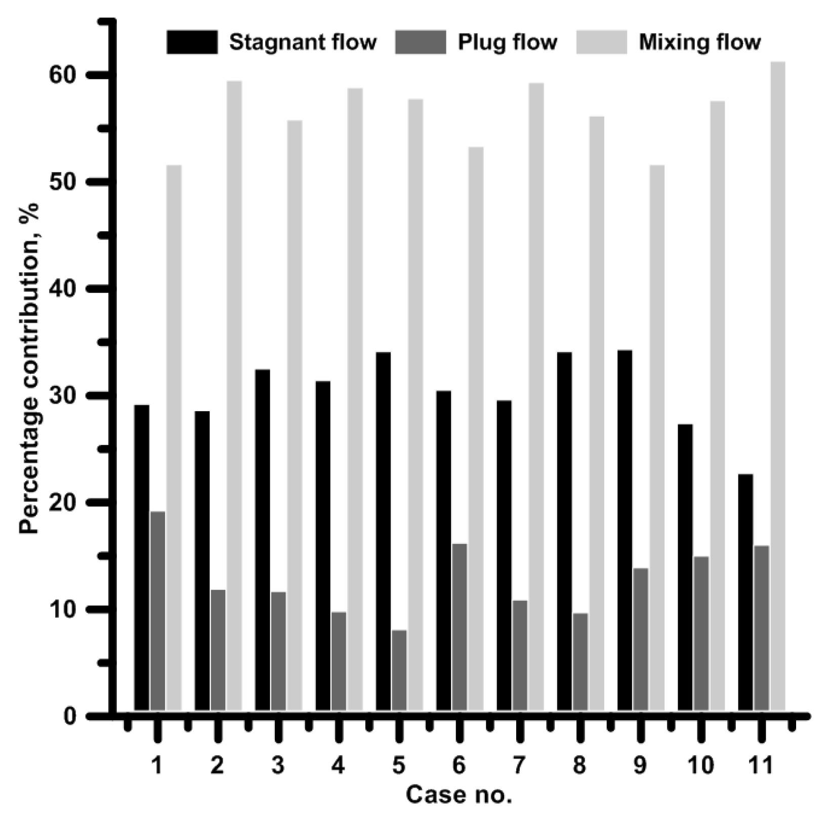
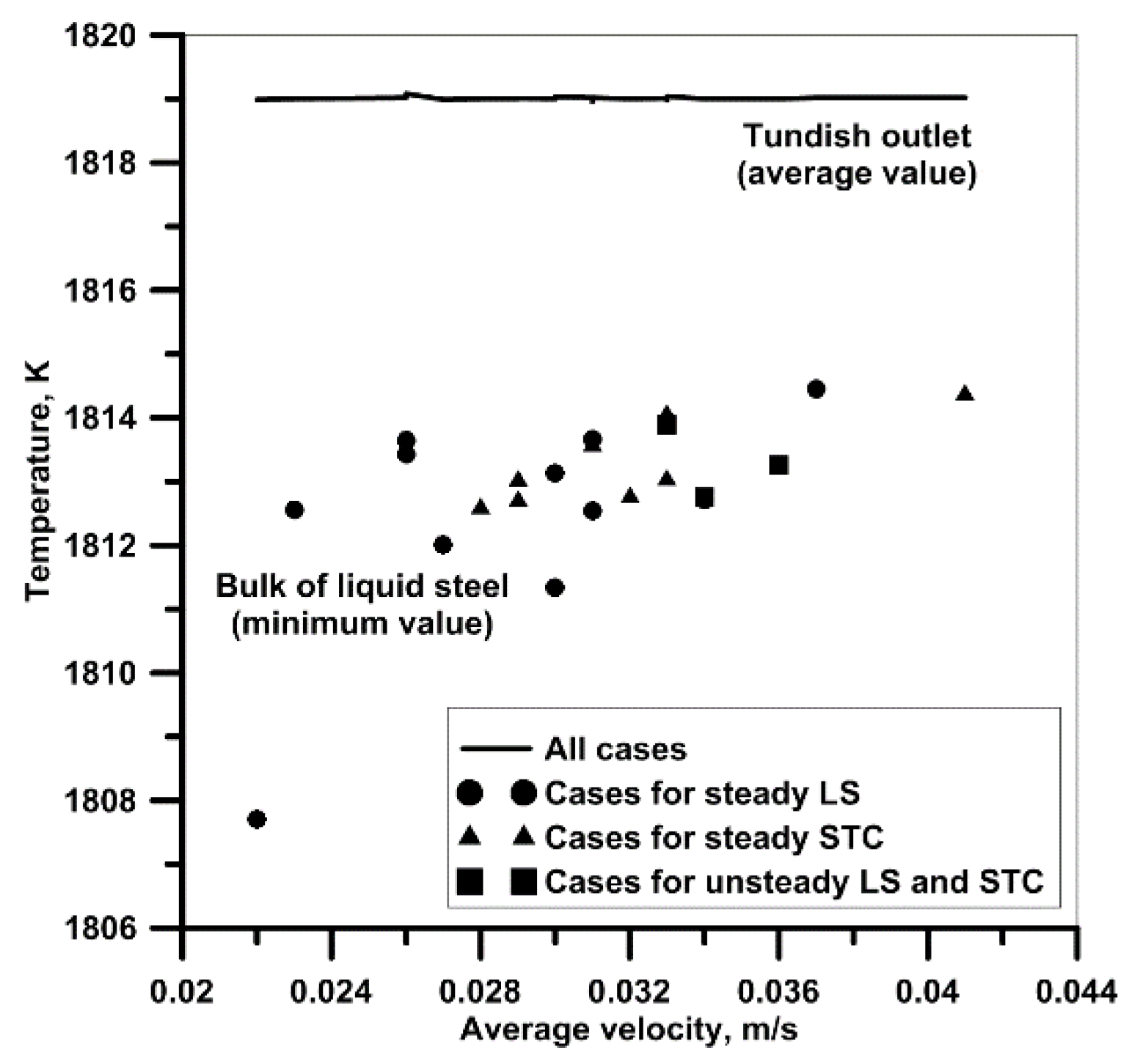
4.4. Influence STC and LS Position on Liquid Steel Temperature, Velocity, and Mixing

STCs installed in the tundish working space influence not only on the steel flow directions, but also on the value of steel velocity or temperature. Figure 8 shows the average values of temperature at the nozzle and the minimum values of temperature in the liquid steel volume. It has been demonstrated that the change in the position of the STC or LS in the examined range does not affect the temperature of steel flowing into the mould. Whereas there is a noticeable effect of the relative STC and LS position on the minimum value of temperature in the tundish working space. The interaction of the feeding stream with the STC definitely influences also the average velocity of liquid steel in the tundish working space. The proposed STCs without the conventional flange can effectively reduce the liquid steel flow velocity, which for a tundish with no STC is 0.036 m/s [38,39]. The slower the tundish steel flow, the lower the liquid steel temperature value was found in the tundish working space. In some places, this may cause the formation of cold zones of a temperature close to the solidus temperature of the steel grade being cast. This is all the more so because during the actual CSC process, the liquid steel temperature steadily goes down as the steel flows out from the ladle to the tundish.
In order to verify the potential effect of hydrodynamic conditions prevailing in the tundish on the steel motion at the submerged entry nozzle, a measuring line located in its axis was generated. Figure 9 illustrates the liquid steel velocity in the submerged entry nozzle axis for steady state conditions. The results shown apply to tundish variants with an average steel flow velocity in the range from 0.022 to 0.041 m/s. It can be seen that neither the changes in flow direction, nor the changes in average liquid steel velocity value have any significant influence on the velocity of steel flow at the submerged entry nozzle. In the upper part of the submerged entry nozzle, the highest steel flow velocity values occur, which are greater than those in the tundish working space by a factor of 40. For this reason, the upper submerged entry nozzle part is especially exposed to the erosive action of liquid steel.
Another parameter that is important from the point of view of the CSC process is the transient zone range (Figure 10). The transient zone can be influenced either by substantially reducing the stagnant volume flow share, or by increasing the share of dispersed plug flow. Results from Figure 10 were calculated from step input F-curve obtained during transient numerical simulations. Therefore, in the tundish variant with a high dam and a shifted STC, which is optimal in terms of hydrodynamic pattern, a reduction in transient zone range by 2 tons was obtained. While the decrease in dispersed plug flow share to the benefit of well mixed volume flow with a similar share of stagnant volume flow caused an increase in transient zone range by over 1.5 tons.

5. Conclusions

Based on the computer simulations carried out, it has been found that:
It is possible to reduce the stagnant volume flow share in the hydrodynamic pattern by changing the position of the STC relative to the LS.
Change in the position of the LS in relation to the STC clearly impairs the hydrodynamic conditions in the tundish under examination.
Change in relative STC and LS position does not influence the temperature of steel flowing into the mould, thought it does have an effect on local temperature drops in the tundish working space.
The proposed STCs with no working flange can effectively reduce the velocity of steel flow in the tundish, while offering greater flexibility in their mounting when preparing the tundish for the casting sequence.
The activation of the tundish working region by setting the STC asymmetrically with respect to the feeding stream and increasing the dam height reduces the transient zone range.

Funding

This research was funded by Ministry of Science and Higher Education, grant number BS 204-301/2005/P.

Acknowledgments

The research work has been financed from the Ministry of Science and Higher Education Republic of Poland as Statutory Researches.

Conflicts of Interest

Author declare no conflicts of interest.

References

  1. Bebber, H.; Kranz, A. A plasma tundish heater. Steel Res. Int. 2001, 72, 460–465. [Google Scholar] [CrossRef]
  2. Stolte, G. Secondary Metallurgy; Verlag Stahleisen GmbH: Dusseldorf, Germany, 2008; ISBN 3-514-00648-2. [Google Scholar]
  3. Madias, J.; Martin, D.; Ferreyra, M.; Villoria, R.; Garamendy, A. Design and Plant Experience Using an Advanced Pouring Box to Receive and distribute the Steel in a Six Strand Tundish. ISIJ Int. 1999, 39, 787–794. [Google Scholar] [CrossRef]
  4. Pardeshi, R.; Basak, S.; Singh, A.K.; Basu, B.; Mahashadbe, V.; Roy, S.K.; Kumar, S. Mathematical Modeling of the tundish of a Single-Strand Slab Caster. ISIJ Int. 2004, 44, 1534–1540. [Google Scholar] [CrossRef]
  5. Falkus, J.; Lamut, J. Model testing of the bath flow through the tundish of continuous casting machine. Arch. Metall. Mater. 2005, 50, 709–718. [Google Scholar]
  6. Wang, J.; Zhu, M.Y.; Zhou, H.B.; Wang, Y. Fluid Flow and Interfacial Phenomenon of Slag and Metal in Continuous Casting Tundish with Argon Blowing. J. Iron Steel Res. Int. 2008, 15, 26–31. [Google Scholar] [CrossRef]
  7. Cwudziński, A. Numerical simulation of steel flow through a one strand slab tundish with steel flow control devices. Can. Metall. Q. 2010, 49, 63–72. [Google Scholar] [CrossRef]
  8. Cwudziński, A.; Jowsa, J. Numerical analysis of liquid steel flow structure in the one strand slab tundish with subflux turbulence controller and dam. Arch. Metall. Mater. 2012, 57, 297–301. [Google Scholar] [CrossRef]
  9. Pieprzyca, J.; Merder, T.; Saternus, M.; Kania, H. The change of liquid steel flow control system in the tundish—Modelling research. Arch. Metall. Mater. 2014, 59, 1433–1440. [Google Scholar] [CrossRef]
  10. Chen, D.; Xie, X.; Long, M.; Zhang, M.; Zhang, L. Hydraulics and Mathematics Simulation on the Wier and Gas Curtain in tundish of Ultrathick Slab Continuous Casting. Metall. Mater. Trans. B 2014, 45, 392–398. [Google Scholar] [CrossRef]
  11. Cloete, J.H.; Akdogan, G.; Bradshaw, S.M.; Chibwe, D.K. Physical and numerical modelling of a four-strand steelmaking tundish using flow analysis of different configurations. J. S. Afr. Inst. Min. Metall. 2015, 115, 355–362. [Google Scholar] [CrossRef] [Green Version]
  12. Chen, C.; Ni, P.; Jonsson, L.T.I.; Tilliander, A.; Cheng, G.; Jönsson, P.G. A model Study of inclusions Deposition, Macroscopic Transport, and Dynamic Removal at Steel-Slag Interface for Different Tundish Designs. Metall. Mater. Trans. B 2016, 47, 1916–1932. [Google Scholar] [CrossRef]
  13. Huang, J.; Zhang, Y.; Zhang, Y.; Zhang, Y.; Ye, X.; Wang, B. Study of Flow Characteristics of Tundish Based on Digital Image Velocimetry Technique. Metall. Mater. Trans. B 2016, 47, 3144–3157. [Google Scholar] [CrossRef]
  14. Tang, H.; Guo, L.; Wu, G.; Xiao, H.; Yao, H.; Zhang, J. Hydrodynamic Modeling and Mathematical Simulation on Flow Field and Inclusion Removal in a Seven-Strand Continuous Casting Tundish with Channel Type Induction Heating. Metals 2018, 8, 374. [Google Scholar] [CrossRef]
  15. Hou, Q.; Yue, Q.; Wang, H.; Zou, Z.; Yu, A. Modeling of inclusion Motion and Flow Patterns in Swirling Flow Tundishes with Symmetrical and Asymmetrical Structures. ISIJ Int. 2008, 48, 787–792. [Google Scholar] [CrossRef]
  16. Bulkowski, L.; Galisz, U.; Kania, H.; Kudliński, Z.; Pieprzyca, J.; Barański, J. Industrial tests of steel filtering process. Arch. Metall. Mater. 2012, 57, 363–369. [Google Scholar] [CrossRef]
  17. Wang, Y.; Zhong, Y.; Wang, B.; Lei, Z.; Ren, W.; Ren, Z. Numerical and Experimental Analysis of Flow Phenomenon in Centrifugal Flow Tundish. ISIJ Int. 2009, 49, 1542–1550. [Google Scholar] [CrossRef] [Green Version]
  18. Tripathi, A. Mathematical modelling of flow control in a tundish using electro-magnetic forces. Appl. Math. Model. 2011, 35, 5075–5090. [Google Scholar] [CrossRef]
  19. Tripathi, A. Numerical Investigation of Electro-magnetic Flow Control Phenomenon in a Tundish. ISIJ Int. 2012, 52, 447–456. [Google Scholar] [CrossRef] [Green Version]
  20. Aquilar-Corona, A.; Morales, R.D.; Diaz-Cruz, M.; Palafox-Ramos, J.; Rozdriguez-Hernandez, H. Modelling the effects o off-centered ladle streams on fluid flow of liquid steel in a slab tundish. Steel Res. Int. 2002, 73, 438–444. [Google Scholar] [CrossRef]
  21. Chattopadhyay, K.; Isac, M.; Guthrie, R.I.L. Physical and Mathematical Modelling to Study the Effect of Ladle Shroud Mis-alignment on Liquid Metal Quality in a Tundish. ISIJ Int. 2011, 51, 759–768. [Google Scholar] [CrossRef] [Green Version]
  22. Chattopadhyay, K.; Liu, F.G.; Isac, M.; Guthrie, R.I.L. Effect of vertical alignment of ladle shroud on transient steel quality output from multistrand tundish. Ironmak. Steelmak. 2011, 38, 112–118. [Google Scholar] [CrossRef]
  23. Cwudziński, A. Numerical Simulation of Liquid Steel Flow in Wedge-type One-strand Slab tundish with a Subflux Turbulence Controller and an Argon Injection System. Steel Res. Int. 2010, 81, 123–444. [Google Scholar] [CrossRef]
  24. Cwudziński, A. Numerical and Physical Modeling of Liquid steel Active Flow in tundish with Subflux Turbulence Controller and Dam. Steel Res. Int. 2014, 85, 902–917. [Google Scholar] [CrossRef]
  25. Cwudziński, A. Numerical, Physical and Industrial Studies of Liquid Steel Chemical Homogenisation in One strand Tundish with Subflux Turbulence Controller. Steel Res. Int. 2015, 86, 972–983. [Google Scholar] [CrossRef]
  26. Szekely, J. Fluid Flow Phenomena in Metals Processing; Academic Press Inc.: New York, NY, USA, 1979; ISBN 0-12-680840-6. [Google Scholar]
  27. Mazumdar, D.; Evans, J.W. Modeling of Steelmaking Processes; CRC Press: Boca Raton, FL, USA, 2010; ISBN 978-1-4200-6243-4. [Google Scholar]
  28. Chakraborty, S.; Sahai, Y. Effect of holding time and surface cover in ladles on liquid steel flow in continuous casting tundishes. Metall. Mater. Trans. B 1992, 23, 153–167. [Google Scholar] [CrossRef]
  29. Morales, R.D.; Lopez-Ramirez, S.; Palafox-Ramos, J.; Zacharias, D. Numerical and modeling analysis of fluid flow and heat transfer of liquid steel in a tundish with different flow control devices. ISIJ Int. 1999, 39, 455–462. [Google Scholar] [CrossRef]
  30. Miki, Y.; Thomas, B.G. Modeling of inclusion removal in a tundish. Metall. Mater. Trans. B 1999, 30, 639–654. [Google Scholar] [CrossRef] [Green Version]
  31. Barron-Meza, M.A.; de Barreto-Sandoval, J.J.; Morales, R.D. Physical and mathematical models of steel flow and heat transfer in a tundish heated by plasma. Metall. Mater. Trans. B 2000, 31, 63–74. [Google Scholar] [CrossRef]
  32. Lopez-Ramirez, S.; de Barreto, J.J.; Palafox-Ramos, J.; Morales, R.D.; Zacharias, D. Modeling study of the influence of turbulence inhibitors on the molten steel flow, tracer dispersion, and inclusion trajectories in tundish. Metall. Mater. Trans. B 2001, 32, 615–627. [Google Scholar] [CrossRef]
  33. Morales, R.D.; Lopez-Ramirez, S.; Palafox-Ramos, J.; Zacharias, D. Mathematical simulation of effects of flow control devices and buoyancy forces on molten steel flow and evolution of output temperatures in tundish. Ironmak. Steelmak. 2001, 28, 33–43. [Google Scholar] [CrossRef]
  34. Singh, R.K.; Paul, A.; Ray, K. Modelling of flow behaviour in continuous casting tundish. Scand. J. Metall. 2003, 32, 137–146. [Google Scholar] [CrossRef]
  35. Lopez-Ramirez, S.; de Barreto, J.J.; Vite-Martinez, P.; Romero Serrano, J.A.; Duran-Valencia, C. Physical and mathematical determination of the influence of input temperature changes on the molten steel flow characteristics in slab tundishes. Metall. Mater. Trans. B 2004, 35, 957–966. [Google Scholar] [CrossRef]
  36. Zhang, L. Fluid flow, heat transfer and inclusion motion in a four-strand billet continuous casting tundish. Steel Res. Int. 2005, 76, 784–796. [Google Scholar] [CrossRef]
  37. Cwudziński, A. Numerical and physical prediction of hydrodynamic conditions in one strand slab tundish. Metall. Res. Technol. 2014, 111, 45–55. [Google Scholar] [CrossRef]
  38. Cwudziński, A. Physical and mathematical simulation of liquid steel mixing zone in one strand continuous casting tundish. Int. J. Cast Metals Res. 2017, 30, 50–60. [Google Scholar] [CrossRef]
  39. Cwudziński, A. Mathematical simulation and water modelling of liquid steel interaction with an argon bubble curtain in a one strand continuous casting tundish. J. S. Afr. Inst. Min. Metall. 2018, 118, 545–554. [Google Scholar] [CrossRef]
  40. Sahai, Y.; Toshihiko, E. Tundish Technology for Clean Steel Production; World Scientific: Singapore, 2008; ISBN-13 978-981-270-621-8. [Google Scholar]
  41. Sahai, Y.; Emi, T. Melt flow characterization in continuous casting tundishes. ISIJ Int. 1996, 36, 667–672. [Google Scholar] [CrossRef]
  42. Mazumdar, D.; Guthrie, R.I.L. The physical and mathematical modelling of continuous casting tundish systems. ISIJ Int. 1999, 39, 524–547. [Google Scholar] [CrossRef]
  43. Thomas, B.G. Modeling study of intermixing in tundish and strand during a continuous casting grade transition. In The Continuous Casting—Tundish Operations; Schade, J., Ed.; Iron & Steel Society: Warrendale, PA, USA, 2003; Volume 10, pp. 115–127. ISBN 1-886362-70-X. [Google Scholar]
  44. Cwudziński, A. Regulation of Steel Flow in the Slab Tundish. Ph.D. Thesis, Czestochowa University of Technology, Częstochowa, Poland, 2008. (In Polish). [Google Scholar]
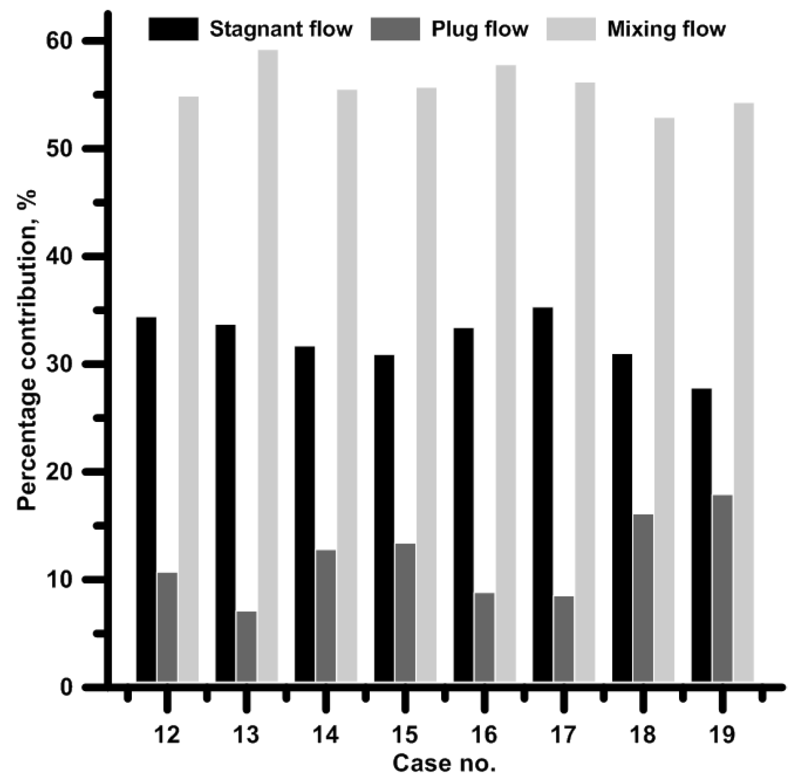
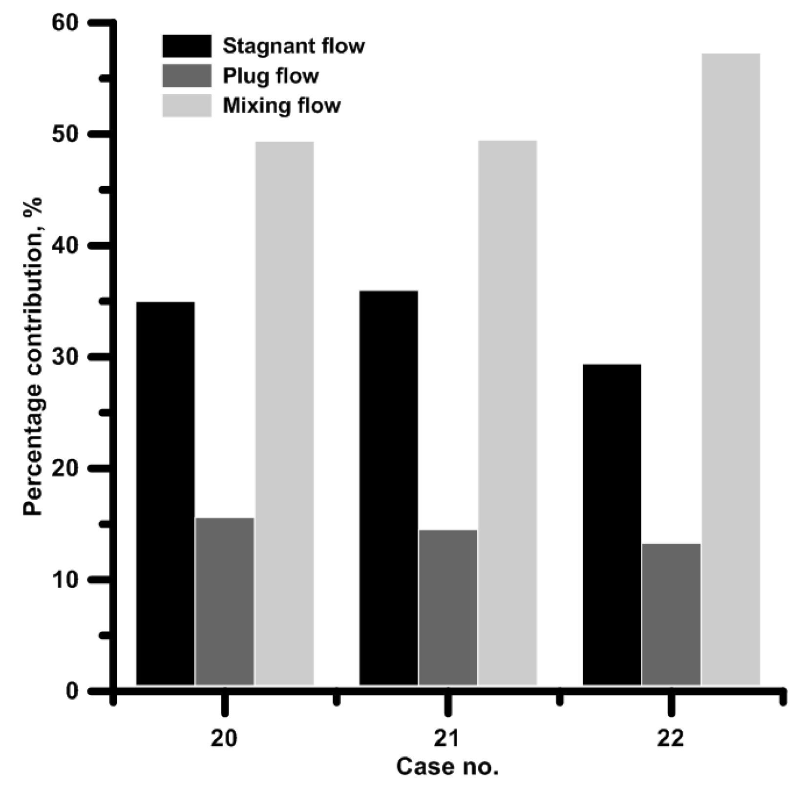
Figure 1. One strand slab tundish: (a) standard position of subflux turbulence controller (STC) No. 1, (b) standard position of STC No. 2, (c) standard position of STC No. 3, (d) case with high dam and proposed position of STC No. 3.
Metals 09 00068 g001
Figure 2. Liquid steel paths in the internal working volume of tundish for steady position of ladle shroud: (a) case No. 1, (b) case No. 2, (c) case No. 3, (d) case No. 4, (e) case No. 5, (f) case No. 6, (g) case No. 7, (h) case No. 8, (i) case No. 9, (j) case No. 10, and (k) case No. 11.
Metals 09 00068 g002aMetals 09 00068 g002b
Figure 3. Hydrodynamic conditions for considered tundish variants with steady position of ladle shroud.
Metals 09 00068 g003
Figure 4. Liquid steel paths in the internal working volume of tundish for steady position of subflux turbulence controller: (a) case No. 12, (b) case No. 13, (c) case No. 14, (d) case No. 15, (e) case No. 16, (f) case No. 17, (g) case No. 18, and (h) case No. 19.
Metals 09 00068 g004aMetals 09 00068 g004b
Figure 5. Hydrodynamic conditions for considered tundish variants with steady position of subflux turbulence controller.
Metals 09 00068 g005
Figure 6. Liquid steel paths in the internal working volume of tundish for unsteady position of subflux turbulence controller and ladle shroud: (a) case No. 20, (b) case No. 21, and (c) case No. 22.
Metals 09 00068 g006
Figure 7. Hydrodynamic conditions for considered tundish variants with unsteady position of subflux turbulence controller and ladle shroud
Metals 09 00068 g007
Figure 8. Liquid steel temperature for all considered tundish variants and steady state conditions.
Metals 09 00068 g008
Figure 9. Liquid steel velocity magnitude in the submerged entry nozzle for selected hydrodynamic conditions
Metals 09 00068 g009
Figure 10. Transition zone for selected tundish variants.
Metals 09 00068 g010
Table 1. Considered variants of STC and ladle shroud (LS) mutual positions in the tundish pouring zone.
Case No.STC No.Dam Height (mm)Distance from Base Position (mm) and Direction of STC ShiftingDistance from Base Position (mm) and Direction of LS Shifting
075 F150 F75 B150 B75 L75 R075 B150 B300 B75 L75 R150 L150 R
11120×------×-------
21120-×-----×-------
32120×------×-------
42120-×-----×-------
52120--×----×-------
63120×------×-------
73120-×-----×-------
83120--×----×-------
93120---×---×-------
103120----×--×-------
113400----×--×-------
122120×-------×------
132120×--------×-----
143120×-------×------
153120×--------×-----
163120×----------×---
173120×-----------×--
183120×------------×-
193120×-------------×
203120-----×---×-----
213120------×--×-----
223120----×-----×----

