Article

Effect of Surface Roughness on the Bonding Strength and Spring-Back of a CFRP/CR980 Hybrid Composite

1
Precision Manufacturing System Division, Graduate School, Pusan National University, San 30 Chang Jun-dong, Geum Jung-Gu, Busan 46241, Korea
2
School of Mechanical Engineering, Kyungnam University, 7 Kyungnamdaehak-ro, Masanhappo-gu, Changwon-si 51767, Korea
3
School of Mechanical Engineering, Pusan National University, San 30 Chang Jun-dong, Geum Jung-Gu, Busan 46241, Korea
*
Author to whom correspondence should be addressed.
Metals 2018, 8(9), 716; https://doi.org/10.3390/met8090716
Submission received: 12 July 2018 / Revised: 2 September 2018 / Accepted: 10 September 2018 / Published: 12 September 2018
(This article belongs to the Special Issue Material and Process Design for Lightweight Structures)

Abstract

:
Carbon fiber-reinforced plastic (CFRP), which is a light and composite material, has a higher specific strength and stiffness than metal materials. However, owing to its low elongation, it is vulnerable to local impacts such as collision. Therefore, hybrid composite materials that can overcome the disadvantages of homogeneous materials by bonding CFRP and metal materials are increasingly popular. In this study, a physical surface treatment sandblast process was applied on a high tensile steel plate (CR980) manufactured by cold rolling to form another surface condition, and the bonding strength with CFRP was measured. In addition, spring-back due to the manufacturing process of the CFRP and CR980 hybrid composite material bonded with different surface roughness was observed. The bonding strength and the spring-back angle of the CFRP/CR980 hybrid composite material tended to increase with the increase in the surface roughness.

1. Introduction

In the case of eco-friendly automobiles, additional components like batteries and motors are added for the development of new power sources, which has lead inevitably to an increase in the vehicle weight. On the basis of the European 2020 target, the use of non-ferrous metals and synthetic resins in eco-friendly vehicles will each increase by more than 10% [1].
Recently, the demand for the comfort and safety of automobiles, such as body reinforcements, airbags, automobile electric motors, and accumulators, has increased, and the weight of the vehicle is showing an increasing trend. Therefore, the problem of automobile weight should be addressed [2].
In general, the performance improvement of automobile by a 10% reduction in the weight of the automobile body contributes a 6–8% improvement in fuel efficiency, 8% improvement in acceleration and braking performance, 6% improvement in steering performance, 4.5% reduction in CO, 4.5% reduction in HC, and 8.8% reduction in NOx.
Recently, aluminum alloys, magnesium alloys, titanium alloys, advanced high strength steel (AHSS), and composite materials are increasingly being used in the automobile industry. Many studies have investigated the use of carbon fiber-reinforced plastic (CFRP), which is a composite material, owing to its higher specific strength and stiffness than steel material [3,4,5]. In addition, studies have been carried out on the tensile failure mechanism of CFRP prepreg (pre-impregnated composite fibers) [6] and comparison of the tensile strengths of the different epoxy composite materials of CFRP [7]. Prepreg is a material in which matrix epoxy resin is impregnated in the carbon fiber, which is an intermediate material of CFRP as well as a reinforcement material. CFRP is used in a variety of fields, such as aircraft, leisure goods, and automobiles, owing to its lightweight properties. However, despite its high tensile strength, CFRP is vulnerable to local impacts like collisions, owing to its low elongation (approximately 2%). In recent years, there has been increased research interest on hybrid composites that overcome the limitations of materials, by bonding CFRP and metal materials to address the problems of such a heterogeneous material. Studies on interfacial bonding between CFRP and steel [8] and studies on epoxy flow in deep drawing processes in CR340 and CFRP composites have been carried out [9,10].
As early as 1879, Thomas Edison discovered that one could bake cotton and bamboo bioderived materials at high temperatures, resulting in carbonization into a carbon fiber filament. This was used in the first lightbulb of an incandescent nature that is powered by electricity [11]. As such, materials from nature should be considered when understanding the spring-back response, due to the viscoelastic nature of the cellulose polymer embedded around a sheath of protective lignin and bonded hemicellulose for stress transfer [12,13]. The significant response in wood-based composites is a classic example of differential swell in different components of natural materials that results in delamination [14]. As such, it is anticipated that carbon fibers may be subject to spring-back, due to the specific elasticity of a polymer originally designed by nature.
In the case of CFRP and metal hybrid composites, studies on spring-back are lacking. Therefore, research on spring-back after forming CFRP and metal hybrid composite material is necessary. In this research, changes in spring-back according to changes in the production process was investigated through a primary experiment, such as V-being before manufacturing the parts with complicated shapes (like automobile parts) considering the lamination sequence of the CFRP, the number of lamination prepreg, and lamination direction.
CR980 material utilized as automobile material as used in this study is excellent in terms of not only its economic feasibility and light weight, but also its high strength compared with alternative materials, such as aluminum. In particular, CR980 has an excellent process capability, such that products having very complicated shapes can be produced compared with using aluminum. With the application of the hot press forming process followed by the expansion of high-strength steel, the need for new process technology to solve process factors with a low feasibility is increasing due to an increase in the mold processing cost, installation cost of development equipment, and cycle time. The steel used in this study was a high tensile steel plate (CR980) manufactured by cold rolling. CR980 material is a recently developed advanced high strength steel, which is widely used as a pillar part and the underframe of a car body, which plays very important roles by absorbing impacts during collision of cars. A lap shear test was carried out using a hybrid material mechanically bonded according to variations in the degree of surface treatment during bonding of the two materials, CFRP and CR980, with the process parameters of surface roughness, compressive force, and compression direction. Spring-back measurements for the specimen having V-bending according to the radius of the punch and die was also carried out.
In the case of a hybrid composite material, the reinforcement material and matrix may not be well bonded. In this case, delamination occurs, which impairs the absorption capability. To improve the bonding strength of these heterogeneous materials, physical surface treatment was carried out using the sandblast method, which is a physical surface treatment, and the degree of surface roughness was measured by the Rz value of a 10-point average roughness. Experiments were conducted to investigate the change in the bond strength according to the degree of surface roughness and variation in the bonding pressure.

2. Experiments

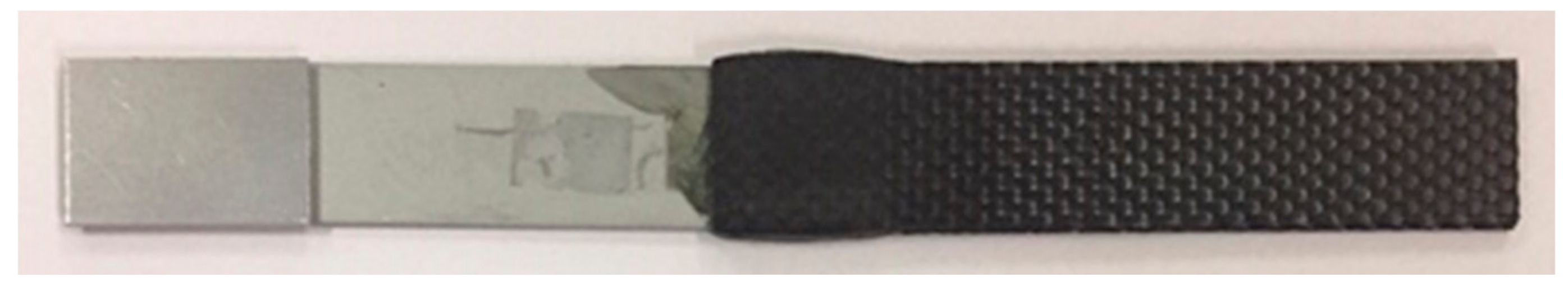
2.1. Shear Lap Adhesion Test of the CFRP/CR980 Hybrid Composite

2.1.1. Preparation of Specimen

Figure 1 shows a schematic diagram of the equipment for fabricating CFRP using 10 prepregs.
An optimum condition to fabricate a CFRP involved compressing ten sheets of prepreg at 140 °C at a pressure of 0.5 MPa. The curing of the epoxy was performed for 30 min [15]. The CFRP used in the experiment was a plain carbon fiber from TORAY. The thickness of the prepreg was 0.27 mm, and the thermosetting prepreg had an initial epoxy weight percentage of 42 wt %. CR980 steel is a material that is applied to automobile pillars and underframes, which generally protects the driver from external impact. The thickness of the CR980 material used was 1.2 mm. For 0 degrees of rolling direction, the tensile strength and elongation were 900 MPa and 18.8%, respectively. For 90 degrees of rolling direction, the tensile strength and elongation were 1053 MPa and 18.0%, respectively. Values of normal anisotropic (R) for 0 and 90 degrees are 0.57 and 0.65, respectively. Details of the material are presented in Table 1 and Table 2.

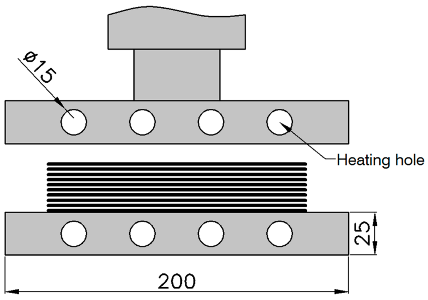
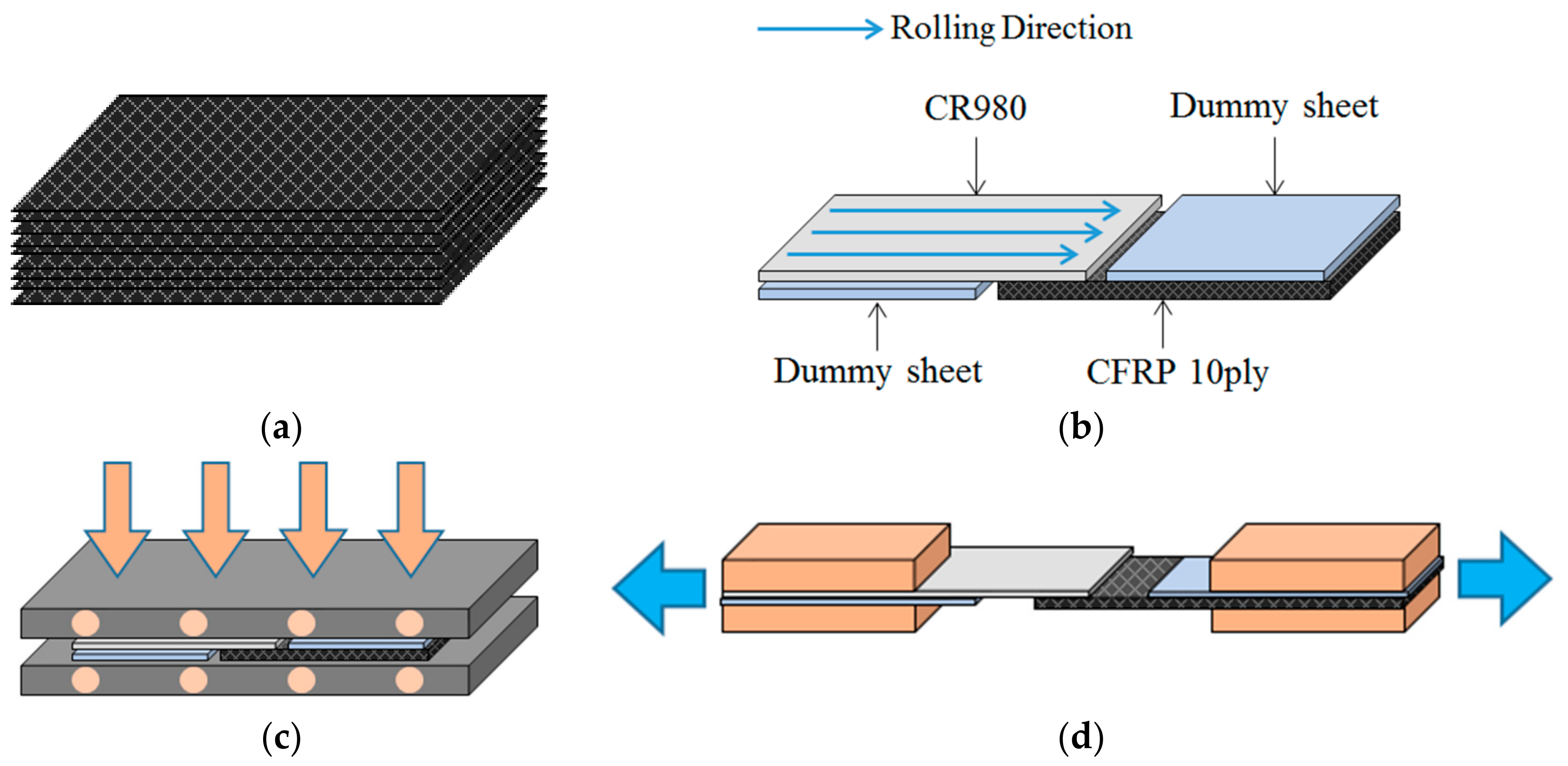
2.1.2. Production of Specimen

A lap shear adhesion test was conducted to measure the bonding strength. The test specimen production method is shown in Figure 2. Hot compression molding process was used to produce test specimens for bonding strength measurement. Table 3 lists the parameters of the hot compression molding process.
Sandblast surface treatment was carried out on the surface of one side. Sandblasting is a process to give the surface of CR980 a physically rough surface by spraying sand with compressed air. The degree of roughness is categorized according to the particle size of the sand. Unnecessary deposits are removed using sandblast, and the surface of the CR980 becomes a fine uneven surface, making the epoxy more permeable, in order to measure the difference in the bonding strength. Ten CFRP specimens were produced by laminating CR980 materials, each having a surface roughness of Rz = 20 μm, 35 μm, 45 μm, and 60 μm, respectively. The sizes of the specimens were 100 × 25 mm. The bonding area of the two materials was set to 20 × 25 mm at the center, and pressed and heated at 160 °C at 1 MPa and 2 MPa of pressure, respectively, followed by curing for 30 min. For precise temperature control, the room temperature was kept constant and the temperature of each mold was measured and controlled using a heat controller and heat cartridge. The equipment used in the experiment was a 25-ton Material Testing System (MTS). For this bonding strength measurement experiment, an appropriate manufacturing method was used by referring to the KS M 3713: 2012 standard [19]. The overall test method of the CFRP is also presented in ASTM D4762-16 [20].
Figure 3 show photographs of the preparation of the test specimen using the above method. Figure 4 show photographs of CR980 material that has been surface treated with sandblast, whose surface roughness was measured using an optical roughness tester. Figure 4a shows the specimen of surface treatment condition of Rz = 20 μm, Figure 4b shows the surface treatment condition of Rz = 35 μm, Figure 4c shows a photograph of the specimen with the surface treatment condition Rz = 45 μm, and Figure 4d shows photographs of surface roughness with the treatment condition Rz = 60 μm.
The shear lap adhesion test for the bonding strength was carried out by setting the shear rate to 2 mm/min. The steel tab was attached to the grip to prevent the grip of the specimen from being damaged by the bite of the machine.

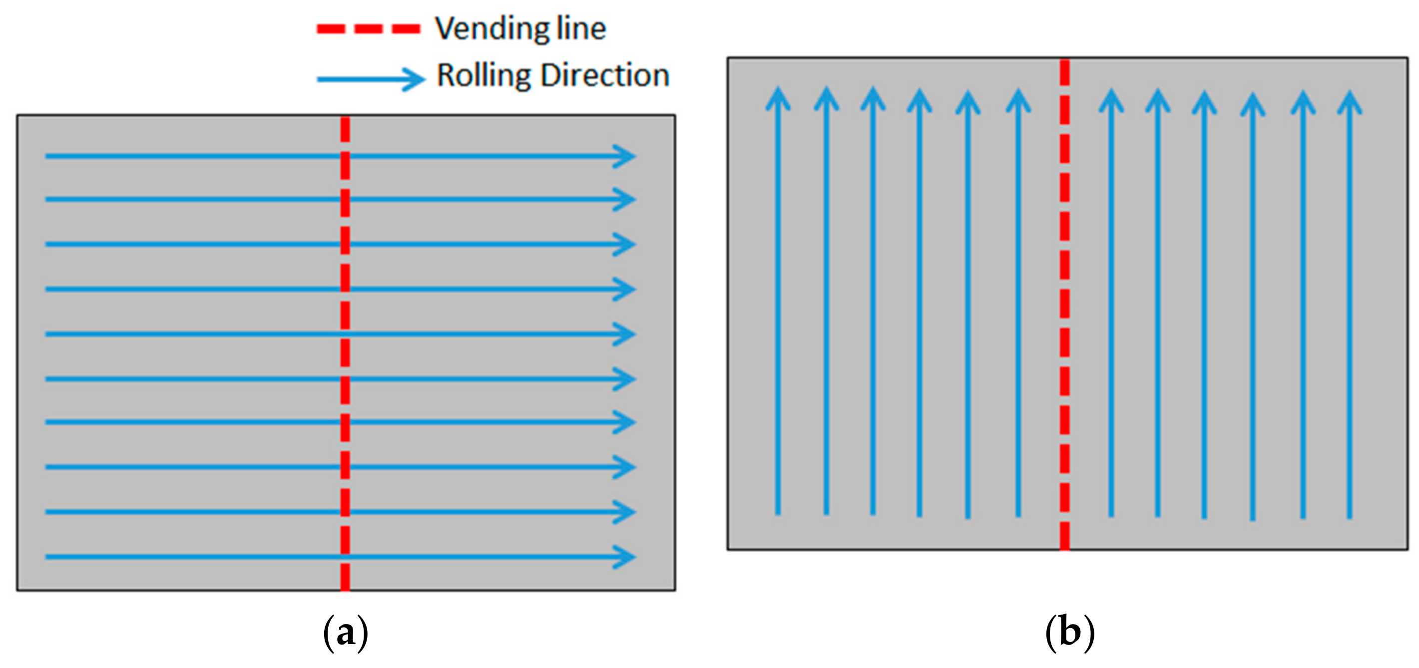
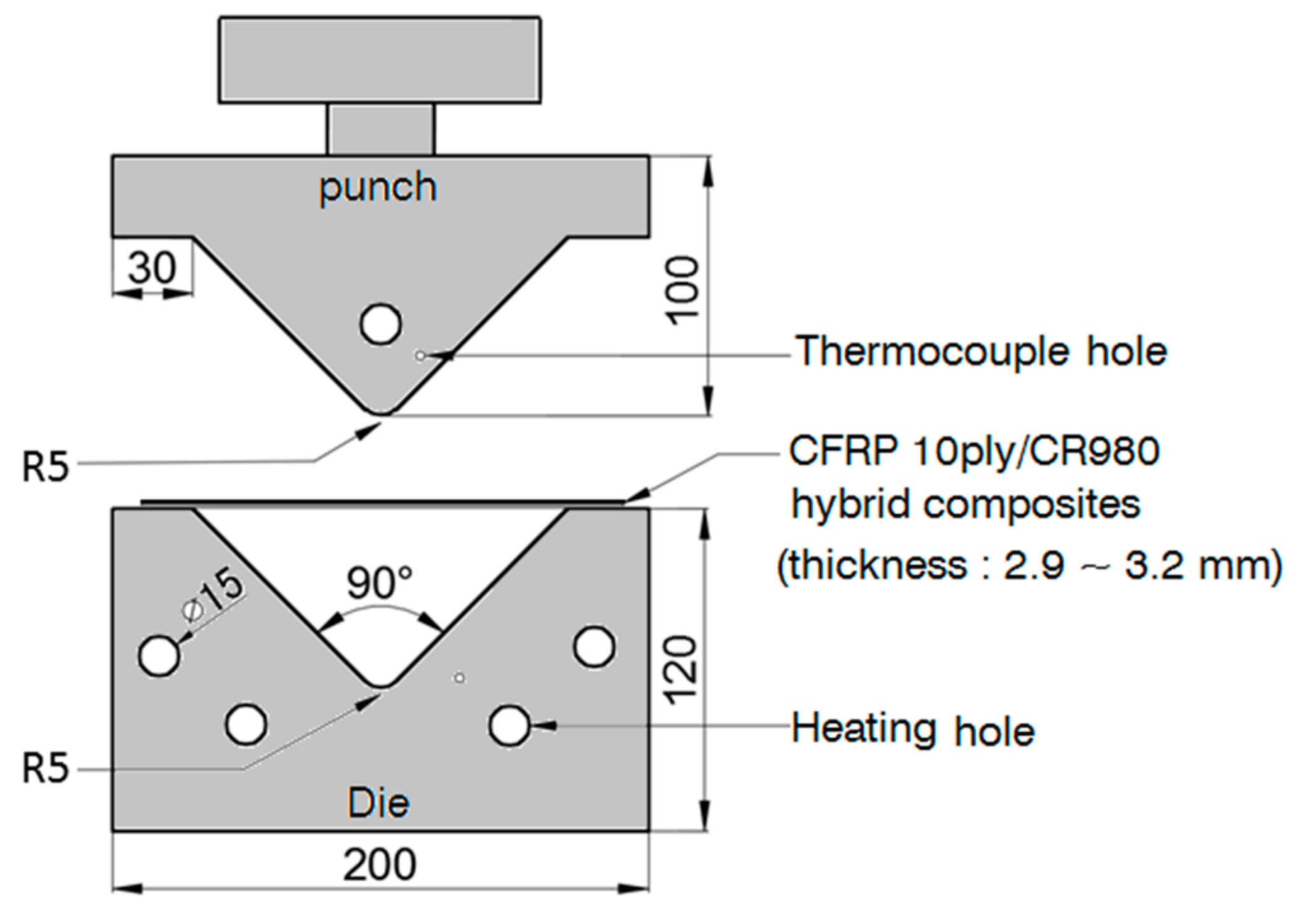
2.2. V-Bending Test of CFRP/CR980 Hybrid Composite

In order to measure spring-back of the CFRP/CR980 hybrid composite, V-bending experiments were conducted. Figure 5 shows a detailed view of the shape of the mold used in the V-bending test of the CFRP/CR980 hybrid composite. The mold was divided into an upper punch part and a lower die part. To control the temperature of the punch part and the die part, a hole was made for the heat cartridge to be inserted. The edge part of the die and punch have radius (R) of 5 mm. Table 4 lists the parameters of the V-bending test of the CFRP/CR980 hybrid composite. Experiments were conducted under 1 MPa and 2 MPa, respectively. The die temperature of 160 °C was maintained. After the V-bending specimen has been pressed and cured using constant pressure for 30 min, the V-bending angle was measured using a digital protractor from BLUEBIRD.
In case of the CR980 material produced by cold rolling, there is a difference in the mechanical property value and the elastic recovery amount according to the rolling direction. When V-bending was carried out in the direction parallel to the rolling direction, it was indicated as RD0°, while when V-bending was carried out in the vertical direction, it was indicated as RD90°. The concept of the rolling direction and V-bending is shown in Figure 6. The size of the specimen used in the V-bending experiment was set at 180 × 130 mm. The equipment used in the experiment was a 25-ton MTS.
Figure 7 shows a diagram of a spring-go phenomenon occurring in a direction opposite to that of a spring-back phenomenon, in accordance with the elastic recovery amount after the bending process of the plate material. In general, during V-bending by physical pressure, compressive stress occurs in the plate material at the punch portion of the mold, while tensile stress occurs at the die portion. As the punch ascends, the punch portion where the compressive stress occurs is restored to its original shape; conversely, the spring-back phenomenon occurs in the die portion, where the tensile stress occurs due to contraction.

3. Results

3.1. CFRP/CR980 Hybrid Composite by Shear Lap Adhesion Test

3.1.1. Bonding Strength

Figure 8 shows the bonding strength of CFRP/CR980 hybrid composites with different surface roughness conducted by the hot compression molding process under 1 MPa and 2 MPa of pressure. When the pressure was 1 MPa, the average bonding strength of the control was measured as 3.7 MPa. The bonding strengths were measured as 10.2 MPa, 15.2 MPa, 17.1 MPa, and 10.2 MPa when the surface roughness values were 20 μm, 35 μm, 45 μm, and 60 μm, respectively. When the pressing condition was 2 MPa, the average bonding strength of the untreated specimens was measured as 4.1 MPa, while when the surface roughness values were 20 μm, 35 μm, 45 μm, and 60 μm, and the bonding strengths were measured as 7.5 MPa, 9.2 MPa, 10.5 MPa, and 9.2 MPa, respectively.
As the surface roughness of the CR980 increased, it was found that the bonding strength of the CFRP/CR980 hybrid composite also increased. However, the bond strength decreased at the roughest surface of 60 μm. The bonding strength under 2 MPa of the pressure was lower than that under 1 MPa of the pressure. A possible reason for the decrease of the bonding strength could be the loss of epoxy, which is the matrix of the CFRP prepreg, and the largest factor in the bonding characteristics with increasing pressure applied to the specimens.
Figure 9 shows the specimens after Shear Lap adhesion test. Figure 9a is the specimen without sandblast treatment conducted by 1 MPa of the pressure and Figure 9b is the specimen with surface roughness (Rz = 45 μm) conducted by 1 MPa of the pressure. Fracturing from the shear lap adhesion test occurred at about 12 mm of the bonding area. In the case of a specimen with surface roughness, there was some epoxy and CFRP on the surface of CR980. On the other hand, the CR980 specimen without sandblast treatment had no epoxy and CFRP on the surface.

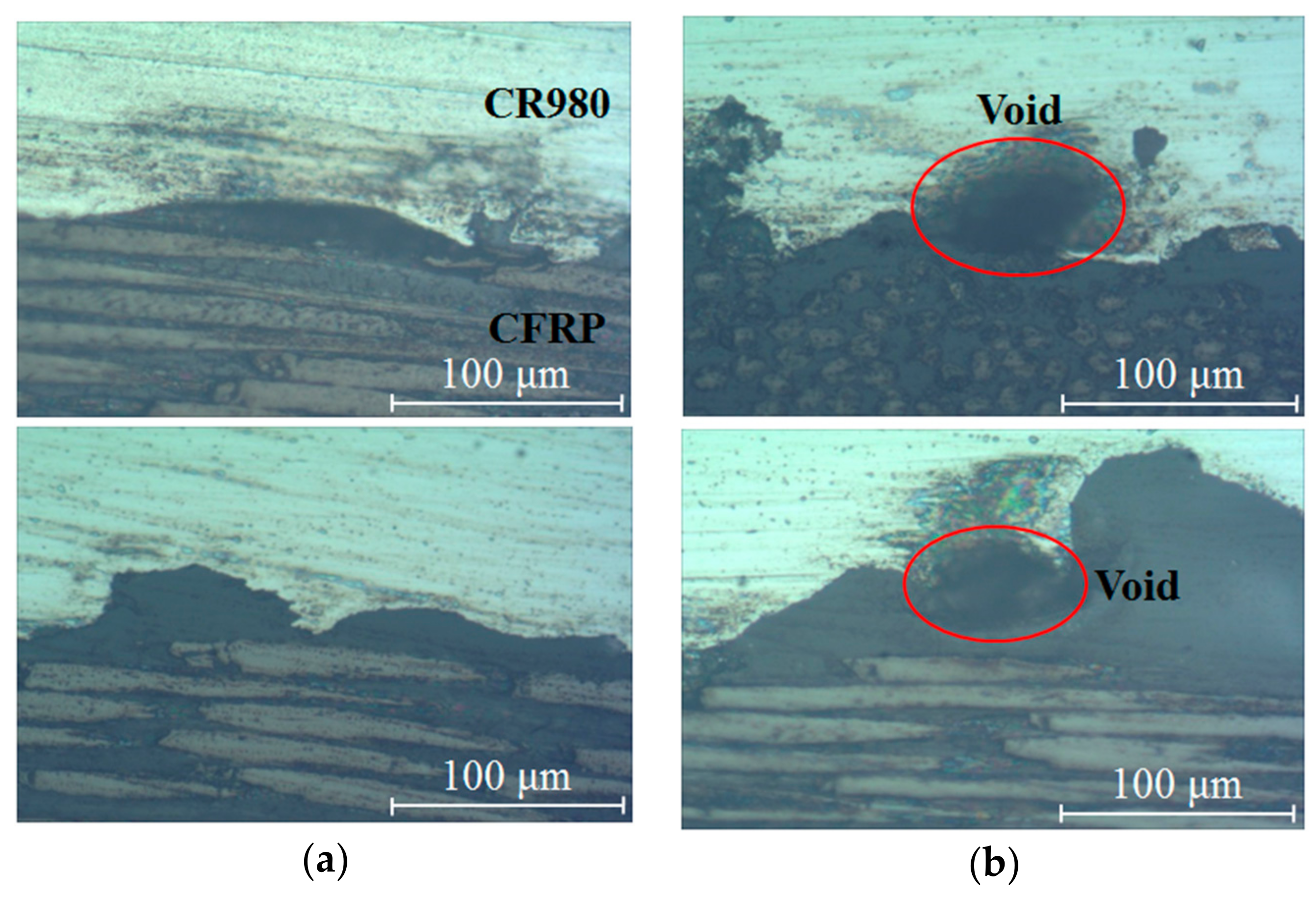
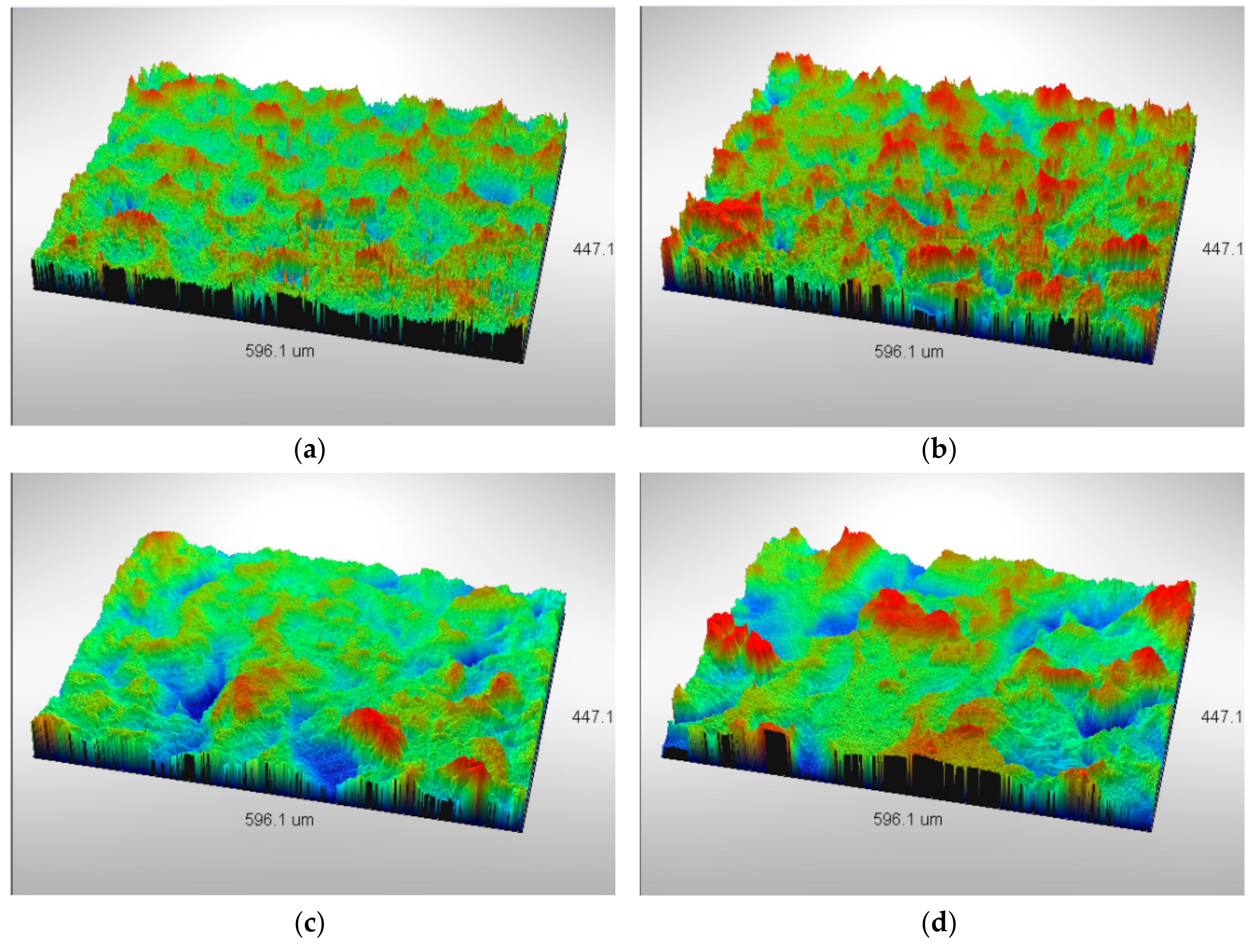
3.1.2. Microstructures

As can be seen from the bonding strength measurement experiment, the bonding strength of the CFRP/CR980 hybrid composite increases as the surface roughness of the CR980 increases. However, at Rz = 60 μm, which is the roughest surface, the bonding strength decreased under the condition of pressure forces of 1 MPa and 2 MPa.
To clarify the reason for the decrease in the bonding strength, photographs of the cross-section of the specimen with Rz = 45 μm, which is the surface roughness of CR980 with the highest bond strength, and the specimen with a surface roughness of 60 μm, whose bond strength decreased, were observed.
Figure 10 show photographs of the microstructure of the cross-section of the CFRP/CR980 hybrid composites. Figure 10a show the specimen with a surface roughness of 45 μm, while Figure 10b show the specimens with a surface roughness of 60 μm. In the specimen with the highest bonding strength with surface roughness Rz = 45 μm, dark gray epoxy was evenly distributed at the interface of the bonding of CFRP and CR980, indicating that the epoxy effect the increase in bonding strength. The specimen with Rz = 60 μm shows the roughest surface treatment, which means that the surface roughness increased compared with the specimen with Rz = 45 μm. As the surface roughness increases, epoxy, which affects the bonding strength, cannot be uniformly impregnated, and pores are generated. It can be observed that the bonding strength of the specimen having the roughest surface (Rz = 60 μm) decreased.

3.2. CFRP/CR980 Hybrid Composite by V-Bending Test
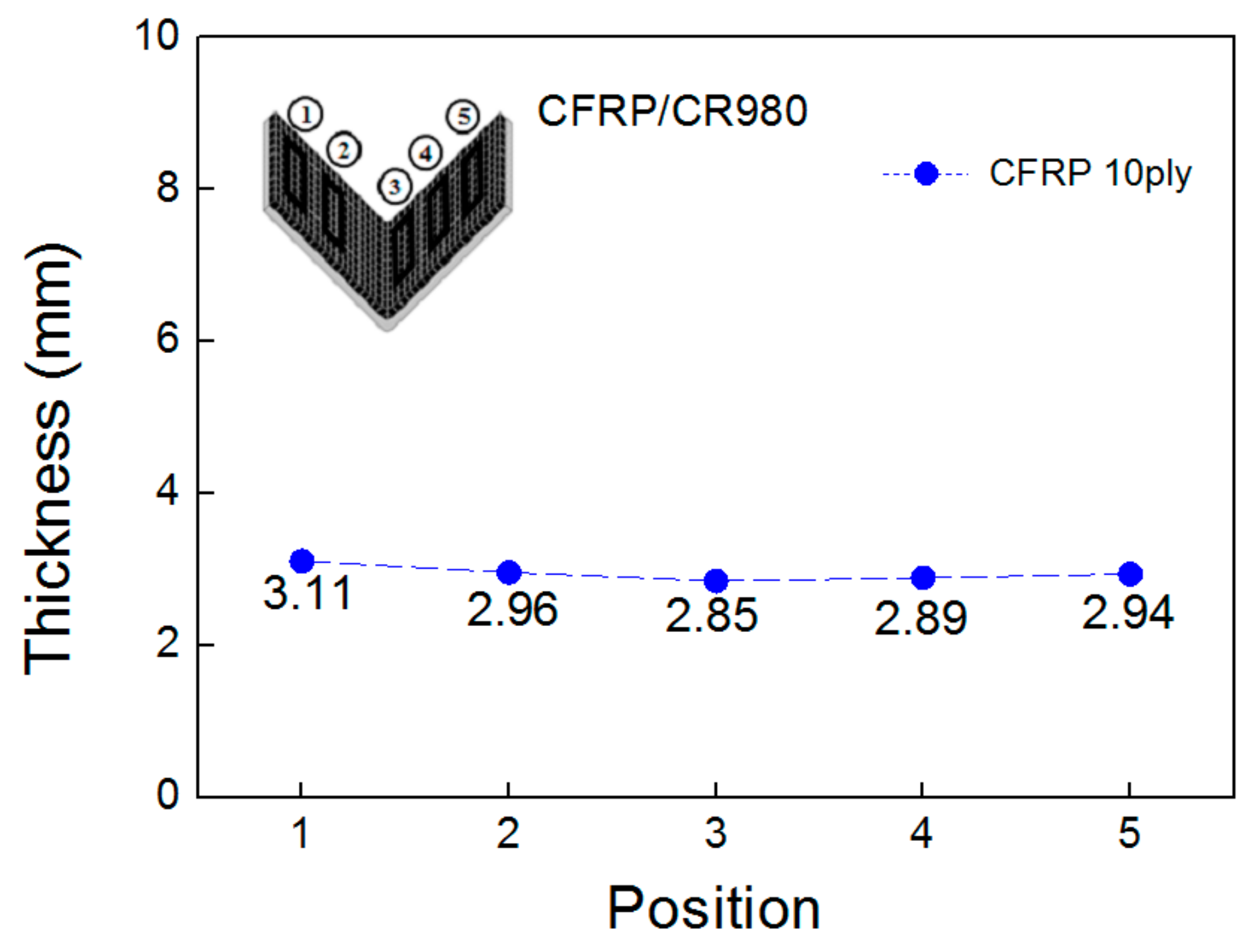
3.2.1. Thickness

Figure 11 shows the thickness of the CFRP/CR980 hybrid composite conducted by V-bending at different positions. When the number of laminations of the CFRP prepreg was 10, the thickness was in the range of 2.85–3.11 mm. In general, a thickness of 2–3 mm is suitable for use in automotive pillar and subframe components. To meet these requirements, the use of CR980 1.2 mm material and 10 sheets of CFRP prepreg to reduce the overall thickness of the latter half part from 2 mm to approximately 3 mm, is proposed as the most suitable layer for the part. In addition, the thickness of the CFRP/CR980 hybrid composite tends to be thicker at the side of the specimen than at the center of the specimen, which could be due to the concentration of pressure at the center than at the side of the punch and die.

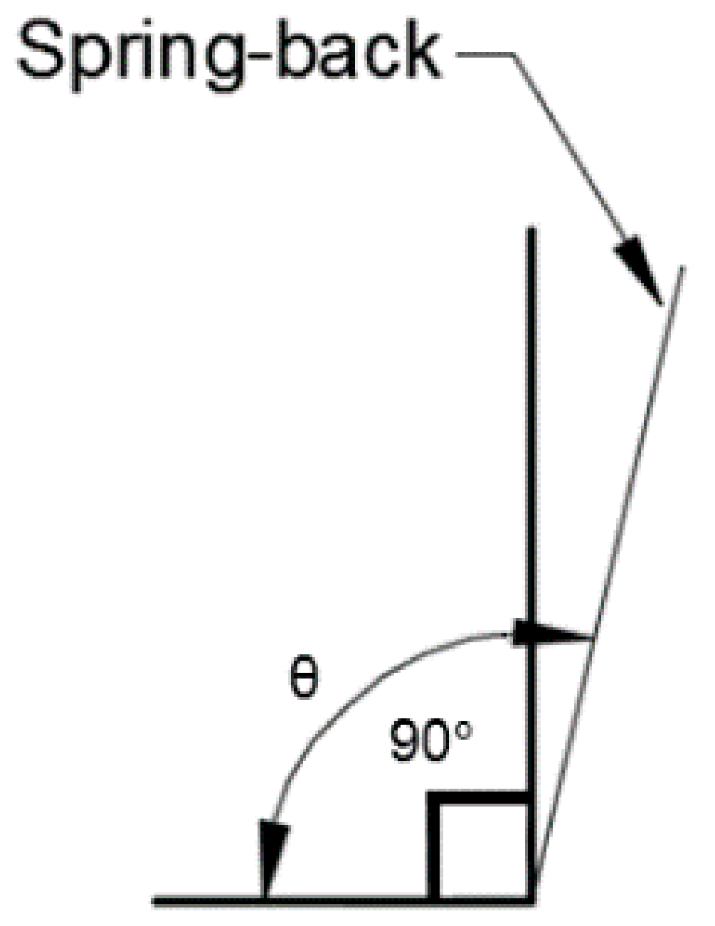
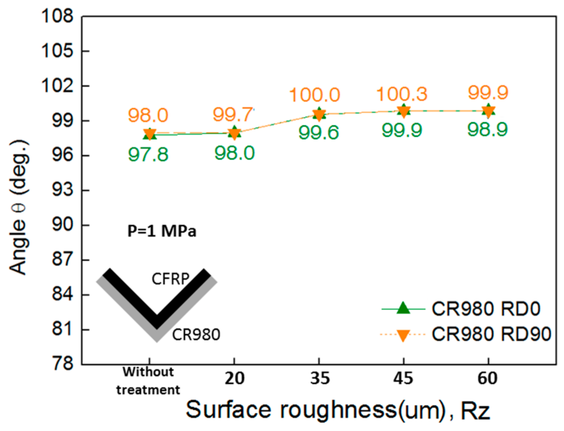
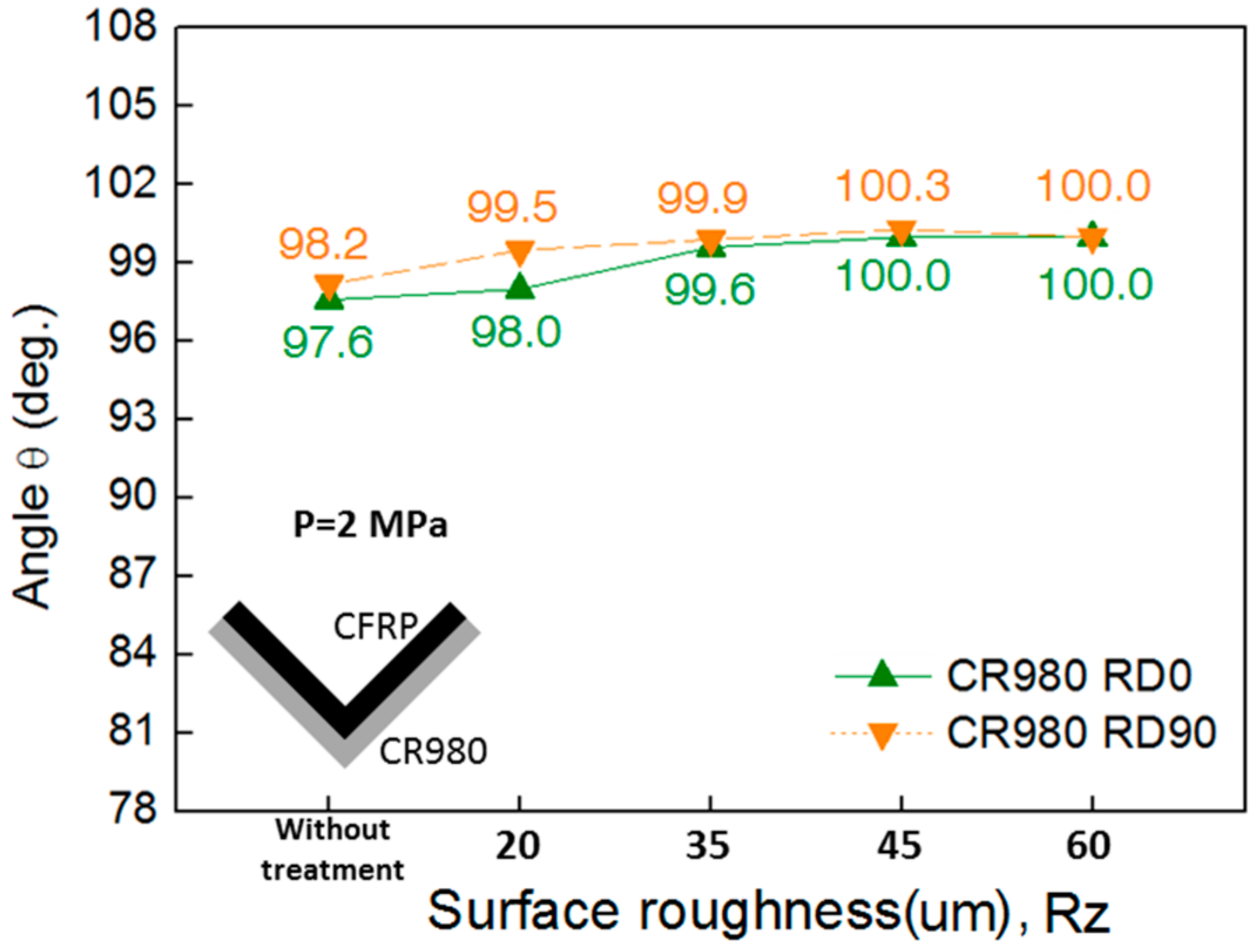
3.2.2. Spring-Back Angle

The punch with a V-shape loading, puts a concentrated load on CFRP/CR980 hybrid composite and does get dispersed evenly before causing any damage. Figure 12 shows the spring-back angle of the CFRP/CR980 hybrid composite with different surface roughness conducted by a V-bending test under 1 MPa of the pressure. As the surface roughness values increased to 20 μm, 35 μm, 45 μm, and 60 μm, when the number of lamination of CFRP was 10, the rolling direction was 0° (RD0°) and the pressure force was 1 MPa, the spring-back angles were 97.8°, 98.0°, 99.6°, 99.9°, and 98.9°, respectively. As the surface roughness increased, the spring-back angle also increased. Similarly, when the rolling direction was 90° (RD90°), the spring-back angles were 98.0°, 99.7°, 100°, 100.3°, and 99.9°, respectively. The spring-back angle was larger in the rolling direction of 90° (RD90°) than 0° (RD0°).
Figure 13 shows the spring-back angle of the CFRP/CR980 hybrid composite with different surface roughness conducted by a V-bending test under 2 MPa of the pressure. When the number of laminations of the CFRP was 10, the rolling direction was 0° (RD0°) and pressure force was 2 MPa; then, as the surface treatment condition increased without treatment to Rz = 20 μm, 35 μm, 45 μm, and 60 μm, the spring-back angle increased to 97.6°, 98.0°, 99.6°, 100.0°, and 100.0°, respectively. Overall, as the surface roughness increased, the spring-back also increased. Similarly, when the rolling direction was 90° (RD90°), the spring-back also increased. The spring-back angle was larger when the rolling direction was 90° (RD90°) than when it was 0° (RD0°). Choi et al. present that the spring-back angles were 93.9° (RD0°) and 93.7° (RD90°) at the V-bending test of CFRP 10ply/CR340 without treatment under 0.5 MPa, 140 °C, and 30 min of curing [21]. The spring-back angles of CFRP/CR980 were slightly higher than CFRP/CR340, though the process parameters were a little different.

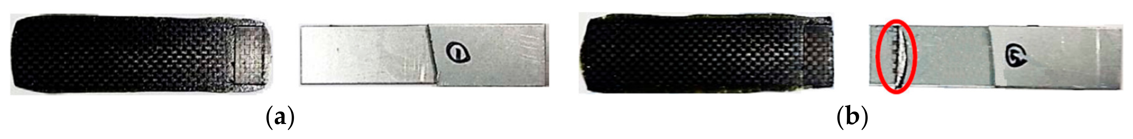
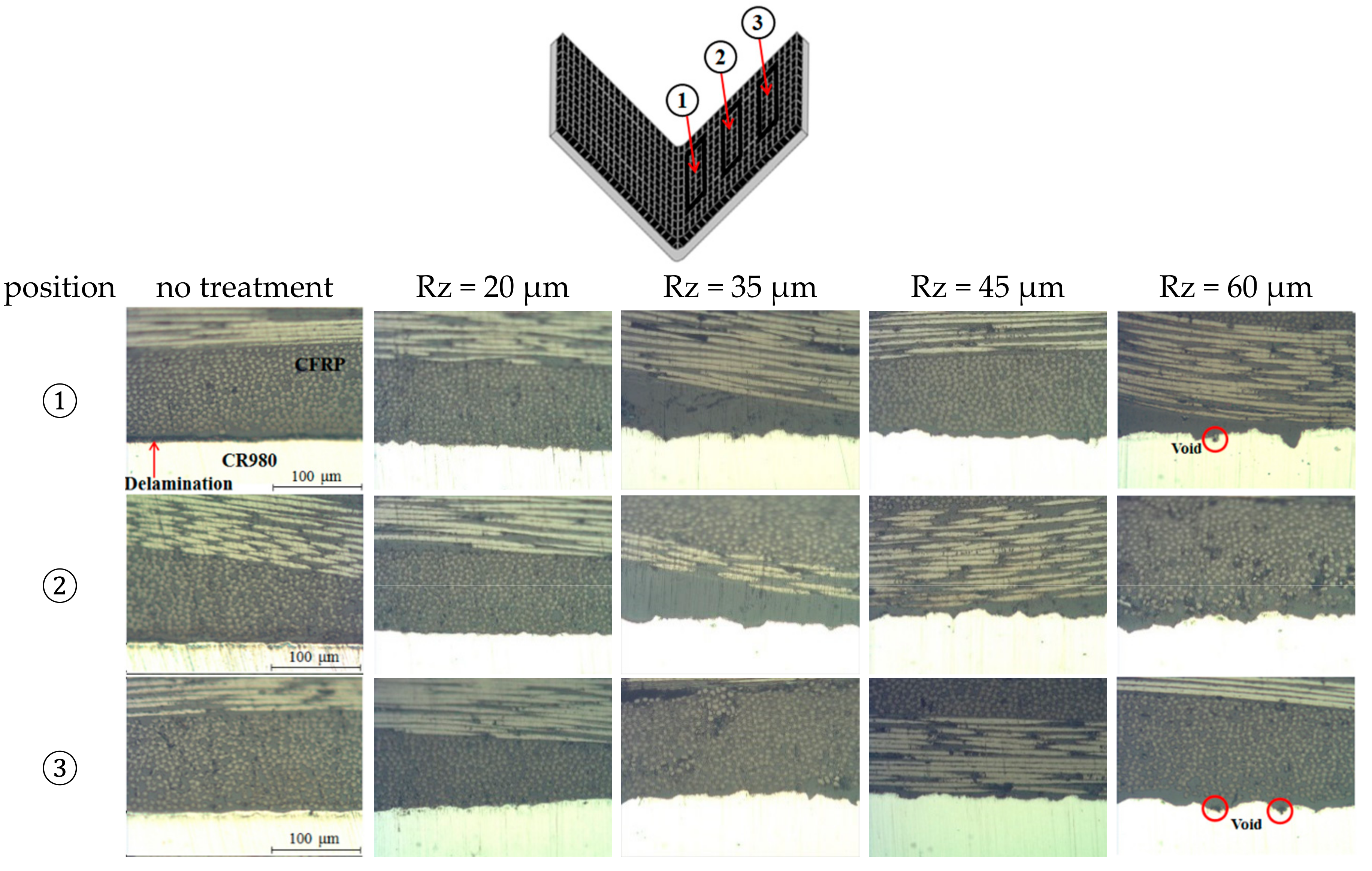
3.2.3. Microstructures

Figure 14 shows microstructures at different positions of the CFRP/CR980 hybrid composite, conducted by a V-bending test under 1 MPa of the pressure. Position ① shows the nearest area of curvature of the punch and die part. As a result, it can be observed at position ① that delamination occurred at the bonding interface of the CFRP and CR980 without treatment. In case of the conditions of Rz = 20 μm, 35 μm, 45 μm, and 60 μm, no delamination was observed. However, under the Rz = 60 μm condition, it can be considered that pores were formed because epoxy, which is a matrix of the CFRP prepreg, could not be uniformly impregnated on the surface. Position ② shows the middle area of the CFRP/CR980 hybrid composite. Delamination at the interface of the CFRP and CR980 did not occur at position ②. Position ③ shows the edge area of the CFRP/CR980 hybrid composite. No delamination phenomenon was observed, despite changes in the roughness of the CR980 and without treatment conditions. However, the condition of Rz = 60 μm shows that epoxy was not uniformly impregnated on the surface of the CR980, and pores were observed. The interface bond strength between the matrix and CFRP prepreg had a significant effect on the surface roughness.

4. Conclusions

In this study, the bonding strength and the spring-back of the CFRP/CR980 hybrid composite was investigated:
(1)
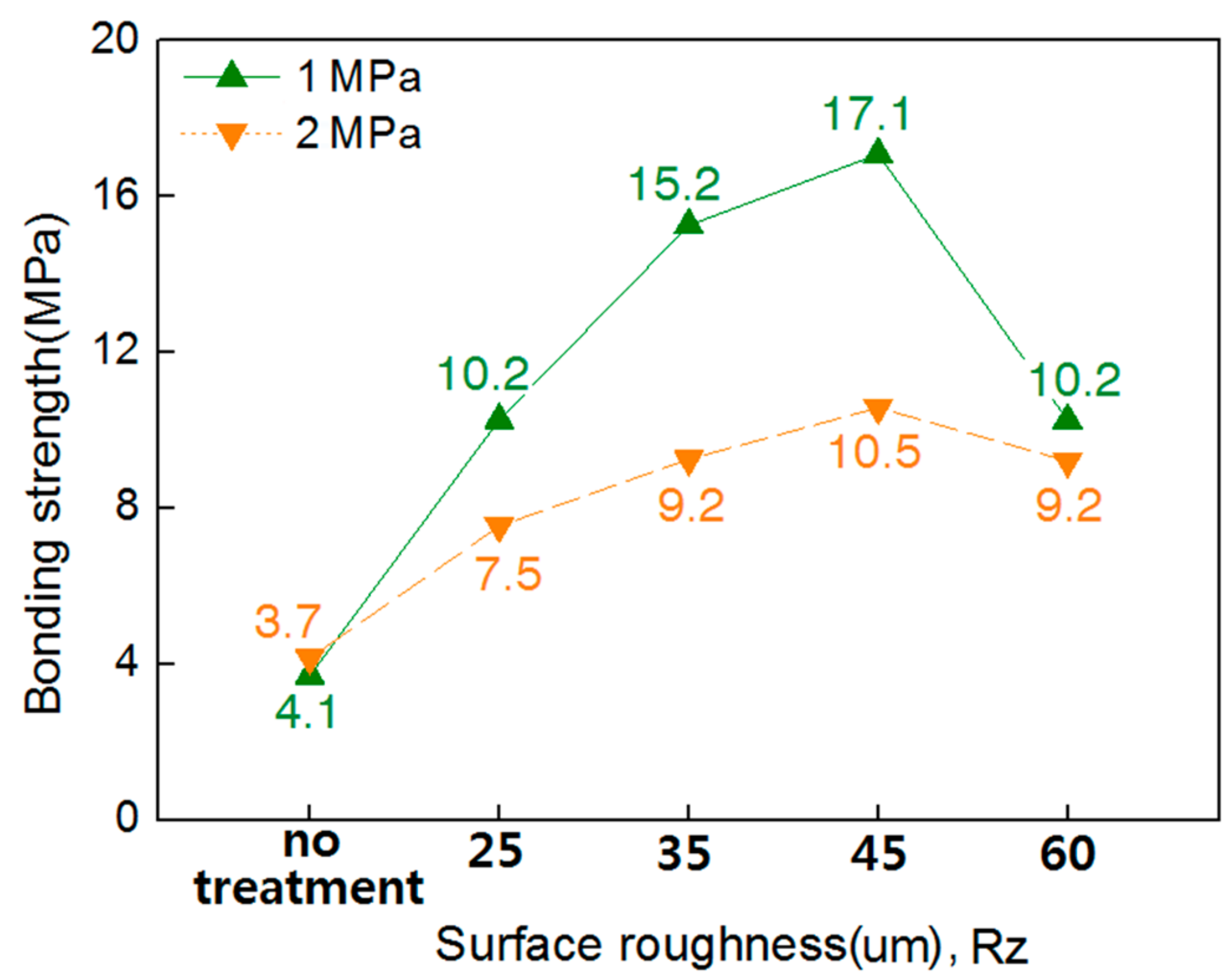
The bonding strength between the surface-treated CR980 and CFRP generally increased depending on the degree of surface treatment. In the condition of Rz = 60 μm or more, the bonding strength was reduced.
(2)
The bonding strength of specimens pressurized at 2 MPa was lower than that at 1 MPa, when pressure was applied during the production of shear test specimen to measure the bond strength.
(3)
The spring-back angle tended to increase with an increase in the surface roughness. There is a little bit of difference in spring-back angles between 1 MPa and 2 MPa of the pressure.
(4)
Delamination occurred at the bonding interface near the punch contact area of the CFRP/CR980 hybrid composite without treatment under 1 MPa of the pressure.

Author Contributions

J.H.H. and C.K.J. designed the experiment tools and performed the experiment. C.K.J., M.S.L., and S.W.C. analysed the experimental results, whereas Chung Gil Kang maintained and examined them. All authors have contributed to the discussions as well as revisions.

Acknowledgments

This work was supported by the National Research Foundation of Korea (NRF) grant funded by the Korean government (MSIP) through the GCRC-SOP (No. 2011-0030013). This work was also supported by the National Research Foundation of Korea (NRF) grant funded by the Korea government (MSIT) (No. 2017R1A2B4007884). This work was also supported by the National Research Foundation of Korea Grant funded by the Korean Government (NRF-2017R1C1B5017242).

Conflicts of Interest

The authors declare no conflict of interest.

References

  1. Lightweighting-Wikipedia. Available online: https://en.wikipedia.org/wiki/Lightweighting (accessed on 1 September 2018).
  2. Lightweight-Materials-Cars-and-Trucks/Department of Energy. Available online: https://www.energy.gov/eere/vehicles/lightweight-materials-cars-and-trucks (accessed on 1 September 2018).
  3. Al-Zubaidy, H.; Zhao, X.L.; Al-Mihaidi, R. Mechanical Behaviour of Normal Modulus Carbon Fibre Reinforced Polymer (CFRP) and Epoxy under Impact Tensile Loads. Procedia Eng. 2011, 10, 2453–2458. [Google Scholar] [CrossRef]
  4. Van-Paepegem, W.; De-Geyter, K.; Vanhooymissen, P.; Degrieck, J. Effect of friction on the hysteresis loops from three-point bending fatigue tests of fibre-reinforced composites. Compos. Struct. 2006, 72, 212–217. [Google Scholar] [CrossRef]
  5. Kleiner, M.; Geiger, M.; Klaus, A. Manufacturing of Lightweight Components by Metal Forming. CIRP Ann.-Manuf. Technol. 2003, 52, 521–542. [Google Scholar] [CrossRef]
  6. Fuwa, M.; Bunsell, A.R.; Harris, B. Tensile failure mechanisms in carbon fibre reinforced plastics. J. Mater. Sci. 1975, 10, 2062–2070. [Google Scholar] [CrossRef]
  7. Paiva, J.M.F.; Mayer, S.; Rezende, M.C. Comparison of Tensile Strength of Different Carbon Fabric Reinforced Epoxy Composites. Mater. Res. 2006, 9, 83–89. [Google Scholar] [CrossRef]
  8. Yu, T.; Fernando, D.; Teng, J.G.; Zhao, X.L. Experimental study on CFRP-to-steel bonded interfaces. Compos. Part B Eng. 2012, 43, 2279–2289. [Google Scholar] [CrossRef]
  9. Lee, M.S.; Kim, S.J.; Lim, O.D.; Kang, C.G. Effect of process parameters on epoxy flow behavior and formability with CR340/CFRP composites by different laminating in deep drawing process. Procedia Eng. 2014, 81, 1627–1632. [Google Scholar] [CrossRef]
  10. Lee, M.S.; Kim, S.J.; Kim, H.H.; Lim, O.D.; Kang, C.G. Effects of process parameters on epoxy flow behavior and formability in deep drawing process with CR340/carbon fiber–reinforced plastic composites. Proc. Inst. Mech. Eng. B J. Eng. Manuf. 2014, 229, 86–99. [Google Scholar] [CrossRef]
  11. High Performance Carbon Fibers—National Historic Chemical Landmark. Available online: https://www.acs.org/content/acs/en/education/whatischemistry/landmarks/carbonfibers.html (accessed on 1 September 2018).
  12. Fan, L.-T.; Gharpuray, M.M.; Lee, Y.H. Nature of Cellulosic Material. Cellul. Hydrolys. 1987, 3, 5–20. [Google Scholar]
  13. Via, B.K.; So, C.L.; Shupe, T.F.; Groom, L.H.; Wikaira, J. Mechanical response of longleaf pine to variation in microfibril angle, chemistry associated wavelengths, density, and radial position. Compos. Part A Appl. Sci. Manuf. 2009, 40, 60–66. [Google Scholar] [CrossRef]
  14. Wei, P.; Rao, X.; Yang, J.; Guo, Y.; Chen, H.; Zhang, Y.; Wang, Z. Hot pressing of wood-based composites: A review. For. Prod. J. 2016, 66, 419–427. [Google Scholar] [CrossRef]
  15. Lee, M.S.; Kim, S.J.; Lim, O.D.; Kang, C.G. A study on mechanical properties of Al5052/CFRP/Al5052 composite through three-point bending tests and shear lap tests according to surface roughness. J. Compos. Mater. 2016, 10, 1–11. [Google Scholar] [CrossRef]
  16. Korea Carbon. Available online: https://www.hcarbon.com/product/overview.asp (accessed on 1 September 2018).
  17. Toray. Available online: https://www.toray.com/products/prod_001.html (accessed on 1 September 2018).
  18. Hyundai Steel. Available online: https://www.hyundai-steel.com/kr/products-technology/products/hotrolledsteel.hds (accessed on 1 September 2018).
  19. Korean Agency for Technology and Standard. Methods of Making Samples of Carbon Fiber Reinforced Plastics; KS M 3713; KATS: Seoul, Korea, 2012. [Google Scholar]
  20. Standard Guide for Testing Polymer Matrix Composite Materials; ASTM D4762-16; ASTM International: West Conshohocken, PA, USA, 2011.
  21. Choi, S.W.; Lee, M.S.; Kang, C.G. Effect of process parameters and laminating methods on spring-back in V-bending of CFRP/CR340 hybrid composites. Int. J. Precis. Eng. Manuf. 2016, 17, 395–400. [Google Scholar] [CrossRef]
Figure 1. Schematic diagram of the equipment for fabricating carbon fiber-reinforced plastic (CFRP) using 10 pre-impregnated composite fibers (prepregs) (unit: mm).
Metals 08 00716 g001
Figure 2. A method of making test specimens for bonding strength measurements, and a schematic diagram of shear testing: (a) CFRP 10-ply; (b) CFRP/CR980 and dummy sheet laminating; (c) hot compression molding; (d) shear lap adhesion test.
Metals 08 00716 g002
Figure 3. Fabricated specimen for shear lap adhesion test.
Metals 08 00716 g003
Figure 4. Surface roughness images of CR980 conducted by sandblast: (a) Rz = 20 μm; (b) Rz = 35 μm; (c) Rz = 45 μm; (d) Rz = 60 μm.
Metals 08 00716 g004
Figure 5. Drawing of mold for V-bending test of CFRP/CR980 hybrid composites (unit: mm).
Metals 08 00716 g005
Figure 6. Rolling direction of CR980 for V-bending test: (a) 90° (RD90°); (b) 0° (RD0°).
Metals 08 00716 g006
Figure 7. A conceptual view of the spring-back.
Metals 08 00716 g007
Figure 8. Bonding strength of CFRP/CR980 hybrid composites with different surface roughness conducted by hot compressing under different pressures.
Metals 08 00716 g008
Figure 9. Specimens after the shear lap adhesion test (bonding pressure: 1.0 MPa): (a) without sandblast treatment; (b) with surface roughness (Rz = 45 μm).
Metals 08 00716 g009
Figure 10. Microstructures (section view) CFRP/CR980 hybrid composites conducted by shear lap adhesion test: (a) surface roughness Rz = 45 μm; (b) surface roughness Rz = 60 μm.
Metals 08 00716 g010
Figure 11. The thickness of the CFRP/CR980 conducted by V-bending test at different positions.
Metals 08 00716 g011
Figure 12. Angle of spring-back of CFRP/CR980 hybrid composites with different levels of surface roughness, conducted by a V-bending test under 1 MPa of the pressure.
Metals 08 00716 g012
Figure 13. Angle of spring-back of CFRP/CR980 hybrid composites with different levels of surface roughness, conducted by a V-bending test under 2 MPa of the pressure.
Metals 08 00716 g013
Figure 14. Microstructures (section view) at different positions of CFRP/CR980 hybrid composites conducted by a V-bending test.
Metals 08 00716 g014
Table 1. Mechanical properties of CFRP prepreg (CF3327EPC, HANKUK CARBON) [16].
ConstructionWeight of Carbon FiberWeight of ResinResin ContentTotal WeightFabric Thickness
Plain205 g/m2150 gr/m242 ± 2%352 gr/m20.27 ± 0.05 mm
Table 2. Mechanical Properties of carbon fiber (T300-3K-50, TORAY INDUSTRIES Inc., Tokyo, Japan) and CR980 Steel (SPFC980Y, HYUNDAI STEEL, Seoul, Korea) [17,18].
ConstructionYield StrengthTensile StrengthElongationElastic Modulus
3K Carbon fiber 3530 MPa1.5%E1 = 135 GPa, E2 = 10 GPa
SPFC980Y(RD0°)568 MPa900 MPa18.8%200 GPa
(RD90°)619 MPa1043 MPa18.0%
Table 3. Parameters of the hot compression molding process.
Surface Roughness (Rz) between CFRP and CR980PressureTemperature of MoldCurring Time
20, 35, 45, 60 μm1, 2 MPa160 °C30 min
Table 4. Parameters of the V-bending test of the CFRP/CR980 hybrid composite.
PressureTemperature of MoldCurring TimeDirection of CR980 Sheet
1, 2 MPa160 °C30 minRD0°, RD90°

