Article

Role of Chemical Composition in Corrosion of Aluminum Alloys

1
Faculty of Mechanical Engineering, Department of Materials Engineering, University of Žilina, Univerzitná 8215/1, 010 26 Žilina, Slovakia
2
Faculty of Transport Engineering, University of Pardubice, Studentská 95, 532 10 Pardubice, Czech Republic
*
Author to whom correspondence should be addressed.
Metals 2018, 8(8), 581; https://doi.org/10.3390/met8080581
Submission received: 4 July 2018 / Revised: 19 July 2018 / Accepted: 23 July 2018 / Published: 26 July 2018
(This article belongs to the Special Issue Non-Ferrous Metallic Materials)

Abstract

:
Aluminum alloys are the most important part of all shaped castings manufactured, especially in the aerospace and automotive industries. This work focuses on the corrosion properties of the heat-hardening aluminum alloys commonly used for production of automotive castings AlSi7Mg0.3 and on self-hardening AlZn10Si8Mg. Iron is a common impurity in aluminum cast alloy and its content increases by using secondary aluminum alloys. Therefore, experimental materials were developed, with chemical composition according to standards (primary alloys) and in states with an increasing content of Fe. The experimental aluminum alloys are briefly discussed in terms of their chemical composition, microstructure, mechanical properties and corrosion behavior. Corrosion properties were examined using three types of corrosion tests: exposure test, potentiodynamic tests, and Audi tests. Corrosion characteristics of materials were evaluated using stereo, optical and scanning electron microscopy, energy dispersive X-ray analysis, too. Correlation of pit initiation sites with microstructural features revealed the critical role of iron-rich phases, silicon particles and corresponding alloy matrix.

1. Introduction

The modern world requires the use of light structural materials to improve fuel economy, energy consumption and emissions of gas in industrial application [1]. The properties (low density, high strength stiffness to weight ratio, good formability and good corrosion resistance) make aluminum alloys an ideal material for the manufacturing of components for automotive and aerospace applications [2,3,4,5]. The main components of internal combustion engines such as cylinder head, cylinder block, crankshaft and pistons are the main automotive components where aluminum cast alloys are used. The importance is to achieve the requested properties, which do not depend only on the casting condition and solidification rate, but they are also significantly influenced by their chemical composition. The chemical composition leads to the formation of different microstructural features. From this point of view the most important features are α-matrix (dendrite cell size, secondary dendrite arm spacing-SDAS, grain size), eutectic silicon particles and intermetallic phases (size, morphology, amount) and porosity [3,4,6,7]. Osório et al. [5,6] investigated that the dendrite fineness can be even of more importance in the mechanical properties compared to the effect of grain size. It was also reported that unmodified samples of as-cast and heat-treated conditions reached higher corrosion resistance than the modified samples. On the other hand, research shows that the T4 heat treatment provides a recovery on the corrosion resistance due to the spheroidizing effect on silicon particles. Tahamntan et al. [8] explained morphological aspects of silicon phase as well as the area effect as related to galvanic corrosion between silicon particles and eutectic aluminum phase.
The other microstructural features which significantly affect the properties of aluminum castings are intermetallic phases. Intermetallic phases improve or decrease mechanical and physical properties which depend on the morphologies, type and distribution of these phases that are in turn a function of alloy composition and cooling rate [9,10]. Donatus et al. [11] showed that intermetallic particles such as the Al2CuMg, Al3Mg2, Mg2Si, and MgZn2 are anodic to the Al matrix and corrode preferentially with respect to the surrounding Al matrix. The intermetallic phases particles such as Al2Cu (θ), AlFeMnSi, AlCuFeMn, AlCuFeSi, and (Al,Cu)x(Fe,Mn)ySi particles which are mostly cathodic to the Al matrix and cause peripheral trenches of the surrounding Al matrix adjacent to these intermetallic phase particles. The element represented the major classes of intermetallic phases and caused a decrease in aluminum alloy properties is Fe. Iron has to be considered in industrially processed alloys as well, since it is usually presented as impurities, stemming from impurities in bauxite ore and contamination with ferrous metals and oxides during handling and recycling. The most significant is the presence of iron in aluminum cast alloys because of reducing adhesion to metal molds [12]. Due to their low solubility (only 0.05% at 660 °C), these can have a negative effect on formability by forming large “constituent” particles (Al-Fe-Si) during eutectic solidification [4,13,14]. Removing Fe from the melts is a very expensive process [15]. Therefore, it is important to study how these elements influence the properties of Al-Si castings. Phases of Al-Fe-Si-Mg, which crystallize in the form of so-called ‘‘Chinese script”, are iron-magnesium phases that also behave in a cathodic manner regarding the α-matrix, although they are expected to be less detrimental than Al-Fe, Al-Fe-Si and Al-Fe-Si-Mn due to the presence of magnesium. The strengthening phase of Mg2Si is anodic regarding the aluminum matrix and it may enhance localized corrosion [4,16,17]. Other microstructural features affect the properties of final aluminum casts–e.g., porosity, the most common defect in Al-Si castings [9,13]. Taylor et al. [18] reported the specific effect of Fe needle phases on porosity: the total porosity is minimized at 0.4 % Fe; a localized shrinkage-porosity defect (termed the “extended defect”) develops at iron concentrations greater than 0.4% under no optimum casting conditions; and there is a change from a discrete pore morphology at 0.1% Fe content to zones of sponge-like interdendritic porosity at higher iron levels. Samuel et al. [13] examined that further increase in the iron content, and hence the size of the β-Al5FeSi platelets, cause an increase in pore sizes, however the platelets also limit pore growth.
Mechanical and fatigue properties of aluminum alloys used in the automotive and aerospace industry were examined in many works [2,5,6,12,19,20]. Corrosion is not considered a big problem for aluminum castings due to their high material thickness. Therefore, corrosion properties of aluminum castings were not investigated to the same extent as wrought aluminum alloys. For the future, we will still need to think about decreasing vehicle weight, and economic demands for production in the automotive industry. This can be achieved by reducing the material thickness. Thus, corrosion properties will be of vital importance for the properties and a life-time of such components. On the other hand, it is most likely that pitting corrosion or other forms of localized corrosion attack enhanced fatigue crack initiation [21]. Properties of final aluminum products are more important from the point of view of the usage of aluminum casts in industries. Therefore, the aim of the present study is to contribute to the understanding of the microstructural arrangement role on the corrosion resistance of different hypoeutectic secondary Al cast alloys.

2. Materials and Methods

Al-Si based alloys are the most significant commercial casting alloys (basic materials for cylinder heads are especially AlSiMg and AlSiCu cast alloys) [22,23]. These materials are suitable for heat treatment and can reach the required mechanical properties [9,24]. Thanks to its excellent foundry properties, the hypoeutectic AlSi7Mg0.3 cast alloy was an object of the research. Experimental alloys, with the chemical composition reported in Table 1, have been produced by gravity casting at Uneko, spol.s.r.o., Zátor, Czech Republic, and cast into sand molds. Such alloys are commonly used in the production of components of the aerospace industry, automotive castings-wheels, engine parts, and so on. However, with the increased usage of recycling this material was produced with different iron concentrations. The alloy was produced according to the standard 0.123 wt. % of Fe (alloy A), with the content of 0.454 wt. % Fe (alloy B) and with the content of 0.655 wt. % Fe (alloy C). The content of Fe was defined by the company based on the input raw materials and economical point (Table 1).
Contemporary manufacturers would like to lower the economic demands of their manufacturing; therefore, makes sense to use self-hardened (without heat treatments) alloys. This class of alloys has a particular characteristic: they are subjected to a natural ageing phenomenon and after a period of about 7 to 10 days can achieve good final mechanical properties without any further thermal treatment [2,25,26]. This is a good opportunity to reduce the final production costs. Therefore, the second experimental material was AlZn10Si8Mg (UNIFONT 90). The AlZn10Si8Mg material was produced with a higher Fe content. Alloy D-AlZn10Si8Mg was prepared according to standard (0.150 wt. % Fe), and E-AlZn10Si8Mg was produced with the content of Fe 0.559 wt. %.
Experimental alloys, with the chemical composition reported in Table 1, were produced by gravity casting. According to the requirements, the material is not modified and grain refined. The experimental material was observed in form of bars with a 20 mm diameter and 280–300 mm length. Its mechanical properties (ultimate tensile strength, Brinell hardness, ductility), microstructure and corrosion resistance of the prepared samples with different content of Fe were investigated.
The test specimens with dimensions corresponding to the standards (ISO 6892-1:2009) for measuring the ultimate tensile strength (UTS) and specimens for corrosion properties with 10 mm diameter and 17.50 mm length. Changes in tensile properties (UTS and ductility) were measured on INSTRON Model 5985 according to the standard ISO 6892-1:2009. Test rates and control are set according to the A Method recommended ranges. The template is intended for specimens that produce a clearly defined linear elastic region and homogenous deformation. The calculated results include UTS and ductility. Hardness measurement for secondary aluminum alloy was performed by using a Brinell hardness tester with load of 250 kp (1 kp = 9.80665 N), a 5 mm testing ball, and a dwell time of 15 s. The evaluated UTS, ductility and Brinell hardness reflect the average values of at least six separate measurements for each experimental material.
Three different pre-exposing environments were included in order to elucidate the important relationship between the material and environment. The first was an exposure test in 3.5 wt. % NaCl solution at 20 °C for three weeks. Each specimen of the experimental material was degreased in ethanol before testing, and then dried. Potentiodynamic (PP) testing was chosen to evaluate the electrochemical corrosion characteristics. Each specimen of the experimental material was degreased in ethanol, and then dried before testing. Measurements were performed in the 0.5 M NaCl at 20 ± 2 °C, using laboratory potentiostat VSP Biologic SAS (Univesity of Žilina, Žilina, Slovakia). The three-electrode cell system was used, including an experimental specimen with the exposed area of 1 cm2 set as the working electrode, a platinum electrode was set as a counter and saturated calomel electrode (SCE), which served as a reference electrode (+0.242 V vs. platinum electrode). The PP tests started after 10 min of potential stabilization—between the experimental specimen and the testing electrolyte. The applied potential ranged from −200 mV to +300 mV. The range of potentials was set with respect to the open circuit potential (OCP) and the scan rate was 0.2 mV/s. The measured data in form of potentiodynamic curves were analyzed by the Tafel extrapolation method, and the values of corrosion potential Ecorr and corrosion current density icorr we obtained using EC Lab V10.34 software (Univerity of Žilina, Žilina, Slovakia). From the Ecorr and icorr values the corrosion rate rcorr was calculated. The third corrosion test was carried out according to the Audi internal PV 11 13 standard used in the automotive industry [20]. Each of the experimental material specimens were degreased in ethanol before testing, then dried with hot air, and immersed in an Audi solution: 1 dm3 H2O + 20g NaCl + 0.1 dm3 25% HCl for 2 h at 20 ± 2 °C. After this test, specimens were rinsed in distilled water, dried in hot air, and weighted. Weight losses were used to calculate corrosion rates.
Corrosion surface analysis was carried out to identify the type of corrosion attack by scanning electron microscope (SEM) and stereo microscopy after exposure corrosion tests. The characteristics and depth of corrosion attack of studied alloys were examined using a cross section of the specimens—optical microscopy. The stereo microscope Olympus SZX 16 with camera DP73 for visual observation, and a computer for photo documentation was used. The samples for optical microscopy observation using a Neophot 32-microscope with a Nikon digital sight DS-U2 camera were prepared by standard metallographic procedures (wet ground on SiC papers, DP polished with 3 μm diamond pastes followed by Struers Op-S). Some specimens were also observed using a scanning electron microscope VEGA LMU II (Univerity of Žilina, Žilina, Slovakia)., equipped with Energy dispersive X-rays analysis unit (EDX) in order to study the corrosion localization. The metallographic observation of microstructure changes as the effect of increased iron content was observed using an optical microscope. The samples were prepared by standard metallographic procedures (wet ground on SiC papers, DP polished with 3 μm diamond pastes followed by Struers Op-S, etched by ammonium molybdate-MA and Dix Keller) (Univerity of Žilina, Žilina, Slovakia).

3. Results and Discussions

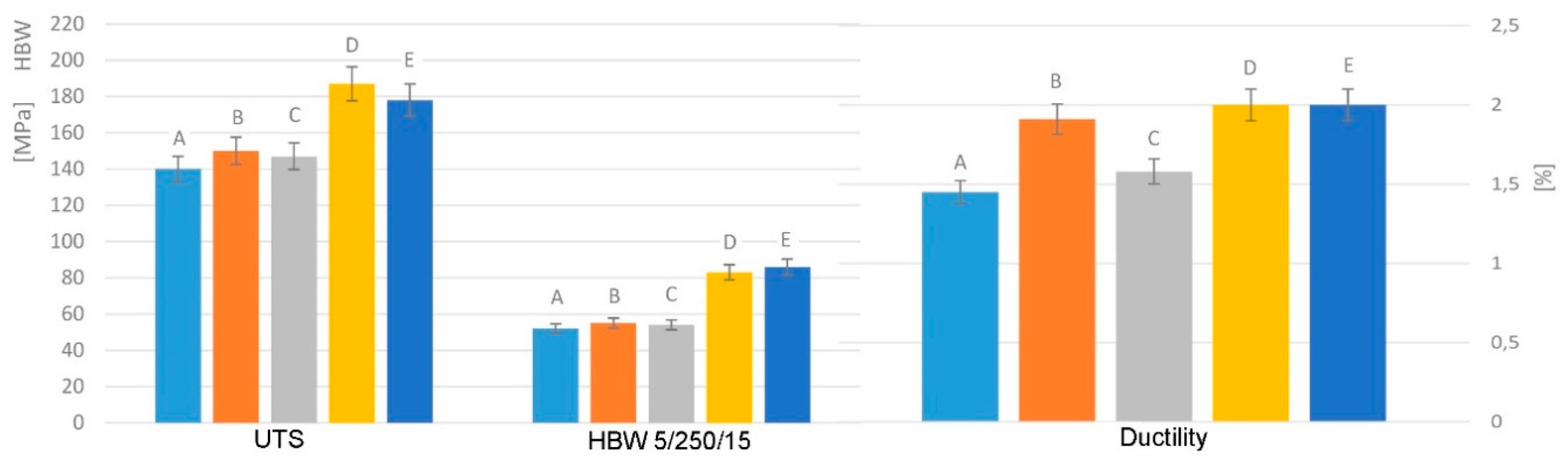
3.1. Mechanical Properties

The results of mechanical properties show increasing or comparable properties with increasing content of Fe in both types of experimental material (Figure 1). The first material type AlSi7Mg0.3 has maximum mechanical properties in state (B) with 0.454 wt. % of Fe (UTS = 150 MPa, HBW = 55, and ductility = 1.91%). The A-series specimens (in the state according to standards) have the lowest mechanical properties (UTS = 141 MPa, HBW = 52, and ductility = 1.45%). The differences of UTS and Brinell hardness are insignificant, because these are about 5–7% in UTS, and 3.5–5.7% in HBW. More important are the differences in ductility of about 9–30%. 30% was present in samples B (with 0.454% of Fe). The above is probably related to a higher content of Si causing finessing of the alpha matrix [5,6].
The second experimental material AlZn10Si8Mg showed a decrease in UTS, a little increase in Brinell hardness and a comparable value of ductility by comparing standards, as well as a higher content of Fe (Figure 1). The increase in Brinell hardness was caused by with a higher amount of hard and brittle Fe-needles phases. The difference was of 5%, therefore these changes in mechanical properties are insignificant. The usage of the material with higher content is not impossible. The influence of the α-matrix, as reported Osório [5], was confirmed. Mechanical properties change of the same experimental materials properties with different content of Fe was just slightly different, because of the α-matrix (finesses and content) being very similar for each material (Figure 2 and Figure 3).
Regarding the possibility of replacing AlSi7Mg0.3 with AlZn10Si8Mg, it we can say that AlZn10Si8Mg has better mechanical properties compared to AlSi7Mg0.3 cast alloy (but this alloy is in not heat-treated state). The ultimate tensile strength was 33% higher, Brinell hardness by 59%, and ductility by about 38% in as cast state of both materials.

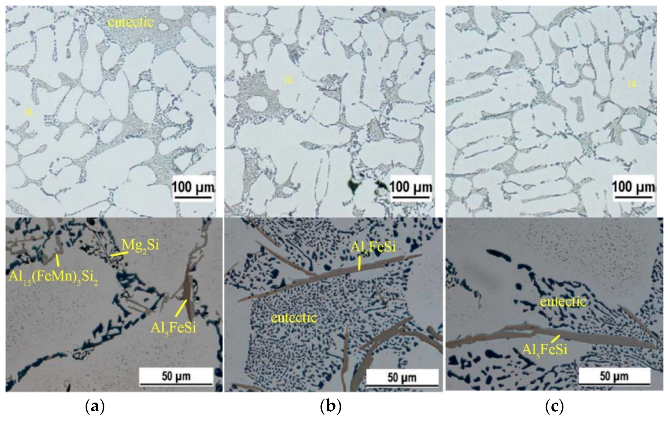
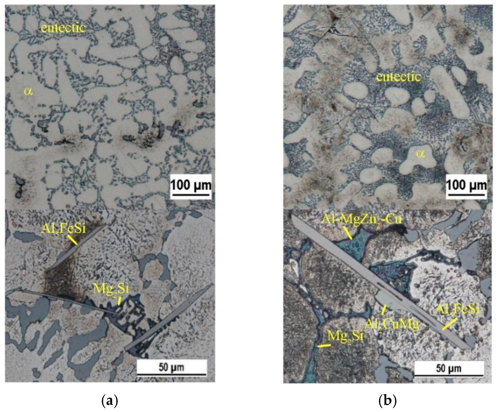
3.2. Microstructure of Experimental Materials

Typical hypoeutectic aluminum–silicon alloys possess two major microstructural components, namely, aluminum matrix and an aluminum-silicon eutectic. The wide variety of intermetallic phases in aluminum alloys occurs because of Al high reactivity, caused by its negative standard potential [9]. Most negative are iron-rich intermetallic phases. In Fe-containing aluminum cast alloys, Fe-rich intermetallic phases are formed, such as β-Al5FeSi; Al9FeSi2, Al3FeSi2, Al4FeSi2, α-Al15(FeMn)3Si2, Al8Fe2Si, Al19Fe4MnSi, Al12MnSi2, Al12Fe3Si, π-Al8Mg3FeSi6, and Al5Si6Mg8Fe2. From these phases identified in Al-Si base alloys, the α-Al15FeMn3Si2 and β-Al5FeSi phases are more important [12,13,14,15]. The Chinese script morphology of the α-iron phase occurs during eutectic solidification. The iron phase can also appear in the form of polyhedrons if it solidifies as a primary phase. The β-phases crystallize as thin plates looking like needles in their cross section. This phase is mostly associated with iron levels greater than 1 wt. %. From electrochemical point of view, the β-Al5FeSi phase is nobler than the matrix in aqueous media, making the alloy system highly susceptible to localized corrosion. The harmful effect of the β-iron phase can be neutralized by rapid solidification; addition of neutralizers such as Mn, Co., Cr, Ni, Sr, K, and Be can change the morphology of the phases or enhance the precipitation of Fe-rich particles, which are less harmful than needles; melt superheat; strontium modification and non-equilibrium solution heat treatment [1,12,13,14,27,28]. Observation of the basic microstructure of all experimental materials showed that it consists of α-phase dendrites, eutectic (a mechanical mixture of α-phase and eutectic silicon) and different intermetallic phases (Figure 2 and Figure 3).
The α-matrix precipitates from the liquid as a primary phase in the form of dendrites, and it nominally comprises of Al and Si in AlSi7Mg0.3 cast alloy. The size of dendrites (fineness and content) is similar for each state of our experimental materials, but the SDAS is slightly different. Si-particles are like small-poorly rounded grains. However, thickened grains were observed on the periphery of α-phase dendrites (Figure 2). Intermetallic phases in the microstructure of the experimental materials were: Fe-rich intermetallic phases in needles form: Al5FeSi, Fe-rich intermetallic phases in the form of skeleton or Chinese script: Al15(FeMg)2Si2 and Mg-rich intermetallic phases: Mg2Si. Studying the microstructure confirmed formation of Fe-rich intermetallic phases mostly in form of skeleton-like as needles in alloy A (chemical composition according to standards—0.123 wt. % of Fe). Needle, iron-rich intermetallic phases are smallest (alloy A) compared to an increased Fe content (alloys B and C). The increasing amount of Fe leads to formation of larger Fe-needles intermetallic phases (Figure 2) and the amount of these phases’ increases as well. The increasing content of Fe leads to formation of, especially, iron-rich phases in form of needles, then it in forms into skeleton-like shapes. Skeleton-like shapes were not observed in alloys B and C. These findings correlate with research work of authors [12,13,14]. The authors confirmed that the higher the iron content, the longer and wider the needles. The Mg-rich phases were observed in a smaller volume in materials A and B compared to alloy A.
The microstructure of AlZn10Si8Mg cast alloy consists of α-phase, eutectic (dark gray Si crystals in α-phase) and various types of intermetallic phases (Chinese script-Mg2Si, oval round-like particles Al2CuMg, Fe-needles-Al5FeSi, particles of AlFeMnSiNi, and ternary eutectic Al-MgZn2-Cu). (Figure 3) [25,26]. The α-matrix precipitates from the liquid as the primary phase in the form of dendrites and nominally comprises of Al and Zn. The size of dendrites (fineness and content) is similar for both states of the experimental material. Si-particles, in the form of small, poorly rounded, thickened grains were observed on the periphery of α-phase dendrites (Figure 3). Fe-containing intermetallics, such as Al5FeSi phases, are formed especially between the α-dendrites. Studies confirmed that with increasing Fe content grows the amount and length of Fe-rich needle phases in the experimental material AlSi7Mg0.3. Since this alloy, despite its high zinc content, belongs to the typical Al-Si alloys, it could be used as replacement for AlSiMg alloy applications, because it has a similar microstructure to hypoeutectic Al-Si alloys [24,25,26].

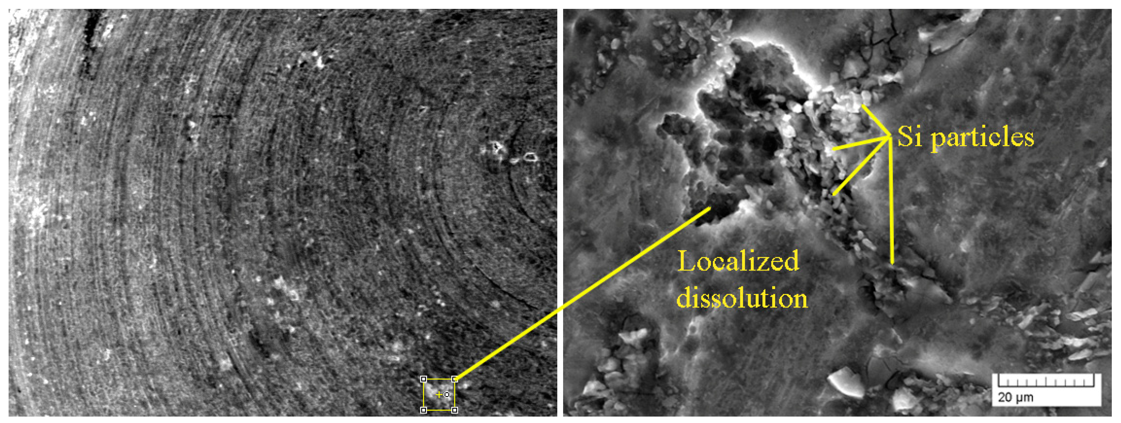
3.3. Corrosion Behavior

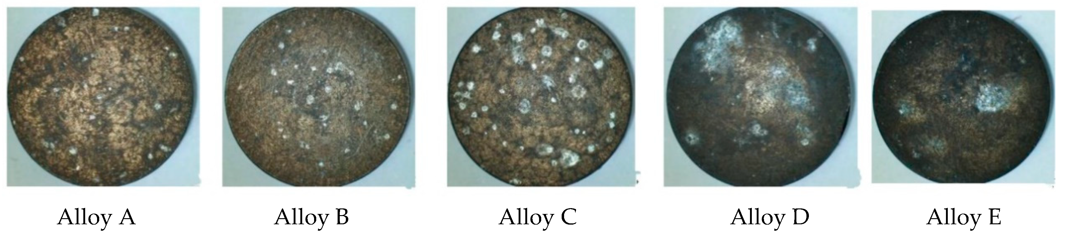
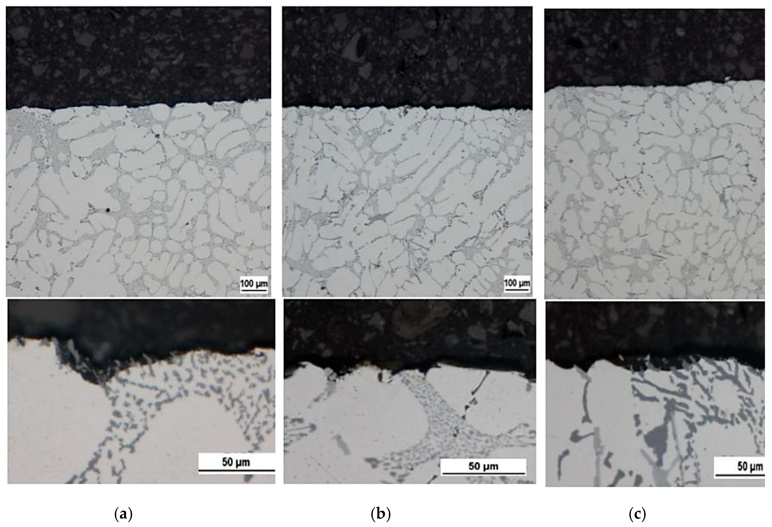
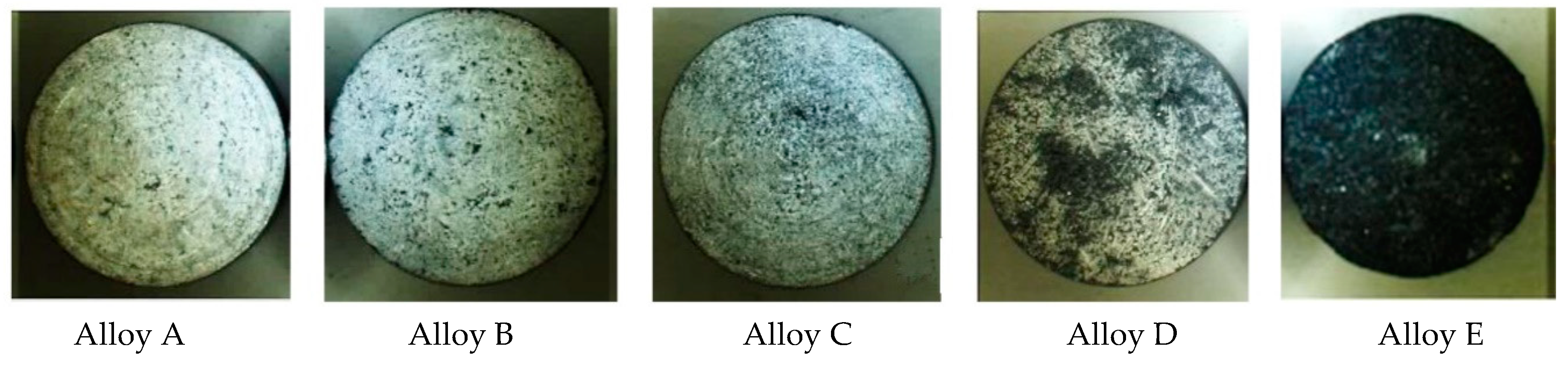
3.3.1. Exposure Test

The specimens of the experimental Al-alloys were immersed in the 3.5 wt. % NaCl solution at 20 °C for three weeks. Corrosion attack was evaluated visually, by light and electron microscopy. By first visual evaluation (Figure 4), differences in corrosion characteristics of the tested alloys were apparent. Pitting corrosion was observed preferentially in alloy AlSi7Mg0.3. The density and scale of corrosion pits grew with the Fe content. The effect of Fe on pitting corrosion of Al-alloys was confirmed earlier by Samuel [13] and Aziz [29]. Mingo et al. [30] and Arrabal et al. [4] mentioned in their work that in A356 (AlSi7Mg0.3) alloy corrosion initiates at the interface between the α-Al matrix and the Fe-rich intermetallic as a result of microgalvanic corrosion processes. Specimens of the AlZn10Si8Mg alloy were attacked by general irregular corrosion and their surface was covered by grey corrosion products. This correlates with the results by Khireche [31] stating that the impedance measurements and the microscopic observations confirmed the great activity of Al-Zn and Al-Zn-Sn compared to pure Al to corrosion. The segregation at the grain boundaries leads to intergranular corrosion. The assessment of the AlSi7Mg0.3(alloy B) surfaces after exposure test by using scanning electron microscopy shows that on surface there are places with localized corrosion pits (Figure 5). SEM observation of the AlZn10Si8Mg alloys was not sufficient.
Corrosion pits start nearby cathodic Si particles, where the protective layer is diminished and grain boundaries are weaker as well. This results in an agreement with experimental results of Arrabal [4], Mingo [30], Davis [32], and Osório [33]. We suppose that the Fe cathodic particles can have a similar effect and can promote a higher density of corrosion pits in specimens with a bigger content of Fe. According to the authors of [33], Si particles disseminated throughout the Al-rich phase. Because of the different growth mechanisms of each phase that was mentioned, their boundaries are not perfectly conformed, but are rather subjected to a certain deformation at atomic level, mainly in the phase side of the interface. It seems that these regions, due to their massive localized deformation, could be more susceptible to corrosion than a phase region that are not too close to the Si particles (Figure 6 and Figure 7).
In some places of researched specimens, this pit dissolution was combined with inter-granular corrosion (Figure 6). A similar attack was observed by Gharavi [34] in their work. The EDX analysis also showed that corrosion products identified by a higher concentration of oxygen are localized in around Si particles. Near to the Fe particles, a slight accumulation of corrosion products was also observed (Figure 6).
Metallographic analyses of the AlSi7Mg0.3 alloy confirmed (Figure 7) that in corrosion pits the matrix is dissolved and the Si particles are resistant to the chloride solution. The beginning of intergranular corrosion was observed only on the specimen surface. With the higher Fe content, the matrix major amount of cathodic needles forms in the Al-alloy. This may create more places for corrosion on the surface. The above was agreed by visual detection (Figure 7).
The specimens of AlZn10Si8Mg cast alloys featured intensive inter-granular corrosion (Figure 8), which can be expected in this type of Al-alloy [35]. Figures demonstrated a similar effect as the one described by Tahamtan [8]. It shows galvanic corrosion between silicon particles and the α-matrix. The results of exposure tests show that the susceptibility to inter-granular corrosion increased by higher Fe content.

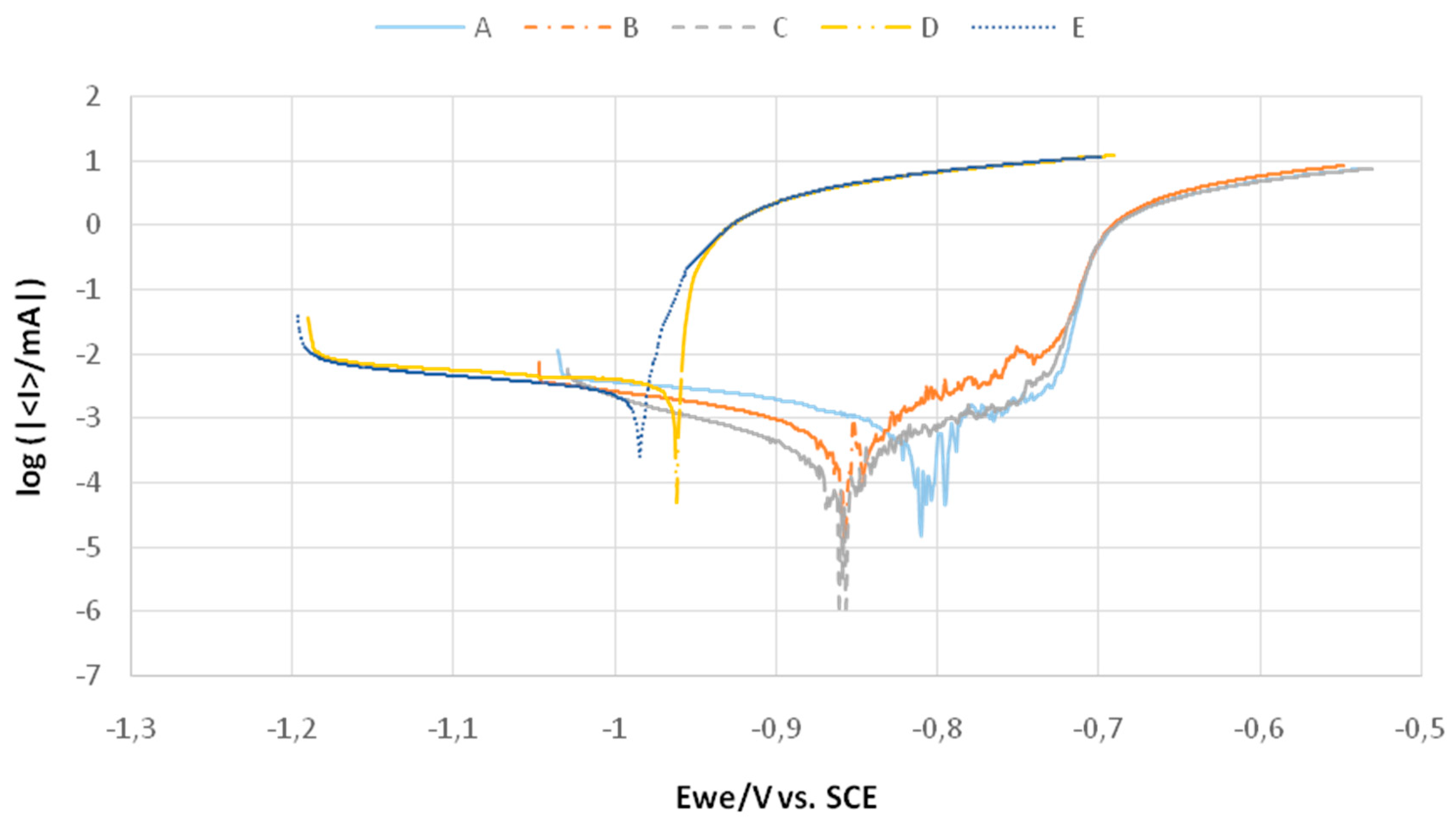
3.3.2. Potentiodynamic Test

The corrosion characteristics achieved by potentiodynamic measurement test made in chloride solution reflect the Fe content in the AlSi7Mg0.3 alloy. The corrosion potential Ecorr of all AlSi7Mg0.3 alloy with a differing Fe-drop content very slightly differ with an increasing Fe content. However, the differences are negligible (Table 2). The decrease in the corrosion rate is very well comparable in Figure 9. The Fe up to 0.655 wt. % content shows that the corrosion rate decreased almost by a half. It is interesting that the thermodynamic stability presented by Ecorr decreased with the Fe content, but kinetics of the corrosion process expressed by the corrosion rate was retained.
In the AlZn10Si8Mg alloy with a higher Fe Ecorr content, the corrosion rate can be considered equivalent. In Figure 9 we can compare the corrosion resistivity of the alloys AlSi7Mg0.3 and AlZn10Si8Mg. The alloys (A, C-D, E) with similar Fe contents, but with higher contents of Zn have a different corrosion behavior. The Zn content decreases the corrosion resistance of Al cast alloys, but negative influences elevated contents of Fe were not recorded.

3.3.3. Audi Test

In practice, the Audi test is used to test corrosion behavior of Al alloys. The reason of its application in this work was to compare the results of this test with the ones usually applied in research works. The Audi test was carried out in an acid chloride solution (1 dm3 H2O + 20 g NaCl + 0.1 dm3 25% HCl) for 2 h. Characteristics of the corrosion attack are documented in Figure 10. In or to determine the corrosion rates, experimental alloys were rinsed after testing in distilled water and dried, weighted before and after testing. The corrosion rate was calculated from weight losses (Table 3).
Visual evaluation is shown in Figure 10, and no corrosion products are seen on the surface of AlSi7Mg0.3 alloy specimens with differing Fe content. Corrosion pits were only observed, especially on the specimen with a medium Fe content. Osório [5,6] in his work demonstrated that an increased Si content provoked a decreased corrosion resistance. This can be an explanation for the difference between specimens B and C. The highest Si content was included in the experimental material labeled B—one of the AlSi7Mg0.3 cast alloys (7.34%—Table 1).
Specimens of AlZn10Si8Mg were covered by grey corrosion products. The corrosion products on the AlZn10Si8Mg alloy with a lower Fe content were not been continuous when compared to the ones on the surface of the sample with a higher Fe content. The corrosion rate calculated from weight losses was nearly four times higher.
Under the above conditions, AlSi7Mg0.3 alloys with varying Fe content were much more resistant to corrosion.

4. Conclusions

According to the experiments and analysis performed, we can conclude that:
  • Various chemical compositions greatly influence the studied properties of the tested aluminum alloys.
  • In terms of the effect of higher Fe content, the mechanical properties of AlZn10Si8Mg and AlSi7Mg0.3 cast alloys are not significantly influenced by it. The presence of hard and brittle Fe-needle phases leads to slightly improved mechanical properties. Therefore, the use of such materials does not significantly influence the mechanical properties of resulting alloys.
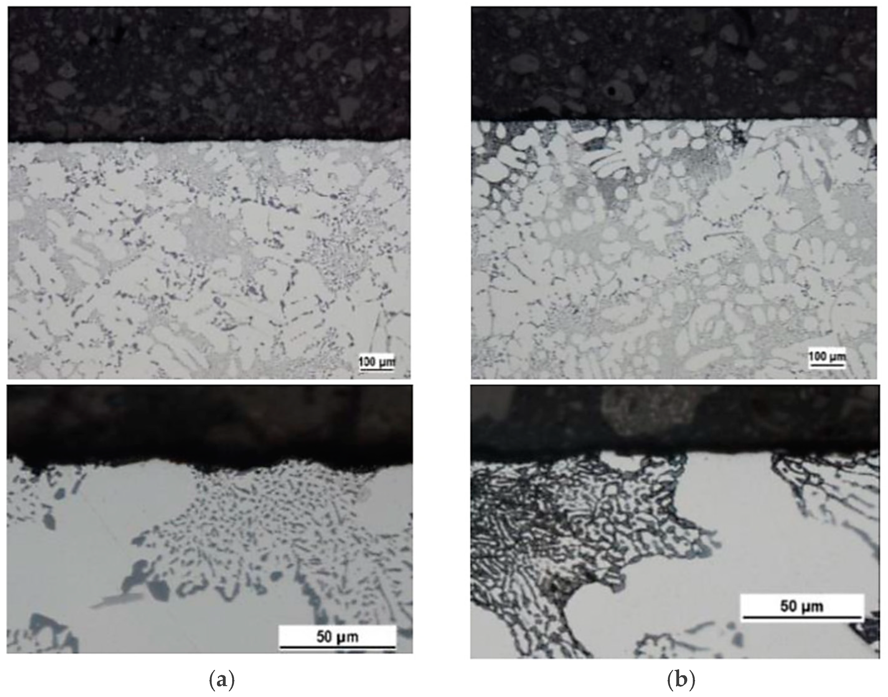
  • The microstructure of both types of experimental materials is typically hypoeutectic, involving an α-matrix, eutectic and intermetallic phases. The α-phase’s finesses and content were similar in the same experimental material. The silicon present is in the form of small grains of poorly rounded, thickened grains that were observed on the periphery of dendrites α-phase. Out of the intermetallic phases were in microstructure of AlSi7Mg0.3 cast alloys observed: Al5FeSi, Al15(FeMg)2Si2 and Mg2Si. The Mg2Si, Al2CuMg, Al5FeSi, AlFeMnSiNi and Al-MgZn2-Cu in AlZn10Si8Mg cast alloy. In both experimental materials were observed increase lengths and amounts of Fe-needle phases as a reaction to increased Fe content in the microstructure.
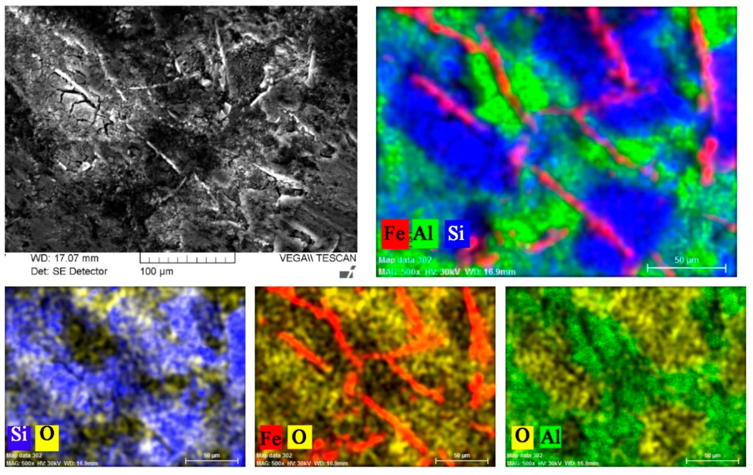
  • Worse corrosion properties were documented in case of AlZn10Si8Mg cast alloys, compared to experimental AlSi7Mg0.3 by all carried out experiments. During their exposure and Audi tests, it showed that higher Fe contents decrease corrosion resistance of experimental materials, but with regard to Si content. Based on the results of potentiodynamic a test was found that higher Fe amounts in AlSi7Mg0.3 casts alloys decelerate corrosion kinetic. These results correlate with Osório’s work [33]. All applied tests showed better corrosion resistance in AlSi7Mg0.3 cast alloys. But it was also found that the above depends not only on the Fe content, but also on the proportion of Fe and Si in the Al alloys as reported by Osório [6] in his work.

Author Contributions

Conceptualization, L.K., T.L. and E.T.; Methodology, L.K., T.L. and E.T.; Software, L.K., D.K. and E.S.; Validation, L.K., T.L., E.T. and Z.Z.; Formal Analysis, L.K., T.L., D.K. and E.S.; Investigation, L.K., D.K. and E.S.; Resources, L.K., T.L. and E.T.; Data Curation, L.K., T.L. and D.K.; Writing-Original Draft Preparation, L.K. and T.L.; Writing-Review & Editing, L.K., T.L., D.K. and E.T.; Visualization, L.K., T.L. and E.T.

Funding

This research was funded by Scientific Grant Agency of Ministry of Education of Slovak republic VEGA grants number [No1/0533/15] and [No1/0029/18].

Conflicts of Interest

The authors declare no conflicts of interest.

References

  1. Hirsch, J.; Al-Samman, T. Superior light metals by texture engineering: Optimized aluminum and magnesium alloys for automotive applications. Acta Mater. 2013, 61, 818–843. [Google Scholar] [CrossRef]
  2. Rosso, M.; Peter, I.; Castella, C.; Molina, R. Properties of AlZn10Si8Mg alloys for high performances application. In Light Metals; Springer: Cham, Switzerland, 2014; pp. 213–218. [Google Scholar]
  3. Oztürk, I.; Agaoglu, G.H.; Erzi, E.; Dispinar, D.; Orhan, G. Effects of strontium addition on the microstructure and corrosion behavior of A356 aluminum alloy. J. Alloys Compd. 2018, 763, 384–391. [Google Scholar] [CrossRef]
  4. Arrabal, R.; Mingo, B.; Pardo, A.; Mohedano, M.; Matykina, E.; Rodriguez, I. Pitting corrosion of rheocast A356 aluminum alloy in 3.5 wt. % NaCl solution. Corros. Sci. 2013, 73, 342–355. [Google Scholar] [CrossRef]
  5. Osório, W.R.; Garcia, L.R.; Goulart, P.R.; Garcia, A. Effects of eutectic modification and T4 heat treatment on mechanical properties and corrosion resistance of an Al–9 wt. % Si casting alloy. Mater. Chem. Phys. 2007, 106, 343–349. [Google Scholar] [CrossRef]
  6. Osório, W.R.; Goulart, P.R.; Garcia, A. Effect of silicon content on microstructure and electrochemical behavior of hypoeutectic Al–Si alloys. Mater. Lett. 2008, 62, 365–369. [Google Scholar] [CrossRef]
  7. Cecchel, S.; Cornacchia, G.; Gelfi, M. Corrosion behavior of primary and secondary AlSi high pressure die casting alloys. Mater. Corros. 2017, 68, 961–969. [Google Scholar] [CrossRef]
  8. Tahamtan, S.; Boostani, A.F. Evaluation of pitting corrosion of thixoformed A356 alloy using a simulation model. Trans. Nonferrous Met. Soc. China 2010, 20, 1702–1706. [Google Scholar] [CrossRef]
  9. Ye, H. An Overview of the development of Al-Si-Alloy based material for engine applications. J. Mater. Eng. Perform. 2003, 12, 288–297. [Google Scholar] [CrossRef]
  10. Chena, C.L.; West, G.; Thomsonb, R.C. Characterisation of intermetallic phases in multicomponent Al-Si casting alloys for engineering applications. Mater. Sci. Forum 2006, 519–521, 359–364. [Google Scholar] [CrossRef]
  11. Donatus, U.; Thompson, G.E.; Omotoyinbo, J.A.; Alaneme, K.K.; Aribo, S.; Agbabiaka, O.G. Corrosion pathways in aluminum alloys. Trans. Nonferrous Met. Soc. China 2017, 27, 55–62. [Google Scholar] [CrossRef]
  12. Tupaj, M.; Orłowicz, A.W.; Mróz, M.; Trytek, A.; Markowska, O. The effect of cooling rate on properties of intermetallic phase in a complex Al-Si alloy. Arch. Foundry Eng. 2016, 16, 125–128. [Google Scholar] [CrossRef]
  13. Samuel, A.M.; Samuel, F.H.; Doty, H.W.; Valtierra, S. Beta Al5FeSi phase platelets-porosity formation relationship in A319.2 type alloys. Inter. J. Met. Cast. 2018, 12, 55–70. [Google Scholar] [CrossRef]
  14. Khalifa, W.; Samuel, F.H.; Gruzleski, J.E. Iron intermetallic phases in the Al corner of the Al–Si–Fe system. Metall. Mater. Trans. A 2003, A34, 807–825. [Google Scholar] [CrossRef]
  15. Kral, M. A crystallographic identification of intermetallic phases in Al-Si alloys. Mater. Lett. 2005, 59, 1–6. [Google Scholar] [CrossRef]
  16. Shabestari, S.G. The effect of iron and manganese on the formation of intermetallic compounds in aluminum–silicon alloys. Mater. Sci. Eng. 2004, A383, 289–298. [Google Scholar] [CrossRef]
  17. Yasakau, K.A.; Zheludkevich, M.L.; Lamaka, S.V.; Ferreira, M.G.S. Role of intermetallic phases in localized corrosion of AA5083. Electrochim. Acta 2007, 52, 7651–7659. [Google Scholar] [CrossRef]
  18. Taylor, J.A.; Schaffer, G.B.; Stjohn, D.H. The role of iron in the formation of porosity in Al-Si-Cu–based casting alloys: Part II. a phase-diagram approach. Metall. Mater. Trans. A 1999, 30A, 1651–1655. [Google Scholar] [CrossRef]
  19. Závodská, D.; Tillová, E.; Guagliano, M.; Chalupová, M.; Kucharikova, L. Effect of porosity on the fatigue behavior of AlZn10Si8Mg casting alloys in a high cycle region. Procedia Eng. 2017, 192, 988–993. [Google Scholar] [CrossRef]
  20. Kučera, V.; Vojtěch, D. Influence of heat treatment on corrosion behavior and mechanical properties of the AA 7075 alloy. Manuf. Technol. 2017, 17, 747–752. [Google Scholar]
  21. Linder, J. The influence of surrounding environment on the fatigue properties for a high pressure die cast AlSi9Cu3 alloy. Fatigue Fract. Eng. Mater. Struct. 2007, 30, 759–765. [Google Scholar] [CrossRef]
  22. Cardinale, A.M.; Macciò, S.; Luciano, G.; Canepa, E.; Traverso, P. Thermal and corrosion behavior of as cast Al-Si alloys with rare earth elements. J. Alloys Compd. 2017, 695, 2180–2189. [Google Scholar] [CrossRef]
  23. Camicia, G.; Timelli, G. Grain refinement of gravity die cast secondary AlSi7Cu3Mg alloys for automotive cylinder heads. Trans. Nonferrous Met. Soc. China 2016, 26, 1211–1221. [Google Scholar] [CrossRef]
  24. Vicen, M.; Fabian, P.; Tillová, E. Self-hardening AlZn10Si8Mg aluminum alloy as an alternative replacement for AlSi7Mg0.3 aluminum alloy. Arch. Foundry Eng. 2017, 17, 139–142. [Google Scholar] [CrossRef]
  25. Ďuriníková, E.; Tillová, E.; Chalupová, M. Phase and structure characteristics of recycled AlZn10Si8Mg cast alloy. Manuf. Technol. 2011, 11, 11–17. [Google Scholar]
  26. Tillová, E.; Chalupová, M.; Kuchariková, L.; Závodská, D.; Belan, J.; Vaško, A. Use of microscopy in the study of self-hardening al-alloy for automotive application. Manuf. Technol. 2016, 16/5, 1174–1179. [Google Scholar]
  27. Moustafa, M.A. Effect of iron content on the formation of β-Al5FeSi and porosity in Al–Si eutectic alloys. J. Mater. Process. Technol. 2009, 209, 605–610. [Google Scholar] [CrossRef]
  28. Ferraro, S.; Timelli, G. Influence of sludge particles on the tensile properties of die-cast secondary aluminum alloys. Metall. Mater. Trans. B 2015, 46B, 1022–1034. [Google Scholar] [CrossRef]
  29. Aziz, P.M.; Godard, H.P. Pitting corrosion characteristics of aluminum—The influence of iron and silicon. Corrosion 1954, 10, 269–272. [Google Scholar] [CrossRef]
  30. Mingo, B.; Arrabal, R.; Pardo, A.; Matykina, E.; Skeldon, P. 3D study of intermetallics and their effect on the corrosion morphology of rheocast aluminum alloy. Mater. Charact. 2016, 112, 122–128. [Google Scholar] [CrossRef]
  31. Khireche, S.; Boughrara, D.; Kadri, A.; Hamadou, L.; Benbrahim, N. Corrosion mechanism of Al, Al–Zn and Al–Zn–Sn alloys in 3 wt. % NaCl solution. Corros. Sci. 2014, 87, 504–516. [Google Scholar] [CrossRef]
  32. Davis, J.R. ASM Specialty Handbook: Aluminum and Aluminum Alloys; ASM International: Metals Park, OH, USA, 1993; pp. 579–622. [Google Scholar]
  33. Osório, W.R.; Goulart, P.R.; Santos, G.A.; Neto, C.M.; Garcia, A. Effect of dendritic arm spacing on mechanical properties and corrosion resistance of Al 9 Wt Pct Si and Zn 27 Wt Pct Al Alloys. Metall. Mater. Trans. A 2006, 37A, 2525–2538. [Google Scholar] [CrossRef]
  34. Gharavi, F.; Matori, K.A.; Yunus, R.; Othman, N.K. Corrosion behavior of friction stir welded lap joints of AA6061-T6 aluminum alloy. Mater. Res. 2014, 17, 672–681. [Google Scholar] [CrossRef] [Green Version]
  35. Knight, S.P.; Salagaras, M.; Trueman, A.R. The study of intergranular corrosion in aircraft aluminum alloys using X-ray tomography. Corros. Sci. 2011, 53, 727–734. [Google Scholar] [CrossRef]
Figure 1. Mechanical properties of experimental materials.
Metals 08 00581 g001
Figure 2. Microstructure of AlSi7Mg0.3 cast alloys, etch. MA. (a) alloy A with 0.123 wt. % Fe; (b) alloy B with 0.454 wt. % Fe; (c) alloy C with 0.655 wt. % Fe.
Metals 08 00581 g002
Figure 3. Microstructure of AlZn10Si8Mg cast alloys, etch. Dix-Keller. (a) alloy D with 0.150 wt. % Fe; (b) alloy E with 0.559 wt. % Fe.
Metals 08 00581 g003
Figure 4. Corrosion characteristics of the tested alloys after exposure test.
Metals 08 00581 g004
Figure 5. SEM observation of a corrosion attack on samples of alloy B after testing.
Metals 08 00581 g005
Figure 6. Energy dispersive X-rays (EDX) analysis of corrosion localization of alloy B after testing.
Metals 08 00581 g006
Figure 7. Corrosion attack of AlSi7Mg0.3 cast alloys, etch. MA. (a) alloy A with 0.123% Fe; (b) alloy B with 0.454% Fe; (c) alloy C with 0.655% Fe.
Metals 08 00581 g007
Figure 8. Corrosion attack of AlZn10Si8Mg cast alloys, etch. Dix-Keller. (a) alloy D with 0.150% Fe; (b) alloy E with 0.559% Fe.
Metals 08 00581 g008
Figure 9. Potentiodynamic polarization curves of the experimental materials in 0.1 M NaCl solution.
Metals 08 00581 g009
Figure 10. Corrosion characteristics of the tested alloys after the Audi test.
Metals 08 00581 g010
Table 1. Chemical composition measured using arc spark spectroscopy, wt. %.
AlloySiFeCuMnMgZnTiNaAlOther
A7.0280.1230.0130.0090.3540.0360.1230.00292.253balance
B7.340.4540.0210.0090.3020.020.1180.00491.673balance
C7.3150.6550.030.010.2920.0280.120.00591.486balance
D8.7030.1500.0080.0130.38110.0010.050.00280.64balance
E8.8310.5590.0080.0190.3199.3350.0490.00280.828balance
Table 2. Corrosion characteristics of the tested Al-alloys.
AlloyEcorr (mV)icorr (µA/cm2)rcorr (mm/year)
A−824.333 ±340.85367 ±0.02590.022 ±0.001
B−833.333 ±320.821 ±0.01370.01333 ±0.001
C−850.666 ±110.49133 ±00.1610.008067 ±0.001
D−984 ±232.457 ±0.05670.04 ±0.003
E−1022.33 ±382.49133 ±0.01920.04 ±0.002
Table 3. Corrosion rate of the tested alloys after Audi test.
AlloyCorrosion rate (g/m2)
A0.00768
B0.175957
C0.132133
D0.23014
E0.840229

