Article

Effect on Blank Holding Force on Blank Deformation at Direct and Indirect Hot Deep Drawings of Boron Steel Sheets

1
Department of Computer Software Engineering, Changshin University, 262 Paryong-ro, Masanhoiwon-gu, Changwon-si, Gyeongsangnam-do 51352, Korea
2
School of Mechanical Engineering, Kyungnam University, 7 Kyungnamdaehak-ro, Masanhappo-gu, Changwon-si, Gyeongsangnam-do 51767, Korea
3
School of Mechanical Engineering, Pusan National University, San 30 Chang Jun-dong, Geum Jung-Gu, Busan 46241, Korea
*
Author to whom correspondence should be addressed.
Metals 2018, 8(8), 574; https://doi.org/10.3390/met8080574
Submission received: 6 July 2018 / Revised: 20 July 2018 / Accepted: 24 July 2018 / Published: 25 July 2018
(This article belongs to the Special Issue Modelling and Simulation of Sheet Metal Forming Processes)

Abstract

:
This study involves performing direct and indirect hot press forming on ultra-high-strength steel (UHSS) boron steel sheets to determine formability. The indirect hot press process is performed as a cold deep drawing process, while the direct hot press process is performed as a hot deep drawing process. The initial blank temperature and the blank holding force are set as parameters to evaluate the performance of the direct and indirect deep drawing processes. The values of punch load and forming depth curve were obtained in the experiment. In addition, the hardness and microstructure of the boron steel sheets are examined to evaluate the mechanical properties of the material. The forming depth, maximum punch load, thickness, and thinning rate according to blank holding force were examined. The result shows that a larger blank holding force has a more significant effect on the variation of the thickness and thinning rate of the samples during the drawing process. Furthermore, the thinning rate of the deep drawing part in with and without fracture boundary was respectively examined.

1. Introduction

Boron steel currently represents the ultra-high-strength steel (UHSS) applied in the automotive industry because of the demand for higher passive safety and weight reduction. However, ultra standard high-strength steels, like boron steel, are difficult to manufacture with cold forming because of disadvantages such as large forming forces, the difficulty of forming complex components, and the occurrence of serious springback at room temperature [1,2]. Therefore, requirements regarding complexity and accuracy increase.
Hot press forming is used widely in the automotive industry. Hot forming can vastly improve the tensile strength of the components. Nowadays, hot press forming at an elevated temperature makes it possible to produce high strength. Hot stamping is not only an innovative technique that is used to produce UHSS components like side impact and bumper beams, but it also reduces the springback under high-temperature forming and achieve good formability. The low springback attributed to in-die cooling gives boron steel an unparalleled edge in dimension control and subsequent assembly process [3,4]. Naderi et al. presented hot stamping as a non-isothermal, high-temperature forming process, in which complex ultra-high-strength parts are produced, with the goal of no springback [5]. Altan studied the formability of boron-alloyed steels at high temperatures of 650 °C to 850 °C [6]. The results showed that the material has excellent formability and can be formed into a complex shape in a single stroke. He also studied the tensile strength and microstructure change during hot stamping. Xing et al. set up a material model under the hot stamping condition of quenchable steel, based on the experimental data for the mechanical and physical properties [7].
In addition to the parameters of conventional cold press forming, such as the blank holding force, punch velocity, punch and die radii, and friction coefficient, the blank temperature and quenching methods also affect the formability and complicate the hot forming process. So et al. provided information on cold and warm blanks of the quenchable boron steel 22MnB5 [8]. From their experimental research, it can be concluded that higher quality and more economical production can be achieved by adjusting the blanking process parameters for the commonly used ultra-high-strength steel sheet 22MnB5. Nakagawa et al. examined the springback and the deformation behavior in hot stamping of a steel sheet with 0.6 mm thickness [9]. Löbbe and Tekkaya investigated the mechanisms influencing the geometrical and mechanical properties of the products after heat-assisted sheet forming processes [10].
Borsetto et al. investigated the influence of the thermal process parameters on the chemical behavior of the Al-Si layer coating, in terms of the heating temperature, holding time, and cooling rate [11]. Naderi et al. described the hot stamping facilities and methods used in experiments [12]. They studied the effect of a hot stamping process on the microstructural and mechanical properties of boron-alloyed and non-boron-alloyed steels and presented an innovative method to carry out a metallographic analysis by the application of lateral and surface hardness maps. Ryan et al. reported on the hot forming die by which various mechanical properties can be partially obtained through the control of the cooling rate in hot forming [13]. Ouyang et al. proposed a friction coefficient and heat transfer coefficient between die and blank with cold and hot deep drawing processes [14]. The sheet material is boron sheet with Al-Si coating layer. During the hot press forming, coating layer is fractured by bending and heating during hot deep drawing. Moon et al. and Seok et al. proposed the deformation behavior of the coating layer on boron sheet [15,16].
As shown in reported research recently, the comparison study of formability and deformation behavior considering blank holding force in hot deep drawing (direct hot press forming) and cold deep drawing (indirect hot press forming) is limited. Therefore, in this study, the relationship between the forming depth and forming load has been investigated with both deep drawing experimental data for variation of blank holding force.
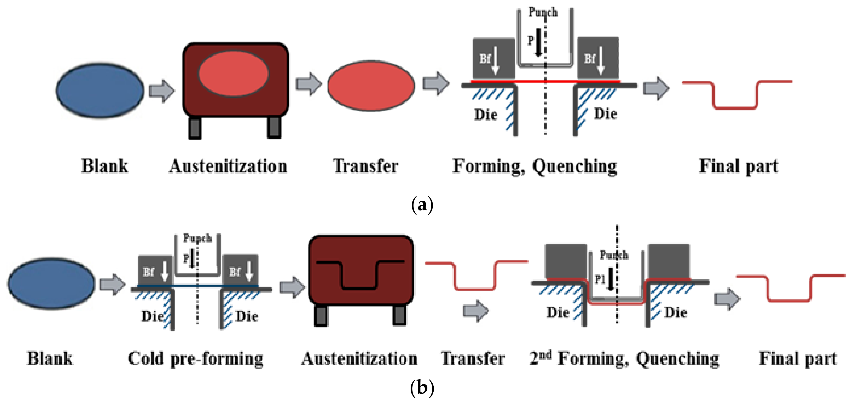
This study, using a boron steel as the blank material, investigated the formability of direct and indirect hot deep drawing under different blank holding forces. Experiments were carried out for direct and indirect hot deep drawing. In direct hot deep drawing, the drawing process carried out with different initial blank temperatures ranged from 850–950 °C, while in indirect hot deep drawing, the blanks were firstly pre-formed in room temperature, and then the cold pre-formed parts were heated to 900 °C and quenched in water. After forming, the forming depth and maximum punch loads for direct and indirect hot deep drawing were examined. Moreover, the thinning rate, microstructure, and hardness at different positions of the drawn part were examined for direct and indirect hot deep drawings.

2. Experimental Methods

2.1. Equipment

The deep drawing equipment used in this study consisted of a 50 ton hydraulic cylinder for moving the forming punch, a 30 ton load cell that was capable of measuring the forming load, a 20 ton hydraulic cylinder that clamped the upper die, and another 5 ton load cell for measuring the clamping force. Additionally, the equipment had a computer which has a linear variable differential transformer (LVDT). When the steel sheet was formed in this equipment, the LVDT measured the punch load according to punch stroke. For the heating, a heat chamber was used that was capable of maintaining 1200 °C of atmosphere temperature. 22MnB5 material with a thickness of 0.6 mm was used in these experiments. The chemical composition of 22MnB5 boron steel is shown in Table 1. Figure 1 shows the engineering stress and engineering strain curve of 22MnB5 boron steel. Yield strength, tensile strength and elongation are 470 MPa, 650 MPa and 27%, respectively.
Figure 2 shows a schematic diagram of the deep drawing die. As shown in Figure 2, there were several cartridge heaters in the upper die, lower die, and punch. Hereby, a constant tool temperature for the dies and punch can be obtained. The blank sheet was Ø75 mm in diameter (D) and 0.6 mm in thickness (t0). The clearance (CL) between the punch and the die was 1.2 mm. Diameter (d) and radius (Rp) of punch was Ø37.6 mm and 4 mm, respectively. Die radius (Rd) was 5 mm. The material and hardness of the die is AISI H13 and 54 HRC, respectively.

2.2. Process

The hot forming process currently exists in two different main processes: the direct hot forming method and the indirect hot forming method. In the direct hot forming process, as shown in Figure 3a, the blanks are austenitized at temperatures between 850 and 950 °C for about 5 min inside a furnace and subsequently transferred to the die set via a transfer unit. Afterwards, the blank is subsequently formed and quenched in the closed tool. Unlike the direct process, indirect hot forming provides for a part to be drawn, unheated, to about 90% to 95% of its final shape in a conventional die, sometimes followed by a partial trimming operation, depending on edge tolerance. The cold pre-formed part is then heated to austenitization temperature in a continuous furnace, sometimes followed by a calibration process (also called 2nd forming process), depending on the complexity and accuracy of the part. The formed part is quenched in the die or water, as shown in Figure 3b. The reason for the additional step is to extend the forming limits for highly complex shapes by heat-treating the cold pre-formed parts. Full martensite transformation in the material causes an increase in the tensile strength of up to 1500 MPa.
Table 2 lists the experiment conditions for direct and indirect hot deep drawing, where Ts represents the initial blank temperature, and Td and Tp represent the die temperature and punch temperature, respectively. In the direct hot deep drawing, samples were separately heated to 850, 900, and 950 °C for 5 min in the furnace to give the sheet material an austenitic microstructure over the entire blank. They were then transferred manually to the heated tooling device used for the drawing process, which were kept at 300 °C. After direct hot drawing, the parts were quenched in the closed die. The total time elapsed before the actual forming process—which included the transfer time and blank holder moving time was approximately 5 s. On the other hand, in indirect hot deep drawing, the blanks were firstly pre-formed in room temperature, which is called the cold pre-forming step, and then the cold pre-formed parts were heated to 900 °C and quenched in water. Both in direct and indirect hot deep drawings, the punch velocity (VP) was fixed at 6 mm/s. Blank holding forces (Bf) were 5 kN, 15 kN, 30 kN, and 90 kN.
After drawing, the properties of drawn cups, such as thinning rate, microstructure, and hardness, were examined. Positions for the measurement of the thinning rate, microstructure and hardness are shown in Figure 4. Position ③ is the middle point between position ② and position ④. For the hardness measurement, Vickers hardness was measured. The load was set to 500 g and measurements were taken five times in total for each specimen. The results were averaged. In order to investigate thinning, the cross section of formed specimens was observed using a digital microscope. The thinning rate shows the amount of change in the thickness after forming compared to the initial thickness. The thinning rate was calculated by Equation (1).
  thinning   rate   =   t 0 t 1 t 0   ×   100  
where, t0 is thickness of the blank and t1 is thickness of formed specimens.

3. Results

Experiments for hot deep drawing with different blank holding forces and initial blank temperatures were carried out. It was observed from the experiments that fracture started to occur at the time that the punch load reached close to the maximum value. 
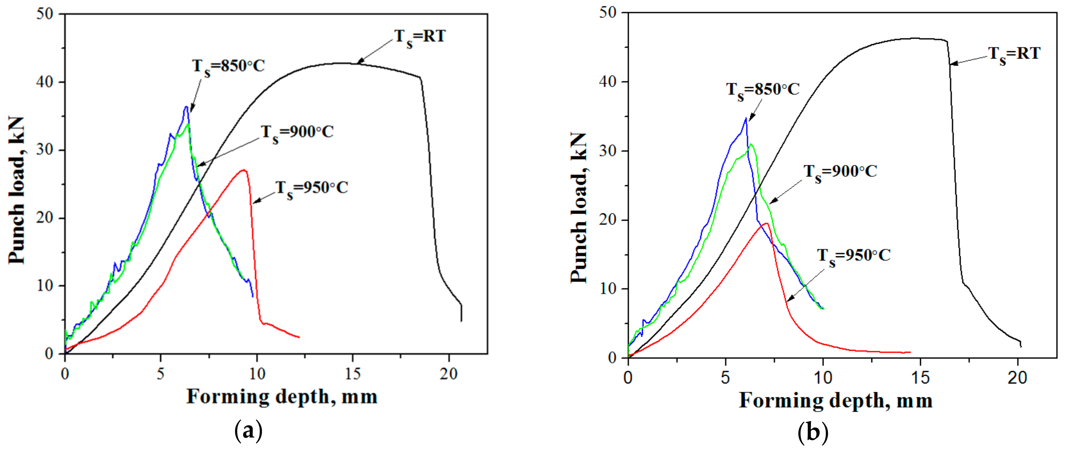
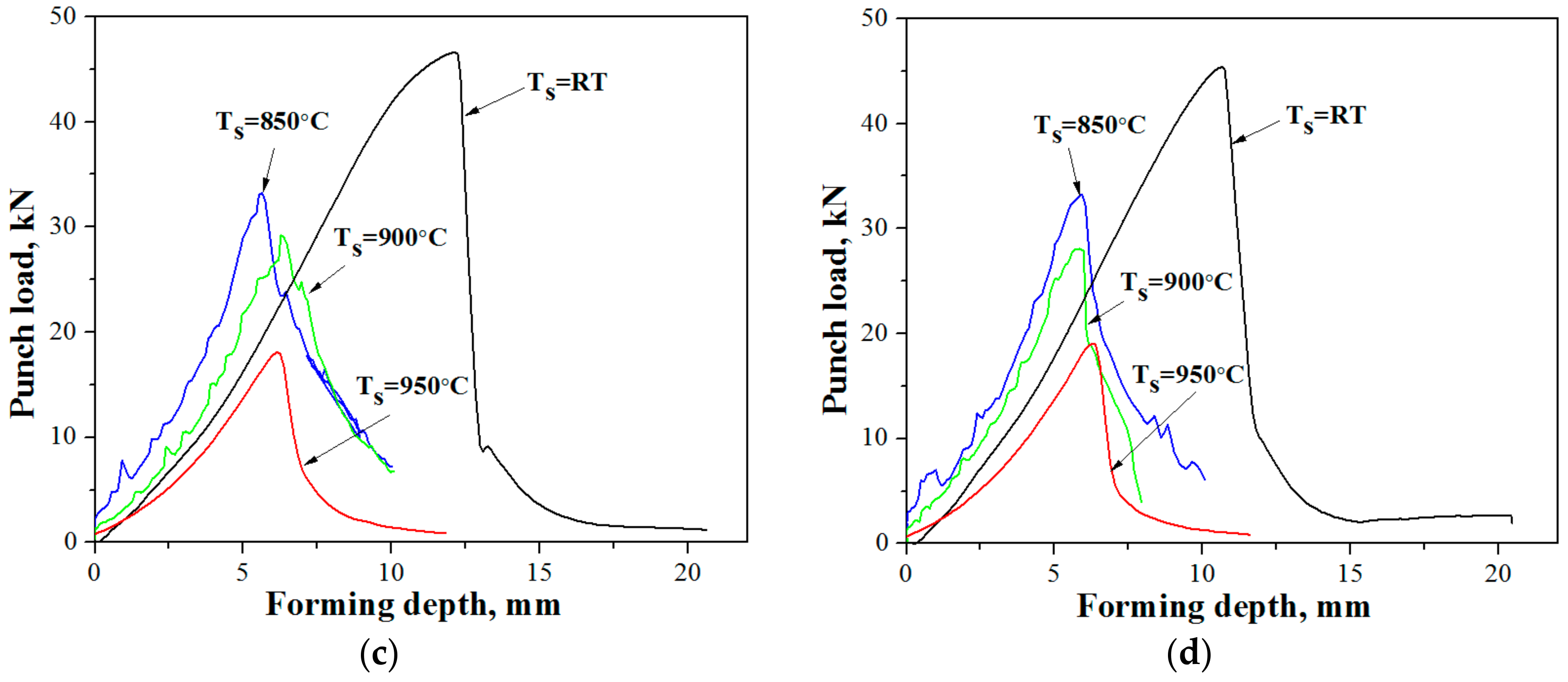
Figure 5 shows the relationship between the punch load and the forming depth for cold pre-deep drawing and direct hot deep drawing at different values of blank holding forces. As shown in Figure 5a, when blank holding force was 5 kN, the forming depth was 18 mm in cold pre-deep drawing. In direct hot deep drawing, the forming depth was 7 mm when blank temperatures were 950 °C, decreasing to 5 mm as blank temperatures decreased to 850 °C. The maximum punch load in cold pre-deep drawing, which was found to be 42 kN, was much higher than that in direct hot deep drawing, which was 26 kN. As can be seen from Figure 5, the maximum punch load and forming depth in cold pre-deep drawing were larger than in direct hot deep drawing. Under the same blank holding forces, as blank temperatures increased from 850 °C to 950 °C, the forming depth increased and required a lower maximum punch load (less than 26 kN for 950 °C). The differences in the forming depth and punch load without any fracture according to blank holding forces are shown in the following figures.
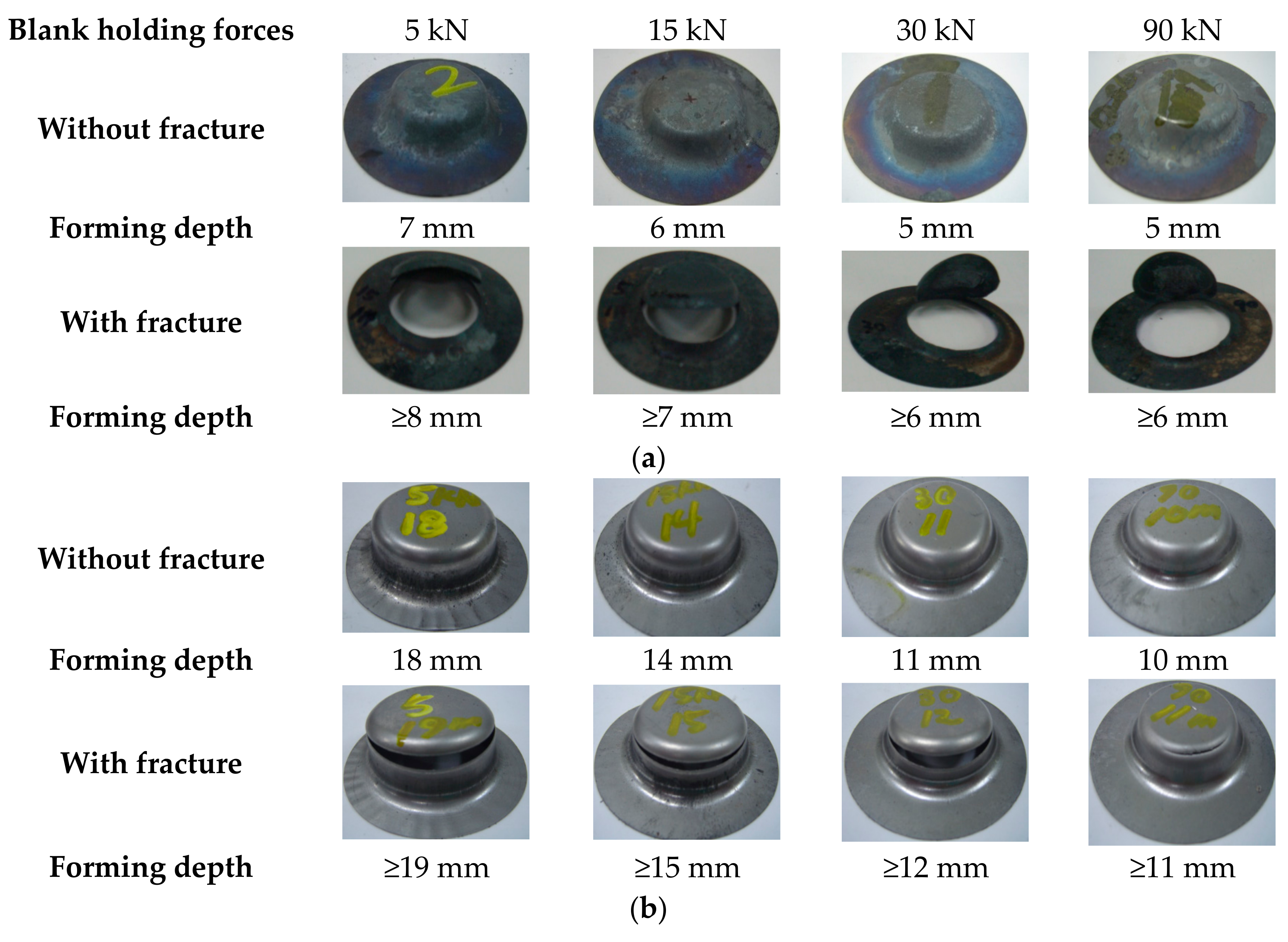
Figure 6 shows the shapes of the drawn cups with fracture and without any fracture at different blank holding forces. As shown in the figures, in both cold pre-deep drawing and in direct hot deep drawing, the fracture started to occur at the wall part of the drawn cups, which agrees with the analyzed results for the thinning rate. In the drawing process, the cup was under a tensile stress state, and the wall thickness decreased quickly. As blank holding forces increased, a fracture occurred more easily, and a lower forming depth was obtained. Further experiments need to be executed under different lubricant conditions and blank holding forces for cold pre-deep drawing and in direct hot deep drawing. This could also reduce the manufacturing cost by determining the optimal lubricant and improving the formability.
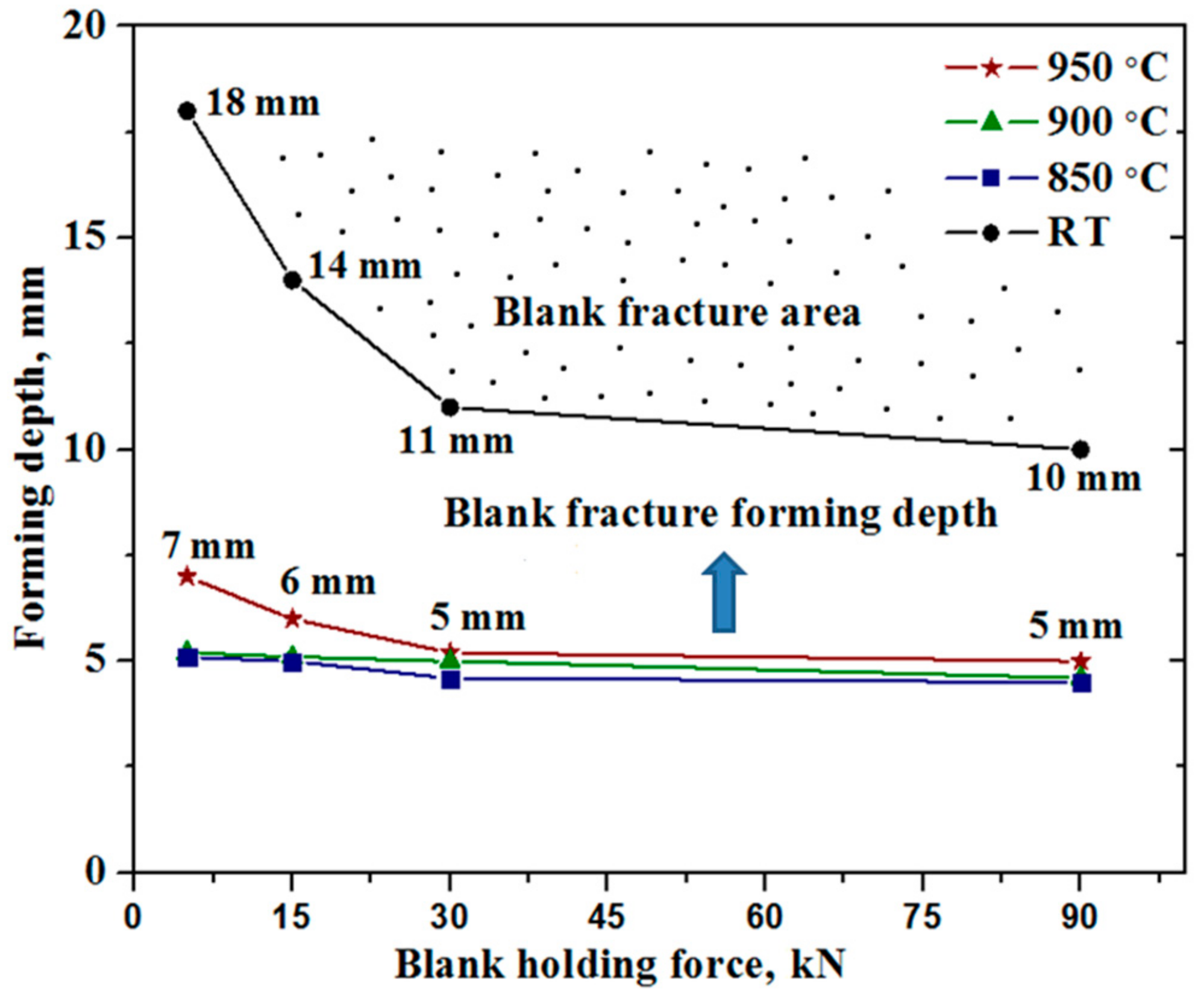
Figure 7 compares the forming depth versus blank holding forces for cold pre-deep drawing and direct hot deep drawing at different blank temperatures. The forming depth was much higher in cold pre-deep drawing than that in direct hot deep drawing. In cold pre-deep drawing (at room temperature), the forming depth values were 18 mm, 14 mm, 11 mm, and 10 mm when blank holding forces were 5 kN, 15 kN, 30 kN, and 90 kN, respectively. In direct hot deep drawing, the forming depth increased as blank temperatures increased from 850 °C to 950 °C. When blank temperatures were 950 °C, the forming depth values were 7 mm, 6 mm, 5 mm, and 5 mm at blank holding forces of 5 kN, 15 kN, 30 kN, and 90 kN, respectively. In addition, the forming depth was examined with Ts = 850 °C and 900 °C. Both in cold pre-deep drawing and direct hot deep drawing, the forming depth decreased with increasing blank holding forces. On the other hand, when blank holding force was larger than 30 kN, there was negligible difference in the forming depth regardless of blank holding forces. In deep drawing, fracture occurs at the wall part of a drawn cup because it lacks ductility under a tensile stress state, and the wall thickness of a drawn cup is affected by the blank holding force [17,18]. As blank holding forces increased, the wall thickness decreased quickly. Thus, fracture occurred more easily at a higher blank holding forces and a lower forming depth was obtained.
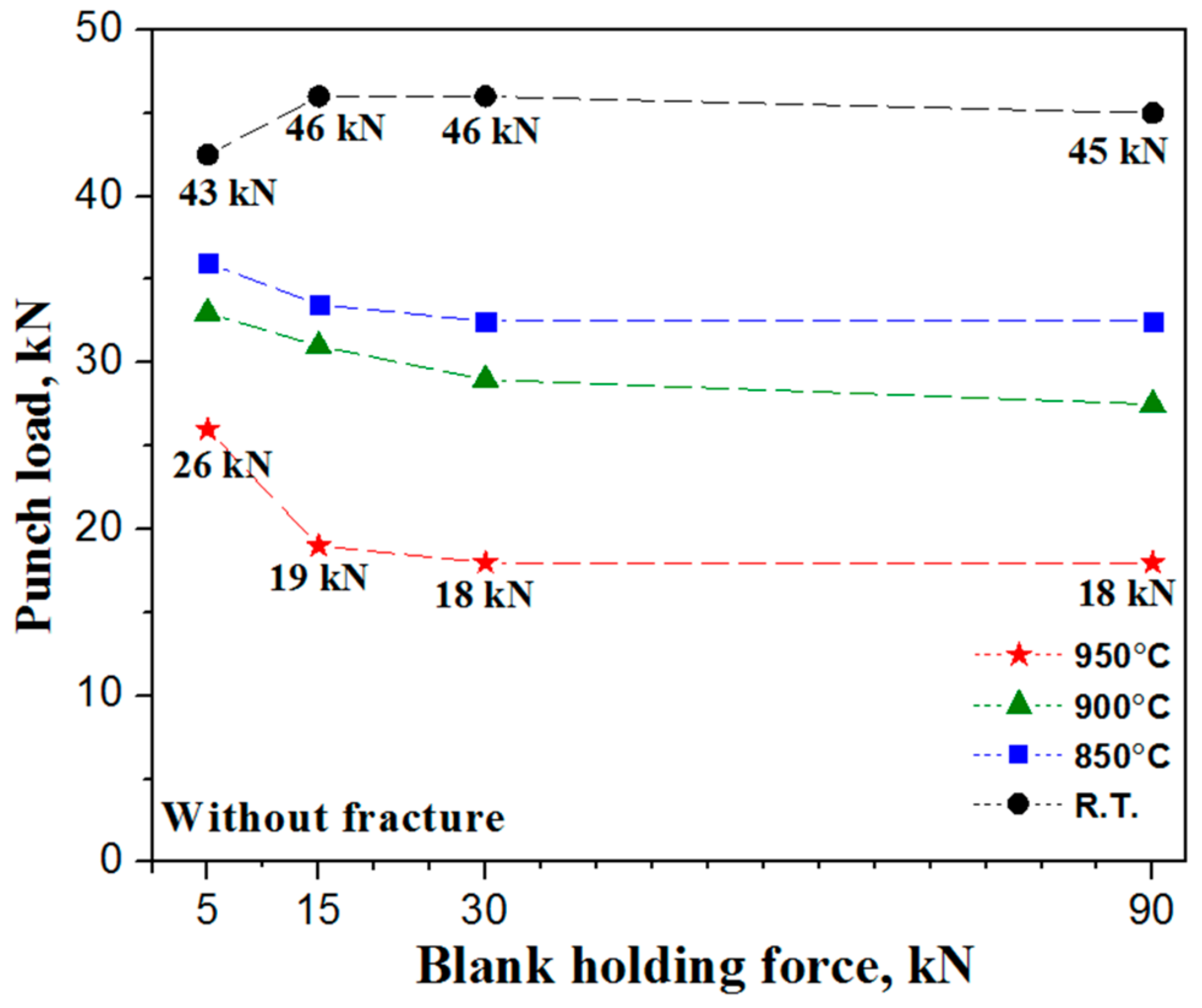
Figure 8 compares the relationships between the maximum punch load without any fracture and the blank holding force for cold pre-deep drawing and direct hot deep drawing at different blank temperatures. The maximum punch load without any fracture in cold pre-deep drawing was much higher than that in direct hot deep drawing. In direct hot deep drawing, the maximum punch load decreased when blank temperatures increased from 850 °C to 950 °C. In cold pre-deep drawing, the maximum punch load without any fracture was approximately 45 kN and did not change much with increasing blank holding force. When Ts = 950 °C, the maximum punch loads were 26 kN, 19 kN, 18 kN, and 18 kN, when the blank holding forces were 5 kN, 15 kN, 30 kN, and 90 kN, respectively. In direct hot deep drawing, the maximum punch load decreased with increasing blank holding force. The maximum punch load without any fracture was much higher when blank holding force was 5 kN compared to a higher blank holding force, and the maximum punch load without any fracture was almost the same under a high blank holding force. A lower blank temperature in the drawing process led to a higher forming force, which could be expressed as a higher punch load. The cold pre-deep drawing experiment was executed at room temperature, and the temperature remained almost the same during the drawing process. On the other hand, in the direct hot deep drawing, the blank temperature decreased during the drawing process because of the temperature difference between the blank and the tools. When the blank holding force was 5 kN, the forming depth was deeper than when blank holding force was 15 kN to 90 kN, which caused a longer drawing time, leading to a lower temperature. Consequently, the lower temperature of the blank required a higher punch load.
As stated above, a deeper forming depth can be achieved in cold pre-deep drawing than direct hot deep drawing. Although cold pre-deep drawing required a higher punch load without any fracture (43–46 kN), it was lower than the normal values in other drawing processes [19]. Thus, when the designed components were complicated and could not be finished with one stroke, indirect hot deep drawing was used widely in the automotive industry. On the other hand, in direct hot deep drawing, when blank temperatures were 950 °C, although a deeper forming depth was achieved, a lower punch load was required than when blank temperatures was 850 °C or 900 °C. This implies that Ts = 950 °C was a better condition than Ts = 900 °C or 850 °C under the same blank holding force by considering the forming depth and maximum punch load. In addition, in both cold pre-deep drawing and direct hot deep drawing, a deeper forming depth could be obtained when blank holding force was 5 kN compared with a higher blank holding force.
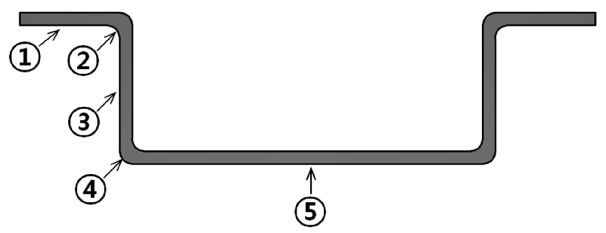
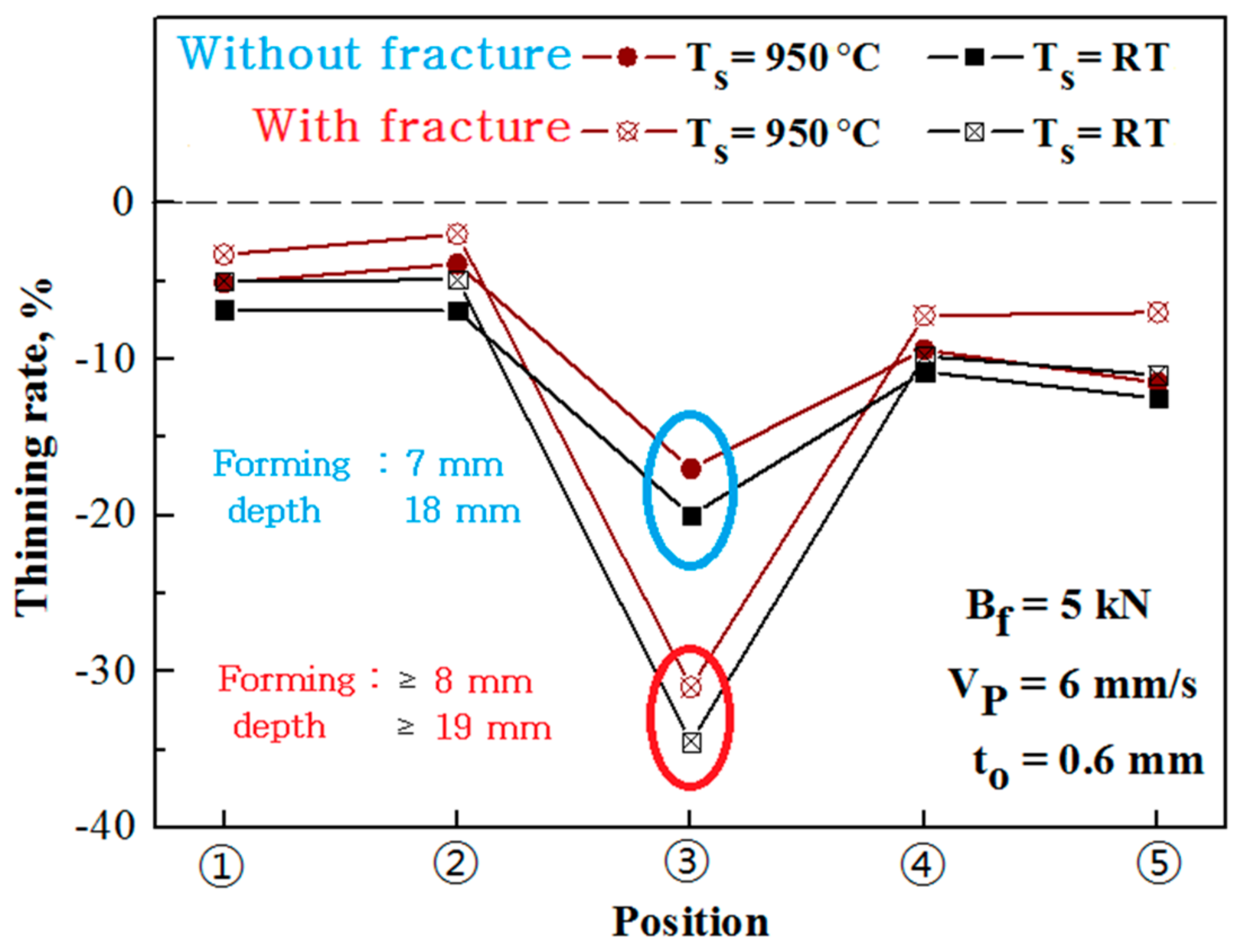
Figure 9 compares the thinning rate at each position for samples without any fracture and with fracture for direct hot deep drawing (Ts = 950 °C) and indirect hot deep drawing (RT) at Bf = 5 kN. As shown in Figure 9, the thinning rate in position ③ was much higher than the rates at the other positions. This indicated that in both direct hot deep drawing and in cold pre-deep drawing, the fracture started to occur at the wall part of the drawn cups. In the drawing process, the cup was under a tensile stress state, and the wall thickness decreased quickly. In addition, the thinning rate at each position obtained in cold pre-deep drawing was higher than that in direct hot deep drawing. In the samples without any fracture, at position ③, the thinning rate was 17% and the thickness of the blank sheet was 0.5 mm in the case of direct hot deep drawing, whereas the thinning rate was 20% and the thickness of the blank sheet was 0.48 mm in the case of cold pre-deep drawing. This means that fracture occurred more easily in cold pre-deep drawing than in direct hot deep drawing considering the thinning rate. In addition, because of the material gathering in the drawing process, the thickness at position ② was greater than at positions ①, ④, and ⑤.
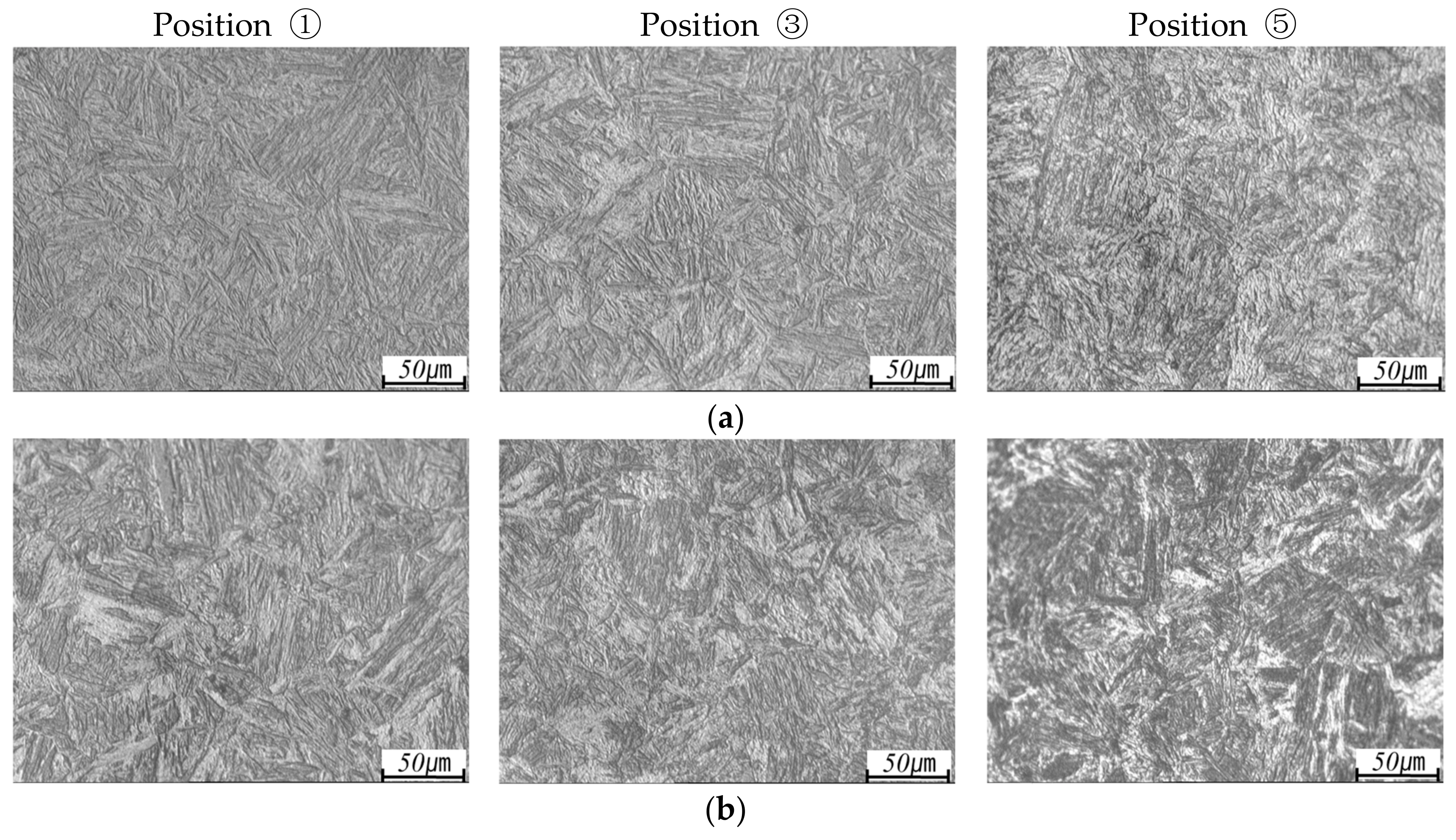
The microstructure and hardness at different positions were checked for direct and indirect hot deep drawing. Figure 10 shows the microstructure at different positions of the drawn parts for direct hot deep drawing (Ts = 950 °C) and indirect hot deep drawing when Bf = 5 kN. Temperature plays an important role in the microstructure and hardness. The drawn part was quenched more rapidly in water quenching than in-die quenching. This fast quenching speed ensured the transformation of austenite to martensite and promoted the generation of the nucleuses, with smaller nucleuses leading to higher strength and hardness values. Martensite microstructure was not found in direct hot deep drawing because both Tp and Td were kept at 300 °C in direct hot deep drawing, which led to a low quenching speed. Thus, a better microstructure was obtained in indirect hot deep drawing.
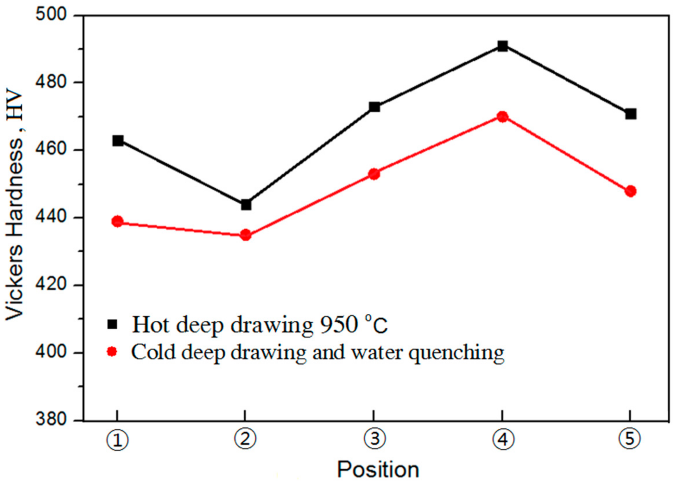
Figure 11 shows the hardness values at different positions of the drawn part for direct hot deep drawing (Ts = 950 °C) and indirect hot deep drawing when Bf = 5 kN. As can be seen, the hardness after water quenching in indirect hot deep drawing was much higher than the die quenching in direct hot deep drawing for the measured positions, which was a result of the smaller nucleuses gained from water quenching. Both in direct and indirect hot deep drawings, the highest hardness was measured at a position ④ near the punch round, which was caused by work-hardening during the drawing process. The strength and hardness of indirect hot deep drawing with water quenching were better than those of direct hot deep drawing with die quenching.

4. Conclusions

(1)
The forming depth in cold deep drawing was noticeably deeper than that in hot deep drawing. A much greater maximum punch load was achieved in cold deep drawing than hot deep drawing. Cold deep drawing was found to be a better forming process.
(2)
In hot deep drawing, for Ts = 950 °C, a deeper forming depth was achieved. Ts = 950 °C was required a lower maximum punch load than in the case of Ts = 850 °C or Ts = 900 °C.
(3)
The thinning rate at each position obtained in cold deep drawing was higher than that in hot deep drawing.
(4)
The microstructure and hardness in cold deep drawing, with water quenching after heating the drawn cups to 900 °C, were significantly better than those in hot forming at Ts = 950 °C.

Author Contributions

H.Y.S. and C.K.J. designed the experiment tools and performed the experiment. C.K.J. and C.G.K. analyzed the experimental results, whereas C.K.J. maintained and examined them. All authors have contributed to the discussions as well as revisions.

Acknowledgments

This work was supported by the National Research Foundation of Korea (NRF) grant funded by the Korea government (MSIT) through GCRC-SOP (No. 2011-0030013) and by the National Research Foundation of Korea (NRF) grant funded by the Korea government (MSIT) (No. 2017R1A2B4007884).

Conflicts of Interest

The authors declare no conflicts of interest.

References

  1. Jarvinen, H.; Honkanen, M.; Jarvenpaa, M.; Peura, P. Effect of paint baking treatment on the properties of press hardened boron sheet. J. Mater. Process. Technol. 2018, 252, 90–104. [Google Scholar] [CrossRef]
  2. Omer, K.; George, R.; Bardelcik, A.; Worswick, M.; Malcolm, S.; Detwiler, D. Development of a hot stamped channel section with axially tailored properties—Experiments and model. Int. J. Mater. Form. 2018, 11, 149–164. [Google Scholar] [CrossRef]
  3. Taylor, T.; Clough, A. Critical review of automotive hot-stamped sheet steel from an industrial perspective. Mater. Sci. Technol. 2018, 34, 809–861. [Google Scholar] [CrossRef]
  4. Li, Y.; Jeon, Y.P.; Kang, C.G. Experimental assessment of high temperature formability of boron steel sheet manufactured with a spring compound bending die. J. Eng. Mater. Technol. 2012, 134, 021019. [Google Scholar] [CrossRef]
  5. Naderi, M.; Saeed, A.; Bleck, W. The effects of non-isothermal deformation on martensitic transformation in 22MnB5 steel. Mater. Sci. Eng. A 2008, 487, 445–455. [Google Scholar] [CrossRef]
  6. Altan, T. Hot-stamping boron-alloyed steels for automotive parts. Stamp. J. 2007, 19, 10–13. [Google Scholar]
  7. Xing, Z.W.; Bao, J.; Yang, Y.Y. Hot stamping processing experiments of quenchable boron steel. Mater. Sci. Technol. 2008, 16, 172–175. [Google Scholar]
  8. So, H.; Faßmann, D.; Hoffmann, H.; Golle, R.; Schaper, M. An investigation of the blanking process of the quenchable boron alloyed steel 22MnB5 before and after hot stamping process. J. Mater. Process. Technol. 2012, 212, 437–449. [Google Scholar] [CrossRef]
  9. Nakagawa, Y.; Mori, K.I.; Maeno, T. Springback-free mechanism in hot stamping of ultra-high-strength steel parts and deformation behavior and quenchability for thin sheet. Int. J. Adv. Manuf. Technol. 2018, 95, 459–467. [Google Scholar] [CrossRef]
  10. Löbbe, C.; Tekkaya, A.E. Mechanisms for controlling springback and strength in heat-assisted sheet forming. CIRP Ann. 2018, 67, 273–276. [Google Scholar] [CrossRef]
  11. Borsetto, F.; Ghiotti, A.; Bruschi, S. Investigation of the high strength steel Al–Si coating during hot stamping operations. Key Eng. Mater. 2009, 410–411, 289–296. [Google Scholar] [CrossRef]
  12. Naderi, M. Hot Stamping of Ultra High Strength Steels. Ph.D. Thesis, RWTH Aachen University, Aachen, Germany, 2007. [Google Scholar]
  13. Ryan, G.; Alexander, B.; Michael, W. Development of a hot forming die to produce parts with tailored mechanical properties-numerical study. In Proceedings of the Hot Sheet Metal Forming of High-Preformance Steel 2th International Conference, Lulea, Sweden, 15–17 June 2009; pp. 189–198. [Google Scholar]
  14. Ouyang, Y.; Lee, M.S.; Moon, J.H.; Kang, C.G. The effect of the blank holding force on formability in hot deep drawing of boron steel considering heat transfer phenomena and friction coefficient by simulation and experimental investigation. Proc. Inst. Mech. Eng. Part B J. Eng. Manuf. 2012, 226, 1506–1518. [Google Scholar] [CrossRef]
  15. Moon, J.H.; Lee, M.S.; Seo, P.K.; Kang, C.G. A study on mechanical properties of laser-welded blank of a boron sheet steel by laser ablation variable of Al-Si coating layer. Int. J. Precis. Eng. Manuf. 2013, 14, 283–288. [Google Scholar] [CrossRef]
  16. Seok, H.H.; Mun, J.C.; Kang, C.G. Micro-crack in zinc coating layer on boron steel sheet in hot deep drawing process. Int. J. Precis. Eng. Manuf. 2015, 16, 919–927. [Google Scholar] [CrossRef]
  17. Yoshihara, S.; Manabe, K.; Nishimura, H. Effect of blank holder force control in deep-drawing process of magnesium alloy sheet. J. Mater. Process. Technol. 2005, 170, 579–585. [Google Scholar] [CrossRef]
  18. Wifi, A.; Mosallam, A. Some aspects of blank-holder force schemes in deep drawing process. JAMME 2007, 24, 315–323. [Google Scholar]
  19. Kim, H.; Sung, J.H.; Sivakumar, R.; Altan, T. Evaluation of stamping lubricants using the deep drawing test. Int. J. Mach. Tools Manuf. 2007, 47, 2120–2132. [Google Scholar] [CrossRef]
Figure 1. Engineering stress and engineering strain curve of 22MnB5 boron steel.
Metals 08 00574 g001
Figure 2. Die construction and dimension for deep drawing (unit: mm, Bf: Blank holding force, CL: clearance between punch and die).
Metals 08 00574 g002
Figure 3. Procedure of hot press forming and cold press forming: (a) direct hot press forming (hot deep drawing process); (b) indirect hot press forming (cold deep drawing process).
Metals 08 00574 g003
Figure 4. Position for the measurement of the thinning rate, microstructures and Vickers hardness.
Metals 08 00574 g004
Figure 5. Punch load versus forming depth for indirect (Ts = RT) and direct (Ts = 850, 900 and 950 °C) deep drawing at different blank holding forces: (a) Bf = 5 kN; (b) Bf = 15 kN; (c) Bf = 30 kN; (d) Bf = 90 kN.
Metals 08 00574 g005aMetals 08 00574 g005b
Figure 6. Shape of drawn cups without fracture and with fracture at different blank holding forces: (a) direct deep drawing (Ts = 950 °C); (b) indirect deep drawing (Ts = RT).
Metals 08 00574 g006
Figure 7. Relationship between forming depth and blank holding force at different blank heating temperatures.
Metals 08 00574 g007
Figure 8. Relationship between maximum punch load without fracture and blank holding force at different blank heating temperatures.
Metals 08 00574 g008
Figure 9. Thinning rate at each position for deep drawing samples with and without fracture.
Metals 08 00574 g009
Figure 10. Microstructures at ①, ③, and ⑤ of positions for hot and cold deep drawn samples: (a) hot deep drawing (Ts = 950 °C); (b) cold deep drawing and water quenching after heating temperature to 900 °C.
Metals 08 00574 g010
Figure 11. Vickers hardness at different positions of the drawn part for hot deep drawing (Ts = 950 °C) and cold deep drawing.
Metals 08 00574 g011
Table 1. Chemical composition of 22MnB5 boron steel (wt %).
CSiMnCrB
0.21230.08061.48400.40630.0016
Table 2. Experiment conditions for direct and indirect hot deep drawing process.
ParametersDirectIndirect
Blank temperature, Ts (°C)850, 900, 950Room temperature (RT)
Tool (die and punch) temperature, Td, Tp (°C)300RT
Punch speed (mm/s)66
Blank holding force, Bf (kN)5, 15, 30, 905, 15, 30, 90

