1. Introduction
Electrical discharge machining (EDM) is a widely used nontraditional machining process in industrial applications requiring high-profile accuracy and fine dimensional tolerances, especially when difficult-to-cut materials are involved. In particular, EDM drilling [
1] is a commonly used process for orifice and hole machining in the aerospace, medical [
2], molds and automotive sectors.
In an EDM process, the material is machined by electrical discharges. An electric arc is produced between the workpiece and the electrode until the desired shape is obtained. The workpiece and the electrode are submerged in a dielectric environment [
3], both are also electrical conductors [
4]. EDM is especially efficient for machining materials with high-hardness and complex geometries [
5].
However, surface defects associated with EDM, such as voids, dense white layers, serious micro cracks and heat affected areas [
6], require surface analysis [
7] in order to guarantee machined component quality [
8]. Moreover, electrode wear prediction and process parameter selection for process productivity, quality and accuracy requirements remain challenging with EDM.
In this sense, some authors study real-time monitoring techniques [
9,
10] in order to control electrode wear and to obtain an efficient EDM drilling process for nickel superalloys [
11,
12], titanium alloys [
13,
14,
15,
16], and stainless steel [
17,
18] workpieces.
Therefore, as it is often difficult to ensure the surface quality and the correct machining process, in this study, the results from EDM drilling tests in γ-TiAl are presented as a guide to ensure good surface quality and machining process performance. Within this context, different electrode materials and machining parameters were tested in order to determine optimal machining conditions. On this matter, electrode wear, surface hardness, roughness and integrity were analyzed and discussed. TiAl alloys are widely used in areas such as aerospace, jet engines, airframe components and automotives due to their excellent corrosion resistance, lightweight and mechanical properties. Titanium and aluminum [
19,
20] are the most important components together with molybdenum (1–2%), copper and silicon (0.2%). They have very good thermal and mechanical properties such as: (1) low density (4 g/cm
3); (2) high temperature resistance; (3) excellent corrosion resistance and (4) good electric and thermal conductivity.
The literature regarding these materials is relatively scarce. Jabbaripour et al. [
21] compared the powder mixed electrical discharge machining (PMEDM) and EDM process of γ-TiAl by changing the current, pulse on time, powder size and powder concentration. Shabgard et al. [
22] used the EDM process for the machining of γ-TiAl and discussed the influence of the input parameters (discharge current and duration) on the removal rate, tool wear, or compositions and phases of machined surfaces. Holsten et al. [
23] investigated the anomalous behavior of γ-TiAl, which is better machined under the conventional anodic polarity. This leads to TiC formation on the work surface.
In this work, EDM technology and process parameters are compared within two γ-TiAl types. Hole making operations using electrical discharges are made on extruded and ingot versions of this material for different machining regimes.
The MoCuSi TiAl alloy, depicted in
Figure 1, is available in two versions: extruded or ingot. They are made from the same materials but differ in the way they are obtained. The former is obtained by casting, while the latter is obtained by extrusion performed in a stainless-steel sleeve. Due to this difference, the latter is covered in stainless steel.
Recently, TiAl alloys are a vast group with important differences between products.
Table 1 shows the main differences between MoCuSi types and common Ti6Al4V. In the past, TiAl alloys were much easier to machine that the current TiAl alloys. As such, newer alloys have much lower density as well as higher maximum operating temperature. As both these properties are essential for current applications, this is a step forward for the industry.
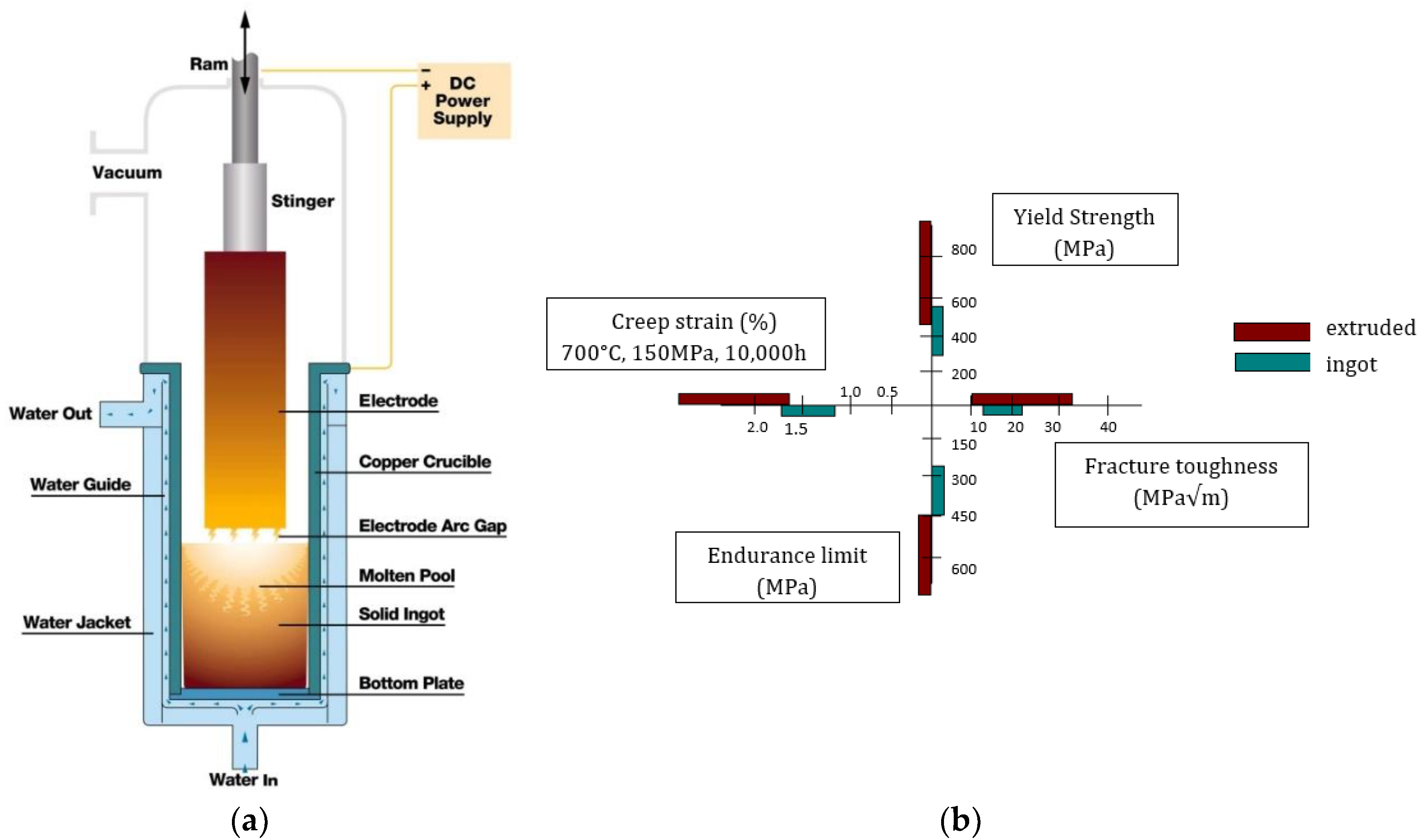
Vacuum arc remelting (VAR), depicted in
Figure 2a, is used in the manufacturing of ingots of γ-TiAl. The basic design of the VAR furnace has been continuously improved continuously, particularly in regard to computer control and regulation, with the objective of achieving a fully-automated remelting process. This has resulted in improved reproducibility of the metallurgical properties of γ-TiAl ingots.
The process involves melting the material within a vacuum-controlled atmosphere (0.13–13 Pa) in order to develop material homogeneity. VAR is the continuous remelting of a consumable electrode by means of an arc under vacuum. Direct current (DC) power is applied to strike an arc between the consumable electrode (cathode −) and the baseplate of a copper mold contained in a water jacket (anode +). The intense heat generated by the electric arc melts the tip of the electrode and a new ingot is progressively formed in the water-cooled mold.
MoCuSi ingots are obtained by VAR while extruded MoCuSi is obtained by extruding MoCuSi ingots. This difference in processing results in substantial differences in properties, shown in
Figure 2b. The extruded material [
24,
25,
26] has more desirable properties than the ingots. Yield strength, creep strain and endurance limit are much lower in the ingots than in the extruded material. The difference in the fracture toughness is less pronounced.
TiAl alloys are used for reliable components where surface integrity must be maintained. However, the machinability of titanium and its alloys is poor due to their low thermal conductivities, high chemical reactivity, and low elastic moduli, making it difficult to obtain good machining quality. To overcome these challenges, EDM could be an effective manufacturing process, especially for the manufacturing of complex geometries. In this process, a high temperature gradient can jeopardize process accuracy and the operating life of the part.
4. Conclusions
γ-TiAl alloys possess better mechanical properties than classical TiAl alloys and so, there is a chance to substitute the latter with the former. However, the lower machinability of γ-TiAl alloys is an obstacle that needs to be addressed. In this study, the machinability of two types of γ-TiAl alloys, ingot MoCuSi and extruded MoCuSi, was compared.
After material analysis, it can be concluded that, in general, MoCuSi alloys present a similar behavior.
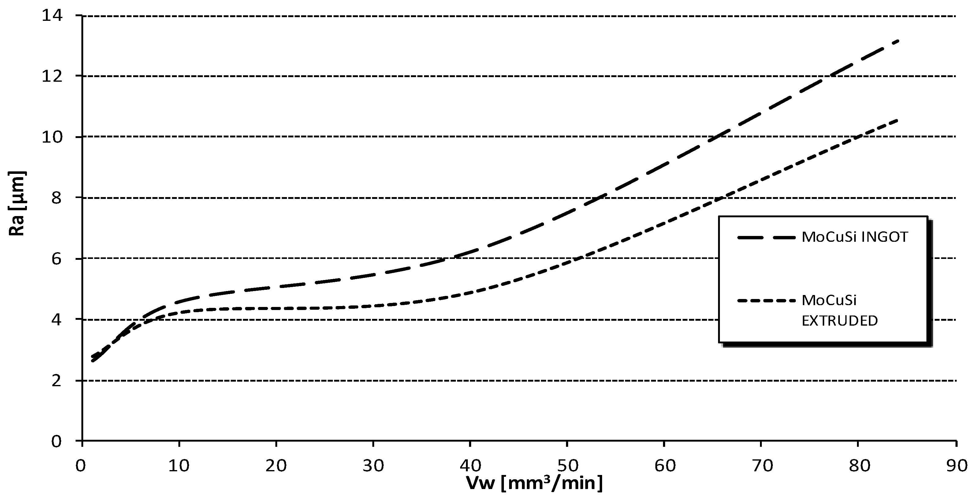
Considering the surface finish, both MoCuSi alloys present a similar behavior. The best results are obtained with the extruded MoCuSi workpiece but, in general, the difference between both is subtle.
Moreover, in roughing tests, the best results were also obtained with extruded MoCuSi: the lowest times and the best surface finish results. In the roughing test, tested parameters on the first and the fourth attempts present the best surface finish results. For the fourth attempt, the machining time was shorter than the first one. In relation to this, intensity and stage number influence was observed: higher intensity values determine shorter machining times.
In relation to hardness analysis, the extruded MoCuSi workpiece presents harder values than the MoCuSi ingot. In general, after roughing tests, higher hardness values were measured than after finishing tests. Thus, the extruded type is more preferable than the MoCusi ingot due to its superior mechanical properties.
On the other hand, regarding electrode materials, although both graphite and copper-tungsten electrodes were tested, copper-tungsten electrodes were found to be inappropriate for titanium component machining due to unstable erosion and excessive electrode wear. For that reason, graphite electrodes were used for this study.
Author Contributions
A.B. designed and performed the experiments. G.U. and A.C. analyzed roughness, hardness, electrode wear and surface integrity. Finally, L.N.L.d.L. contributed with the resources (machine, tools, material, etc.) and general supervision of the work.
Funding
Acknowledgments: Thanks are given to the UFI in Mechanical Engineering of the UPV/EHU for its support to this project, and to Spanish project DPI2016-74845-R, ESTRATEGIAS AVANZADAS DE DEFINICION DE FRESADO EN PIEZAS ROTATIVAS INTEGRALES, CON ASEGURAMIENTO DE REQUISITO DE FIABILIDAD Y PRODUCTIVIDAD and project RTC-2014-1861-4, INNPACTO DESAFIO II.
Acknowledgments
Thanks are given to the assistance from the technical specialist Eng. Garikoitz Goikoetxea at UPV/EHU.
Conflicts of Interest
The authors declare no conflict of interest. The founding sponsors had no role in the design of the study; in the collection, analyses, or interpretation of data; in the writing of the manuscript, and in the decision to publish the results.
References
- Bellotti, M.; Qian, J.; Reynaerts, D. Enhancement of the Micro-EDM Process for Drilling Through-holes. Proced. CIRP 2018, 68, 610–615. [Google Scholar] [CrossRef]
- Ho, K.H.; Newman, S.T. State of the art electrical discharge machining (EDM). Int. J. Mach. Tools Manuf. 2003, 43, 1287–1300. [Google Scholar] [CrossRef]
- Bojorquez, B.; Marloth, R.T.; Es-Said, O.S. Formation of a crater in the work piece on an electrical discharge machine. Eng. Fail. Anal. 2002, 9, 93–97. [Google Scholar] [CrossRef]
- Marafona, J.; Chousal, J.A.G. A finite element model of EDM based on the Joule effect. Int. J. Mach. Tools Manuf. 2005, 46, 1–8. [Google Scholar] [CrossRef]
- Mai, C.; Hocheng, H.; Huang, S. Advantages of carbon nanotubes in electrical dis-charge machining. Int. J. Adv. Manuf. Technol. 2012, 59, 111–117. [Google Scholar] [CrossRef]
- Tzeng, Y.F.; Lee, C.Y. Effects of powder characteristics on electrodischarge machining efficiency. Int. J. Adv. Manuf. Technol. 2001, 17, 586–592. [Google Scholar] [CrossRef]
- Mohammadreza, S.; Behnam, K. Investigation of carbon nanotube added dielectric on the surface characteristics and machining performance of Ti–6Al–4V alloy in EDM process. J. Manuf. Process. 2017, 25, 212–219. [Google Scholar] [CrossRef]
- Hsu, W.-H.; Chien, W.-T. Effect of Electrical Discharge Machining on Stress Concentration in Titanium Alloy Holes. Materials 2016, 9, 957. [Google Scholar] [CrossRef] [PubMed]
- Nirala, C.K.; Saha, P. Precise μEDM-drilling using real-time indirect tool wear compensation. J. Mater. Process. Technol. 2017, 240, 176–189. [Google Scholar] [CrossRef]
- Aligiri, E.; Yeo, S.; Tan, P. A new tool wear compensation method based on real-time estimation of material removal volume in micro-EDM. J. Mater. Process. Technol. 2010, 210, 2292–2303. [Google Scholar] [CrossRef]
- Kliuev, M.; Boccadoro, M.; Perez, R.; Dal Bó, W.; Stirnimann, J.; Kuster, F.; Wegener, K. EDM Drilling and Shaping of Cooling Holes in Inconel 718 Turbine Blades. Proced. CIRP 2016, 42, 322–327. [Google Scholar] [CrossRef]
- Torres, A.; Puertas, I.; Luis, C.J. EDM machinability and surface roughness analysis of INCONEL 600 using graphite electrodes. Int. J. Adv. Manuf. Technol. 2016, 84, 2671–2688. [Google Scholar] [CrossRef]
- Yilmaz, O.; Okka, M.A. Effect of single and multi-channel electrodes application on EDM fast hole drilling performance. Int. J. Adv. Manuf. Technol. 2010, 51, 185–194. [Google Scholar] [CrossRef]
- Yadav, U.S.; Yadava, V. Experimental Investigation on Electrical Discharge Drilling of Ti-6Al-4V Alloy. Mach. Sci. Technol. 2015, 19, 515–535. [Google Scholar] [CrossRef]
- Lin, M.Y.; Tsao, C.C.; Huang, H.H.; Wu, C.Y.; Hsu, C.Y. Use of the grey Taguchi method to optimise the micro-electrical discharge machining (micro-EDM) of Ti-6Al-4V alloy. Int. J. Comput. Integr. Manuf. 2014, 28, 569–576. [Google Scholar] [CrossRef]
- Meena, V.K.; Azad, M.S. Grey Relational Analysis of Micro-EDM Machining of Ti-6Al-4V Alloy. Mater. Manuf. Process. 2012, 27, 973–977. [Google Scholar] [CrossRef]
- Rashed, C.A.A.; Romoli, L.; Tantussi, F.; Fuso, F.; Bertoncini, L.; Fiaschi, M.; Allegrini, M.; Dini, G. Experimental optimization of micro-electrical discharge drilling process from the perspective of inner surface enhancement measured by shear-force microscopy. CIRP J. Manuf. Sci. Technol. 2014, 7, 11–19. [Google Scholar] [CrossRef]
- D’Urso, G.; Maccarini, G.; Quarto, M.; Ravasio, C. Investigation on power discharge in micro-EDM stainless steel drilling using different electrodes. J. Mech. Sci. Technol. 2015, 29, 4341–4349. [Google Scholar] [CrossRef]
- López de Lacalle, L.N.; Lamikiz, A. Machine Tools for High Performace Machining, 1st ed.; Springer: London, UK, 2009; ISBN 978-1848003798. [Google Scholar]
- Sharman, A.R.C.; Aspinwall, D.K.; Dewes, R.C.; Bowen, P. Workpiece surface integrity considerations when finish turning gamma titanium aluminide. Wear 2001, 249, 473–481. [Google Scholar] [CrossRef]
- Jabbaripour, B.; Sadeghi, M.H.; Shabgard, M.R. Investigating surface roughness, material removal rate and corrosion resistance in PMEDM of γ-TiAl intermetallic. J. Manuf. Process. 2013, 15, 56–68. [Google Scholar] [CrossRef]
- Shabgard, M.; Faraji, H.; Khosrozadeh, B.; Amini, K.; Seyedzavvar, M. Experimental investigation into the EDM process of gamma-TiAl. Turk. J. Eng. Environ. Sci. 2014, 38, 231–239. [Google Scholar] [CrossRef]
- Holsten, M.; Koshy, P.; Klink, A.; Schwedt, A. Anomalous influence of polarity in sink EDM of titanium alloys. CIRP Ann. 2018, in press. [Google Scholar] [CrossRef]
- Olvera, D.; Urbikain, G.; Beranoagirre, A.; López de Lacalle, L.N. Hole Making in Gamma TiAl, 1st ed.; DAAAM International Publications: Wien, Austria, 2010; pp. 337–347. ISBN 978-3-901509-86-5. [Google Scholar]
- Beranoagirre, A.; Olvera, D.; López de Lacalle, L.N.; Urbicain, G. Drilling of Intermetallic Alloys Gamma TiAl. AIP Conf. Proc. 2011, 1315, 1023–1028. [Google Scholar]
- Lee, P.; Altintas, Y. Prediction of ball-end milling forces from orthogonal cutting data. Int. J. Mach. Tools Manuf. 1996, 36, 1059–1072. [Google Scholar] [CrossRef]
Figure 1.
MoCuSi (a) ingot and (b) extruded. (courtesy of GfE® Metalle und Materialien GmbH).
Figure 2.
(a) Vacuum arc remelting (VAR) furnace (adapted from ATI Allvac©); (b) properties of extruded and ingot TiAl.
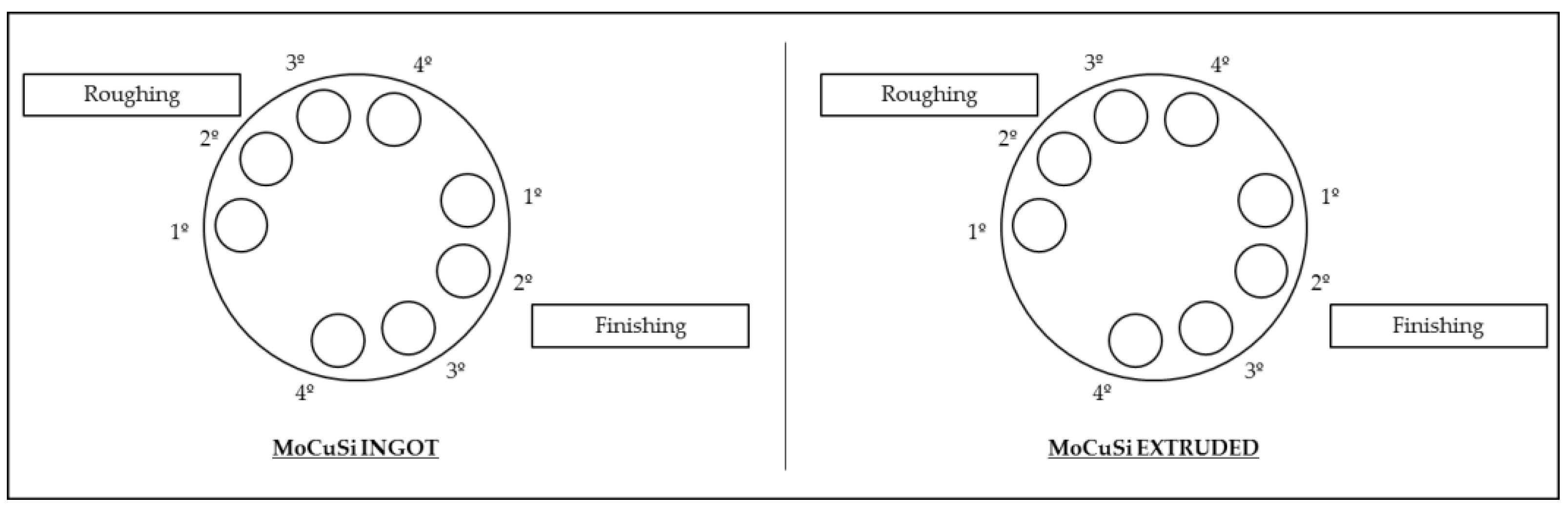
Figure 3.
Scheme of electrical discharge machining (EDM) operations for both materials ordered by hole number.
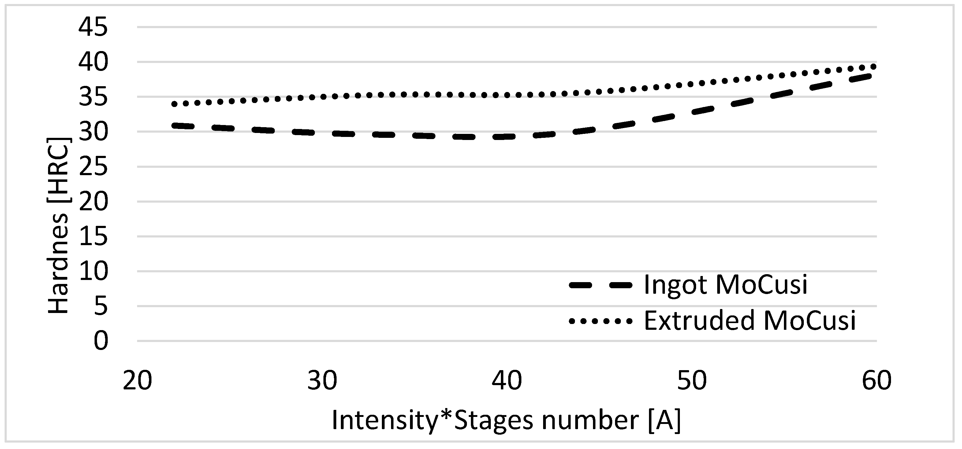
Figure 4.
Comparison of hardness/intensity in finishing for both materials.
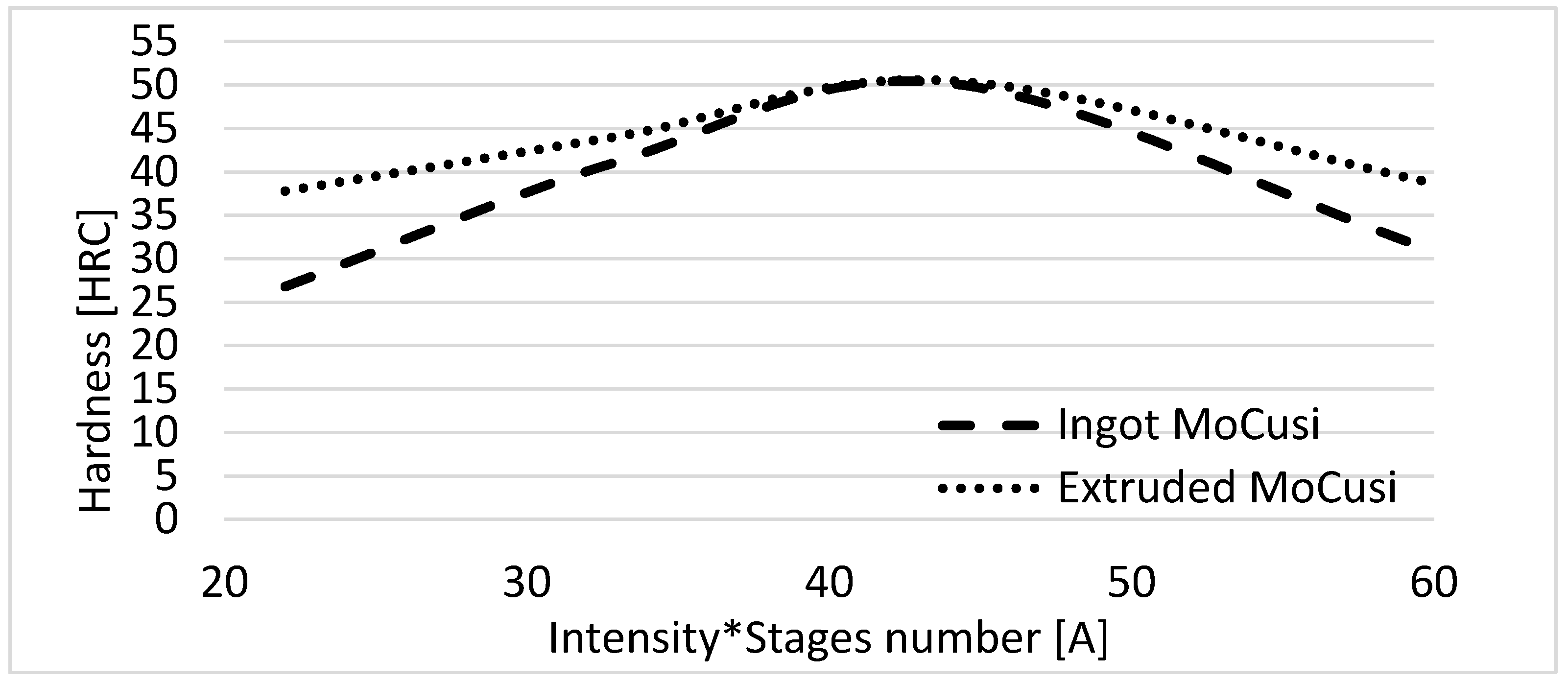
Figure 5.
Comparison of hardness/intensity in roughing for both materials.
Figure 6.
Surface finish and machining volume for the ingot and extruded MoCuSi.
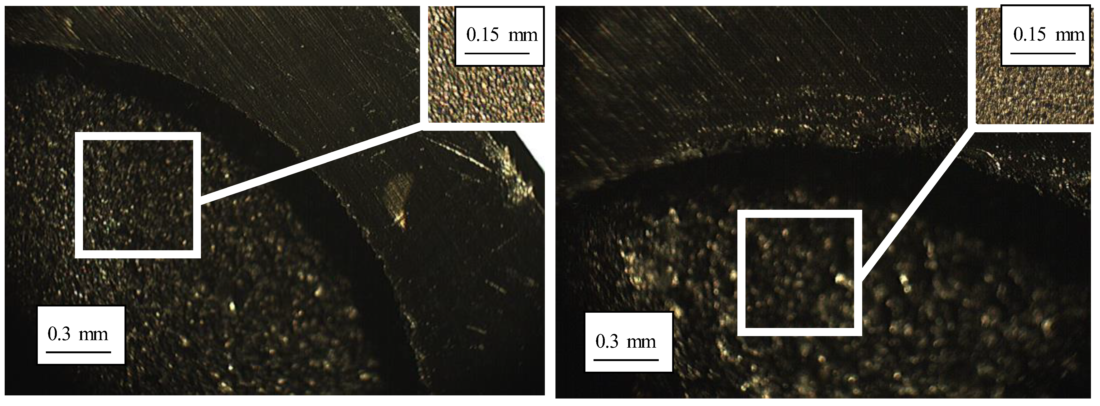
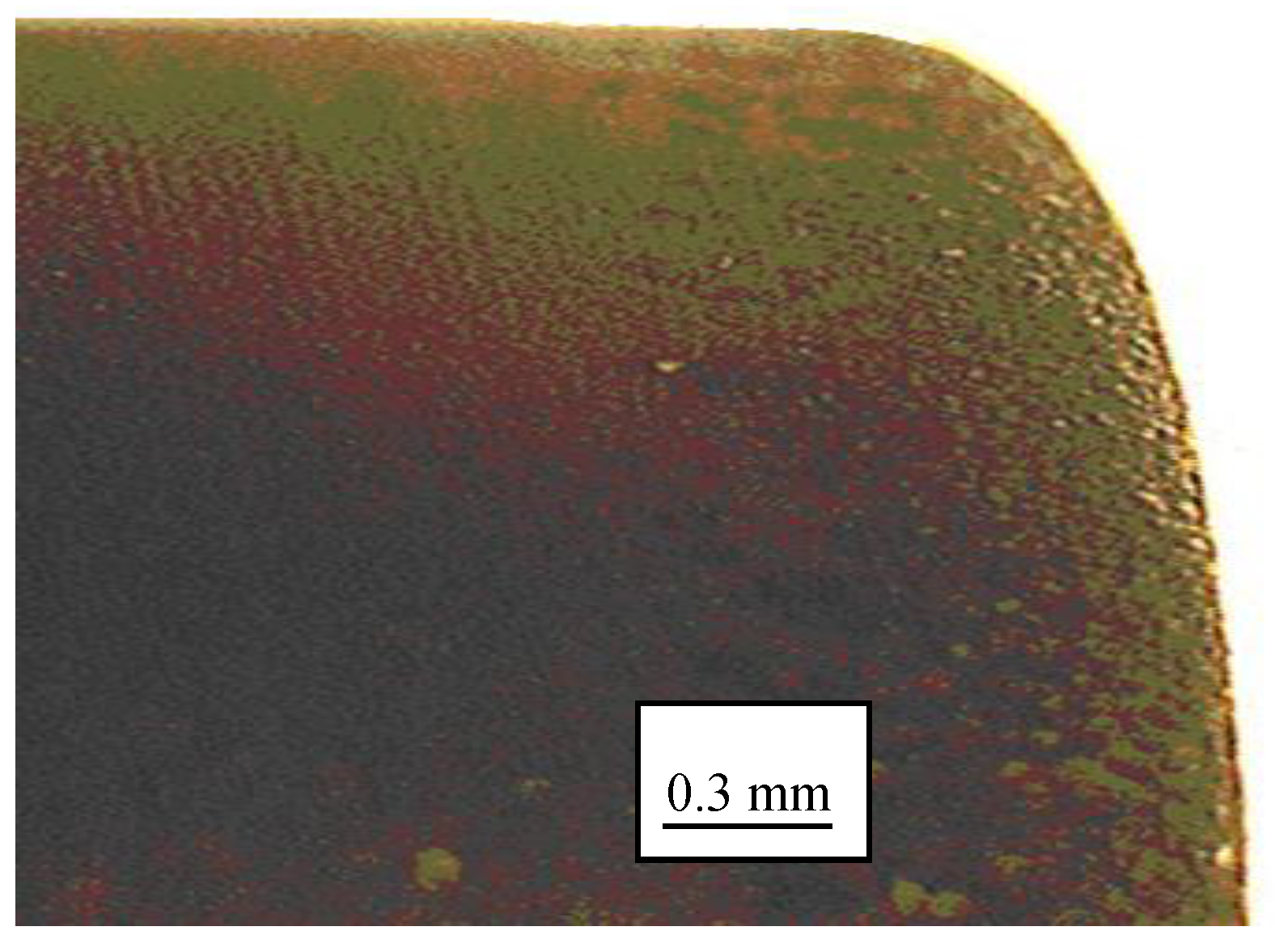
Figure 7.
Details of the best (left) and worst (right) edge and surface finish with the MoCuSi ingot.
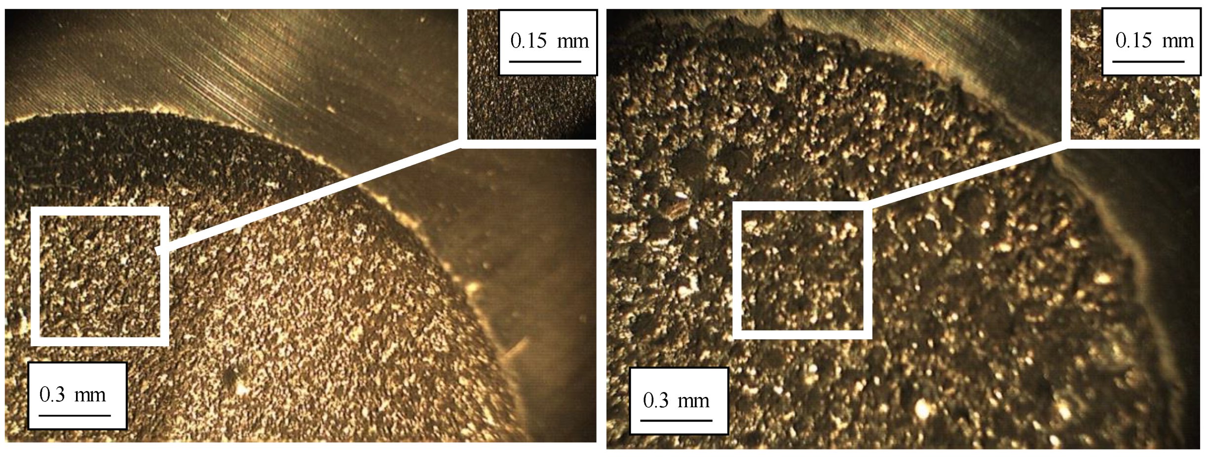
Figure 8.
Details of the best (left) and worst (right) edge and surface finish with the MoCuSi ingot.
Figure 9.
The difference between the graphite electrode before and after being used.
Figure 10.
The profile of the graphite electrode after being used.
Table 1.
Properties of different TiAl alloys (courtesy of GfE® Metalle und Materialien GmbH).
| Properties | MoCuSi Extruded | MoCuSi Ingot | Ti–6Al–4V (Annealed) |
|---|
| Density (g/cm3) | 3.74 | 3.88 | 4.49 |
| Specific modulus (GPa/kg/m3) | 43 | 37 | 24 |
| Tensile strength (MPa) | 607 | 689 | 1087 |
| Specific strength (MPa/(g/cm3)) | 162 | 178 | 242 |
| Yield strength (MPa) | 589 | 570 | 942 |
| Ductility (% elongation) | 1.7 | 2.4 | 7.8 |
| Fracture toughness (MPa·m1/2) | 23 | 20 | 52 |
| Thermal conductivity (W/m/K) | 24 | 19 | 8.6 |
| Maximum operating temperature (°C) | 900 | 865 | 615 |
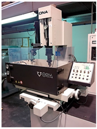
Table 2.
ONA© Compact 2 characteristics.
![Metals 08 00543 i001]() | X-Y-Z axes travel | 350 × 250 × 380 mm |
| Machine dimensions | 1000 × 750 × 2000 mm |
| Worktable dimensions | 550 × 360 mm |
| Allowable weight on table | 350 kg |
| Generator intensity | 30 A |
| Voltage levels | 9 |
| Electrode diameter | 0.2–3 mm |
| Water tank capacity | 25 L |
Table 3.
Properties of selected graphite electrodes (courtesy of matweb©).
| Properties | Graphite |
|---|
| Density (kg/m3) | 1800 |
| Particle size | 1–5 µm |
| Bending resistance (kg/m2) | 5.3 × 10⁶ |
| Compression resistance (kg/m2) | 10.50 × 10⁶ |
| Hardness (HB) | 70 |
| Electrical resistivity (µΩ) | 16 |
Table 4.
Roughing parameters for the MoCuSi ingot.
| Test | Intensity (A) | Stages Number | ti (µs) | to (µs) | Lateral Gap (µm) | Removed Material Vol. Vw (mm3/min) |
|---|
| 1° | 1 | 2 | 4 | - | x 3 | 200 | 20 | 80 | 101 |
| 2° | 1 | 2 | 4 | 8 | x 2 | 200 | 20 | 120 | 170 |
| 3° | 1 | 2 | 4 | 8 | x 3 | 200 | 30 | 140 | 270 |
| 4° | 1 | 2 | 4 | 8 | x 4 | 200 | 30 | 150 | 330 |
Table 5.
Roughing parameters for the extruded MoCuSi.
| Test | Intensity (A) | Stages Number | ti (µs) | to (µs) | Lateral Gap (µm) | Removed Material Vol. Vw (mm3/min) |
|---|
| 1° | 1 | 2 | 4 | - | x 3 | 200 | 30 | 80 | 101 |
| 2° | 1 | 2 | 4 | 8 | x 2 | 270 | 20 | 120 | 170 |
| 3° | 1 | 2 | 4 | 8 | x 3 | 200 | 30 | 140 | 270 |
| 4° | 1 | 2 | 4 | 8 | x 4 | 200 | 30 | 150 | 330 |
Table 6.
Finishing parameters for MoCuSi ingot.
| Test | Intensity (A) | Stages Number | ti (µs) | to (µs) | Ra (µm) | Type of Finish | Removed Material Vol. Vw (mm3/min) |
|---|
| 1° | 1 | 2 | - | - | x 1 | 16 | 6 | 1.6 | N7 | 1.2 |
| 2° | 1 | 2 | - | - | x 2 | 50 | 6 | 3.2 | N8 | 10 |
| 3° | 1 | 2 | - | - | x 4 | 200 | 12 | 6.3 | N9 | 42 |
| 4° | 1 | - | - | - | x 2 | 150 | 6 | 12.6 | N10 | 84 |
Table 7.
Finishing parameters for the extruded MoCuSi.
| Test | Intensity (A) | Stages Number | ti (µs) | to (µs) | Ra (µm) | Type of Finish | Removed Material Vol. Vw (mm3/min) |
|---|
| 1° | 1 | 2 | - | - | x 1 | 16 | 12 | 1.6 | N7 | 1.2 |
| 2° | 1 | 2 | - | - | x 2 | 50 | 12 | 3.2 | N8 | 10 |
| 3° | 1 | 2 | - | - | x 4 | 200 | 12 | 6.3 | N9 | 42 |
| 4° | 1 | - | - | - | x 2 | 150 | 12 | 12.6 | N10 | 84 |
Table 8.
Roughing results for the ingot MoCuSi.
| Roughing MoCuSi Ingot |
|---|
| Hole | Test | Time | Weight (g) | Height Wear (mm) | Hole Diameter (mm) | Hole Diameter Average (mm) | Electrode Diameter (mm) | Lateral Gap (mm) |
|---|
| Roughing 1 | 1 | 1 h 29 min | 9.86 | 0.93 | 18.68 | 18.63 | 18.50 | 0.13 |
| 2 | 18.67 |
| 3 | 18.68 |
| Roughing 2 | 1 | 1 h 3 min | 9.38 | 0.76 | 18.68 | 18.65 | 0.15 |
| 2 | 18.67 |
| 3 | 18.67 |
| Roughing 3 | 1 | 40 min | 9.86 | 0.85 | 18.69 | 18.69 | 0.19 |
| 2 | 18.68 |
| 3 | 18.69 |
| Roughing 4 | 1 | 1 h 8 min | 8.64 | 0.91 | 18.67 | 18.63 | 0.13 |
| 2 | 18.66 |
| 3 | 18.65 |
| Weight of the electrode at the beginning (g) | 8.19 |
| Weight of the electrode at the end (g) | 6.08 |
Table 9.
Roughing results for the extruded MoCuSi.
| Roughing MoCuSi Extruded |
|---|
| Hole | Attempt | Time | Weight (g) | Height Wear (mm) | Hole Diameter (mm) | Hole Diameter Average (mm) | Electrode Diameter (mm) | Lateral Gap (mm) |
|---|
| Roughing 1 | 1 | 31 min | 7.64 | 0.95 | 18.68 | 18.68 | 18.50 | 0.18 |
| 2 | 18.67 |
| 3 | 18.68 |
| Roughing 2 | 1 | 1 h | 7.08 | 0.90 | 18.68 | 18.67 | 0.17 |
| 2 | 18.67 |
| 3 | 18.67 |
| Roughing 3 | 1 | 45 min | 6.56 | 1.05 | 1869 | 18.69 | 0.19 |
| 2 | 18.68 |
| 3 | 18.69 |
| Roughing 4 | 1 | 36 min | 6.08 | 1.00 | 18.67 | 18.66 | 0.16 |
| 2 | 18.66 |
| 3 | 18.66 |
| Weight of the electrode at the beginning (g) | 8.19 |
| Weight of the electrode at the end (g) | 6.08 |
Table 10.
Hardness with MoCuSi ingot/extruded roughing.
| MoCuSi Ingot | MoCuSi Extruded |
|---|
| Measurement area | Tests | Tests |
| 1 | 2 | 3 | Average | 1 | 2 | 3 | Average |
| Without erosion | 31.7 | 28.3 | 31.1 | 30.4 | 32 | 34.6 | 34.5 | 33.7 |
| Finishing 1 | 30.4 | 29.8 | 32.6 | 30.9 | 34.7 | 32.3 | 34.9 | 34.0 |
| Finishing 2 | 30.2 | 30.6 | 27.9 | 29.6 | 35.8 | 34.6 | 35.4 | 35.3 |
| Finishing 3 | 27.9 | 30.8 | 31.7 | 30.1 | 36.4 | 35.4 | 35 | 35.6 |
| Finishing 4 | 37.5 | 39.5 | 37.7 | 38.2 | 35.7 | 38.9 | 43.7 | 39.4 |
| Roughing 1 | 26.2 | 24.4 | 29.8 | 26.8 | 45.3 | 41.5 | 26.5 | 37.8 |
| Roughing 2 | 32.9 | 48.2 | 42.4 | 41.2 | 38.5 | 42.1 | 51.8 | 44.1 |
| Roughing 3 | 54.6 | 46.7 | 49.2 | 50.2 | 39.7 | 52 | 59.8 | 50.5 |
| Roughing 4 | 32 | 25.9 | 34.7 | 30.9 | 46.8 | 36 | 33.4 | 38.7 |
Table 11.
Results for surface finish with the ingot MoCuSi.
| Graphite Electrode and MoCuSi Ingot Piece |
|---|
| Test | Ra (µm) | Rz (µm) | Rt (µm) | Finish Type | Theoretical Steel Finish |
|---|
| 1° | 2.654 | 16.682 | 23.676 | N8 | N7 |
| 2° | 4.583 | 24.999 | 34.282 | N9 | N8 |
| 3° | 6.443 | 36.948 | 45.181 | N10 | N9 |
| 4° | 13.165 | 79.028 | 116.375 | N11 | N10 |
| Length | 4.8 mm |
Table 12.
Results for surface finish with the extruded MoCuSi.
| Graphite and MoCuSi Extruded Piece |
|---|
| Test | Ra (µm) | Rz (µm) | Rt (µm) | Finish Type | Theoretical Steel Finish |
|---|
| 1° | 2.786 | 18.554 | 20.605 | N8 | N7 |
| 2° | 6.989 | 40.692 | 49.935 | N10 | N8 |
| 3° | 5.030 | 32.020 | 45.207 | N9 | N9 |
| 4° | 10.533 | 55.518 | 71.361 | N10 | N10 |
| Length | 4.8 mm |
© 2018 by the authors. Licensee MDPI, Basel, Switzerland. This article is an open access article distributed under the terms and conditions of the Creative Commons Attribution (CC BY) license (http://creativecommons.org/licenses/by/4.0/).


