Article

Medium-Frequency Electrical Resistance Sintering of Oxidized C.P. Iron Powder

by
Juan Manuel Montes
1,
Francisco Gómez Cuevas
2,
Fátima Ternero
1,*,
Raquel Astacio
1,
Eduardo Sánchez Caballero
1 and
Jesús Cintas
1
1
Metallurgy and Materials Engineering Group Escuela Técnica Superior de Ingeniería, Universidad de Sevilla Camino de los Descubrimientos s/n, 41092 Sevilla, Spain
2
Department of Chemical Engineering, Physical Chemistry and Materials Science Escuela Técnica Superior de Ingeniería, Universidad de Huelva Campus El Carmen, Avda. Tres de Marzo s/n, 21071 Huelva, Spain
*
Author to whom correspondence should be addressed.
Metals 2018, 8(6), 426; https://doi.org/10.3390/met8060426
Submission received: 10 May 2018 / Revised: 24 May 2018 / Accepted: 4 June 2018 / Published: 6 June 2018

Abstract

:
Commercially pure (C.P.) iron powders with a deliberate high degree of oxidation were consolidated by medium-frequency electrical resistance sintering (MF-ERS). This is a consolidation technique where pressure, and heat coming from a low-voltage and high-intensity electrical current, are simultaneously applied to a powder mass. In this work, the achieved densification rate is interpreted according to a qualitative microscopic model, based on the compacts global porosity and electrical resistance evolution. The effect of current intensity and sintering time on compacts was studied on the basis of micrographs revealing the porosity distribution inside the sintered compact. The microstructural characteristics of compacts consolidated by the traditional cold-press and furnace-sinter powder metallurgy route are compared with results of MF-ERS consolidation. The goodness of MF-ERS versus the problems of conventional sintering when working with oxidized powders is analyzed. The electrical consolidation can obtain higher densifications than the traditional route under non-reducing atmospheres.

1. Introduction

The electricity can be used to sinter a conductive powder mass that is passed through by the current, as has been suggested numerous times during the last century, and still remaining as an issue of extraordinary interest at present. The progress of the different modalities of electrical sintering, usually known under the common name of FAST (field assisted sintering techniques), has been reviewed in detail by Grasso et al. [1].
Although with a common name, there are important differences among these techniques, mainly due to: (a) the characteristics of the power source, (b) the electrical features of the die containing the powders, and (c) the time that process lasts (from microseconds to minutes). This strongly influences the physical phenomena taking place in the different processes.
Most probably, the FAST modality most widely studied is the so called spark plasma sintering (SPS), where a pulsed DC current directly passes through a graphite die, as well as through the powder compact, in case of conductive samples. This facilitates a relatively high heating rate (up to 1000 K/min), hence the sintering process being generally quite fast (within a few minutes). The main advantages of the technique are the possibility of sintering both conductive and non-conductive powders, achieving a reasonably uniform temperature distribution, whereas its disadvantages are the need of a vacuum system and complicated electronics capable of controlling the high-power pulsating current to be generated. The pulsed current, besides the Joule heating, is supposed to favor the mobility of the atoms on the particles surface, which would cause plasma and discharges between particles. Whether plasma is generated has not yet been confirmed, especially when non-conductive ceramic powders are compacted.
However, in case of sintering conductive powders, the equipment needed to undertake electrical consolidation can be greatly simplified. Regarding the many conceived modalities, maybe the simplest is one of the firstly proposed, consisting in a high intensity and low voltage electrical current passing through a powder mass of conductive powders placed inside an insulating die, and being simultaneously under pressure. This is therefore a hot consolidation technique, where the heat is generated in the powder itself by Joule effect. Such technique was described by Taylor in 1933 [2], and systematically studied later by Lenel [3], who coined the term ‘electrical resistance sintering’ (ERS) under pressure.
Among the advantages of this technique, as compared to the traditional route of cold pressing followed by furnace sintering [4,5], it should be considered: (1) the use of relatively low pressures (around 100 MPa) to reach high densification rates; (2) the need of very short dwelling times (around 1 s); and (3) the possible option of sintering in air, without protective atmospheres. The main drawbacks come from the difficulty of getting a homogeneous temperature distribution inside the powder mass, and from finding the proper die material with a good durability. Other drawbacks arise from the insufficient theoretical knowledge that still exists of the various mechanisms involved [6]. In spite of this, the interest towards the electrical sintering techniques has been growing rapidly in the last 30 years, mainly in applications involving hard-to-sinter materials, such as amorphous or nanocrystalline structures, nanocomposites, hard metals, and refractory materials [7,8].
On the other hand, it is a well-known fact [9] the problems arising during conventional sintering of highly oxidized particles when reducing atmospheres are not used. The oxide layer act to impede atomic diffusion and metal-metal contacts between particles, therefore resulting in a deficient sintering.
In this paper, the novel medium frequency electrical resistance sintering (MF-ERS) technology will be used with oxidized iron particles. Medium frequency technology is a loan from the field of resistance welding. This technology has been extensively tested and its benefits in improving electronic current control and reducing the size of the required transformers are well known. The adaptation of a welding machine for the new consolidation task is therefore simple, economical, and free of prototyping steps. The compacts densification and electrical resistance evolution during the MF-ERS process will be registered and related to the observed microstructure. Also, metallographic observations of diametrical sections of the MF-ERS compacts will be compared with those obtained by the conventional powder metallurgy (PM) route.

2. Experimental Equipment and Materials

2.1. MF-ERS Equipment

There is not a commercial equipment exactly designed to implement the MF-ERS process. However, both the mechanical and electrical requirements are effectively fulfilled by a resistance welding equipment. Welding machines have, up to recently, worked with monophasic and low frequency electric supply (about 50 Hz), but the irruption of the medium frequency technology (about 1000 Hz) has brought about a remarkable change. It has made possible the reduction of core size and weight of the welding transformer without decreasing its power, and also the use of direct current. Direct current eliminates the effect of the inductive resistance (inductance) in the secondary circuit, making the use of longer welding arms possible, but also avoids the current discontinuities, generating more heat for the same welding time. Additionally, the three-phase current of the MF technology is symmetrical and equilibrated, reducing the primary currents and letting lower cable sections and protection devices, therefore reducing costs. These benefits in the welding field are also expected to be beneficial for the MF-ERS process.
In this work, a Serra Soldadura S.A. (Spain) press-type resistance welding machine was adapted. The current intensity is electronically controlled, having a 1000 Hz medium frequency 100 kVA three-phase transformer, and servodrived upper head with a force capacity of 15 kN. The head displacement, applied load, and voltage and intensity are monitored during the process by appropriate sensors. The powder containing die consisted in a 12 mm diameter alumina tube reinforced by a steel hoop, in a similar way to the arrangement used by Lenel [3]. The ceramic die is closed with upper and lower temperature-resistant Cu electrodes (98.9% Cu, 1% Cr, 0.1% Zr), which are in contact with electroerosion resistant and nonsticking heavy metal wafers 75.3% W–24.6% Cu. These wafers, with low thermal conductivity, have the additional objective of damping the heat evacuation from the powder to the water-refrigerated electrodes. The powder to be sintered is placed between both wafers (Figure 1).

2.2. Material and Experimental Procedure

A c.p. iron powder (Fe WPL200, QMP, Mönchengladbach, Germany) was chosen as starting material. Powders were subjected to a heat treatment at 300 °C for 10 min in air to promote the oxide forming on the powders surface. The main impurities are 0.01 wt % C, 0.2 wt % Mn, and 0.2 wt % O (the latter figure is too high and it hinders the conventional sintering process, because oxygen is mainly found on the surface of the particles, in the form of oxides, preventing atomic diffusion). The apparent density of the powder [10] is 2.65 g/cm3 (a 33.7% of the absolute density) and the mean particle size 78 μm (Figure 2). The powder mass in the experiments was 3.5 g, enough to reach after consolidation a height/diameter aspect ratio near 1/2. Initially, powders are vibrated inside the die up to reach their tap density [11], of 4.45 g/cm3.
The sequence of a typical MF-ERS experiment (Figure 3) begins with a cold-pressing period (with a fixed duration of 1000 ms), where the pressure is constant and no current is applied. Then, a heating and pressing period takes place, with electrical current being applied. The sequence finishes with a cooling/forging period (fixed at 300 ms) when only pressure acts.
MF-ERS experiments were carried out with different current intensities and heating times. Tested intensities were 6, 8, and 10 kA, and heating times of 400, 700, and 1000 ms were chosen. These intensities, normalized with the cross-section of the compacts, represent current densities between 5.3 and 8.8 kA/cm2. Intensities lower than 6 kA did not successfully consolidate the powder mass for times as low as 400 ms. Intensities higher than 10 kA combined with times in the order or higher than 1000 ms resulted in compacts welded to the wafers.
All the experiments were carried out with an applied pressure of 100 MPa, which provokes a porosity reduction from a 55% to approximately 43%. A quite lower pressure does not guarantee the current passing, and a quite higher one could reduce the die life-time, but could also provoke a deficient sintering. This is because a highly densified powder during the cold compaction stage results in a very low electrical resistivity powder, and the thermal power dissipated by the Joule effect decreases, even to the limit of being insufficient to produce a higher densification and a proper consolidation. It would then be necessary a higher intensity, resulting a process more difficult to control.
Previously to each MF-ERS experiment, the inner die wall was lubricated with a thin graphite layer through a graphite-acetone suspension, also resulting in an unsticking effect.
The electrical resistance evolution during the process was determined from the measurements of voltage and circulating current between the electrodes. The porosity variation in the powder mass was determined from the registered upper electrode displacement and the measurement of the compact final porosity. This final porosity is determined by measuring the compact dimensions and weight. Height and diameter were determined from eight different values, angularly equispaced. Although the measurement by the Archimedes method guaranties a lower uncertainty for very low porosities, this is not the case for high and open porosity.
In order to compare the porosity distribution in compacts obtained by the conventional and electrical sintering, 3.5 g–12 mm diameter compacts were cold compacted at 500 MPa (die wall lubrication) and vacuum furnace sintered at 1175 °C for 30 min. These conditions were selected after testing several conditions, including temperatures of 1175 °C and 1300 °C), pressures of 500, 700, and 750 MPa, and atmospheres of vacuum, nitrogen, and argon. With the best result, the final porosity of the compacts could not be below 15%. Although lower porosities of about 8–9% or less can be reached with certain Fe powders and the use of reducing atmospheres during particular press and sinter cycles [12,13], it is interesting for comparison purposes not to use reducing atmospheres, since the MF-ERS process is carried out in air, without reducing atmosphere.
Macrographs of compacts were taken with a D90 Canon camera. For microscopic studies, an optical (EPIPHOT 200, Nikon, Tokyo, Japan) and electronic (SEM, XL30, Phillips, Andover, MA, USA) microscopes were employed. The macro and micrographic studies were carried out on diametrical sections of the compacts, embedded in resins to facilitate preparation. The procedure consisted of wet mechanical grinding down to 2500 grit silicon carbide paper, and then cloth polishing with 1 μm alumina powder suspension.

3. Results and Discussion

3.1. A Qualitative Model for Densification

The variation of the global porosity, Θ, (i.e., the volumetric fraction of pores) and the electrical resistance, R, is shown in Figure 4 for a typical experience of MF-ERS. As shown, the curves do not evolve similarly, with the resistance curve decreasing more abruptly than the porosity one. The vertical lines in Figure 4 separate regions where the porosity curve shows remarkable changes. The porosity suffers no changes during the first moments of current passing (zone 1 in the graph), following, still in the heating period, an abrupt decrease in the zone 2, and finally tending to a stabilized residual value in the zone 3 (coincident with the cooling period).
The existence of the aforementioned zones in the MF-ERS process can be understood, at least qualitatively, with the help of easy considerations, mainly related to the fact that metallic powder particles are surrounded by oxide layers. The electrical resistivity of these oxides (with dielectric or semiconductor character), in general, decays in an exponential way with temperature. This can suppose an electrical resistivity decrease of several orders (for example, the Fe2O3 has a resistivity of 1016 Ωm at room temperature, decreasing to 10−2 Ωm at 1000 K) [14,15]. Regardless of whether or not the oxide layer is sufficiently thin, the whole particle is affected by the layer resistivity [16,17]. Therefore, increasing temperature, even before reaching a value high enough to provoke material softening, makes the particle resistivity to decrease, as shown in zone 1. Then, the current increases, and so does the temperature, softening the powder and making material densification possible because of the continuously applied pressure (zone 2). Once densification starts, the resistivity of the remaining oxide decreases enough to no longer affect the compact resistance, which will be then governed by the metal–metal contacts and the porosity reduction, with a subsequent resistance decrease, although not significantly. This reduction will be in part counter by the metal resistivity, which increases with temperature up to a maximum value during the process. Figure 5 summarizes these ideas.

3.2. Densification Kinetics

Figure 6 shows the global porosity (Θ) evolution of the MF-ERS compacts, for the different heating times and current intensities.
It is clearly observed that increasing the intensity provokes a decrease in the final porosity of the compact, which is reached in a more abrupt way. Intensities of 8 and 10 kA make the zone 1 in Figure 4 practically to disappear. Also, increasing the current dwelling time yields to a lower final porosity, although its influence is lower than that of the current intensity. The dependence of the final porosity ΘF with the current intensity and the heating time, is shown in Table 1.
Porosities in Table 1 follow a reasonable trend, with the lower value for the bottom right cell. Data in Table 1 have been represented in Figure 7 for a better analysis.
As indicated by the coefficients of determination R2 of the quadratic trend lines corresponding to all the data (continuous lines), the current intensity results a much more influential parameter than the heating time to determine the value of the final porosity, at least in the studied range. It should be noted that the porosity values can be affected by approximately a 5% of experimental uncertainty.
The expected final porosity (ΘF) of a compact, sintered with given values of current intensity and heating time, could be estimated from the data in Table 1 by two-dimensional interpolations. However, it is expected that, according to the nature of the process, the thermal energy generated by the Joule effect results more suitable than the intensity and heating time for the study of the MF-ERS experiences.

3.3. Specific Thermal Energy Released

The parameter STE (specific thermal energy) is the thermal energy released per powder unit mass due to the Joule effect. STE values for the different experimental MF-ERS conditions are shown in Table 2. These values of thermal energy come from the integration during the process of the electrical power that is generated in the powder aggregate; that is,
S T E = 1 M 0 t H I 2 R ( τ ) d τ
where I is the intensity passing through the powder mass, R is the electrical resistance, M is the powder mass, and tH is the heating time. As expected, the higher STE value in Table 2 is found in the bottom right cell.
The compacts final porosity (ΘF) is represented versus the STE in Figure 8. As shown, it can be said that the final porosity decreases by increasing the STE.
Although the global trend of the different values represented in Figure 8 is a decreasing trend, it is found a significant scattering, with a coefficient of determination R2 of only 0.673. This value is intermediate between those of the representations versus intensity and heating time. In the same graph, the trending lines corresponding to values obtained in experiences with the same current intensity have been included. These partial trends, more or less aligned with the global trend, reach coefficients of determination higher than 0.94, meaning that the intensity values are more determining than those of the heating time, as previously shown. Thus, data for 6 kA (triangles) clearly result with higher porosities in the graph, whereas those for 8 and 10 kA are more grouped, therefore resulting the use of 6 kA to be a less efficient process. As expected, the highest densification is achieved under the most severe conditions, i.e., 10 kA/1000 ms, so that a final porosity of 6% is obtained.
Nevertheless, the representation of ΘF versus the STE surprisingly does not reach a better data grouping around the trending line. This means that, very probably, the scatter in Figure 8 is affected by other factors, making that not only the STE values (mainly through the intensity value) determine the reached densification level. These other factors could be the effect of the contact resistance, the thermal leaks trough the die walls, and other more elusive as the inherently erratic die filling process because of the powdered character of the studied material, the cold pressing process of powders, and mainly, the randomness of the path followed by the current during the first moments of the process.
As mentioned before, the resulting porosity for the selected consolidation conditions with the conventional route is around 15%; a high value revealing that the oxidation state of the starting powder is high. This supposes an impediment for the diffusive processes necessary for particle sintering. This is an old PM problem usually solved by using reducing atmospheres that help to remove the oxide surrounding the powder particles. As has been proven, electrical processing can overcome this disadvantage.

3.4. Metallographic Aspects

The different characteristics of the MF-ERS and conventional sintering processes result in micro and macrostructural differences for compacts obtained by both methods. Figure 9 shows the relatively uniform porosity distribution in conventional sintered compacts.
Figure 10 gathers the macrographs of diametrical sections of the MF-ERS compacts. As compared to the relatively uniform porosity distribution in conventional sintered compacts, electrically consolidated compacts are characterized by a heterogeneous porosity distribution, with a periphery more porous than the center. This non-uniformity is the consequence of a heterogeneous temperature distribution, with a maximum at the center of the specimen and decreasing towards the electrodes and the die walls (the former being refrigerated and the latter somehow acting as heat sinks).
Therefore, electrically consolidated compacts densify form the inner to the periphery, ideally as a dense ovoid nucleus growing and transforming to a rounded-corners rectangle at the time that approaches the limits of the compact. This is, of course, a process idealization, because, as shown in macrographs of Figure 10, for low intensities or heating times, densification takes place in a quite irregular shape.
Micrographs gathered in Figure 11 and Figure 12, corresponding to the corner and center of the specimens, complete the information given by the previous macrographs. As clearly shown in these figures, low intensity or heating times particles are deficiently consolidated, being obtained lower and more distant pores for higher intensities and heating times.
As shown in Figure 11 and Figure 12, specimens consolidated with 6 kA show very clear porosity changes in different areas of the compact. In addition to the higher porosity at the periphery, due to the lower temperature reached, there are also very clear differences at the compact center. These differences are a clear evidence of the insufficient STE released in the process, with areas that have not reached heat enough to densify, maintaining a porosity near the initial one. The electric current chose the most favorable initial path through the specimen, heating the surrounding area and maybe leaving areas of the specimen with almost no current passing. This effect is lower for 8 kA, and almost inappreciable for 10 kA, where the whole specimen is needed to accommodate the current, resulting in a much more uniform final compact.
Also, the porosity distribution only seems to be similar between the periphery and the center of the compacts for specimens consolidated with 10 kA, and therefore only these specimens seem to be uniform enough for a practical use.
Comparing porosity levels, conventionally processed specimens have a similar porosity to the MF-ERS specimen (Figure 8) obtained with 8 kA–700 ms or 8 kA–1000 ms. Nevertheless, a simple glance of the micrographs reveals an enormous difference. The reason is that the non-uniform porosity in MF-ERS compacts makes the comparison difficult. The porosity of the electrical compacts is mainly localized in the periphery, in fact, discounting the periphery, the porosity is reduced by about 5%, resulting in a much more uniform compact. Besides the peculiar temperature distribution of the MF-ERS process (with a hotter center), another factor that could contribute to the non-uniform and higher porosity in some of the MF-ERS compacts is the release of gases during heating (water vapor, for example). During conventional sintering, with open porosity in green compacts, the slow heating rate and mainly the use of a vacuum atmosphere helps air or generated gasses to evacuate before pores closing during sintering. However, in MF-ERS processing, the simultaneous compaction and heating, and the high speed of the processing, can easily lead to a closure of the interconnected porosity when gasses still remain in the compact.
Besides the some lower porosity attained under some of the specific studied conditions during MF-ERS, some other remarkable characteristics have to be considered. The porosity level and homogeneity can be easily improved, although this may entail adding a new stage to the process: the outer and more porous layer could be mechanically eliminated.
Nevertheless, a more porous outer layer does not necessarily have to be considered as a disadvantage of this technique. Recently, the low cost and outstanding mechanical properties of iron-based porous materials, as compared to aluminum ones, have placed them in a promising position [18]. The interconnected microporosity of the periphery could be filled with lubricant oil to obtain a self-lubricated bearing.
Some other advantages of the MF-ERS technique are worth being noted. This fast process results in time and energy savings, and opens the possibility to avoid protecting atmospheres and the use of significantly lower pressures than in conventional processing. Finally, with the appropriate combination of pressure, current intensity, and heating time, a reasonably uniform distribution of porosity can be obtained.

4. Conclusions

Medium-frequency resistance welding equipment has been adapted for the electrical consolidation process denominated MF-ERS. With this process, iron sintered compacts have been obtained by using a 100 MPa pressure, current intensities of 6, 8, and 10 kA and heating times of 400, 700, and 1000 ms. The starting powders intentionally had a high degree of oxidation.
A qualitative model to explain the quick densification obtained with this technique has been proposed. Such a model presupposes the quick dielectric breakdown of the oxide layers surrounding the metallic particles, producing a quick superficial softening that lead to mechanisms of particle rearrangement and a quick densification. Later, when further rearrangement is not possible, densification follows at a slower rate where only hot deformation mechanisms take place.
Specimens with a relatively uniform and low porosity in the order of the 6% can be obtained with the more energetic conditions, whereas porous compacts with higher porosities are obtained for the softer processing conditions. The electrical consolidation can obtain higher densifications than the traditional route under non-reducing atmospheres (only achieving a 15%), which demonstrates the ability of the electrical consolidation technique to remove the oxide layers which make sintering by atomic diffusion difficult.
In general, the non-uniform temperature distribution inherent to the electrical processing produces, under certain low-energy processing conditions, a heterogeneous porosity distribution.

Author Contributions

J.M.M. and F.G.C. designed the experiences, analyzed results and wrote the manuscript, F.T., R.A. and E.S.C. obtained the experimental results, J.C. worked on the characterization of the starting material.

Funding

Financial support of the Ministerio de Economía y Competitividad (Spain) and Feder (EU) through the research projects DPI2015-69550-C2-1-P and DPI2015-69550-C2-2-P are gratefully acknowledged.

Acknowledgments

The authors also wish to thank the technicians J. Pinto, M. Madrid, and M. Sánchez (University of Seville, Spain) for experimental assistance.

Conflicts of Interest

The authors declare no conflict of interest.

References

  1. Grasso, S.; Sakka, Y.; Maizza, G. Electric current activated/assisted sintering (ECAS): A review of patents 1906–2008. Sci. Technol. Adv. Mater. 2009, 10, 053001. [Google Scholar] [CrossRef] [PubMed]
  2. Taylor, G.F. Apparatus for Making Hard Metal Compositions. U.S. Patent 1896854, 7 February 1933. [Google Scholar]
  3. Lenel, F.V. Resistance sintering under pressure. JOM 1955, 203, 158–167. [Google Scholar] [CrossRef]
  4. Cintas, J.; Montes, J.M.; Cuevas, F.G.; Gallardo, J.M. Influence of PCA content on mechanical properties of sintered MA aluminium. In Advanced Materials Forum Iii, Pts 1 and 2; Vilarinho, P.M., Ed.; Trans Tech Publications Ltd.: Zurich-Uetikon, Switzerland, 2006; Volumes 514–516, pp. 1279–1283. [Google Scholar]
  5. Cintas, J.; Montes, J.M.; Cuevas, F.G.; Gallardo, J.M. Influence of PCA content on mechanical properties of sintered MA aluminium. J. Mater. Sci. 2005, 40, 3911–3915. [Google Scholar] [CrossRef]
  6. Anselmi-Tamburini, U.; Groza, J.R. Critical assessment: Electrical field/current application—A revolution in materials processing/sintering? Mater. Sci. Technol. 2017, 33, 1855–1862. [Google Scholar] [CrossRef]
  7. Ohji, T.; Singh, M.; Halbig, M.; Moon, K.I.; Fukushima, M.; Gyekenyesi, A. (Eds.) Advanced Processing and Manufacturing Technologies for Structural and Multifunctional Materials III; Wiley/The American Ceramic Society: Hoboken, NJ, USA, 2017; Volume 37, ISBN 978-1-119-32170-5. [Google Scholar]
  8. Kim, S.Y.; Lee, G.Y.; Park, G.H.; Kim, H.-A.; Lee, A.Y.; Scudino, S.; Prashanth, K.G.; Kim, D.H.; Eckert, J.; Lee, M.H. High strength nanostructured Al-based alloys through optimized processing of rapidly quenched amorphous precursors. Sci. Rep. 2018, 8, 1090. [Google Scholar] [CrossRef] [PubMed] [Green Version]
  9. ASM Handbooks. Powder Metal Technologies and Applications; Klar, E., Ed.; American Society for Metals: Geauga County, OH, USA, 1998; Chapter 4; Volume 7, pp. 360–370. [Google Scholar]
  10. MPIF Standard 4. Determination of Apparent Density of Free-Flowing Metal Powders Using the Hall Apparatus; Metal Powder Industries Federation (MPIF): Princeton, NJ, USA, 2016. [Google Scholar]
  11. MPIF Standard 46. Determination of tap density of metal powders. In Standard Test Methods for Metal Powders and Powder Metallurgy Products; Metal Powder Industries Federation (MPIF): Princeton, NJ, USA, 2016. [Google Scholar]
  12. Ugarteche, C.V.; Furlan, K.P.; Pereira, R.D.; Trindade, G.; Binder, R.; Binder, C.; Klein, A.N. Effect of Microstructure on the Thermal Properties of Sintered Iron-copper Composites. Mater. Res. 2015, 18, 1176–1182. [Google Scholar] [CrossRef] [Green Version]
  13. Bardhan, P.K.; Patra, S.; Sutradhar, G. Analysis of Density of Sintered Iron Powder Component Using the Response Surface Method. Mater. Sci. Appl. 2010, 1, 152–157. [Google Scholar] [CrossRef]
  14. Tsuda, N.; Nasu, K.; Fujimori, A.; Siratori, K. Electronic Conduction in Oxides, 2nd ed.; Springer: Berlin/Heidelberg, Germany, 2000; ISBN 3-50-66956-6. [Google Scholar]
  15. Kingery, W.D.; Bowen, H.K.; Uhlmann, D.R. Introduction to Ceramics, 2nd ed.; John Willey & Sons: New York, NY, USA, 1960; ISBN-13: 978-0471478607. [Google Scholar]
  16. Montes, J.M.; Cuevas, F.G.; Cintas, J. Electrical resistivity of metal powder aggregates. Metall. Mater. Trans. B 2007, 38, 957–964. [Google Scholar] [CrossRef]
  17. Garino, T.J. Electrical Behavior of Oxidized Metal Powders during and after Compaction. J. Mater. Res. 2002, 17, 2691–2697. [Google Scholar] [CrossRef]
  18. Murakami, T.; Akagi, T.; Kasai, E. Development of porous iron based material by slag foaming and its reduction. In Proceedings of the 8th International Conference on Porous Metals and Metallic Foams, Raleigh, NC, USA, 23–26 June 2013; Rabiei, A., Ed.; Elsevier Science Bv: Amsterdam, The Netherlands, 2014; Volume 4, pp. 27–32. [Google Scholar] [CrossRef]
Figure 1. Sketch of punches and die used in MF-ERS experiences.
Metals 08 00426 g001
Figure 2. SEM micrograph of the WPL200 Fe powder to be consolidated by MF-ERS.
Metals 08 00426 g002
Figure 3. Typical sequence in an MF-ERS experiment, showing the pressure, and current intensity in the different stages. In all the experiments, the cold-compaction and cooling periods lasted 1000 and 300 ms, respectively.
Metals 08 00426 g003
Figure 4. Porosity and electrical resistance evolution in an arbitrarily selected MF-ERS experiment. The vertical line at 1000 ms marks the beginning of the current passing. The other vertical lines separate the process stages discussed in the text. The serrated shape of the porosity curve is a consequence of the noise reduction function of the displacement sensor.
Metals 08 00426 g004
Figure 5. Microscopic interpretation of the different stages of the MF-ERS process. (a) Initial status with oxidized powder particles under compression; (b) with heating, the oxide resistivity decays, although still not affecting the porosity; (c) after a sufficiently high temperature is reached in particle contacts, pressure provokes a particles rearrangement with mechanical descaling of the oxide layers, and a high densification takes place; (d) when rearrangement is no further possible, densification is due to particles hot deformation with a low variation of porosity and resistance.
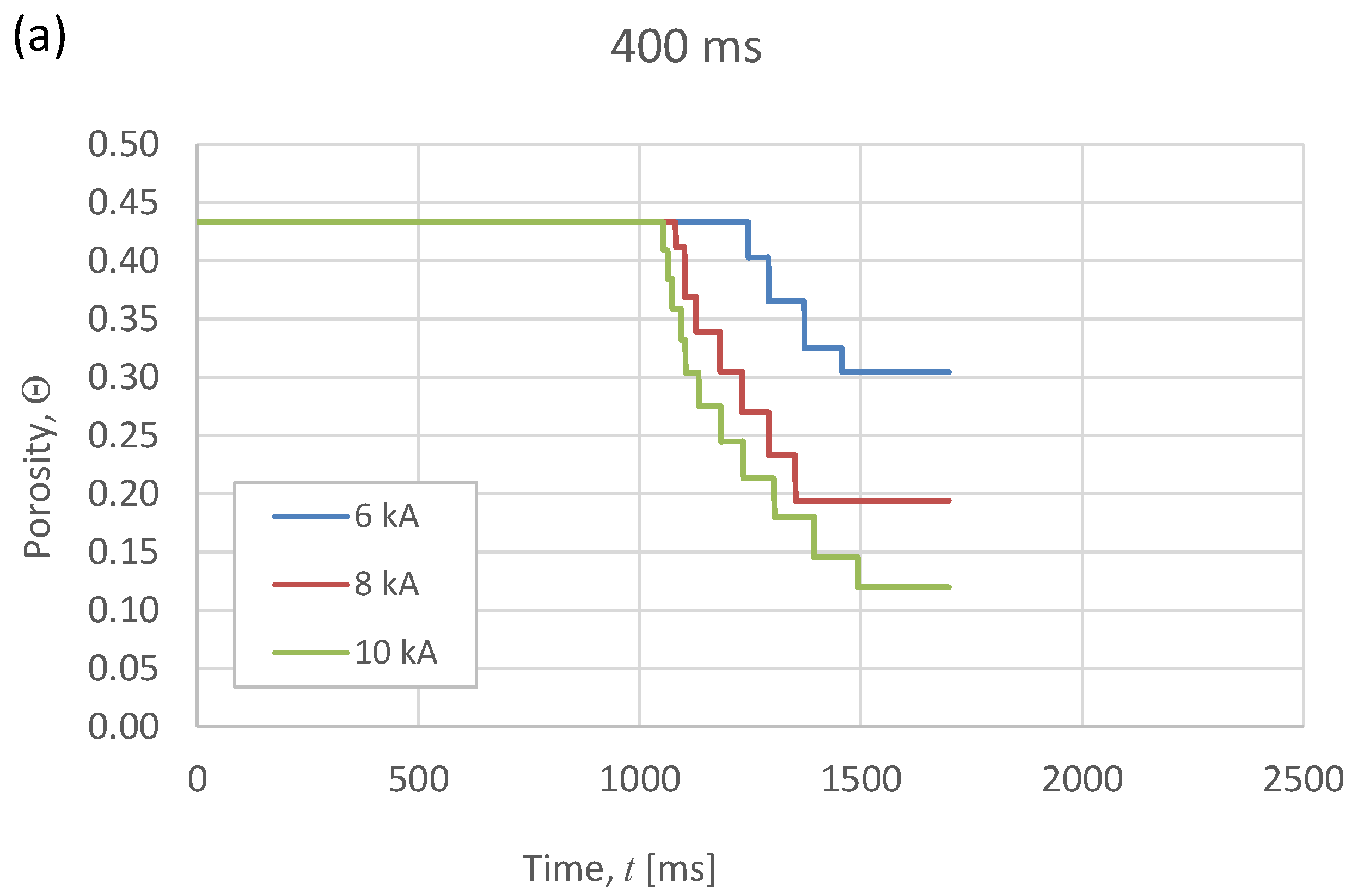
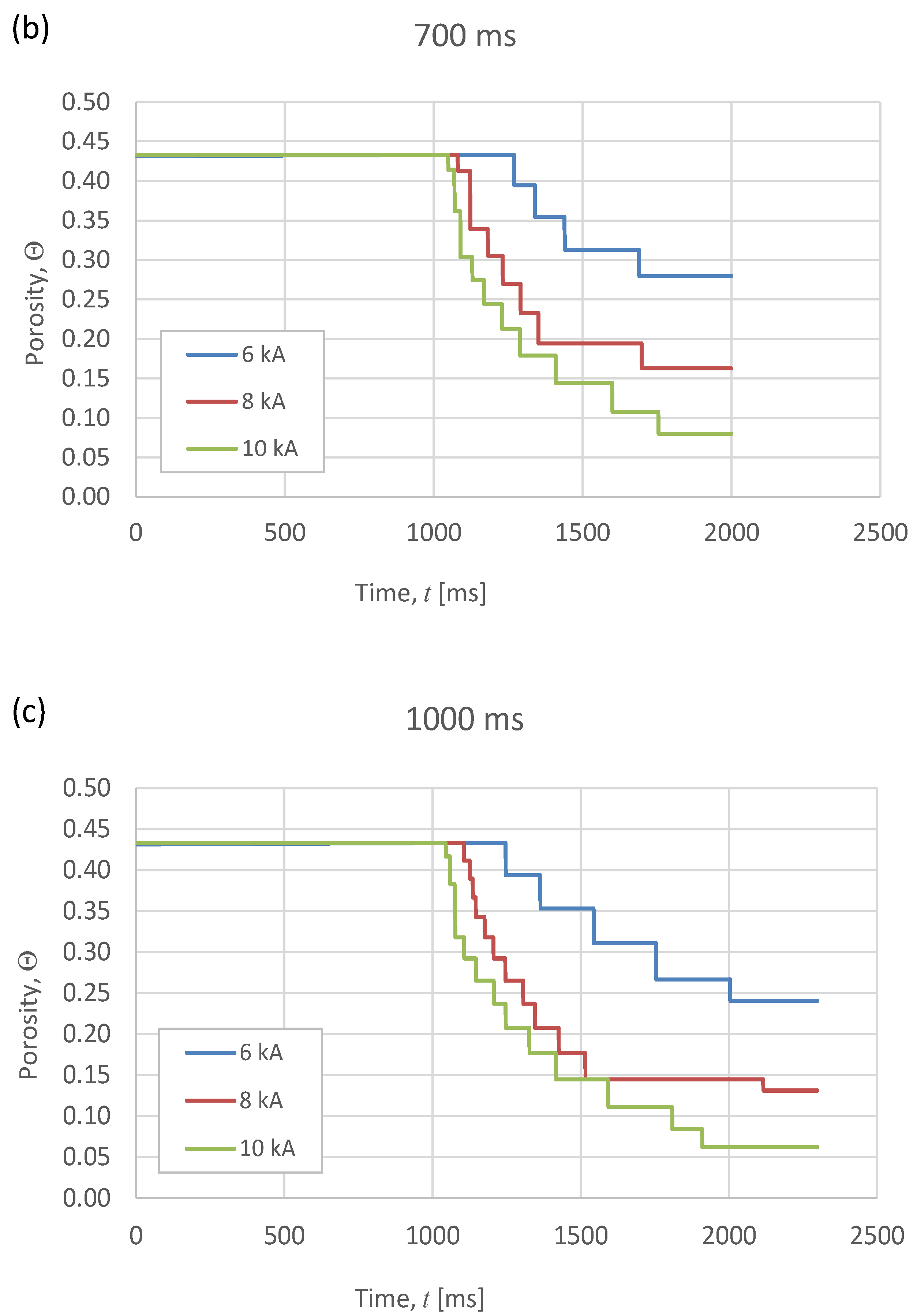
Metals 08 00426 g005
Figure 6. Evolution of the global porosity Θ, as a function of the current intensity, for different heating times: (a) 400 ms, (b) 700 ms, and (c) 1000 ms. The intensity starts passing through the specimen after 1000 ms and stops 300 ms before the end of the process.
Metals 08 00426 g006aMetals 08 00426 g006b
Figure 7. Compacts final porosity (ΘF) versus (a) intensity and (b) heating time, for the different MF-ERS experiments. The continuous lines in both graphs represent the trend of the whole data cloud. The discontinuous lines in (b) describe the trends of experiences carried out with the same current intensity.
Metals 08 00426 g007
Figure 8. Compacts final porosity (ΘF) versus released specific thermal energy (STE) for the different MF-ERS experiments. The continuous line describes the trend of the whole data cloud, whereas the discontinuous lines correspond to the trends of experiences carried out with the same current intensity.
Metals 08 00426 g008
Figure 9. (a) Macrograph, and micrographs showing the porosity distribution at (b) the corner and (c) center of a diametrical section of a compact conventionally consolidated.
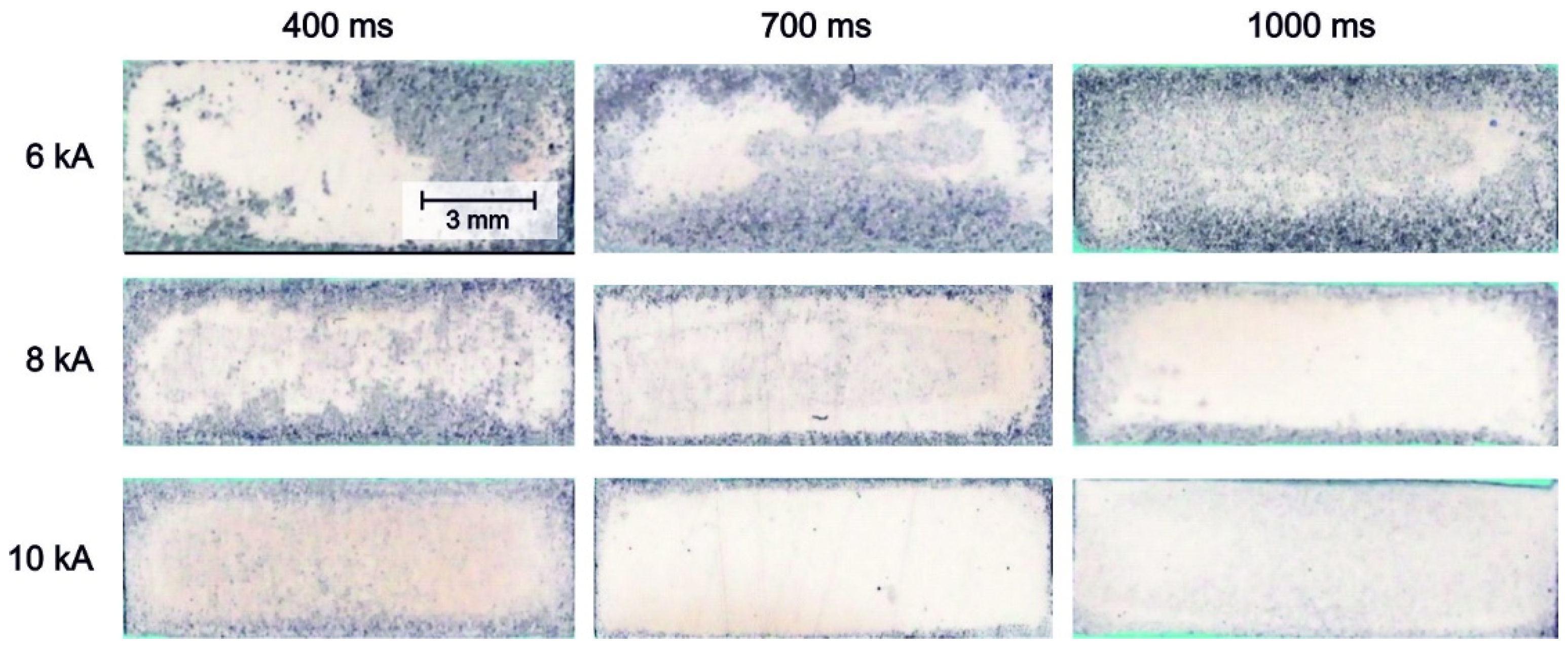
Metals 08 00426 g009
Figure 10. Porosity distribution in MF-ERS Fe compacts. White areas (more reflecting) indicate a lower porosity content.
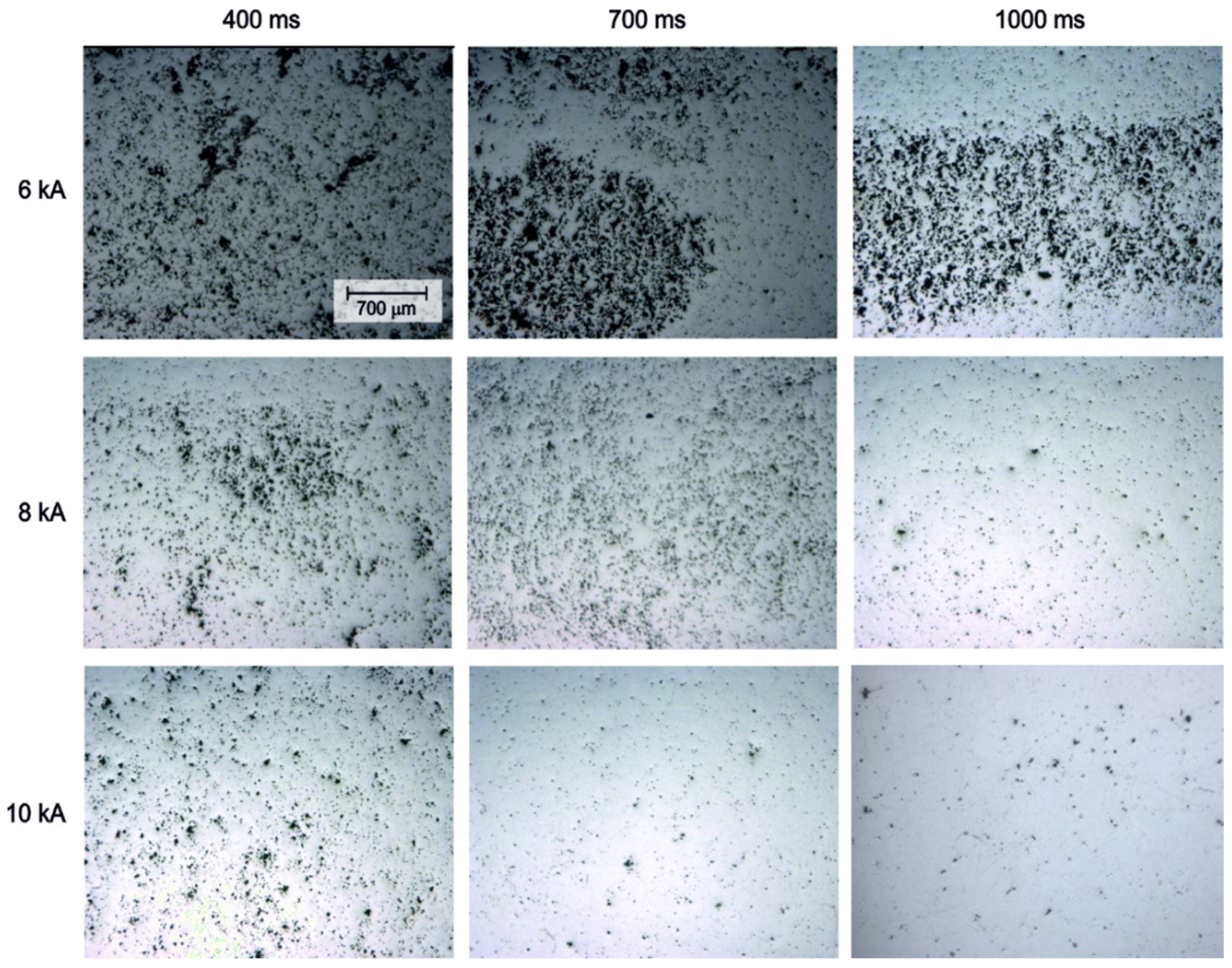
Metals 08 00426 g010
Figure 11. Micrographs showing the porosity distribution in a corner of diametrical sections of MF-ERS compacts consolidated under different conditions.
Metals 08 00426 g011
Figure 12. Micrographs showing the porosity distribution at the center of diametrical sections of MF-ERS compacts consolidated under different conditions.
Metals 08 00426 g012
Table 1. Values of the compacts final porosity (ΘF) in function of the intensity (in kA) and heating time (in ms) for the different MF-ERS experiments.
Heating Time
400 ms700 ms1000 ms
Intensity6 kA0.300.280.24
8 kA0.190.160.13
10 kA0.120.080.06
Table 2. Values of the STE (in kJ/g) in function of the intensity (in kA) and heating time (in ms) for the different MF-ERS experiments
Heating Time
400 ms700 ms1000 ms
Intensity6 kA0.350.470.59
8 kA0.430.600.77
10 kA0.530.721.02

