Abstract
Electric power production continues to increase as the industry advances, and the demand for high-capacity batteries for efficient operation of the electric power produced is higher than ever before. Si has been attracting a great deal of attention recently as an anode electrode material because of its high theoretical capacity. However, it suffers from significant capacity-loss, resulting from the volume-expansion of Si during charge and discharge cycles. Inspired by the multiscale structures commonly found in nature, we attempt to solve this problem by patterning the surface of the Cu current-collector. To this end, we develop a direct, one-step method using laser patterning to manufacture a multiscale structure on the surface of the current-collector. The inherent exfoliation characteristic of the Cu current-collector allows the spontaneous formation of the multiscale structure while being irradiated with a laser. A micro/nano structure, with a different surface area, is fabricated by varying the laser output at three levels, and the batteries prepared with the fabricated Cu current-collector are tested to evaluate their charge-discharge characteristics and electrochemical impedance. The results show that the multiscale structure reduces mechanical stress. The initial capacity of the Cu current-collector is proportional to the laser output, and the initial capacity of the coin cell prepared with the Cu current-collector, fabricated at the highest laser output, is 396.7% higher than that of the coin cell prepared with a bare Cu current-collector. The impedance is inversely proportional to the laser output. The charge transfer resistance of the coin cell prepared with the Cu current-collector and irradiated with the highest laser output is 190.2% lower than that of the coin cell prepared with the bare Cu current-collector.
1. Introduction
Lithium-ion batteries are among the most dominant batteries of current power sources [1,2]. Lithium-ion batteries are characterized by high power density, energy density, and longer lifespan in comparison to other power sources. Along with the rapid technological advances, the demand for electrical products with energy-efficient lithium-ion batteries has increased, such as electric vehicles and energy storage devices [3,4]. To meet the industrial demand for high-capacity batteries for these applications, extensive research on materials with excellent energy storage characteristics is ongoing. The performance of batteries is essentially determined by the performance of the three core components: The cathode, anode, and electrolyte. The capacity of cathodes has already reached the theoretical limit, and much effort for further improvement is being directed to alternative materials for the current graphite-based anodes, particularly Si-based anodes [5,6,7,8,9]. Interest in Si-based anodes originates from both their 10-fold higher theoretical capacity than that of commercial graphite-based batteries, and their 0.5 V lower operation voltage than that of commercial Li/Li+ batteries [10,11]. However, Si has a lower conductivity than graphite, and volume-expansion during charge-discharge cycles causes the pulverization of Si and the consequent degradation of the electric connection between the electrodes. This volume-expansion is the major source of capacity-loss during the electrochemical reactions [12,13,14,15]. To solve this problem, Si nanotubes and nanostructures have been developed to prevent crack-formation by providing buffering space for the expansion of Si [16,17,18]. As another promising solution, surface processing of the electrodes has become a mainstream method to increase battery capacity. Above all, three-dimensional (3D) nanostructured electrodes are being developed to accommodate the volume-expansion of Si on the current-collector by increasing the surface area, which would decrease the pulverization of Si deposited on the surface, thereby facilitating the diffusion and transport of lithium ions [19,20,21]. However, these technologies are difficult to apply in the battery production process, and because of the high processing cost, they are not suited to mass-production.
Meanwhile, laser processing is a well-established process, widely used in various industries. There are numerous applications found in material, chemical, and electronic industries. Laser processing is capable not only of engraving a large area rapidly while delivering low-cost and convenient implementation, but also of producing highly precise and sustainable marks on numerous materials. In this paper, laser processing was employed to enlarge the surface area so as to improve battery efficiency by creating a multiscale structure on the electrodes. In contrast with other methods for increasing the surface area, laser processing is appropriate for the current industry owing to the size of the machine and the simple process.
In the current project, the micro/nano-structure on the surface of the Cu current-collector was fabricated via the laser patterning method. As the energy of the laser reached the Cu surface, it induced the evaporation of Cu in the Cu current collector, thereby leading to the spontaneous formation of a multiscale structure in one step. In order to evaluate whether the multiscale Cu current-collector is indeed capable of reducing the mechanical stress resulting from volume-expansion, Si particles were deposited on the Cu current-collector using RF-magnetron sputtering. The batteries prepared with the fabricated Cu current-collector were tested for their ability to suppress the volume-expansion of Si and improve stability during charge-discharge cycles. Three multiscale Cu current-collectors were produced by varying the laser output at three levels, and they were compared with a bare Cu current-collector. In the charge-discharge cycle and the impedance analysis, the lithium-ion batteries prepared with the Cu current-collector at the highest laser output showed the highest cycle stability and the lowest impedance. Improved battery capacity and capacity retention could be achieved with a simple and rapid laser irradiation process, and the method described in this study would be suitable for industrial applications.
2. Experimental
A single-mode nanosecond pulsed HY-FM20 laser with an output power of 10, 20, and 30 W was used in this study to create a multiscale structure on the Cu current-collector surface. The HY-FM20 laser (model YLP-V2) was made by IPG Lasers GmbH, from Germany. The laser beam, with a central emission wavelength of 1064 nm and a maximum pulse repetition rate of 1000 kHz, was delivered by three totally-reflective mirrors, a beam expander, an XY-axes galvano scanner, and a telecentric focusing lens. The beam spot size at the focal point was about 10 μm. Sample movement was generated by an XYZ-axes movable stage with a ball-screw mechanism. Figure 1 shows a schematic diagram of the nanosecond pulsed HY-FM20 laser processing apparatus with an XY-axes galvano scanner.
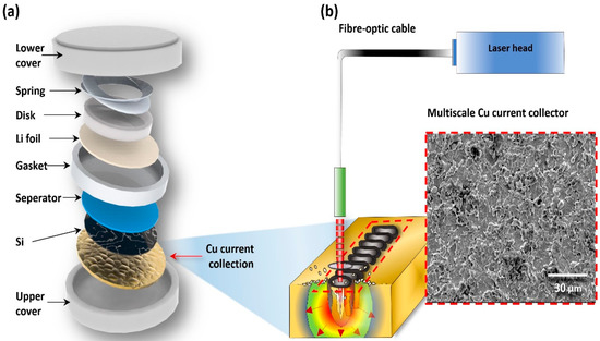
Figure 1.
Laser one-step structuring to create a textured surface: (a) a typical setup for a coin-type cell battery; (b) a schematic diagram of nanosecond laser and SEM images of the Cu surface after laser irradiation.
The Si thin-film electrodes on the patterned Cu foils were formed using an RF magnetron sputtering deposition method with a Si sputtering target (99.999%, LTS chemical, New York, USA) under an Ar atmosphere (30 SCCM). The sputtering process was performed with an RF power of 60 W for 90 min at a working pressure of 1.1 × 10⁻² torr.
The electrochemical properties of the Si electrodes were evaluated using coin-type cells (size 2032, Hohsen Corporation, Osaka, Japan). The assembly for the cells was carried out in an Ar-filled glove box (<5 ppm of H2O and O2). The as-prepared Si electrodes, cut with a diameter of 13 Ф and lithium foil, were used as working- and counter-electrodes, respectively. The porous polyethylene (Celgard 2400, Hohsen Corporation, Osaka, Japan) and 1.1 M LiPF6 dissolved in ethylene carbonate (EC): dimethyl carbonate (DEC) = 1:1 vol % were used as a separator and electrolyte, respectively. The charging/discharging characteristic curves of the assembled cells were obtained using a multi-channel battery tester (WBCS3000L, Wonatech Co., Seoul, Korea) at 25 °C. The electrochemical impedance spectroscopy (EIS) was performed using an electrochemical analyzer (Eco Chemie, Autolab, Utrecht, The Netherlands) at an applied voltage of 5 mV in the frequency range of 10 mHz–100 kHz.
Structural characterization techniques were performed using a nanosurface 3D optical profiler (NV-E1000; Nano System Co. Ltd., Daejeon, Korea). The nanosurface 3D optical profiler has a vertical scanning range (180 μm), horizontal scanning range (65 to 650 μm), horizontal resolution (0.2 to 4 μm), vertical resolution (WSI 0.5 nm and PSI 0.1 nm), and different types of lenses (×10, ×50, ×100).
3. Results and Discussion
Nature has evolved ways to texture a surface to substantially increase its surface area using micro/nano structures. Various micro/nano structures derived from nature are being used for various industrial applications. Multiscale structures are used to increase the surface area for cell growth in the biomedical field and to create a superhydrophobic surface. In tribology, multiscale structures are used to modify surface friction properties. A surface area can be increased by various methods, including grit-blasting or chemical etching. Among these techniques, we used a laser processing method to increase the surface area of the Cu current-collectors. In the laser processing, there is no physical contact on the Cu current-collector surface during fabrication; this method features high reproducibility and low contamination. Moreover, it is a more economical method to produce micro/nano structures than the e-beam evaporation method that is currently used to create 3D patterns on Cu current-collector surfaces.
Figure 1 shows a schematic of the overall manufacturing process using one-step laser irradiation to create a multiscale structure on the Cu current-collector surface. A 30 mm × 30 mm area on the Cu current-collector surface was irradiated by the laser. The operation speed, width of the laser, and laser moving speed were set to 2000 mm/s, 0.01 mm, and 500 mm/min, respectively, to determine the effect of laser intensity on battery performance. Laser irradiation was carried out at three levels: 10, 20, and 30 W. By mimicking the multiscale structure found in nature, we intended to improve the performance of lithium-ion batteries by using a simple one-step fabrication process that can generate a micro/nano structure to alleviate the mechanical structure on the Cu current-collector surface.
Figure 2 shows the surface analysis data of the four Cu current-collectors (one bare Cu current-collector and three Cu current-collectors fabricated by laser). Figure 2a,e,i,m show 3D images of the Cu current-collectors in the following order: The bare Cu current-collector surface and the Cu current-collector surfaces fabricated with 10, 20, and 30 W lasers. These results qualitatively show that the surface roughness could be increased with increased laser power. Figure 2b,f,j, and n show the Field Emission Scanning Electron Microscopy (FESEM) images of the Cu current-collector surfaces, which correspond to Figure 2a,e,i,m, respectively. The right figure of the 3D images are 500× SEM images, respectively. While in Figure 2b the surface is smooth with little void space, the void space per unit area created by the micro/nano structure increases gradually in Figure 2f,j,n. Figure 2c,g,k,o show the line scan profiles of the Cu current-collectors extracted at three different spots along both the X- and Y-axes. The upper and bottom graphs in these Figures are the line scan profiles along the X- and Y-axis, respectively. The ripples are denser along the Y-axis than they are along the X-axis, along which the laser is moved. This is because of the laser-induced melting and resultant smoothing of the Cu surface. While the surface of the bare Cu current-collector was relatively straight and flat (Figure 2c), as the laser intensity increased, the ripples became much more noticeable, and the density and extent increased (Figure 2g,k,o). The ripples represent a hierarchical structure consisting of a micro/nano structure similar to that found in nature. One example of such is the number of micro-sized alveoli in the lungs, which maximize the surface area for gas exchange. Lastly, Figure 2 d,h,l, and p show the surface roughness averages (Ra) of the regions extracted from Figure 2c,g,k,o, respectively. A higher Ra value indicates a higher degree of roughness, which translates into a larger surface area. The bar graph and error bar of Ra in these figures represent the average and standard errors along the line-scan profiles shown in red, green, and blue in Figure 2c,g,k,o, respectively. The Ra values measured in Figure 2d are 0.137 ± 0.017 μm in full image Ra value, where 0.126 ± 0.011 μm and 0.151 ± 0.02 μm along the X- and Y-axis, respectively. In comparison with the bare Cu current-collector (Figure 2d), the average RA of a laser-irradiated Cu current-collector surface (Figure 2h) was increased by 196% and 256% along the X- and Y-axis, respectively. The Ra of the roughest surface (Figure 2p) was 685% and 789% higher along the X- and Y-axis than those of the bare Cu current-collector (Figure 2d). Cu in the Cu current-collector evaporates owing to the high heat of the laser ablation and then cools off rapidly in air before being deposited again on the surface of the Cu current-collector. As the surface area is increased due to the fabricated nanostructure, Ra values increase, which clearly demonstrates that the Cu current-collector surface area is increased with the laser power. These results indicate that a higher output is required to generate more void space on the surface, which would accommodate the volume expansion resulting from electrochemical reactions.

Figure 2.
Fabrication of a bio-inspired Si electrode. The bare Cu current-collector: (a) Three-dimensional (3D) image; (b) SEM images; (c) line scan profiles in the X and Y directions; and (d) surface roughness averages (Ra) measured in (c); the Cu current-collector after the one-step method by the 10 W power laser process: (e) 3D image taken by surface profiler; (f) SEM images; (g) line scan profiles in the X and Y directions; and (h) surface roughness averages (Ra) measured in (g); the Cu current-collector after the one-step method by the 20 W power laser process: (i) 3D image taken by surface profiler; (j) SEM images; (k) line scan profiles in the X and Y directions; and (l) surface roughness averages (Ra) measured in (k); the Cu current-collector after the one-step method by the 30 W power laser process: (m) 3D image taken by surface profiler; (n) SEM images; (o) line scan profiles in the X and Y directions; and (p) surface roughness averages (Ra) measured in (o).
Figure 3 shows the simulated mechanical stress applied to the Si layer deposited on the bare Cu current-collector and the laser-irradiated Cu current-collectors. For this simulation, a multiscale model was developed to simulate the roughness of the bare and laser-irradiated Cu current-collectors, depending on the laser power. The COMSOL Multiphysics (ver. 5.3) program was used for the simulation. The simulated area was set at 1 cm × 1 cm (1 cm2), and the relative roughness per unit area of the bare Cu current-collector, 10 W-Cu current-collector, 20 W-Cu current-collector, and 30 W-Cu current-collector was set at 0, 1, 2, and 3, respectively. The inputs of this simulation are surface area and the output represents the stress when the silicon expands under the input conditions. Figure 3a–d in Column 1 shows the simulated surface of the four models. The surface areas per unit area of the bare Cu current-collector, 10 W-Cu current-collector, 20 W-Cu current-collector, and 30 W-Cu current-collector are 1.0, 1.0215, 1.0824, and 1.281, respectively. According to these simulation results, the increase of the surface area per unit area with the micro/nano structure on the surface is responsible for the stress relief of Si expansion. Figure 3a–d in Columns 2, 3, and 4 are the 3D images showing both the volume-expansion of the Si-layer deposited on the 10, 20, and 30 W Cu current-collectors during lithiation and the stress distribution in the Si-layer extracted from three locations along the X-axis. In the 3D images, red and blue indicate the regions under high and low mechanical stress, respectively. The mechanical stress is expressed in J/cm3. Figure 3a in Column 2 shows that the Si layer deposited on the flat Cu current-collector has no void space to accommodate the expanding Si particles. Consequently, the Si particles begin to push each other out, increasing the thickness of the Si-layer. The increasing mechanical stress per unit volume is noted in the red regions of the 3D images. In contrast, the micro/nano structure generated by the laser creates void space in the Cu current-collector surface that is sufficient to allow the expansion of the deposited Si-layer without forming cracks (Figure 3b–d). The reducing stress is represented in the greater blue and lesser red regions in Figure 3b–d in sequence. The stress per unit area shown in Figure 3a–d, which is the average stress in three spots extracted along the X-axis, is 160 ± 10, 130 ± 10, 90 ± 10, and 50 ± 10 N/cm2, respectively. These results in sequence quantitatively demonstrate the reduction of the mechanical stress resulting from the volume-expansion of the Si-layer.

Figure 3.
Simulation analysis of the mechanical stress applied to the Si layer when the Si layer undergoes volume-expansion: (a) row 1 (the bare Cu current-collector model): Surface area (SA) per unit area, 3D image of the volume-expansion during lithiation of the deposited Si layer, and stress distribution of the Si layer extracted from three locations along the X-axis; (b) row 2 (the Cu current-collector model irradiated with 10 W): SA per unit area, 3D image of the volume-expansion during lithiation of the deposited Si layer, and stress distribution of the Si layer extracted from three locations along the X-axis; (c) row 3 (the Cu current-collector model irradiated with 20 W): SA per unit area, 3D image of the volume-expansion during lithiation of the deposited Si layer, and stress distribution of the Si layer extracted from three locations along the X-axis; (d) row 4 (the Cu current-collector model irradiated with 30 W): SA per unit area, 3D image of the volume-expansion during lithiation of the deposited Si layer, and stress distribution of the Si layer extracted from three locations along the X-axis.
Overall, the data presented in Figure 3 suggest that the laser irradiation directly forms a micro/nano structure on the Cu current-collector surface, and the resulting void space reduces the build-up of mechanical stress. The volume-expansion of the Si-layer increases the distance between the electrodes. This results in the deterioration of electric connections during the electrical chemical reactions, eventually leading to battery performance degradation. The simulation results demonstrate that the multiscale structure formed on the Cu current-collector surface could alleviate the mechanical stress, which is critical to improving battery performance.
Figure 4 shows the charge-discharge curves of the lithium-ion batteries prepared with the bare Cu current-collector and the laser-irradiated Cu current-collectors. Si was used as the electrode material, and charging and discharging were carried out at a current density of 6 A g−1 in the range of 0.01 to 1.50 V. Figure 4a shows the charge–discharge curve of the lithium-ion battery made from the bare Cu current-collector. The initial discharge capacity and the capacity after 100 cycles were 949 and 221 mAh g−1, respectively. The initial coulombic efficiency (CE) was very low (3%), which is a common phenomenon in the activation process of Si electrodes. As the number of cycles increases, the CE continues to increase, and it reaches 90% after 50 cycles. Figure 4b shows the charge–discharge of the lithium-ion battery prepared with the 10 W-Cu current-collector. The initial discharge capacity and the capacity after 100 cycles were 2013 and 225 mAh g−1, respectively. The initial CE was about 8%, and it maintained 90% after 50 cycles. Figure 4c shows the charge-discharge characteristics of the lithium-ion battery prepared with the 20 W-Cu current-collector. The initial discharge capacity and the capacity after 100 cycles were 2799 and 291 mAh g−1, respectively. The CE after the first cycle was 17%, and it continued to increase up to 95% after 50 cycles. The higher initial discharge capacity in Figure 4c than in Figure 4b suggests that the laser irradiation directly creates a micro/nano structure on the Cu current-collector surface, which in turn creates void space in the Si-layer, which is used as the active anode material. Figure 4d is the charge-discharge graph of the lithium-ion battery prepared with the 30 W-Cu current-collector. The initial discharge capacity and the capacity after 100 cycles were 3763 and 315 mAh g−1, respectively. The initial CE of 17% continued with cycles and maintained 90% after 30 cycles. Compared to Figure 4c, the initial discharge capacity increased by 1000 mAh g−1. Again, the higher initial discharge capacity indicates that the stronger laser power is more efficient to fabricate the multiscale structure on the Cu current-collector surface, more efficiently reducing the mechanical stress caused by the volume-expansion. On the other hand, the CE was reduced by 5%, suggesting the trade-off to be considered when high laser power is desired.

Figure 4.
Charge-discharge graph when the bare Cu current-collector and Cu current-collector irradiated with a laser are used as lithium ion batteries. The charge and discharge on the Cu current-collector: (a) The bare collector; and the collectors irradiated with a laser of (b) 10 W; (c) 20 W; and (d) 30 W.
Figure 5 comprehensively summarizes the initial discharge capacity and capacity retention to analyze and compare the results of 100 cycles (Figure 4a–d). The insets in Figure 5 show the discharge capacity of Figure 4a–d for the first 60–100 cycles. The Lithium-ion batteries prepared with the laser-irradiated Cu current-collectors showed superior initial capacity and capacity retention to the lithium-ion battery prepared with the bare Cu current-collector. This performance improvement can be attributed to the increased surface area of the Cu current-collectors by laser irradiation.
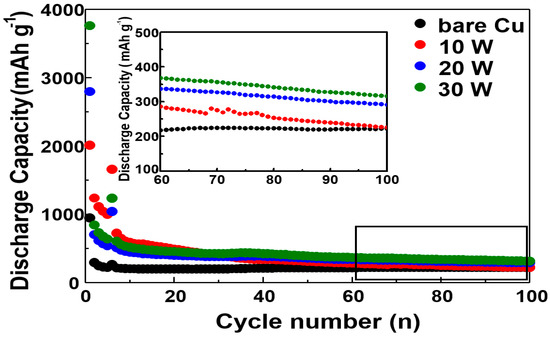
Figure 5.
Comprehensive comparison of the initial discharge capacity and capacity retention of Figure 4a–d.
The results in Figure 4 and Figure 5 show that a higher laser power is desirable to increase the initial capacity by simply generating a denser micro/nano structure; however, the CE was lowered by increasing the laser power, suggesting that these two performance parameters should be balanced, depending on specific applications. The large surface area of the bio-inspired multiscale Cu current-collector may facilitate the contact of the atoms on the Cu current-collector surface and the Si atoms on the anode. As the contact between the atoms increases, the resulting electrostatic attraction strengthens the contact force, which narrows the gap between the Cu current-collector and the Si-layer and facilitates lithiation in lithium-ion batteries [22,23]. In nature, the gecko is a representative example of utilizing increased surface area for strong adhesion. The Gecko has soles packed with micro/nano structures to efficiently increase the contact area between atoms, resulting in increased van der Waals force, which allow it to adhere to a surface [24,25].
Figure 6 shows the impedance analysis results of the lithium-ion batteries prepared with the 10 W-, 20 W-, and 30 W-Cu current-collector for the first 5 and 100 cycles. AC impedance analysis is a method of modeling an electrochemical reaction between the two electrodes in batteries, and it models the electrochemical reaction as an electric circuit to obtain information on the charge transfer resistance (Rct). Figure 6a shows the Rct of the bare Cu current-collector. The Rct was 405.73 and 204.85 Ω after 5 and 100 cycles, respectively. Figure 6b shows the Rct of the Cu current-collector irradiated by 10 W laser. The Rct was 455.85 and 258.80 Ω after 5 and 100 cycles, respectively. Figure 6c shows the Rct of the Cu current-collector irradiated by 20 W laser. In this case, the Rct value was 640.21 and 237.16 Ω after 5 and 100 cycles, respectively. Figure 6d shows the Rct of the Cu current-collector irradiated by 30 W laser. The Rct value was 448.76 Ω and 213.30 Ω after 5 and 100 cycles, respectively.

Figure 6.
Data obtained by analyzing the impedance of the bare Cu current-collector and Cu current-collectors irradiated with laser after (5 and 100) cycles. Charge transfer resistance of (a) the bare Cu current-collector; and of the Cu current-collector irradiated with (b) 10 W; (c) 20 W; and (d) 30 W.
These results show that the resistance in the impedance analysis decreases after 100 cycles, as the average roughness increases with the laser’s power. This is because the increasing surface area, equivalent to the increasing surface roughness, improves the stability of the batteries by suppressing crack formation due to volumetric expansion.
4. Conclusions
Rapid technological development triggered by the 4th Industrial Revolution is reshaping energy fields, including ubiquitous energy, energy harvesting, and renewable energy. As a critical element to support this ongoing technological development, battery technology is attracting unprecedented attention. High-capacity and stable batteries are crucial for the realization of large-capacity industrial energy-storage devices. However, the theoretical capacity of graphite, which is the most commonly-used active anode material, is only 372 mAh g−1, which is far lower than the capacity required for industrial applications. For this reason, Si is of particular interest, due to its high theoretical capacity of 4200 mAh, and much effort is ongoing to use Si as an active electrode material. Despite its high theoretical capacity, the degradation of electrical connection due to volume-expansion (about 400%) and the pulverization of Si cause substantial capacity-loss.
To offer a viable solution, we attempted, using laser irradiation, to develop a bio-inspired Cu current-collector that was fabricated to have a surface mimicking a natural multiscale structure. The CE of the coin-type half-cell prepared with the laser-irradiated Cu current-collectors was maintained at a 90% level after the initial activation process, and the laser irradiation also increased the battery capacity to 3763 mAh g−1, which was 2814 mAh g−1 higher than the capacity of the battery prepared with the bare Cu current-collector (396.52% improvement).
This improvement was attributed to the multiscale micro/nano structure formed on the Cu current-collector surface. In one step, laser irradiation efficiently created a micro/nano structure on the Cu current-collector through surface explosion, rapidly increasing the Cu current-collector surface area. The resulting larger surface area facilitates the contact between Si and the atoms on the Cu current-collector, and it strengthens the electrostatic force between them. The electrostatic force enhances the adhesion between the Si layer deposited on the Cu current-collector and the Cu current-collector, which facilitates charge transfer by narrowing the gap between the layers, while improving endurance against the repeated volume-expansion of the Si-layer. By providing sufficient void space to accommodate the volumetric expansion of the Si-layer, the micro/nano structure created on the Cu current-collector prevents the pulverization of the Si particles, which results in a poor electric contact between the active particles and the resulting separation of the Si-layer from the Cu current-collector surface. In this study, we proposed a simple and inexpensive method to improve battery capacity, which can readily be applied to industrial applications.
Author Contributions
W.-G.B., K.-Y.S., and K.-W.P. conceived and designed the research. J.-Y.S. conducted the experiments and prepared the draft manuscript. S.-H.M., M.-C.K., S.-J.K., S.-B.H., C.-H.L., J.-E.K., H.-J.K., and J.J. performed data analysis and participated in the discussions.
Acknowledgments
This work was supported by the Soongsil University Research Fund of 2017. This work was also supported from the NRF of Korea by the Grant (NRF-2016R1D1A1B03934431) provided to W.G. Bae.
Conflicts of Interest
The authors declare no conflict of interest.
References
- Shin, S.-M.; Lee, D.-W.; Wang, J.-P. Fabrication of nickel nanosized powder from linio2 from spent lithium-ion battery. Metals 2018, 8, 79. [Google Scholar] [CrossRef]
- Kang, G.-H.; Lee, K.-W.; Kwon, K.; Song, J. The effects of incorporated Sn in resynthesized Ni-rich cathode materials on their lithium-ion battery performance. Metals 2017, 7, 395. [Google Scholar] [CrossRef]
- Lee, H.; Jeong, J.; Park, Y.-I.; Cha, S.W. Energy management strategy of hybrid electric vehicle using battery state of charge trajectory information. Int. J. Precis. Eng. Manuf. Green Technol. 2017, 4, 79–86. [Google Scholar] [CrossRef]
- Choi, J.; Jeong, J.; Park, Y.-I.; Cha, S.W. Evaluation of regenerative braking effect for e-rev bus according to characteristic of driving cycle. Int. J. Precis. Eng. Manuf. Green Technol. 2015, 2, 149–155. [Google Scholar] [CrossRef]
- Goodenough, J.B.; Park, K.-S. The Li-ion rechargeable battery: A perspective. J. Am. Chem. Soc. 2013, 135, 1167–1176. [Google Scholar] [CrossRef] [PubMed]
- Kang, K.; Meng, Y.S.; Bréger, J.; Grey, C.P.; Ceder, G. Electrodes with high power and high capacity for rechargeable lithium batteries. Science 2006, 311, 977–980. [Google Scholar] [CrossRef] [PubMed]
- Whittingham, M.S. Lithium batteries and cathode materials. Chem. Rev. 2004, 104, 4271–4302. [Google Scholar] [CrossRef] [PubMed]
- Etacheri, V.; Marom, R.; Elazari, R.; Salitra, G.; Aurbach, D. Challenges in the development of advanced Li-ion batteries: A review. Energy Environ. Sci. 2011, 4, 3243–3262. [Google Scholar] [CrossRef]
- Islam, M.; Ur, S.-C.; Yoon, M.-S. Improved performance of porous lifepo 4/c as lithium battery cathode processed by high energy milling comparison with conventional ball milling. Curr. Appl. Phys. 2015, 15, 541–546. [Google Scholar] [CrossRef]
- Munaò, D.; Valvo, M.; Van Erven, J.; Kelder, E.M.; Hassoun, J.; Panero, S. Silicon-based nanocomposite for advanced thin film anodes in lithium-ion batteries. J. Mater. Chem. 2012, 22, 1556–1561. [Google Scholar] [CrossRef]
- Park, C.-M.; Kim, J.-H.; Kim, H.; Sohn, H.-J. Li-alloy based anode materials for li secondary batteries. Chem. Soc. Rev. 2010, 39, 3115–3141. [Google Scholar] [CrossRef] [PubMed]
- Lee, S.W.; McDowell, M.T.; Choi, J.W.; Cui, Y. Anomalous shape changes of silicon nanopillars by electrochemical lithiation. Nano Lett. 2011, 11, 3034–3039. [Google Scholar] [CrossRef] [PubMed]
- Liu, X.H.; Zhang, L.Q.; Zhong, L.; Liu, Y.; Zheng, H.; Wang, J.W.; Cho, J.-H.; Dayeh, S.A.; Picraux, S.T.; Sullivan, J.P. Ultrafast electrochemical lithiation of individual Si nanowire anodes. Nano Lett. 2011, 11, 2251–2258. [Google Scholar] [CrossRef] [PubMed]
- Liu, X.H.; Zheng, H.; Zhong, L.; Huang, S.; Karki, K.; Zhang, L.Q.; Liu, Y.; Kushima, A.; Liang, W.T.; Wang, J.W. Anisotropic swelling and fracture of silicon nanowires during lithiation. Nano Lett. 2011, 11, 3312–3318. [Google Scholar] [CrossRef] [PubMed]
- Liu, X.H.; Zhong, L.; Huang, S.; Mao, S.X.; Zhu, T.; Huang, J.Y. Size-dependent fracture of silicon nanoparticles during lithiation. ACS Nano 2012, 6, 1522–1531. [Google Scholar] [CrossRef] [PubMed]
- Park, M.-H.; Kim, M.G.; Joo, J.; Kim, K.; Kim, J.; Ahn, S.; Cui, Y.; Cho, J. Silicon nanotube battery anodes. Nano Lett. 2009, 9, 3844–3847. [Google Scholar] [CrossRef] [PubMed]
- Wen, Z.; Lu, G.; Mao, S.; Kim, H.; Cui, S.; Yu, K.; Huang, X.; Hurley, P.T.; Mao, O.; Chen, J. Silicon nanotube anode for lithium-ion batteries. Electrochem. Commun. 2013, 29, 67–70. [Google Scholar] [CrossRef]
- Wu, H.; Cui, Y. Designing nanostructured si anodes for high energy lithium ion batteries. Nano Today 2012, 7, 414–429. [Google Scholar] [CrossRef]
- Liu, B.; Soares, P.; Checkles, C.; Zhao, Y.; Yu, G. Three-dimensional hierarchical ternary nanostructures for high-performance Li-ion battery anodes. Nano Lett. 2013, 13, 3414–3419. [Google Scholar] [CrossRef] [PubMed]
- Shin, H.C.; Liu, M. Three-dimensional porous copper–tin alloy electrodes for rechargeable lithium batteries. Adv. Funct. Mater. 2005, 15, 582–586. [Google Scholar] [CrossRef]
- Kim, G.; Jeong, S.; Shin, J.-H.; Cho, J.; Lee, H. 3D amorphous silicon on nanopillar copper electrodes as anodes for high-rate lithium-ion batteries. ACS Nano 2014, 8, 1907–1912. [Google Scholar] [CrossRef] [PubMed]
- Dong, A.; Wang, Y.; Tang, Y.; Ren, N.; Yang, W.; Gao, Z. Fabrication of compact silver nanoshells on polystyrene spheres through electrostatic attraction. Chem. Commun. 2002, 350–351. [Google Scholar] [CrossRef]
- Zhou, X.; Yin, Y.X.; Wan, L.J.; Guo, Y.G. Self-assembled nanocomposite of silicon nanoparticles encapsulated in graphene through electrostatic attraction for lithium-ion batteries. Adv. Energy Mater. 2012, 2, 1086–1090. [Google Scholar] [CrossRef]
- Autumn, K.; Liang, Y.A.; Hsieh, S.T.; Zesch, W.; Chan, W.P.; Kenny, T.W.; Fearing, R.; Full, R.J. Adhesive force of a single gecko foot-hair. Nature 2000, 405, 681–685. [Google Scholar] [CrossRef] [PubMed]
- Geim, A.K.; Dubonos, S.; Grigorieva, I.; Novoselov, K.; Zhukov, A.; Shapoval, S.Y. Microfabricated adhesive mimicking gecko foot-hair. Nat. Mater. 2003, 2, 461–463. [Google Scholar] [CrossRef] [PubMed]
© 2018 by the authors. Licensee MDPI, Basel, Switzerland. This article is an open access article distributed under the terms and conditions of the Creative Commons Attribution (CC BY) license (http://creativecommons.org/licenses/by/4.0/).