Die Defects and Die Corrections in Metal Extrusion

Abstract
:1. Introduction
1.1. Current Work
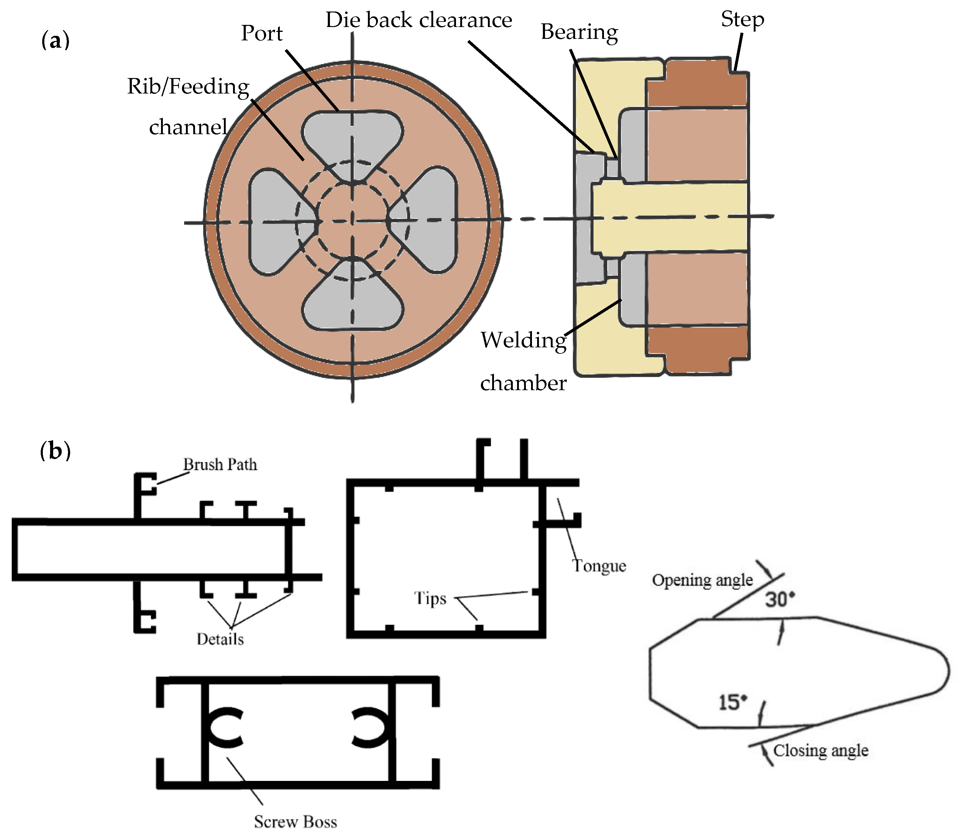
1.2. Die Structural Features
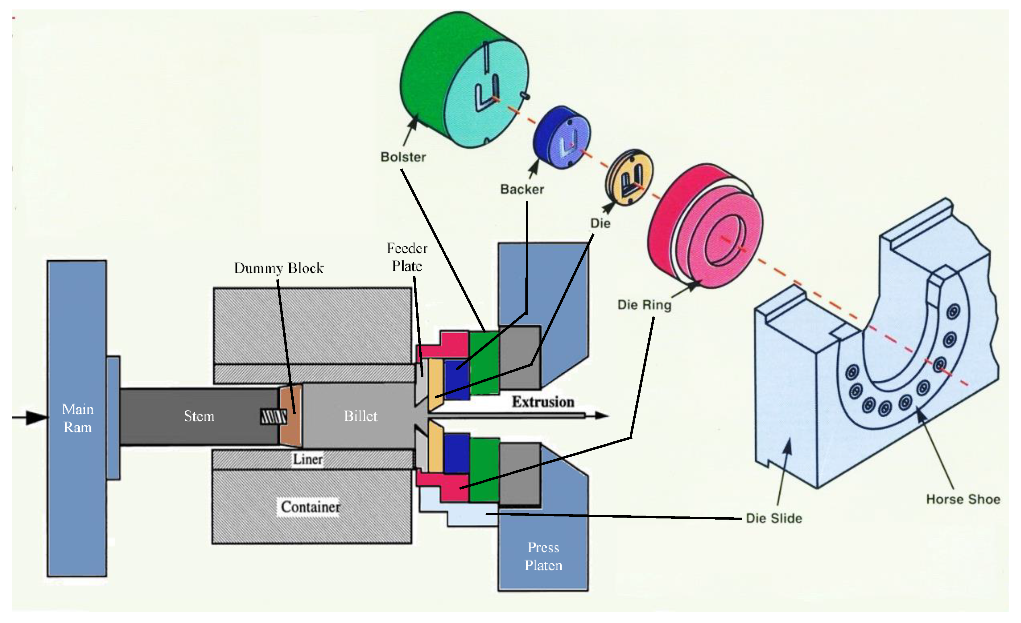
1.3. Die Tooling
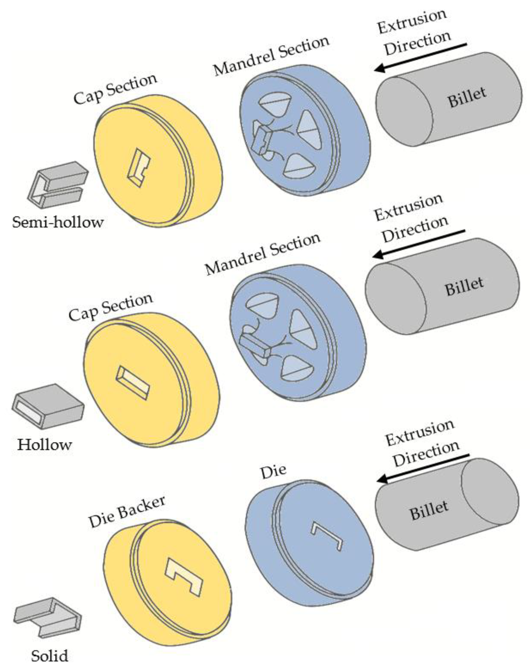
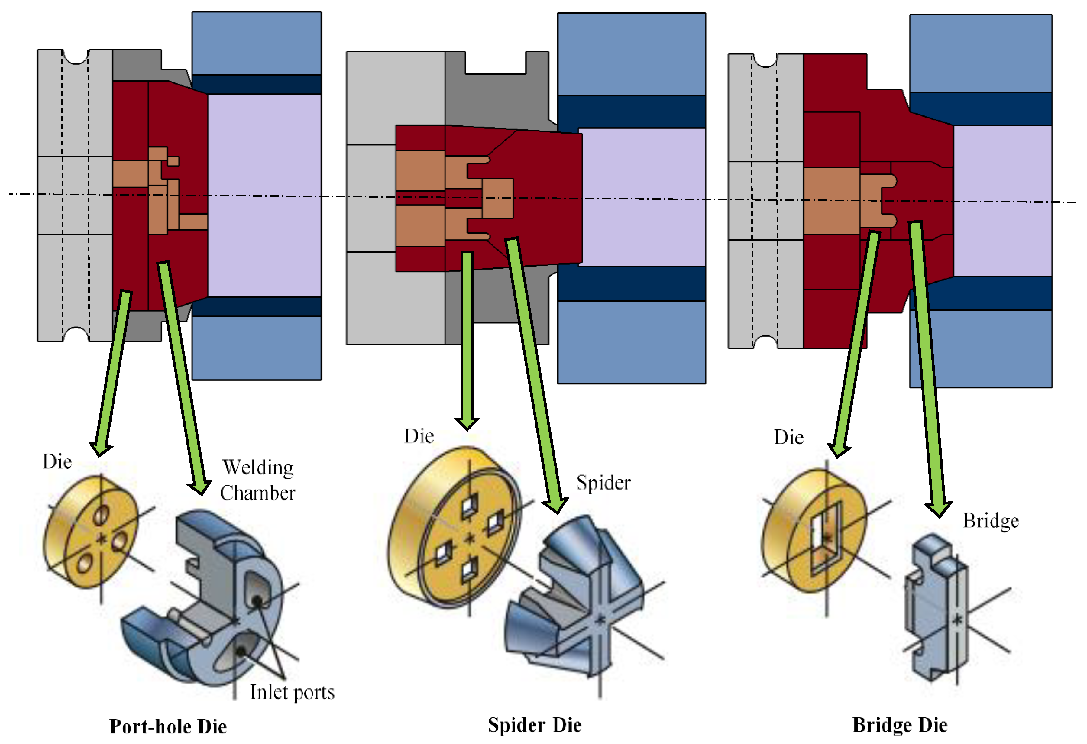
1.4. Types of Dies
2. Materials and Methods
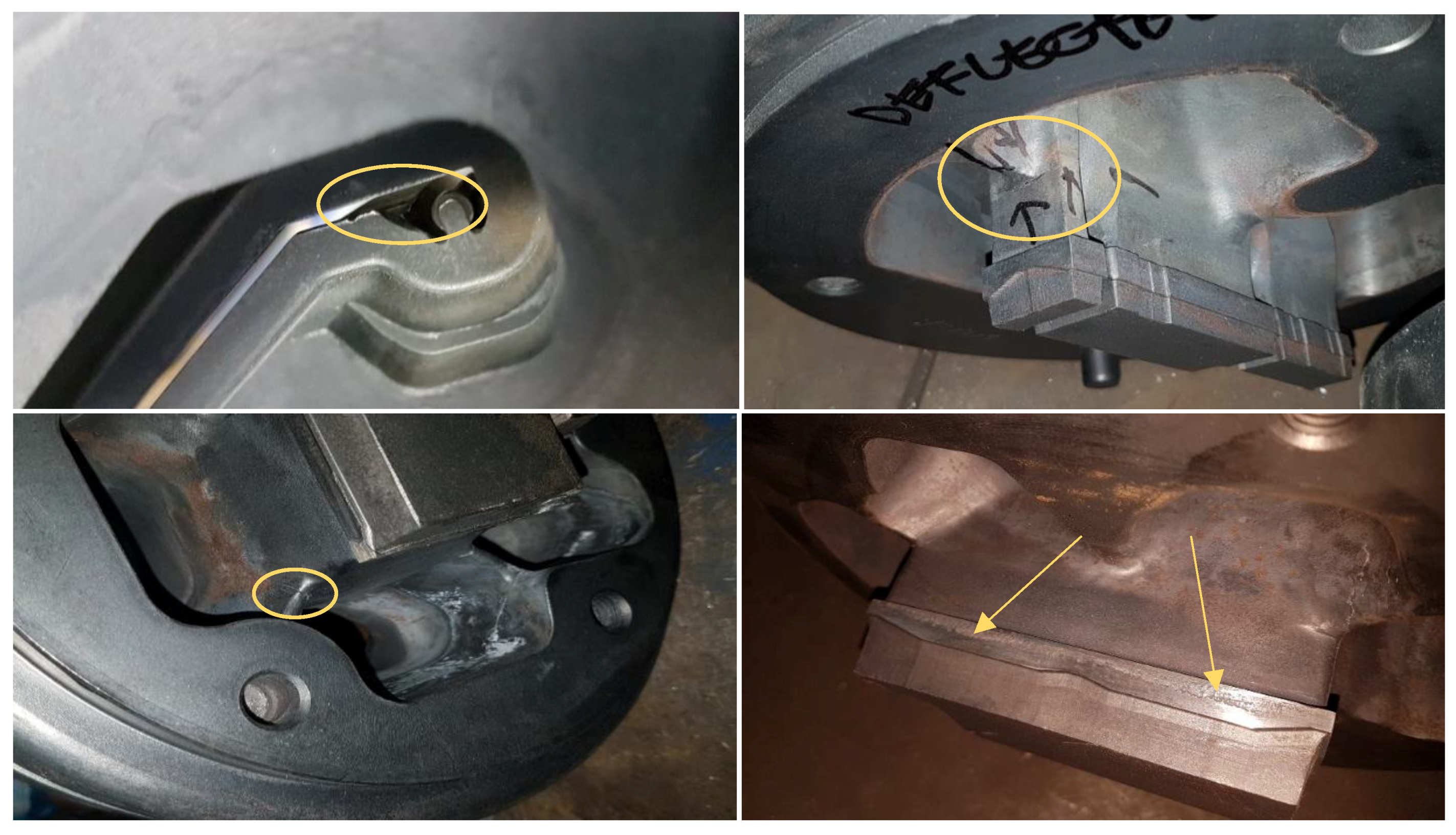
2.1. Die and Tooling Defects
2.2. Die Corrections
2.3. Die Corrector Skills
2.4. Principles of Die Correction
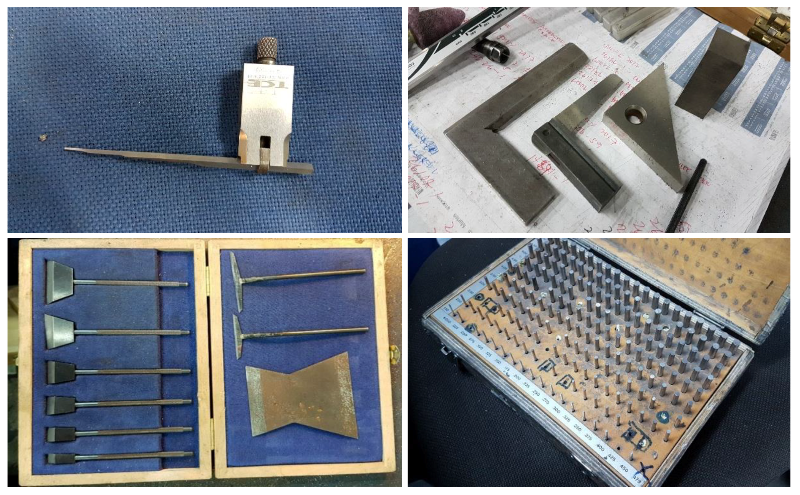
2.5. Die Inspection Tools
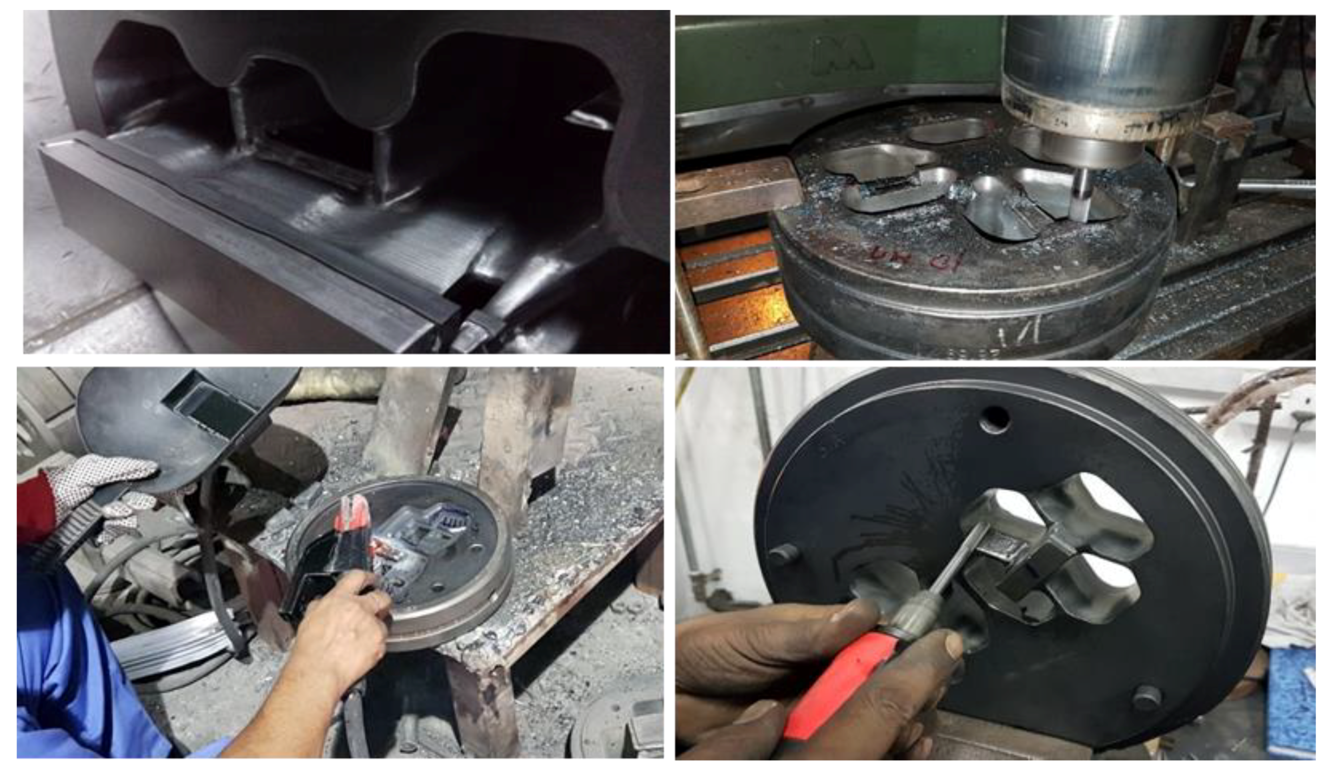
2.6. Common Die Correction Operations
2.7. Specific Die Correction Operations
3. Results and Discussion
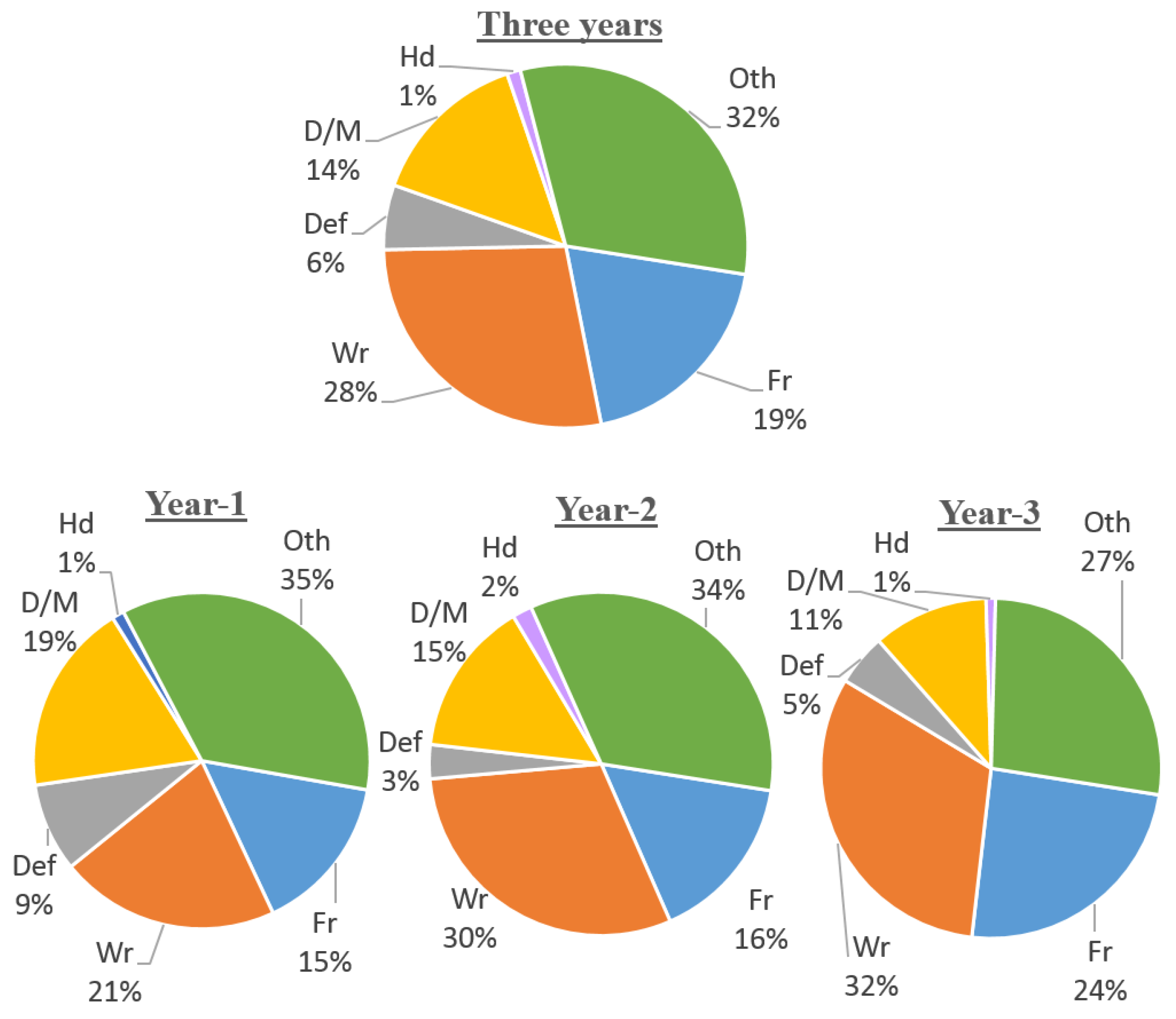
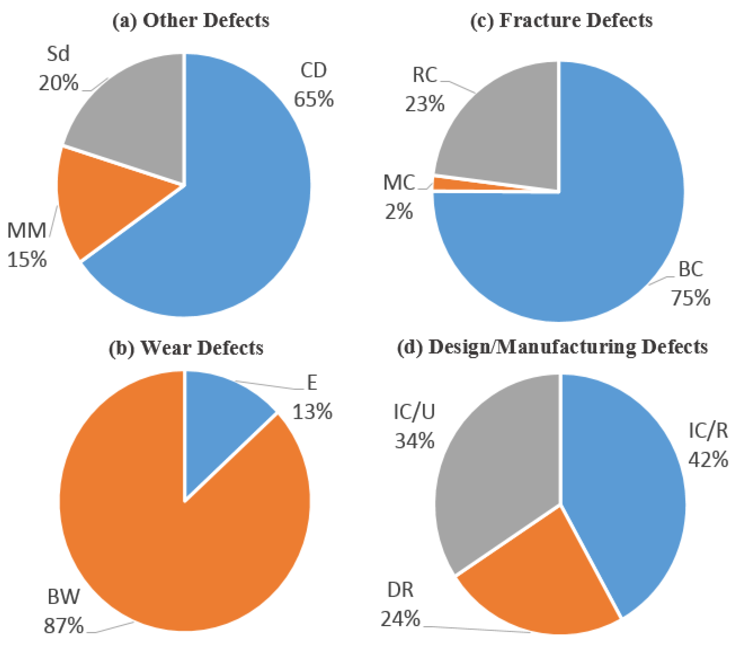
3.1. Overall Analysis
3.2. Category-Wise Breakdown
4. Conclusions
Author Contributions
Acknowledgments
Conflicts of Interest
References
- Arif, A.F.M.; Sheikh, A.K.; Qamar, S.Z.; Raza, M.K.; Al-Fuhaid, K.M. Product Defects in Aluminum Extrusion and Their Impact on Operational Cost. In Proceedings of the 6th Saudi Engineering Conference, Dhahran, Saudi Arabia, 14–17 December 2002. [Google Scholar]
- Qamar, S.Z.; Arif, A.F.M.; Sheikh, A.K. Analysis of product defects in a typical aluminum extrusion facility. Mater. Manuf. Process. 2004, 19, 391–405. [Google Scholar] [CrossRef]
- Nieto, J.T. Feature Based Costing of Extruded Parts. Ph.D. Thesis, University of Illinois, Champaign, IL, USA, 22 June 2010. [Google Scholar]
- Qamar, S.Z. Introduction to extrusion: From gear manufacturing to production of cereals. In Extrusion of Metals, Polymers, and Food Products; Qamar, S.Z., Ed.; INTECH Open Science: Pleasanton, CA, USA, 2018; ISBN 978-953-51-3838-9. [Google Scholar]
- Akhtar, S.; Arif, A.F.M. Fatigue failure of extrusion dies: Effect of process parameters and design features on die life. J. Fail. Anal. Prev. 2010, 10, 38–49. [Google Scholar] [CrossRef]
- Arif, A.F.M.; Sheikh, A.K.; Qamar, S.Z.; Al-Fuhaid, K.M. Modes of Die Failure and Tool Complexity in Hot Extrusion of Al-6063. In Proceedings of the 16th International Conference on Production Research (ICPR-16), Prague, Czech Republic, 29 July–3 August 2001. [Google Scholar]
- Arif, A.F.M.; Sheikh, A.K.; Qamar, S.Z.; Al-Fuhaid, K.M. Variation of pressure with ram speed and die profile in hot extrusion of aluminum-6063. Mater. Manuf. Process. 2001, 16, 701–716. [Google Scholar] [CrossRef]
- Li, T.; Zhao, C.; Guan, Y.; Sun, X.; Li, H. Effect of process parameters on die wear behavior of aluminum alloy rod extrusion. Mater. Manuf. Process. 2013, 28, 312–318. [Google Scholar] [CrossRef]
- Aue-u-lan, Y.; Khansai, K.; Sinpayakun, P.; Tragangoon, C. Investigation of the parameters affecting the die failure in high extrusion ratio of aluminum square hollow profile by using viscoplastic finite element modelling. Int. J. Appl. Sci. Technol. 2013, 6, 27–33. [Google Scholar]
- Qamar, S.Z. Modeling and Analysis of Extrusion Pressure and Die Life for Complex Aluminum Profiles. Ph.D. Thesis, King Fahd University of Petroleum & Minerals, Dhahran, Saudi Arabia, June 2004. [Google Scholar]
- Yilbas, B.; Arif, A.F.M.; Akhtar, S. Finite element simulation of the effect of Al-6063 billet quality on the extrusion die performance. Ind. Lubr. Tribol. 2013, 65, 78–90. [Google Scholar] [CrossRef]
- Qamar, S.Z.; Sheikh, A.K.; Arif, A.F.M. Modeling and Analysis of Aluminum Extrusion: Process, Tooling, and Defects; LAP Lambert Academic Publishing: Saarbrücken, Germany, 2011; ISBN 9783844331585. [Google Scholar]
- Lepadatu, D.; Hambli, R.; Kobi, A.; Barreau, A. Statistical investigation of die wear in metal extrusion processes. Int. J. Adv. Manuf. Technol. 2006, 28, 272–278. [Google Scholar] [CrossRef]
- Kazanowski, P. Die Performance Optimization through Understanding of the Surface Features of Fatigue Fractures; Hydro Aluminum Cedar Tools: Cedar Springs, MI, USA, 2008. [Google Scholar]
- Qamar, S.Z. Fracture life prediction and sensitivity analysis for hollow extrusion dies. Fatigue Fract. Eng. Mater. Struct. 2015, 38, 434–444. [Google Scholar] [CrossRef]
- Zhang, C.; Zhao, G.; Li, T.; Guan, Y.; Chen, H.; Li, P. An investigation of die wear behavior during aluminum alloy 7075 tube extrusion. J. Tribol. 2013, 135. [Google Scholar] [CrossRef]
- Arif, A.F.M.; Sheikh, A.K.; Qamar, S.Z. A study of die failure mechanisms in aluminum extrusion. J. Mater. Process. Technol. 2003, 134, 318–328. [Google Scholar] [CrossRef]
- Sheppard, T. Extrusion of Aluminum Alloys; Kluwer Academic: Dordrecht, Germany, 2013. [Google Scholar]
- Laue, K.; Stenger, H. Extrusion: Processes, Machinery, Tooling; American Society for Metals: Metals Park, OH, USA, 1981. [Google Scholar]
- Qamar, S.Z.; Arif, A.F.M.; Sheikh, A.K.; Pervez, T. Effect of process parameters on metal flow and dead metal zone in extrusion. Arch. Mater. Sci. 2008, 28, 118–123. [Google Scholar]
- Bauser, M.; Siegert, K. Strangpressen, 2nd ed.; Aluminium Verlag: Munich, Germany, 2001. [Google Scholar]
- Mielnik, E.M. Metalworking Science and Engineering; McGraw-Hill: New York, NY, USA, 1991. [Google Scholar]
- Lange, K. Handbook of Metal Forming; McGraw-Hill: New York, NY, USA, 1985. [Google Scholar]
- Saha, P.K. Aluminum Extrusion Technology; ASM International: Materials Park, OH, USA, 2000; ISBN 9781615032457. [Google Scholar]
- Qamar, S.Z.; Sheikh, A.K.; Arif, A.F.M.; Pervez, T. Defining shape complexity of extrusion dies—A reliabilistic view. Mater. Manuf. Process. 2007, 22, 804–810. [Google Scholar] [CrossRef]
- Chang, K.H.; Shih, C.W.; Tzou, G.Y. Defect improvement of extrusion dies using combination of fem stress analysis with the taguchi method. Trans. Can. Soc. Mech. Eng. 2015, 39, 729–738. [Google Scholar] [CrossRef]
- Zhang, C.; Zhao, G.; Guan, Y.; Gao, A.; Wang, L.; Li, P. Virtual tryout and optimization of the extrusion die for an aluminum profile with complex cross-sections. Int. J. Adv. Manuf. Technol. 2015, 78, 927–937. [Google Scholar] [CrossRef]
- Qamar, S.Z.; Pervez, T.; Al-Moharbi, A.D. Fracture Prediction of Extrusion Die Modeled as Pressurized Cylinder with Internal Crack. In Proceedings of the 15th International Research/Expert Conference on Trends in the Development of Machinery and Associated Technology (TMT 2011), Prague, Czech Republic, 12–18 September 2011. [Google Scholar]
- Qamar, S.Z.; Arif, A.F.M.; Sheikh, A.K.; Younas, M.; Pervez, T.; Siddiqui, R.A. Simulation of Fatigue and Wear Life of Extrusion Dies. In Proceedings of the 10th International Research/Expert Conference on Trends in the Development of Machinery and Associated Technology (TMT 2006), Barcelona, Lloret de Mar, Spain, 11–15 September 2006. [Google Scholar]
- Qamar, S.Z.; Arif, A.F.M.; Sheikh, A.K.; Al Fuhaid, K.M. Some Observations on Pressure Distribution and Die Failure Modes in Hot Extrusion. In Proceedings of the 6th Saudi Engineering Conference, Dhahran, Saudi Arabia, 14–17 December 2002. [Google Scholar]
- Qamar, S.Z.; Siddiqui, R.A.; Pervez, T.; Sheikh, A.K.; Arif, A.F.M. Improvement of Die Design and Prevention of Die Failure in Metal Extrusion. In Proceedings of the 12th International Research/Expert Conference on Trends in the Development of Machinery and Associated Technology, Istanbul, Turkey, 26–30 August 2008; pp. 869–872. [Google Scholar]
- Schey, J.A. Introduction to Manufacturing Processes, 3rd ed.; McGraw-Hill: New York, NY, USA, 2000; ISBN 978-0070311367. [Google Scholar]
- Kalpakjian, S. Manufacturing Processes for Engineering Materials, 6th ed.; Addison-Wesley: Menlo Park, CA, USA, 2017. [Google Scholar]
- Groover, M.P. Fundamentals of Modern Manufacturing: Materials, Processes and Systems, 5th ed.; John Wiley & Sons: Hoboken, NJ, USA, 2012. [Google Scholar]
- Qamar, S.Z.; Pervez, T.; Chekotu, J.C. Correctable Die Defects in Aluminum Extrusion. In Proceedings of the World Congress on Mechanical and Mechatronics Engineering, Dubai, UAE, 16–17 April 2018. [Google Scholar]
- Fielding, R.A.P.; Johannes, V.I. The evolution and changing role of die correction in the production of extrusions. Light Met. Age 2005, 63, 6–21. [Google Scholar]
- Qamar, S.Z.; Sheikh, A.K.; Arif, A.F.M.; Younas, M.; Pervez, T. Monte carlo simulation of extrusion die life. J. Mater. Process. Technol. 2008, 202, 96–106. [Google Scholar] [CrossRef]
- Qamar, S.Z. Optimum heat treatment of extrusion die steel. Adv. Mater. Res. 2014, 911, 215–219. [Google Scholar] [CrossRef]
- Qamar, S.Z. Product Defects in Commercial Aluminum Extrusion: Review and Analysis. In Proceedings of the International Conference on Advances in Materials and Processing Technologies (AMPT 2016), Kuala Lumpur, Malaysia, 8–11 November 2016. [Google Scholar]
- Qamar, S.Z.; Chekotu, J.C.; Pervez, T. Mitigation of Major Product Defects in Aluminum Extrusion. In Proceedings of the 14th International Conference and Exhibition on Materials Science and Engineering, Las Vegas, NV, USA, 13–15 November 2017. [Google Scholar]
- Qamar, S.Z. Shape complexity, metal flow, and dead metal zone in cold extrusion. Mater. Manuf. Process. 2010, 25, 1454–1461. [Google Scholar] [CrossRef]


| Die/Tooling Defects | Sub-Categories |
|---|---|
| Fracture | Bearing crack; Mandrel crack; Rib crack; Fracture/breakage |
| Wear | Erosion; Bearing washout |
| Deflection | Feature deflection; Mandrel/cavity deflection |
| Design/manufacturing | Improper choke/relief; Distended rib; Improper clearance/undercut |
| Hardness | Soft die bearing; Peeling; Chipping |
| Other | Correction defects; Mixed mode; Setup damages |
| Skill Areas | Description/Details |
|---|---|
| Die technology | Types of dies; supporting components; die material behavior; die manufacturing and nitriding processes; die geometry parameters and their effect; die defects; extrusion process parameters |
| Die support technology | Compatibility of bolsters and backers; typical faults due to poor compatibility; softening of components; tolerance matching between feeder plates and die bearing |
| Common faults and their causes | Variations in run-out lengths; misalignment of die slides; flow speed difference; container geometry; bearing performance; surface defects; nitrided layer flaking off; blockages; breakdowns |
| Analysis | Die performance monitoring; recording and comparing performance and correction data; balancing speed, tonnage, and recovery rates against die corrections; identifying the need for a new die or major repairs by the manufacturer; detecting and suggesting alterations in design; documentation of changes in drawings |
| Die Correction Operations | Related Die/Tooling and Product Defects |
|---|---|
| Shortening of bearings; Choking | Die defects—design/manufacturing defects, correction defects Product defects—concavity/convexity, twists, off angle, speed difference, ripping |
| Heating and realigning | Die defects—fracture defects, deflection defects Product defects—off dimension, twists and bends |
| Chiseling | Die defects—erosion, rib design defects, correction defects Product defects—die lines, rough surface, flashing, weld defects |
| Peening | Die defects—deflection defects, fracture defects, wear defects Product defects—die lines, off angle, off dimensions |
| Undercutting; Increasing depth; Increasing clearance | Die defects—design/manufacturing defects, correction defects Product defects—weld defects, concavity/convexity, cracks, speed difference, flashing, ripping |
| Welding | Die defects—erosion/damage, fracture defects, chipping, feature deflections Product defects—pick-up defect, die lines, roughness, streaks, surface cracks, etc. |
| Grinding; Machining and skimming | Die defects—wear defects, fracture defects, design and correction defects Product defects—die lines, streaks, pick-up defect, rough surface |
| Cleaning and polishing; Nitriding; Carbo-nitriding | Die defects—wear defects, hardness defects Product defects—pick-up defect, die lines, streaks, blisters/blowholes |
| Die Defects | Related Correction Operations | |
|---|---|---|
| Fracture defects |
|
|
| Wear defects |
|
|
|
| |
|
| |
| Deflection defects |
| |
| ||
| Design/Manufacturing defects |
|
|
|
| |
|
| |
|
| |
| Hardness defects |
| |
| ||
| Correction defects |
|
|
|
| |
|
| |
© 2018 by the authors. Licensee MDPI, Basel, Switzerland. This article is an open access article distributed under the terms and conditions of the Creative Commons Attribution (CC BY) license (http://creativecommons.org/licenses/by/4.0/).
Share and Cite
Qamar, S.Z.; Pervez, T.; Chekotu, J.C. Die Defects and Die Corrections in Metal Extrusion. Metals 2018, 8, 380. https://doi.org/10.3390/met8060380
Qamar SZ, Pervez T, Chekotu JC. Die Defects and Die Corrections in Metal Extrusion. Metals. 2018; 8(6):380. https://doi.org/10.3390/met8060380
Chicago/Turabian StyleQamar, Sayyad Zahid, Tasneem Pervez, and Josiah Cherian Chekotu. 2018. "Die Defects and Die Corrections in Metal Extrusion" Metals 8, no. 6: 380. https://doi.org/10.3390/met8060380
APA StyleQamar, S. Z., Pervez, T., & Chekotu, J. C. (2018). Die Defects and Die Corrections in Metal Extrusion. Metals, 8(6), 380. https://doi.org/10.3390/met8060380