Abstract
In the present study, the influence of hydrogen on the fatigue behavior of the high strength martensitic stainless steel X3CrNiMo13-4 and the metastable austenitic stainless steels X2Crni19-11 with various nickel contents was examined in the low and high cycle fatigue regime. The focus of the investigations were the changes in the mechanisms of short crack propagation. Experiments in laboratory air with uncharged and precharged specimen and uncharged specimen in pressurized hydrogen were carried out. The aim of the ongoing investigation was to determine and quantitatively describe the predominant processes of hydrogen embrittlement and their influence on the short fatigue crack morphology and crack growth rate. In addition, simulations were carried out on the short fatigue crack growth, in order to develop a detailed insight into the hydrogen embrittlement mechanisms relevant for cyclic loading conditions. It was found that a lower nickel content and a higher martensite content of the samples led to a higher susceptibility to hydrogen embrittlement. In addition, crack propagation and crack path could be simulated well with the simulation model.
1. Introduction
The demand for more efficient and cleaner technologies provides the impulse to establish hydrogen as an energy carrier, for example in the automotive sector. This field of applications has already been the center of research for a long time, where an important focus is put on a reliable and safe fatigue life prediction for weight-optimized and cyclically loaded components.
Mechanically stressed automotive components such as pressure vessels, pipes, valves, and compressors are exposed to hydrogen and stress amplitudes that are suitable for LCF-/HCF fatigue. The combination of mechanical stress and hydrogen environment can lead to more rapid material failure resulting from hydrogen embrittlement effects. For this application, a good knowledge about the short crack propagation during the LCF-/HCF regime is necessary.
Also from the known literature [1,2] it can be seen that short-crack growth accounts for a significant proportion of the total lifetime, both on uncharged specimens and on specimens under compressed hydrogen atmosphere. It is also known for austenitic stainless steels that hydrogen can lead to a reduction of the total lifetime [3].
However, most of the research on hydrogen embrittlement of stainless steels deals with the characterization of long fatigue crack growth behavior [3,4] or the effect of hydrogen on monotonic properties obtained in tensile tests [5,6]. There is only little information available about the mechanisms of crack initiation and early crack growth.
Hence, the aim of this study is the identification of the changing microstructural mechanisms of fatigue crack initiation and crack propagation of microstructurally small fatigue cracks resulting from the presence of hydrogen in one martensitic and in two metastable austenitic stainless steels.
To investigate the influence of hydrogen on the total lifetime, the aim of this research project is to perform a detailed characterization of the mechanisms of material damage of different steel types under the influence of hydrogen with respect to short crack growth in the LCF/HCF regime. In order to separate the influence of internal and external hydrogen, tests are carried out at the Materialprüfungsanstalt in Stuttgart (MPA) under pressurized hydrogen and tests with precharged specimens at the Institut für Werkstofftechnik. Also, corresponding reference tests are carried out with uncharged specimens in vacuum and pressurized helium. Two metastable austenitic stainless steels and one martensitic stainless steel X3CrNiMo13-4 are investigated. Both austenitic stainless steels were produced based on an X2CrNi19-X (1.4306) and differ essentially chemically in their nickel content (9.07% and 12.36%, respectively).
An important second focus of this project is the transfer of the results from the experimental investigations into the physically based modeling and the conversion into a simulation program. The developed two-dimensional model, which uses the boundary element method for the numerical determination of mechanical quantities, already enables the validated simulation of short crack propagation and phase transformation under the influence of microstructural barriers such as grain and phase boundaries [7,8].
The combination of experimental and simulation work should lead to a fundamental understanding of the metal-physical processes in hydrogen-exposed materials under cyclic stress.
2. Hydrogen Embrittlement Mechanisms
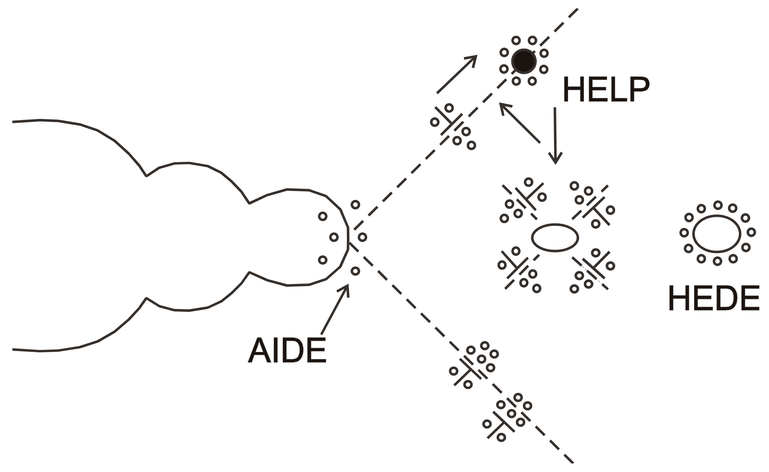
In literature, many mechanisms are presented to describe different phenomena of hydrogen effects during crack propagation, but there are some mechanisms that are generally accepted. These main mechanisms of hydrogen embrittlement can occur alone and combined, so that different embrittlement mechanisms take in the various stages of material damage the dominant role. The three main mechanisms are briefly explained below and shown schematically in Figure 1.
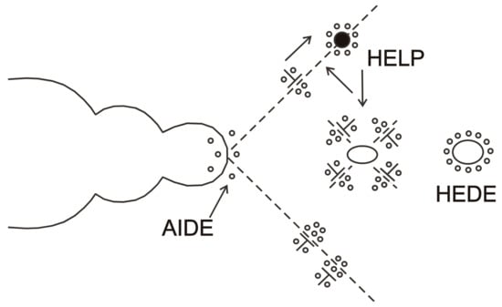
Figure 1.
Schematic illustration of three hydrogen embrittlement mechanisms: Hydrogen-Enhanced Localized Plasticity (HELP), Hydrogen-Enhanced Decohesion (HEDE) and Adsorption-Induced Dislocation Emission (AIDE) [12].
2.1. Hydrogen-Enhanced Localized Plasticity (HELP)
The HELP theory tries to explain premature damage by hydrogen by an increased dislocation mobility. It assumes that stored hydrogen accumulates like a Cottrell atmosphere in the stress fields of dislocations. This accumulation of hydrogen reduces the stress field of the dislocation and thus locally reduces the mutual stress of dislocations. As a result, a lower external stress is necessary to trigger a dislocation movement than without hydrogen [9].
2.2. Hydrogen-Enhanced Decohesion (HEDE)
The HEDE theory describes the hydrogen induced embrittlement in metals as a result of reduced binding forces between the matrix atoms due to localized accumulations of stored hydrogen. These local accumulations are found in elastically expanded areas as in grain boundaries or phase boundaries. Especially in areas of high tension as in front of cracks, the hydrogen can get in the elastically distorted lattice and thus reduce the necessary crack energy. This explains when hydrogen-induced cracks grow preferentially at grain boundaries, phase boundaries or in areas of high dislocation density [10].
2.3. Adsorption-Induced Dislocation Emission (AIDE)
Petch [11] developed the adsorption theory by explaining the hydrogen embrittlement by the decrease of the surface energy due to the adsorption of hydrogen. The stored hydrogen accumulates in lattice areas around microcracks. There, the energy required for cracking is reduced by the amount between the surface energy with and without adsorbed hydrogen.
3. Materials and Methods
3.1. Materials
In order to investigate the influence of nickel content on the fatigue behavior of the metastable austenitic stainless steel X2CrNi19-X with simultaneous exposure to hydrogen, two variants of the material X2CrNi19-X were smelted and forged with nickel contents of 9.07% and 12.36% (referred to below as X2–9 and X2–12, respectively). This allows to separate the influence of a martensitic transformation and the effects of hydrogen on the short crack propagation.
Specimens for the reference tests in Siegen were precharged with hydrogen from the gas phase (approx. 180 °C, 180 bar H2, 28 days) in the autoclave at the MPA. The reached hydrogen contents were measured in Siegen using a hydrogen analyzer LECO by means of hot gas extraction. Furthermore, specimens without hydrogen were tested as reference under identical conditions.
In order to contrast the behavior of a martensitic stainless steel with the two metastable austenitic stainless steels, the X3CrNiMo13-4 (designated as X3) was tested. The chemical composition of the materials is shown in Table 1.

Table 1.
Chemical composition (in (wt. %)) of the tested alloys.
Metastable austenitic stainless steels (X2–9 and X2–12) show a deformation-induced martensite formation during fatigue. This phase transformation of γ-austenite (fcc) into α′-martensite (bcc) occurs spontaneously, without any diffusion and a lattice-distorting effect, in which the respective atoms remaining neighbors in the metal lattice. For the phase transformation, the martensite starting temperature MS [K] (Equation (1)) must be lowered.
A threshold value for the transformation, which is determined by the difference of the free energies of both phases ΔG, is reached. A temperature-induced transformation can only proceed below MS, above MS a mechanical deformation energy ΔGmech must be additionally applied. Above a high temperature T0, no phase transformation is possible. The martensite starting temperature, MS, can be estimated using the following empirical equation [13]:
In addition to the martensite starting temperature, the Schaeffer diagram can also be used to characterize the tendency to a martensitic phase transformation. It represents the phases that are present at room temperature in CrNi steels, for which nickel and chromium equivalents are calculated and plotted in the diagram. According to Equations (2) and (3), the effect of the main alloying elements on the phase transformation can be taken into account.
The nickel equivalent is 10.35 for the X2–9 and 13.715 for the X2–12. The martensite starting temperature MS is calculated to −276.86 °C for the X2–12 and −82.59 °C for the X2–9. Both the calculated values and the Schaeffer diagram show that the X2–9 has a stronger tendency for a martensitic transformation than the X2–12 [13].
3.2. Testing Machines
The fatigue tests were carried out in Siegen with a servohydraulic test system, equipped with a vacuum chamber and with a miniature electromechanical testing machine, which is chamber-expanded into a Philips XL30 LaB6 scanning electron microscope (SEM). The miniature testing machine is operating by a piezoelectric actuator and can be used for cyclic tests up to 30 Hz and maximum stresses of 390 MPa. In order to carry out fatigue tests in addition to vacuum reference samples in-situ in laboratory air with high-resolution observation, the miniature testing machine was adapted outside its chamber extension to a confocal laser microscope.
The initiation and growth of microstructural short fatigue cracks was observed at the servo-hydraulic testing system by far-field microscopy. The experiments on the miniature testing machine (Figure 2) were carried out quasi in situ using a confocal laser microscope. For this purpose, images of the sample surface were taken at fixed intervals (5000 cycles) and later evaluated for the reconstruction of the crack initiation and the crack length. The investigation of fracture surfaces and microstructures was carried out on a SEM from the company FEI (Helios), surface measurements were made by using a confocal laser microscope manufactured by Olympus. At the MPA in Stuttgart a servohydraulic testing machine with installed autoclave was used. Both the hydrogen and helium experiments were carried out at 10 MPa. Figure 3 shows the sample geometries used in Siegen and Stuttgart.
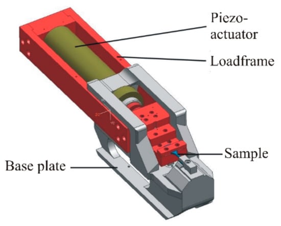
Figure 2.
Functional representation of the miniature testing machine [14].
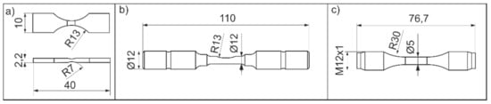
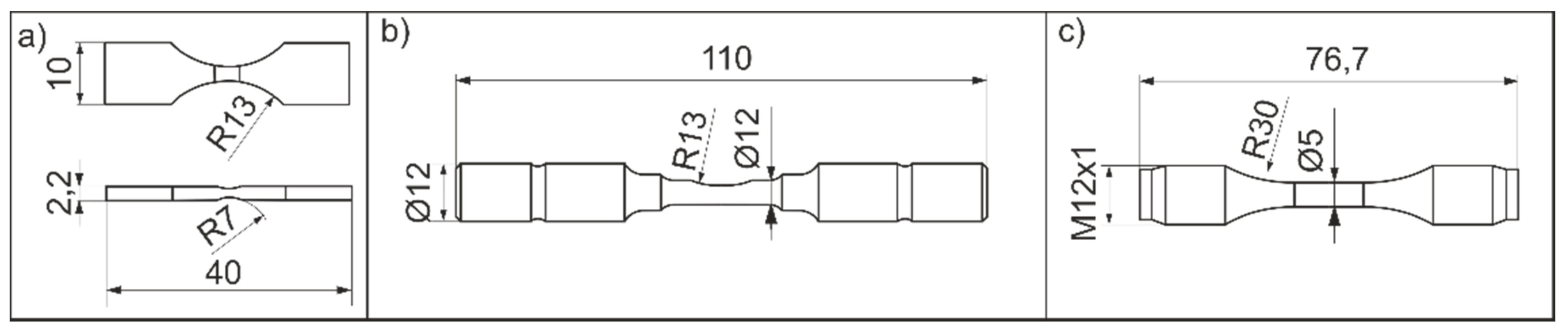
Figure 3.
Specimen geometry (a) in situ specimen with two shallow notches, Siegen; (b) servohydraulic specimen with single shallow notch, Siegen; (c) servohydraulic specimen, Stuttgart.
To observe the short-crack propagation even under pressurized hydrogen quasi in situ, the replica method was used at the MPA. The autoclave is opened at defined intervals to make replicas of the surface.
3.3. Modelling the Influence of Hydrogen on Short Fatigue Crack Propagation
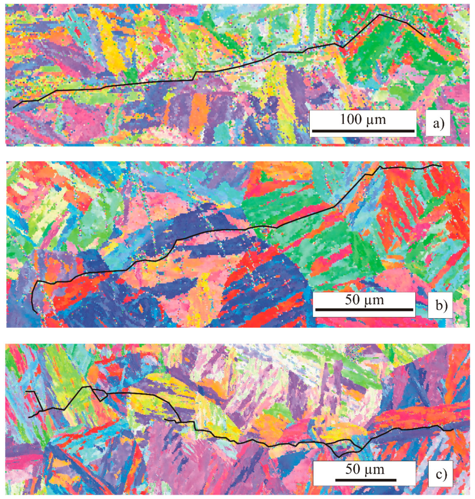
To simulate short fatigue cracks, a two-dimensional boundary element method (BEM) is used. In this model, the influence of the microstructure on the short crack propagation is directly taken into account, such as: the barrier effect of grain boundaries, the evolution of slip bands or local martensitic phase transformation in metastable austenitic stainless steels. For this purpose, the grain boundaries of the microstructure as well as the slip bands within the individual grains are explicitly modelled. The short crack growth is predicted on the basis of a predefined initial crack whose position can be taken from the SEM image (see Figure 4).
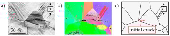
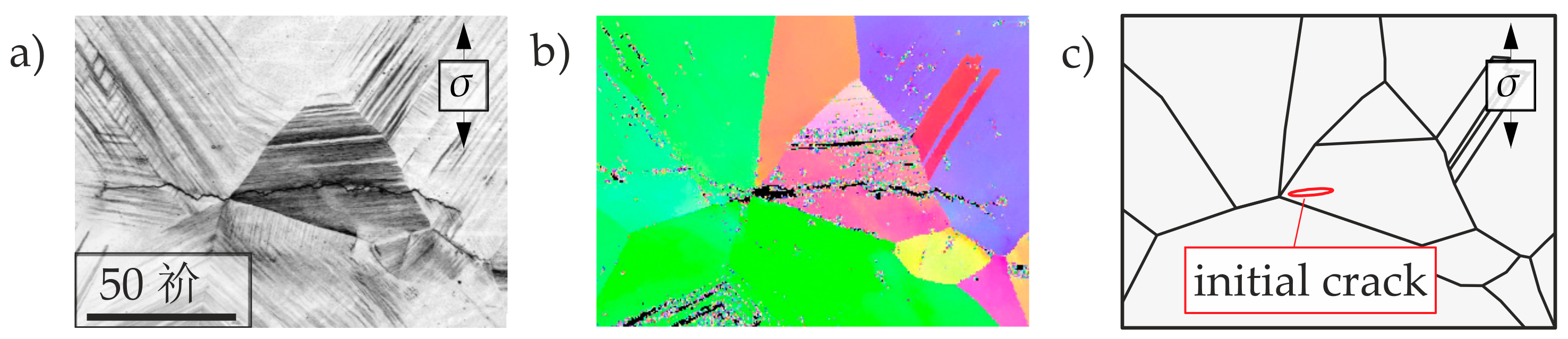
Figure 4.
Scanning electron micrograph (a) and electron backscattered diffraction technique (EBSD) image of the polycrystalline microstructure of X2–12 (b) and discretization of the grain boundaries and the initial crack in the short crack growth model (c).
In the boundary element method, absolute displacements are calculated at the grain boundaries and relative displacements are determined for slip band and crack elements. In contrast to the discretization with the finite element method, only the edges of the area (grain and phase boundaries) as well as the cracks and the slip bands are meshed. For the approximation of the stresses as well as the displacements quadratic shape functions are used and analytically integrated by using fundamental solutions for an anisotropic elastic solid. In order to simulate a heterogeneous, polycrystalline microstructure with different elastic anisotropic properties, sub-regions at the common edge of the region can be connected to each other in the boundary element method by the substructure technique [8]. This is achieved by defining the following boundary conditions. At the common edges, the displacements must be equal and the boundary stresses have the same value, but opposite signs. This modelling approach is important, because each individual grain can be assigned to individual anisotropic elastic properties. The anisotropic elastic properties are determined from the corresponding three-dimensional rotation of the anisotropic elasticity tensor of the unit cell according to the measured crystallographic orientations from the EBSD image in the scanning electron microscope (see Figure 4b).
The crystallographic orientation of the crystal structure (face-centered cubic fcc or body-centered cubic bcc) determines the slip systems within a grain. The model considers the {111} <110> slip systems in the fcc lattice and the {110} <111> slip systems in the bcc lattice. According to [8], the sliding along these shear bands as well as the stresses were projected to the x-y plane. However, sliding occurs in the three-dimensional direction of the slip system. Therefore, the model has been extended to transform the sliding and the shear stresses onto the actual slip directions determined from the EBSD measurements [15]. This is done by assuming that the general plane stress state with the condition σ33 = 0 is valid at the sample surface. Thus, displacements in normal direction to the surface plane and stresses in the direction of the slip systems can be calculated with a two-dimensional discretization.
At the beginning of the simulation, it is assumed that there are no activated shear bands at the crack tip. Therefore, the shear stresses in each slip system at the crack tip are calculated first. If a critical shear stress for activating a slip band at the crack tip is exceeded (), the shear stress along the newly discretized slip band is evaluated and limited to the friction stress . This creates an additional sliding along the slip band in the direction of the activated slip system in a three-dimensional direction, which also changes the crack displacements. Further, it is determined if at the end of each newly discretized slip band, the condition for an additional slip band formation is fulfilled. With the described model, the stresses in the individual grains as well as the displacements of the crack can be calculated taking into account the deformation processes of the slip bands.
In addition to this slip band model, a distinction is made between the inter- and transgranular crack growth, as shown schematically in Figure 5. The intergranular crack growth is usually dominated by the slip bands forming at the crack tip, whereas the transgranular crack growth is controlled by the particular grain boundaries. In the crack growth model, these mechanisms are described by two distinctive approaches for determining the crack growth rate; see Equations (4) and (5).

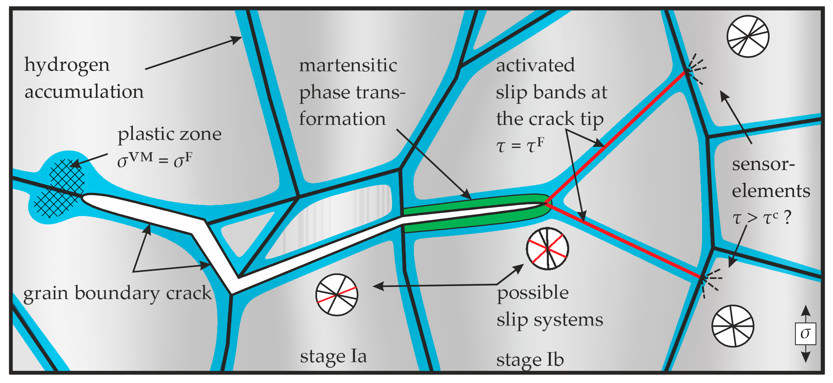
Figure 5.
Schematic of the short crack growth model.
According to Wilkinson [16], the microstructurally short crack growth along shear bands is significantly influenced by the range of the crack tip slide displacement ΔCTSD:
whereas crack growth at grain boundaries are controlled by normal stress at the boundary resulting in a crack tip opening CTOD [KÖS2015]. Thus, the crack growth rate is evaluated by:
The irreversibility factors C and the exponents m (with the associated indices) are material-specific values and are adjusted once based on experimentally obtained results. In order to solve these equations, an incremental crack propagation (da → Δa) is defined in the model in order to determine the required load cycles ΔN for crack growth.
According to Equation (4), the crack growth results from the range of the crack tip slide displacement ΔCTSD in the vicinity of the crack tip. If only one slip band is active at the crack tip, the crack growth takes place in the direction of the active slip band (crack growth stage Ia). If two shear bands are active at the crack tip, the crack growth is characterized by the alternate sliding of the shear bands (crack growth stage Ib). In consequence, the crack propagation occurs in the direction determined by vectorially adding the slip along the shear bands active at the crack tip [7].
If two shear bands are active at the crack tip, the model also investigates whether a martensitic phase is formed in the investigated metastable austenitic stainless steels. As a basis for the simulation of deformation-induced martensite formation at the crack tip, the short crack propagation model by [8] is used. Here, the newly formed martensitic phase is discretized as a new area and the corresponding volume expansion associated with the phase transformation is applied. This model was extended by [15] and considers the deformation-induced martensite formation according to the model of Olsen and Cohen [17], where two compatible shear deformations along specific slip systems have to occur at the crack tip.
If the crack tip reaches a grain boundary, it is evaluated whether the crack grows either by the activation of shear bands or along the grain boundary. The activation of a grain boundary takes place if a critical normal stress is exceeded. The condition for plastic deformations along the grain boundary is modelled by comparing the present von-Mises stress with the cyclic yield stress . In the case where the critical stress is exceeded in the slip systems as well as at the grain boundary, further crack growth occurs by comparing along the grain boundary and in the slip systems. The critical value from this comparison determines the crack growth behavior [18].
The experimental studies of the damage behavior of the investigated materials under the influence of hydrogen indicate that hydrogen influences the local slip deformation in slip bands as well as the barrier effect of grain boundaries (see chapter 4.1; [19]). This is also confirmed by molecular dynamic simulations (in e.g., [20]). Due to these reasons, a phenomenological approach is used to model the influence of hydrogen in the mesoscale description of the short fatigue crack growth. The friction stress and the activation of slip bands and the barrier effect of grain boundaries is expressed as a function of the local hydrogen concentration (cf. [21]):
Here, and are material-dependent parameters that have to be adjusted to experimentally obtained data on the short crack propagation. The same approach as in Equations (6) or (7) is used to describe the effect of hydrogen on the irreversibility factors und as a function of the locally present hydrogen concentration. The extent to which these approaches have to be used has to be concluded from the simulation results and the comparison with experimental results of the short crack propagation. But to adequately use the approaches given in Equations (6) and (7), the local distribution of the hydrogen concentration in the microstructure is required, which can be determined by a diffusion model further explained below.
3.3.1. Description of the Diffusion Model
In the short crack growth model, it is assumed that the hydrogen-related material parameters (, and C) do not change during one simulation cycle with constant crack length. Only after the crack advances by the predefined crack growth increment Δa, the redistribution of the local hydrogen concentration is determined. Due to this, a transient stress-driven diffusion model is presented, which takes into account the transient effects on the hydrogen distribution in the microstructure. For this purpose the time Δtc for the diffusion process has to be calculated. This is accomplished by dividing the previously determined incremental loading cycle ΔN calculated in the short crack growth model by the frequency f given from the experimental setup:
If the time for the incremental crack growth is known, the redistribution of the initially homogeneous hydrogen concentration can be determined. Ensuing, the hydrogen-related material parameters described above are adjusted for the next crack growth cycle. The model for calculating the hydrogen concentration in the microstructure is based on the consideration of hydrostatic stresses on the chemical potential [22]. The following diffusion equation can be established using Fick’s laws:
This differential equation describes the transient hydrogen distribution which further depends on the transient hydrostatic stresses in the microstructure and the hydrogen diffusion coefficient D, the partial molar volume of hydrogen , the gas constant R, the temperature T, and the time t. According to Equation (9), hydrogen accumulates at sites with high hydrostatic tensile stresses, in particular at the crack tip. The transient hydrostatic stresses are defined in Equation (10) according to Einstein’s summation convention (i = 1, 2, 3) and can be calculated directly from the short crack propagation model:
The calculation of the stress gradients in Equation (9) numerically occurs by a linear approximation of the calculated hydrostatic stress field. The transient evolution of the stresses is approximated in the diffusion model by a constant stress field over a time increment Δt according to Figure 6. Δt results from the sinusoidal signal of the external load and the calculated load steps in the short crack growth model.
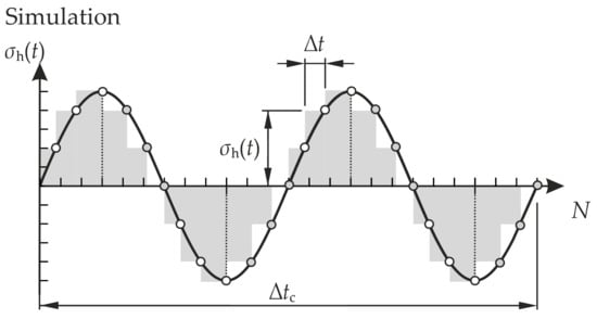
Figure 6.
Approximation of the hydrostatic stresses in the diffusion model.
In the diffusion model, it is assumed that at the beginning of the crack growth simulation for precharged specimens an initial homogeneous hydrogen distribution is present or in the case of specimens tested in high hydrogen pressure, the hydrogen concentration is assumed to be in a local equilibrium according to Equation (9) with the chemical potential changed by the hydrostatic stress field. For the numerical solution of the partial differential Equation (9), the so-called streamline upwind Petrov/Galerkin finite element method (SUPG-FEM) is used to stabilize convection-dominant and reaction-dominant terms [23]. These convection and reaction dominant terms in Equation (9) correspond to the terms containing the hydrostatic stress components. The spatial discretization is realized with triangular element using linear shape functions. For the iterative solution procedure of the transient hydrogen concentration, the Crank-Nicolson method is used.
In summary, the influence of hydrogen on the short crack propagation is modelled by including diffusion processes and by using a phenomenological approach to describe the altered slip band formation or increase the irreversibility of the plastic deformation at the crack tip.
3.3.2. Determination of the Material Parameters in the Model
The behavior of the short crack propagation model significantly depends on the defined material properties. The critical shear stress for the formation of slip bands is described in a simplified approach by using the fatigue strength . Assuming that cracks in the microstructure are not able to grow below the fatigue limit and consequently stop at the first grain boundary, the critical shear stress to activate a slip band can be calculated according to [24] as follows:
corresponds to the mean grain diameter of the microstructure, r to the distance of the dislocation source to the crack tip or the grain boundary and Smax to the maximum Schmid factor.
The friction stress along the activated slip bands is estimated by:
with the cyclic yield stress or can be determined by appropriate experimental studies as e.g., in [25].
Based on the assumption of local plastic deformation in slip systems, the critical normal stress for grain boundary cracking can be determined by assuming a maximum present Schmid factor of Smax = 0.5 according to [17] by:
Thus, the material parameters that are important for the deformation behavior can directly be determined from experimental investigations. This also applies to the parameters for determining the transient hydrogen concentration in the microstructure (here D, , R, and T), which are given in the literature or determined by appropriate experimental methods. Thus, the only unknowns are the constants in the crack growth laws (, , and the exponents , ). It has been concluded that the exponents = = 1 [7,17]. The irreversibility constants and can be obtained by fitting the predicted crack growth rate with experimentally observed crack growth rates in uncharged specimens tested in laboratory air. Subsequently, the influence of hydrogen can be characterized by the material dependent parameters and .
4. Experimental Results
4.1. Investigations on the Metastable Austenitic Stainless Steels X2–12 and X2–9
The following section introduces the material X2–12 as well as the material X2–9 under different atmospheres and with different hydrogen contents. These include studies with reference samples under helium atmosphere (10 MPa) and in laboratory air as well as precharged samples in laboratory air. Cracks in the X2–12 in the unloaded reference samples and in the helium atmosphere initiated mostly at grain boundaries (Figure 7), rarely in a slip band within a grain. On the other hand, it was found that cracks in helium atmosphere as well as in preloaded samples mostly started at grain boundary triple points. This observation suggests two predominant hydrogen mechanisms. Grain boundaries, according to [26], represent deep traps, where a large part of the hydrogen stored by hydrogen precharging. This is applied for large defects such as grain boundary triple points. According to the HEDE mechanism, local decohesion occurs at such sites, which makes it easier to initiate cracks there. The similar crack initiation in helium and precharged samples indicates the mechanism known in the literature as helium embrittlement. In the literature, studies in helium at >560 °C, but not at room temperature are presented. In the experiments at higher temperatures Kramer et al. [27] states that crack initiation at grain boundaries occurs.
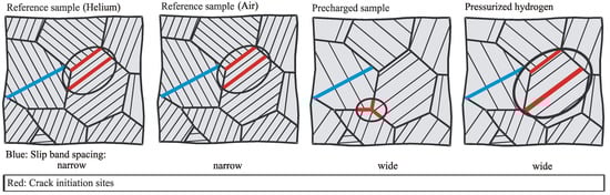
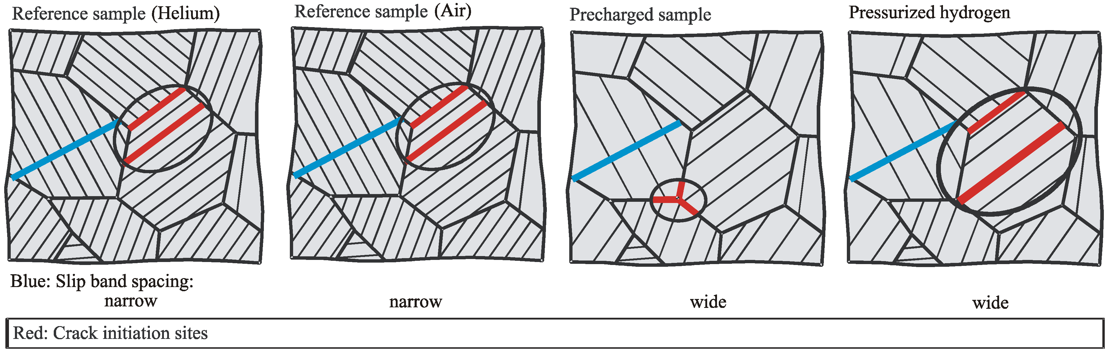
Figure 7.
Crack initiation sites and slip band spacing in reference samples (pressurized helium and air), precharged samples and pressurized hydrogen samples.
An evaluation of the slip bands formed around the crack shows clear differences. Thus, the average distance of the slip bands in the X2–12-H2 samples is 4.7 μm, in the case of the reference samples only 1.92 μm. While the minimum heights of the slip bands are identical, they can emerge significantly further from the surface in X2–12-H2 samples (0.14 μm to 0.08 μm). This effect was also shown by Aubert et al. and Gangloff [28,29] at the stainless steel AISI 316L. Robertson also shows in [30] at a AISI 310s stainless steel that an increase of hydrogen precharge, leads to the formation of higher slip bands. This behavior suggests that the present hydrogen leads to a localization of plastic deformation. The formation of higher slip bands indicates the HELP mechanism, which reduces the yield stress that allows easier dislocation movement. In the case of precharged specimen, short cracks propagate strongly alternatingly through the grains, while short cracks in reference samples follow without alternating the slip band structure. The short cracks formed in helium samples preferably pass through the glide planes of one grain after initiation and form cracks simultaneously in several adjacent grains at the same vertical stress level, see Figure 8. Depending on the grain orientation, alternating slip occurs between the slip systems. Only in later transcrystalline crack growth do the short cracks grow through grain boundaries due to coalescence, which can also be observed during crack stage II.
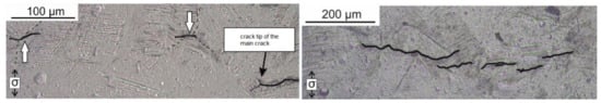
Figure 8.
X2–12, Helium: Short cracks before grain boundaries cross coalescence; Crack initiation of multiple short cracks in front of the crack tip [31].
The EBSD analysis (Figure 9) shows stronger localized formed martensite around the crack at the precharged sample, while in reference samples, larger martensite areas were formed in the surrounding microstructure. In contrast, no significant martensite formation occurred in the specimen tested in compressed hydrogen. Roth [13] also detected this very local martensite formation in a metastable austenitic stainless steel (1.4307) without hydrogen influence. Despite the austenite-stabilizing effect of the high nickel content of the X2–12, martensite formation occurs, which does not develop globally but can only be found in places of high plastic deformation. The lower martensite formation compared to reference samples, according to Murakami et al. [3], can be explained by the hydrogen precharging or the pressurized hydrogen atmosphere and the associated hydrogen effects (HELP). After fatigue tests with an austenitic stainless steel (1.4401) in pressurized hydrogen, the authors showed clearly localized martensite formation in the plastic zone around the crack tip and concluded that the hydrogen content restricted the deformation locally, which is necessary for the martensite formation.
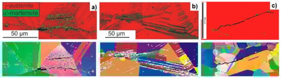
Figure 9.
X2–12, EBSD images of the phase distribution and microstructure of (a) a crack in a precharged sample, (b) a crack in a reference (air) sample and (c) a crack in a pressurized hydrogen sample.
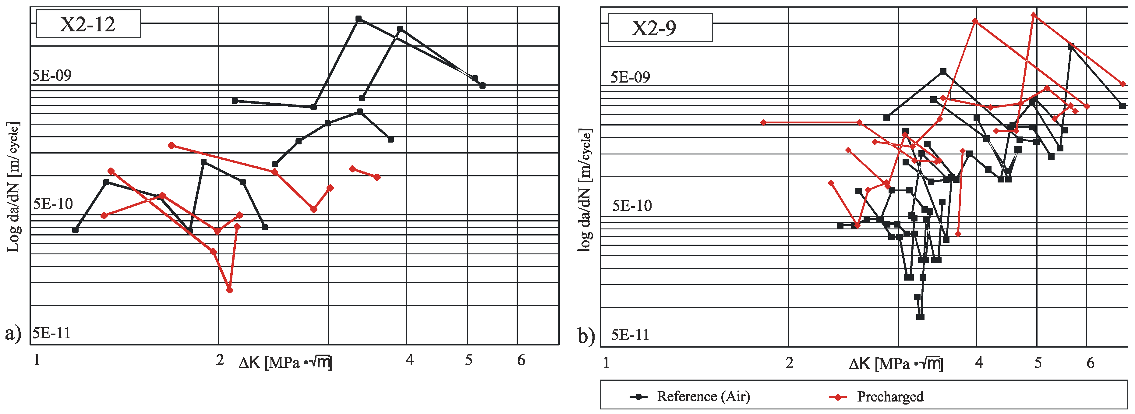
In order to compare the crack growth of X2–9 and X2–12 with different stress levels, the results of the fatigue tests were summarized in the da/dN-ΔK diagrams in Figure 10. Both stainless steels had similar da/dN values in the observed ΔK range; however, the curves allowed different statements about the crack growth mechanisms. The oscillating curves corresponded to the expectation of short crack growth curves according to the literature [13], since the propagation behavior of microstructural short cracks expresses a strong interaction with the microstructure features (such as grain and phase boundaries).
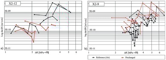
Figure 10.
da/dN—ΔK curves of (a) X2–12 and (b) X2–9; measured on precharged samples (red) and reference (air) samples (black).
For the X2–9, it can be observed that both at low and higher ΔK values, the curves of the precharged samples showed higher da/dN values, and thus the short crack growth accelerated due to hydrogen. In addition, the curves of the X2–9 reference samples showed a greater dependence on microstructural barriers, especially at lower ΔK values, which was reflected in slower crack growth rates. In contrast, the precharged X2–9 curves showed a reduced barrier effect, which increased the crack growth rate. These observations can be clearly explained by the HELP mechanism, as this locally promotes the dislocation movement.
There wa no clear tendency for a hydrogen effect on the short crack propagation for the X2–12 samples, compared to the X2–9. However, some specimen showed even slower crack growth. This can be explained by a change in the crack growth mechanism from single to alternating slip, which occurs earlier under hydrogen. Furthermore, it is known from the literature [32] that austenitic stainless steels have a reduction in hydrogen susceptibility with an increasing of the nickel content.
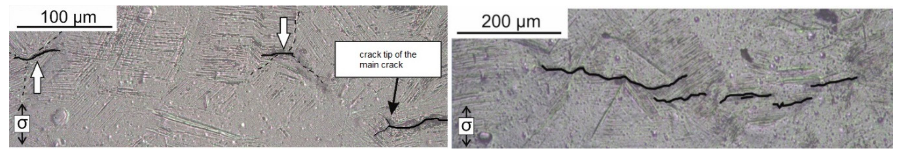
The crack morphologies in the compared samples differed greatly from each other after crack initiation (crack length less than 100 μm). From a macroscopic point of view, the significantly lower crack opening of the precharged X2–12 samples is noticeable compared to the reference samples, which suggests a more localized plasticization. While cracks in the reference specimens grow on one slip system for a long time, in precharged X2–12 specimens multiple slip systems are activated immediately after crack initiation and an alternating crack propagation occurs. This behavior suggests that local stored hydrogen promotes the activation of multiple slip systems directly in front of the crack tip. As a result, hydrogen appears to suppress the typical cracking stage I (single slip) and allows an earlier transition to stage Ib (alternating slip) compared to reference samples (see [33]).
4.2. Investigations on the Martensitic Stainless Steel X3
The following section presents the fatigue behavior of the material X3 under different atmospheres and in different hydrogen precharge conditions. The experiments were carried out with uncharged reference samples in helium atmosphere (10 MPa), in vacuum, in laboratory air and in 10 MPa pressurized hydrogen as well as with precharged samples at laboratory air.
The short cracks in the X3 initiated under helium, vacuum, and laboratory air at martensite needle boundaries. The respective crack morphologies revealed a clear atmospheric influence. Cracks in helium and vacuum were less branched than in uncharged and precharged samples at laboratory air (Figure 11). Both, the uncharged and vacuum-tested samples showed an almost intercrystalline crack morphology, while the cracks in the precharged samples mostly showed a transcrystalline morphology.
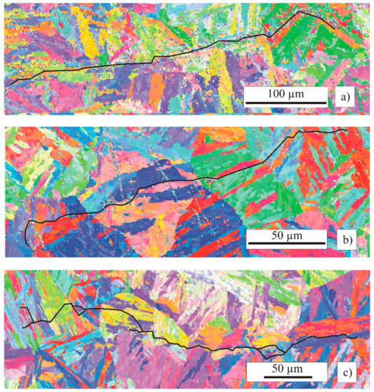
Figure 11.
EBSD scan of X3 specimen: (a) in vacuum (75.000 cycles), (b) at laboratory air (50.000 cycles) and (c) precharged (40.000 cycles).
With increasing number of cycles, the uncharged samples in helium and laboratory air and the hydrogen-loaded samples in air form an increasing number of cracks, which coalesce after exceeding a respective crack length of about 150 µm. In particular, the long-crack growth is characterized by a discontinuous crack growth behavior. However, even with short cracks with a length of <250 μm, this behavior could be observed in helium. Obviously, a vertical offset of the short cracks is more easily overcome compared to the X2–12 or X2–9. The reason for this is the needle-like structure of martensite. If the martensite needles lay perpendicular to the crack, the propagation in the stress direction can be simplified. In vacuum, only a few cracks initiate and grow without coalescence.
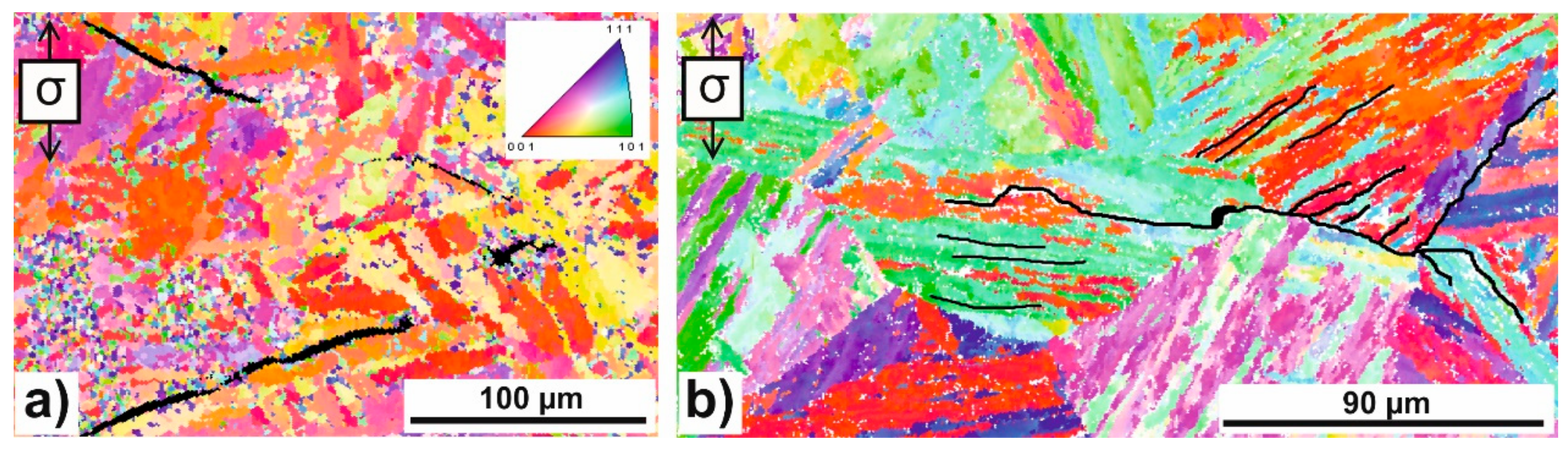
The fatigue tests on uncharged samples in 10 MPa hydrogen showed a significantly changed crack initiation behavior compared to experiments in helium. In hydrogen, martensitic needle boundaries oriented between 45° and 90° to the principal stress were the preferred initiation sites. The cracks grow parallel to each other along the martensite needle boundaries. In helium, there were no regiments of parallel short cracks, and crack growth was slowed down when a grain boundary was reached. The crack growth behavior was influenced by microstructural conditions such as grain size and orientation. Figure 12 shows crack propagation stage II after a short crack has formed on a former austenitic grain boundary.

Figure 12.
EBSD scan of uncharged X3 specimen: (a) in pressurized helium and (b) in pressurized hydrogen [28].
Due to their crystal misorientation, the martensitic needle boundaries represent hydrogen traps. This local hydrogen accumulation promotes crack initiation [25]. Despite the stress shadow of the first initiated short crack, hydrogen can cause further cracks in the immediate vicinity. It can be assumed that large misorientation between two martensite needles could absorb more hydrogen, resulting in a simplified crack initiation.
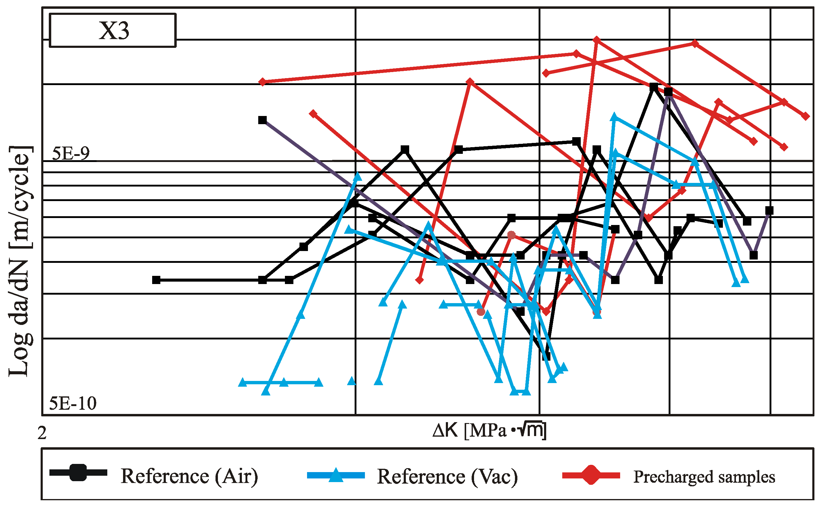
The results from the fatigue tests with the X3 are summarized in the da/dN over ΔK diagram in Figure 13. As in the case of the X2–9 and X2–12 samples, an oscillating curve was also evident here, as expected from the literature and from the EBSD investigations presented. It can be observed that at both lower and higher ΔK values, the precharged samples showed higher da/dN values and less of a barrier effect than the vacuum and laboratory air samples, thus the hydrogen cracking was significantly accelerated and tended to increase faster. This shows both an influence of atmosphere and hydrogen. The accelerated crack growth can be explained by the HEDE mechanism, which locally reduces the binding forces of martensite needle boundaries and allows a faster cracks growth.
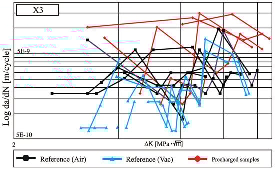
Figure 13.
Crack growth rate of precharged specimens (5 wppm) and reference specimens (Air, vacuum) of the X3, R = −1, Δσ/2 = 640 MPa (Vac), Δσ/2 = 665 MPa (Air, precharged).
4.3. Conclusion Experimental Results
Basically, differences in crack initiation sites as well as crack growth among the various atmospheric influences can be seen. Comparing the crack initiation sites in the X2–12, it is found that cracks are initiated at grain boundary triple points on hydrogen-precharged samples, as well as on uncharged samples of helium below 10 MPa. In case of reference samples at laboratory air, cracks occur both at slip bands and at grain boundaries. This difference can be explained by the decohesive effect of the invading foreign atoms, which indicates the embrittlement mechanism HEDE.
The test results confirm that X2–12 is less susceptible to hydrogen embrittlement due to its high nickel content and thus its stable austenite phase. If, on the other hand, the crack growth behavior is considered more closely, the influence of hydrogen becomes more apparent. At the first stage of crack growth in hydrogen precharged samples, cracks are preceded by alternately sliding several slip systems in front of the crack tip (stage Ib). In contrast, cracks in uncharged samples grow in vacuum and air after crack initiation by single slip (stage Ia, which corresponds to the classical stage I). The results of local martensite formation in front of the crack tip show that neither in air nor in hydrogen can a significant phase transformation be detected. However, hydrogen is expected to significantly affect the strain-induced transformation of γ-austenite to α′-martensite.
Due to the lower stacking fault energy of the X2–9 as a result of the lower nickel content, the deformation-induced martensite formation is strongly favored, and thus a pronounced effect on the short crack propagation can be expected. The results of the X2–9 above support the assumption and show a significant influence of hydrogen on crack initiation and propagation. Cracks in precharged specimens grow much faster than in reference specimens and show little dependence on the local microstructure.
In the martensitic stainless steel X3, which was also examined, the observed cracks in all atmospheres and hydrogen contents initiated only at martensitic needle boundaries. Compared to the steel X2–12, which also causes cracks in slip bands at laboratory air, the formation of slip bands and thus the presence of micro-grooves is absent. Crack growth in uncharged samples in pressurized hydrogen and hydrogen-precharged samples is transcrystalline. In uncharged samples at air and in vacuum, intercrystalline crack growth occurs. The changed short crack morphologies can be explained by the high dislocation density in the martensite, by which the hydrogen attaches not only preferentially at the grain boundaries, but also within the needles. As a result, the crack growth is no longer characterized by the position of the grain boundaries, but by the locally present hydrogen content. With regard to the crack growth rates, a strong influence of the atmosphere and hydrogen can be identified.
5. Results on the Simulation of Short Crack Propagation in a Metastable Austenitic Stainless Steel X2CrNi19-12
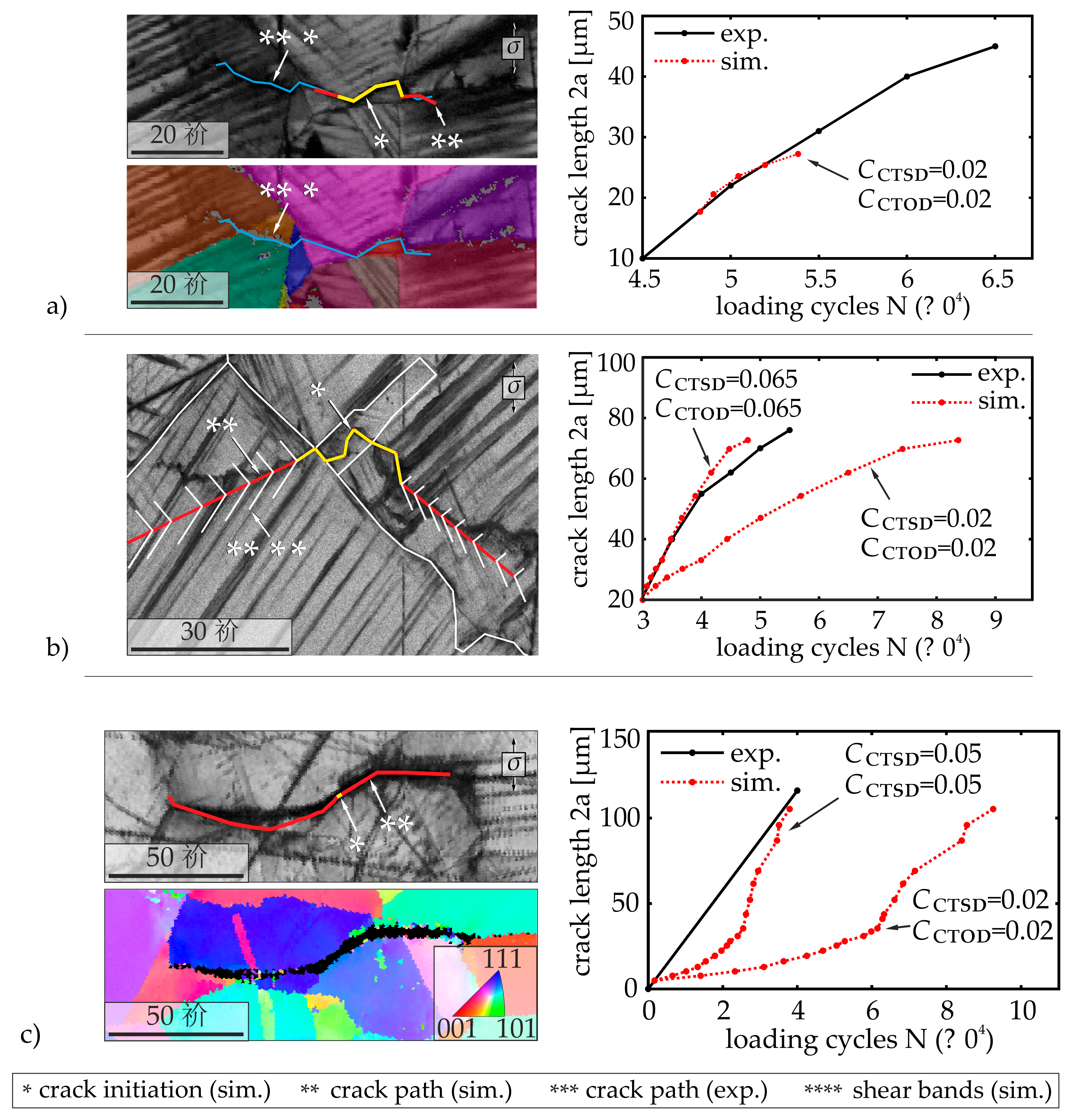
From the previously presented experimental investigations on the specimens of the X2–12, the change of the short crack propagation behavior was characterized and explained by the HELP mechanism. The simulation results given in the following, illustrates the crack propagation behavior on the basis of the presented modelling concepts and further lead to additional conclusions on the effect of hydrogen. In Figure 14, the simulation results for the short crack propagation in real microstructures in an uncharged specimen, in a precharged specimen, and in an uncharged specimen in 10 MPa hydrogen atmosphere are shown. In addition to the crack morphology, the crack length with respect to the loading cycles were compared with experimentally obtained results. The input parameters for the simulation are defined as = 108 MPa and = 80 MPa according to [8] and [15] and the cyclic yield stress was assumed as = 410 MPa.

Figure 14.
Scanning electron microscopy (SEM)- and EBSD-images of the crack path and comparison of the predicted crack growth with experimentally obtained results on specimens of X2–12 (a) in an uncharged specimen (R = −1, Δσ/2 = 365 MPa), (b) in a precharged specimen (R = −1, Δσ/2 = 365 MPa, cH = 40 wppm) and (c) in an uncharged specimen tested in 10 MPa hydrogen atmosphere (R = −1, Δσ/2 = 270 MPa).
At first, the simulation results were compared with the experimental investigations on the uncharged specimen (Figure 14a) in order to obtain the constants from the crack growth laws according to Equations (4) and (5). It can be seen that the predicted crack path coincides with the observed crack from the fatigue test. By further comparing the calculated crack length over the loading cycles, the exponents = = 1 and the irreversibility constants = = 0.02 could be obtained. These constants are of the same order of magnitude as in the metastable austenitic stainless steel X2CrNi18-9 (C = 0.018) investigated in [8]. Based on these results, the short crack propagation behavior under the influence of hydrogen was further investigated, see Figure 13b,c. For the precharged specimen as well as the uncharged specimen in 10 MPa hydrogen atmosphere, it can be seen that to accurately predict the short crack propagation, the irreversibility constants are determined as = = 0.065 respectively and = = 0.05, which are significantly higher than in the uncharged specimen. It should also be noted that the results from the simulations according to Figure 13c are based on a conservative assumption of the number of cycles for crack initiation with N = 0, as this could not accurately be detected in the experiments. As a result, the influence of hydrogen is underestimated. Nevertheless, the effect on the crack growth is clearly visible. Furthermore, to correctly predict the experimentally observed crack path in Figure 14c, it was necessary to decrease the critical normal stress for grain boundary cracking in the presence of hydrogen.
With these results, the mechanisms of short crack propagation under the influence of hydrogen in X2–12 can be derived from the point of view of the modelling approaches and compared with the experimental investigations. From the increasing irreversibility constants C in precharged and uncharged samples in 10 MPa hydrogen atmosphere, the following hydrogen influences can be concluded. Based on the model proposed by Wilkinson [13], the irreversibility constant C is a measure of the irreversible part of the plastic deformation at the crack tip. The increasing irreversible plastic deformation in the presence of hydrogen can be explained by the locally increasing mobility of dislocations due to the accumulation of hydrogen at the crack tip according to the HELP model. In contrast to this explanation, the postulated influence of hydrogen on facilitating the formation of vacancies according to the hydrogen-enhanced strain-induced vacancies (HESIV) model [34] could also explain the effect of hydrogen on the increasing irreversible deformation processes at the crack tip. Another explanation for the observed effect in the simulation is that hydrogen could lead to facilitated emission of dislocations at the crack tip. These mechanisms could separately explain the increased irreversibility. Nevertheless, the observed increased slip band height in the presence of hydrogen (see Figure 7) indicates the HELP mechanism may be predominant in precharged specimens. In the specimens tested in 10 MPa hydrogen atmosphere, grain boundary cracking is facilitated which supports the HEDE mechanism acting at grain boundaries.
The presented simulation results also validate the physically based modelling approaches. In [8], only a good agreement of the predicted crack path with the experimentally determined crack path could be established, if the slip plane of the activated slip systems at the crack tip is in the normal direction to the sample surface. This restricting condition has been significantly improved with the new modelling approaches.
In addition to the simulations presented here, results were presented in [35] that show a predicted crack path considering the martensitic phase transformation at the crack tip in a precharged specimen taking into account the local hydrogen concentration in the microstructure. It was shown that the model can qualitatively reproduce the martensitic phase transformation, which further confirmed the applied modelling concepts.
6. Conclusions
The results of in-situ fatigue tests were presented, which were performed on two metastable austenitic stainless steels and one martensitic stainless steel at a test frequency of 1 Hz under alternating tensile and compressive stress in the LCF/HCF transition regime. The focus of the investigation was on the characterization of hydrogen mechanisms that influence crack initiation and short crack propagation.
It could be shown for the crack morphology and the crack length over cycles that with increasing nickel and martensite content an increased susceptibility to hydrogen effects occurs. For the X2–12 samples, there is only a macroscopic change in the crack characteristics under the influence of hydrogen; the crack propagation is hardly affected. With a higher nickel and martensite content, the X2–9 is much more susceptible. Here, the present hydrogen influences the crack propagation. With regard to the martensitic samples X3, the highest possible influence of hydrogen and atmosphere is shown. Precharged samples show a significantly higher crack growth rate and a significantly lower tendency to oscillating curves. Microstructurally small cracks grow in hydrogen-precharged samples with. The altered crack propagation can be explained by a reduced barrier effect of microstructural barriers, which is facilitated by a facilitated dislocation motion through the HELP mechanism.
The presence of hydrogen causes a change in the type of crack initiation and in the slip band morphology, depending on the hydrogen content. Thus, in reference samples, crack initiation occurs at slip bands and grain boundaries (transgranular crack initiation), whereas in hydrogen precharged samples, crack initiation occurs at large microstructural defects such as grain boundary triple points (intergranular crack initiation) what can be explained by the HEDE mechanism.
For the X3, the crack morphology changes from transgranular to intergranular crack propagation in the precharged samples, due to the hydrogen content and hydrogen effects (HELP) compared to the reference samples. In summary, the larger the martensitic phase, the higher the increase in hydrogen crack growth rate.
The simulation results showed that the presented model is able to predict the experimentally observed crack morphology and the crack growth behavior in a metastable austenitic stainless steel and thus validates the proposed approaches for describing short crack propagation. The simulation results in precharged specimen further supports the acting HELP mechanism during short crack growth. This is concluded based on the investigated increased irreversible plastic deformations at the crack tip. In specimens tested in 10 MPs hydrogen atmosphere, it could be found that hydrogen also facilitates grain boundary cracking.
Author Contributions
S.B. performed the fatigue tests and analyses of the reference specimens (air, vaccum, precharged), M.S. performed the fatigue tests and analyses in pressurized helium and hydrogen and V.S. performed the simulation part. H.-J.C., C.-P.F. and S.W. contributed by scientific discussions and by reviewing the paper.
Acknowledgments
The authors wish to thank Deutsche Forschungsgemeinschaft (DFG) and Forschungsvereinigung Verbrennungskraftmaschinen e.V. (FVV) for the financial support of this research project titled Fatigue life reduction of steels in pressurized hydrogen as a consequence of changes in small crack propagation mechanisms (Reference numbers CH92/48-1 (DFG) and 1185 (FVV)).
Conflicts of Interest
The authors declare no conflicts of interest.
References
- Nibur, K.A.; Gibbs, P.J.; Foulk, J.W.; SanMarchi, C. Notched Fatigue of Austenitic Alloys in Gaseous Hydrogen. In Proceedings of the ASME 2017 Pressure Vessels and Piping Conference Volume 6B: Materials and Fabrication, Waikoloa, HI, USA, 16–20 July 2017. [Google Scholar]
- Takakuwa, O.; Yamabe, J.; Matsunaga, H.; Furuya, Y.; Matsuoka, S. Recent Progress on Interpretation of Tensile Ductility Loss for Various Austenitic Stainless Steels with External and Internal Hydrogen. In Proceedings of the ASME 2017 Pressure Vessels and Piping Conference Volume 6B: Materials and Fabrication, Waikoloa, HI, USA, 16–20 July 2017. [Google Scholar]
- Murakami, Y.; Kanezaki, T.; Mine, Y. Hydrogen Effect against Hydrogen Embrittlement. Metall. Mater. Trans. 2010, 41, 2548–2562. [Google Scholar] [CrossRef]
- Skipper, C.; Leisk, G.; Saigal, A.; San Marchi, C. Effect of internal hydrogen on fatigue strength of type 316 stainless steel. In Proceedings of the 2008 International Hydrogen Conference, Grand Teton National Park, WY, USA, 7–10 September 2008; Somerday, B., Sofronis, P., Jones, R., Eds.; ASME Press: New York, NY, USA, 2009; pp. 139–146. [Google Scholar]
- San Marchi, C.; Michler, T.; Nibur, K.A.; Somerday, B.P. On the physical differences between tensile testing of type 304 and 316 austenitic stainless steels with internal hydrogen and in external hydrogen. Int. J. Hydrog. Energy 2010, 35, 9736–9745. [Google Scholar] [CrossRef]
- Yagodzinski, Y.; Saukkonen, T.; Andronova, E.; Rissanen, L.; Hänninen, H. Hydrogen-induced cracking of metastable austenitic stainless and high-strength carbon steels. In Proceedings of the 2008 International Hydrogen Conference, Moran, WY, USA, 7–10 September 2008; Somerday, B., Sofronis, P., Jones, R., Eds.; ASME Press: New York, NY, USA, 2009; pp. 123–130. [Google Scholar]
- Künkler, B. Mechanismenorientierte Lebensdauervorhersage unter Berücksichtigung der Mikrostruktur—Modellentwicklung, Verifikation und Anwendung. Dissertation, Universität Siegen, Siegen, Germany, 2007. [Google Scholar]
- Kübbeler, M. Simulation der Mikrostrukturbestimmten Kurzrissausbreitung unter dem Einfluss Lokaler Phasenumwandlung. Dissertation, Universität Siegen, Siegen, Germany, 2017. [Google Scholar]
- Tabata, T.; Birnbaum, H.K. Direct observations of the effect of Hydrogen on the behaviour of dislocations in iron. Scr. Metall. 1983, 17, 947–950. [Google Scholar] [CrossRef]
- Oriani, R. A mechanistic theory of hydrogen embrittlement of steels. Phys. Chem. 1972, 76, 848–857. [Google Scholar]
- Petch, N.J.; Stables, P. Delayed Fracture of Metals under Static Load. Nature 1952, 169, 842–843. [Google Scholar] [CrossRef]
- Lynch, S.P. Mechanisms of hydrogen assisted cracking—A review. In Proceedings of the International Conference on Hydrogen Effects on Material Behaviour and Corrosion Deformation Interactions, Moran, WY, USA, 22–26 September 2002; pp. 449–466. [Google Scholar]
- Roth, I. Untersuchungen zum Ausbreitungsverhalten Mikrostrukturell kurzer Ermüdungsrisse in Metastabilem Austenitischen Edelstahl. Dissertation, Universität Siegen, Siegen, Germany, 2012. [Google Scholar]
- Brück, S.; Schippl, V.; Schwarz, M. Untersuchung des Einflusses einer Wasserstoffvorbeladung auf die Ermüdungskurzrissausbreitung in einem austenitischen Edelstahl. In Tagungsband zur Werkstoffprüfung; Borsutzki, M., Düsseldorf, G., Eds.; Moninger: Karlsruhe, Germany, 2015. [Google Scholar]
- Hilgendorff, P.-M. Mechanismenbasierte Modellierung und Simulation des VHCF-Wechselverformungs-Verhaltens Austenitischer Edelstähle. Dissertation, Universität Siegen, Siegen, Germany, 2017. [Google Scholar]
- Wilkinson, A.J.; Roberts, S.G. A dislocation model for the two critical stress intensities required for threshold fatigue crack propagation. Scr. Mater. 1996, 35, 1365–1371. [Google Scholar] [CrossRef]
- Olson, G.B.; Cohen, M. A mechanism for the strain-induced nucleation of martensitic transformation. J. Less Common Met. 1972, 28, 107–118. [Google Scholar] [CrossRef]
- Köster, P. Mechanismenorientierte Modellierung und Simulation der Mikrostrukturbestimmten Kurzrissausbreitung unter Berücksichtigung ebener und Räumlicher Aspekte. Dissertation, Universität Siegen, Siegen, Germany, 2015. [Google Scholar]
- Rios, E.R.; Sun, Z.Y.; Miller, K.J. A theoretical and experimental study of environmental hydrogen-assisted short fatigue crack growth in an Al-Li alloy. Fatigue Fract. Eng. Mater. Struct. 1994, 17, 1459–1474. [Google Scholar] [CrossRef]
- Von Pezold, J.; Lymperakis, L.; Neugebauer, J. Hydrogen-enhanced local plasticity at dilute bulk H concentrations: The role of H–H interactions and the formation of local hydrides. Acta Mater. 2011, 59, 2969–6980. [Google Scholar] [CrossRef]
- Kotake, H.; Matsumoto, R.; Taketomi, S.; Miyazaki, N. Transient hydrogen diffusion analyses coupled with crack-tip plasticity und cyclic loading. Int. J. Press. Vessels Pip. 2008, 85, 540–549. [Google Scholar] [CrossRef]
- Li, J.C.M.; Oriani, R.A.; Darken, L.S. The Thermodynamics of Stressed Solids. Z. Phys. Chem. 1966, 49, 271–290. [Google Scholar] [CrossRef]
- Brooks, A.N.; Hughes, T.J.R. Streamline Upwind Petrov-Galerkin Formulation for Convection-Dominated Flows with Particular Emphasis on the Incompressible Navier-Stokes Equations. Comput. Methods Appl. Mech. Eng. 1982, 32, 199–259. [Google Scholar] [CrossRef]
- Navarro, A.; de los Rios, E.R. Short and long fatigue crack growth—A unified model. Philos. Mag. A 1988, 57, 15–36. [Google Scholar] [CrossRef]
- Müller-Bollenhagen, C.; Zimmermann, M.; Christ, H.-J. Very high cycle fatigue behaviour of austenitic stainless steel and the effect of strain-induced martensite. Int. J. Fatigue 2010, 32, 936–942. [Google Scholar] [CrossRef]
- Ratte, E. Wasserstoffinduzierte verzögerte Rissbildung austenitischer Stähle auf CrNi(Mn)- und Mn-Basis. Dissertation, Universität Aachen, Aachen, Germany, 2007. [Google Scholar]
- Kramer, D.; Brager, H.R.; Rhodes, C.G.; Pard, A.G. Helium embrittlement in type 304 stainless steel. J. Nucl. Mater. 1968, 25, 121–131. [Google Scholar] [CrossRef]
- Aubert, L.; Saintier, N.; Olive, J.M. Crystal plasticity computation and atomic force microscopy analysis of the internal hydrogen-induced slip localization on polycrystalline stainless steel. Scr. Mater. 2012, 66, 698–701. [Google Scholar] [CrossRef]
- Gangloff, R.P. Gaseous Hydrogen Embrittlement of Materials in Energy Technologies; Woodhead Publishing: Sawston, UK, 2012; ISBN 978-1-84569-677-1. [Google Scholar]
- Robertson, I.M.; Lillig, D.; Ferreira, P.J. Revealing the fundamental processes controlling hydrogen embrittlement. In Proceedings of the 2008 International Hydrogen Conference, Grand Teton National Park, WY, USA, 7–10 September 2008; Somerday, B., Sofronis, P., Jones, R., Eds.; ASME: New York, NY, USA, 2009; pp. 22–37. [Google Scholar]
- San Marchi, C.; Somerday, B. Technical Reference for Hydrogen Compatibility of Materials; Sandia Report SAND2012-7321; Sandia National Laboratories: Albuquerque, NM, USA, 2012.
- Düber, O. Untersuchungen zum Ausbreitungsverhalten Mikrostrukturell kurzer Ermüdungsrisse in Zweiphasigen Metallischen Werkstoffen am Beispiel eines Austenitisch-Ferritischen Duplexstahls. Dissertation, Universität Siegen, Siegen, Germany, 2007. [Google Scholar]
- Schwarz, M.; Brück, S.; Schippl, V.; Zickler, S.; Weihe, S. Hydrogen influence on fatigue life and short crack growth of X3CrNiMo13-4 and modified X2Crni19-11. In Proceedings of the 2016 International Hydrogen Conference, Materials Performance in Hydrogen Environment, Grand Teton National Park, MY, USA, 11–14 September 2016; Somerday, B.P., Sofronis, P., Eds.; ASME Press: New York, NY, USA, 2017; pp. 263–269. [Google Scholar]
- Nagumo, M.; Nakamura, M.; Takai, K. Hydrogen thermal desorption relevant to delayed-fracture susceptibility of high-strength steels. Metall. Mater. Trans. A 2001, 32, 339–347. [Google Scholar] [CrossRef]
- Schippl, V.; Brück, S.; Fritzen, C.-P.; Christ, H.-J.; Schwarz, M.; Weihe, S. Numerical simulation of the influence of hydrogen on small fatigue crack growth mechanisms in AISI304L. In Proceedings of the 2016 International Hydrogen Conference, Materials Performance in Hydrogen Environment, Grand Teton National Park, MY, USA, 11–14 September 2016; Somerday, B.P., Sofronis, P., Eds.; ASME Press: New York, NY, USA, 2017; pp. 620–627. [Google Scholar]


© 2018 by the authors. Licensee MDPI, Basel, Switzerland. This article is an open access article distributed under the terms and conditions of the Creative Commons Attribution (CC BY) license (http://creativecommons.org/licenses/by/4.0/).