Article

Optimizing the Gating System for Steel Castings †

Department of Foundry Engineering, Silesian University of Technology, 44-100 Gliwice, Poland
*
Author to whom correspondence should be addressed.
This paper is a revised and expanded version of a paper titled Cast steel—a fresh look at the potential and future which was presented at the 5th International Conference on Modern Manufacturing Technologies in Industrial Engineering ModTech 2017, 14–17 June 2017, Sibiu, Romania.
Metals 2018, 8(4), 266; https://doi.org/10.3390/met8040266
Submission received: 17 March 2018 / Revised: 4 April 2018 / Accepted: 10 April 2018 / Published: 13 April 2018
(This article belongs to the Special Issue Optimization of Industrial Casting Processes)

Abstract

:
The article presents the attempt to optimize a gating system to produce cast steel castings. It is based on John Campbell’s theory and presents the original results of computer modelling of typical and optimized gating systems for cast steel castings. The current state-of-the-art in cast steel casting foundry was compared with several proposals of optimization. The aim was to find a compromise between the best, theoretically proven gating system version, and a version that would be affordable in industrial conditions. The results show that it is possible to achieve a uniform and slow pouring process even for heavy castings to preserve their internal quality.

1. Introduction

Cast steel comprises a group of alloys that are widely known and have been used for many years in various industrial applications. The articles [1,2,3] present the statistical data and the forecast for the foundry industry in Poland and the rest of the world, showing that the steel castings are still popular and useful. Most heavy casting was made from cast steel, including the heaviest castings that were ever cast for hydraulic presses, forging hammer frames, or parts for offshore energy facilities for example the heavy hydro turbine blades [4,5,6,7,8]. This was due to the superior properties of many cast steel grades and the possibility of being able to tailor the properties to specific conditions with heat treatment or surface engineering [9,10,11], bi-metallic casting production, including welding techniques, etc. [12,13,14]. However, because the sector of iron castings production is growing because of new developments and improvements, and due to cheaper prices for cast iron grades, such as ductile iron, ADI (Austempered Ductile Iron), or CGI (Compacted Graphite Iron, the so-called vermicular iron), cast steel is considered to be an obsolescent material. In [15], the use of the wear resistant Fe-C-Cr alloys have been proposed instead of some steel castings. The article [16] shows the method of cheap ductile iron production on the base of steel scrap, while the authors of [17,18] presented the high-silicon cast iron and SiMo iron capabilities and advantages. The authors of [19,20,21] thoroughly described the outstanding properties of the CGI iron while comparing it with the Ductile Iron (DI). The properties of the modern ADI grades and their capability to replace the steel castings in some applications have been presented in [22,23]. Yearly production of steel castings oscillates at ca. 10–11% worldwide, whereas in some countries, including Poland, the production rate is only ca. 5–6% [1]. In recent years, a new shift has started and the trend to return to cast steel grades has returned along with some developments in metallurgy and casting mold technology [24,25]. This article focuses on steel casting mold design and particularly on the issue of the gating system, as it is necessary to follow a strict technological regime, regarding not only molten alloy purity to achieve the best casting quality. An incorrectly performed mold pouring process via a poorly designed gating system can result in re-oxidation and in the appearance of small mold damages with a final internal defect (non-metallic inclusions acting as small cracks, excessive gas porosity) [26,27,28,29,30]. Research studies regarding the above phenomena were conducted by many scientists, yet John Campbell’s theory of bi-film and the ‘ten rules of casting’ have had one of the most important impacts, and have been described, among others, in [31,32,33,34,35,36]. The theory and practice regarding the gating system constitute an extensive topic and many different approaches and proposals have been recommended. The issue has been developed and solutions proposed, although the issue is still open to discussion. Every casting, particularly a single heavy one that is designed and manufactured from scratch, is a completely new and demanding object. Thus, the gating system must be developed for each specific shape, size, wall thickness, alloy, etc. There is no place for mistakes when only one or a few identical castings are being produced, thus the most sophisticated procedures and tools should be used.

2. Materials and Methods

It is common knowledge that the molten metal velocity should equal approximately 0.5 m/s to ensure a proper (not too slow and not too fast) mold cavity filling process [33]. Yet, this is very difficult or is sometimes nearly impossible under normal gravity pouring conditions when using a simple, old-fashioned gating system. Thus, a special gating system design is crucial, although simple channel cross-section changes are not enough to significantly change the character of the metal flow [24,37,38,39]. In the presented research, authors resigned from implementing offset pouring basin, gating systems will be filled using contact pouring method, as it allows for isolating the metal from the surrounding atmosphere [31]. The experiments that are described in this article constitute the computer modelling part of a large experimental plan to develop a scientifically optimized and practically useful molding technology for heavy (up to 25–30 tons) steel castings. The foundry plant where the industrial part of the research will be completed in the near future cannot achieve better performance due to an excessive level of internal and surface defects. At present, both the internal and surface quality of the castings are too often outside the specifications, and there is significant evidence to show that the reason might be improper pouring process control. Thus, this problem has both scientific and practical meaning. Several gating system designs were examined for model simple casting, which is a typical clover-like sample whose geometry is shown in Figure 1. This sample is used as an obligatory cast for every melt in the steel foundry to check the main mechanical properties; its quality is nearly as important as the real casting quality. Moreover, the gating system that is used for the sample is more or less the same as those that will be used in actual production.
The modelling was conducted on two popular and well-known computer packages, namely NowaFlow & Solid (ver. CV 4.4r2, NovaCast Systems AB, Ronneby, Sweden) and MagmaSoft® (ver. 5.0, MAGMA Giessereitechnologie GmbH, Aachen. Germany), but the latter was chosen after the trial modelling experiments. The main modelling parameters were the same for all of the experiments, i.e., alloy: low-carbon cast steel GS52 according to Polish norm PN-ISO 3755:1994 and pouring temperature: 1570 °C.

3. Results and Discussion

In this section, the approach to the gating system optimization has been shown, starting with the reference gating system, being in use now in the foundry plant that is subjected to the research.

3.1. Reference Gating System Geometry

The modelling started with the present gating system design, which is based on commercially available ready-to-use refractory elements/bricks combined and set together to the desired shape and lengths of the gating system channels; see Figure 2.
The pouring process is unstable, and the liquid alloy front velocity is far too large. It is highly visible that when the alloy passes through the downsprue, its velocity is higher than 6 m/s and when it reaches the mould cavity it is still ca. 5 m/s, so it is 10× greater than the 0.5 m/s, which is considered as the proper value. That is why we can observe a jet splashing effect and its attack on the mould walls. Molten metal appears to hit the top of the casting geometry and turn. Top of the mold is open and thus the rebounding shown in the bottom row would not occur in real life. The software cannot solve for a control volume not present in the mesh so it makes this free surface act like a mold wall and turns like displayed in the figure. This results from the very dangerous mixing of the liquid alloy with the air that is entrapped in the mould that is then sucked into the mould by the pump effect, as described in [36]. The effect is present when the alloy does not fill the full cross-section of the downsprue, thus producing an air gap between the metal and sprue surface. A visible back wave travelling through the gating system can be noticed; it not only changes the distribution of the metal velocity, but its pressure also results in the further mixing and quality degradation via the formation of oxide biofilms. It can also be noticed that the velocity of the metal is not constant after the gating system is filled, i.e., the velocity changes gradually, thus proving that the flow is turbulent. Current moulding technology in the foundry is based on an analogical method (bottom pouring), so analogical phenomena occur in the castings that are manufactured there. The castings’ cross-sections (during sample cutting from the clover casting) show an elevated level of non-metallic impurities and bubble-like defects. This affects the mechanical properties of the sample and nearly definitely the final castings. Thus, an optimisation exercise was conducted to increase the overall castings quality and to level up the foundry performance.

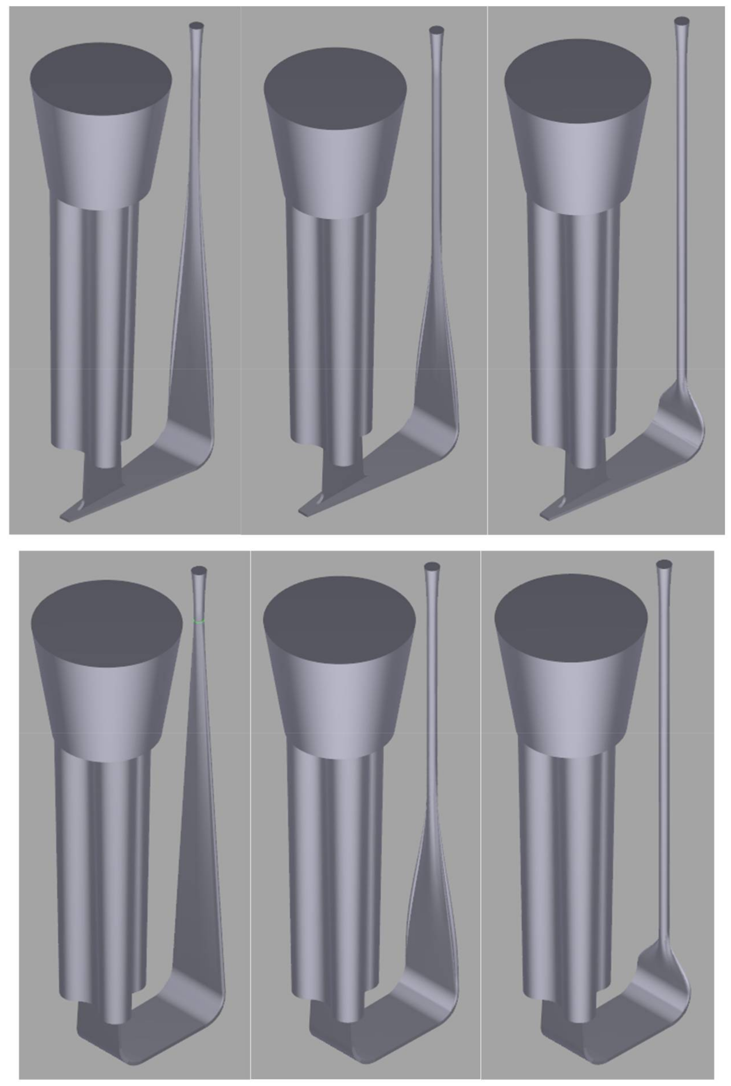
3.2. Gating System Optimization Based on a Re-Design of the Downsprue

A series of modelling experiments was conducted with various (optimised according to different authors’ proposals) gating system modifications, all of which were focused on downsprue tapering in the first stage (see Figure 3).
Nearly all of the bottom-top ladles have circularly shaped nozzles that should constitute the initial shape of a gating system. The tapering of the sprues’ cross-section should change according to the hyperbolic curve, as it depicts the actual nature of the stream [34,35,36]. The authors of this paper noticed in their most recent studies that liquid metal flowing through runners having different shapes and circumference and the same cross-section area tend to behave differently, i.e., the slimmer the runner, the lower the potential metal mixing takes place and the more laminar the flow is, which is why it was decided to study rectangular-shaped runners. The authors examined the transition of the downsprue from a circular to a rectangular shape. The best results were obtained when the transition took place on the longest section possible, i.e., the shorter the length of the transition, the more turbulent the flow. Tests included a triangular ending of the runner with a perpendicular ingate, although this solution increased the jetting effect and created an uneven velocity in the runner, so it was found to be inefficient. Tens of modelling iterations were conducted, but only some of them were selected and representative examples are shown. In the foundry, designers with some knowledge regarding downsprue tapering do indeed try to taper it, but the results will be far from perfect when it is not done properly (see Figure 4).
Even though the liquid alloy velocity is not too poor in the mould cavity entrance (ca. 0.8 m/s), it is observable that the metal flow in the downsprue has no contact with its walls, thus a huge sucking pump effect appears and the gas porosity ratio in the sample casting is high. The aim of the experiments was to achieve a stable, uniform metal flow with a velocity that is no higher than 0.5 m/s during the decisive moments of the pouring process. Thus, further research was done using an increasingly more complex and sophisticated gating system starting with a prolonged runner, vortex gate and spin trap, and ending with a combined trident gate system [24,40,41,42].

3.3. Gating System with a Prolonged Runner

The first attempt was based on the prolonged runner idea, i.e., that the additional part of the runner after the ingate part should act as a brake for the liquid alloy. Yet, for very fast liquid velocity, which is the result of a long downsprue and the dynamics of the ladle bottom pouring system, such a gating design is inefficient (see Figure 5).
It should be noticed that the velocity in the sprue is almost constant, which is a perfect outcome, proving that this design of the downsprue is a vital improvement to the process. When the flow enters the ingate area, its velocity is in the range of 1.2–1.4 m/s, but the additional runner part, which is curved vertically to the top, makes its almost acceptable. However, a turbulent character is still visible when the alloy enters the mold cavity, although this effect can be decreased by increasing the length of the prolonged runner. The process stabilizes after a few seconds (the total filling time is 10 s on average), but the splashes are still too excessive. It must be mentioned that the prolonged runner can be the place for the non-metallic inclusions (oxides, loose sand grains, etc.), capturing some portions of them and improving the internal cleanliness of the casting.

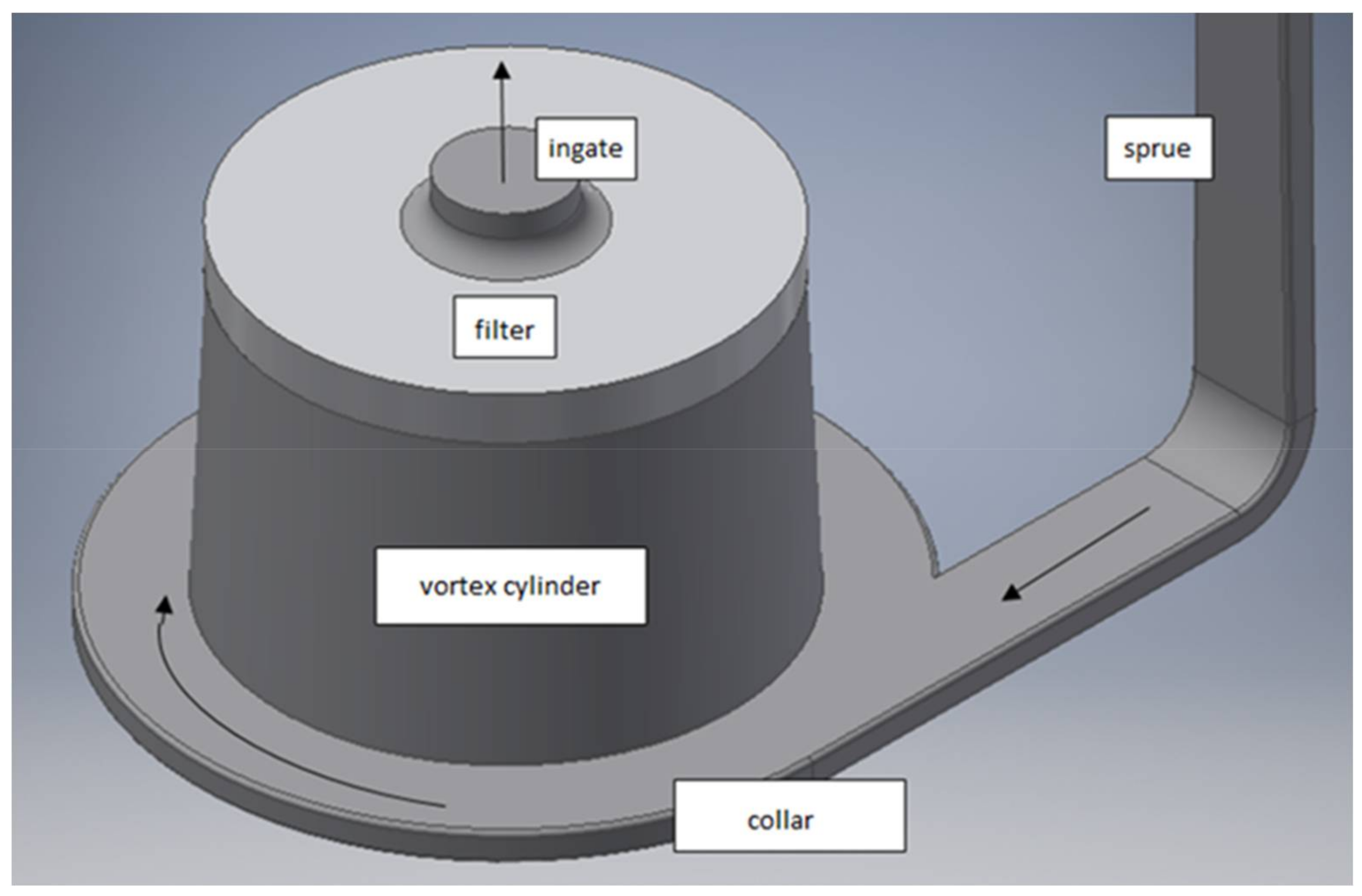
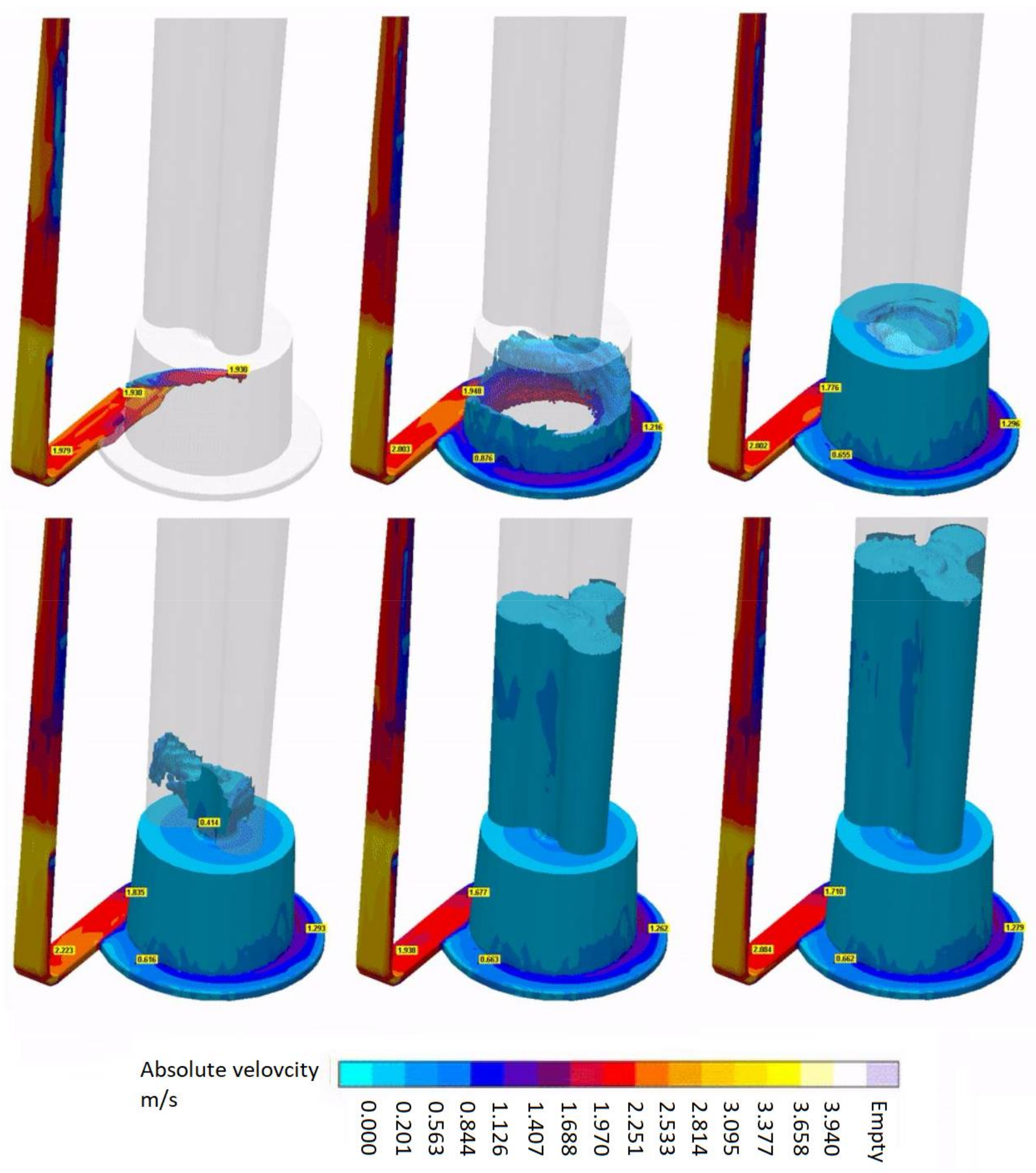
3.4. Vortex Gate System

Another modification that was checked in the experimental procedure concerned the so-called vortex gate, whose concept is presented in Figure 6. A special cylindrical volume is shaped directly below the ingate and it is equipped with a filter system of various geometry, which mostly depends on the casting size. The sprue is joined to the chamber at the outer diameter, generating that vortex so that two effects are present, namely the metal flow velocity is directed downwards to the acceptable limit and the impurities should be captured by the filtering system.
Figure 7 shows some still images from the modelling results of the same sample casting poured through the vortex gating system.
As is observable in Figure 7, the vortex system works quite well, thus the metal flow velocity is uniform during the mold cavity filling and its value is ca. the desired 0.5 m/s. Also, the purity of the alloy should be much better because of the filtration of the non-metallic inclusions, as the filter keeps them from entering the mold cavity. However, there is a problematic issue with the vortex gate where the bubbles are held in the middle by centrifugal force. This may result in the penetration of the filter by the bubbles when they merge and reach sufficient floating power. The 10 s filling duration is enough to give ample time for entrapped air bubbles to float onto the surface, so the overall internal quality should be better than in the case of the prolonged runner. The proper height-to-diameter ratio of the spin trap will be a topic of further experiments to maximize the yield, while maintaining the effect of vertical velocity reduction.

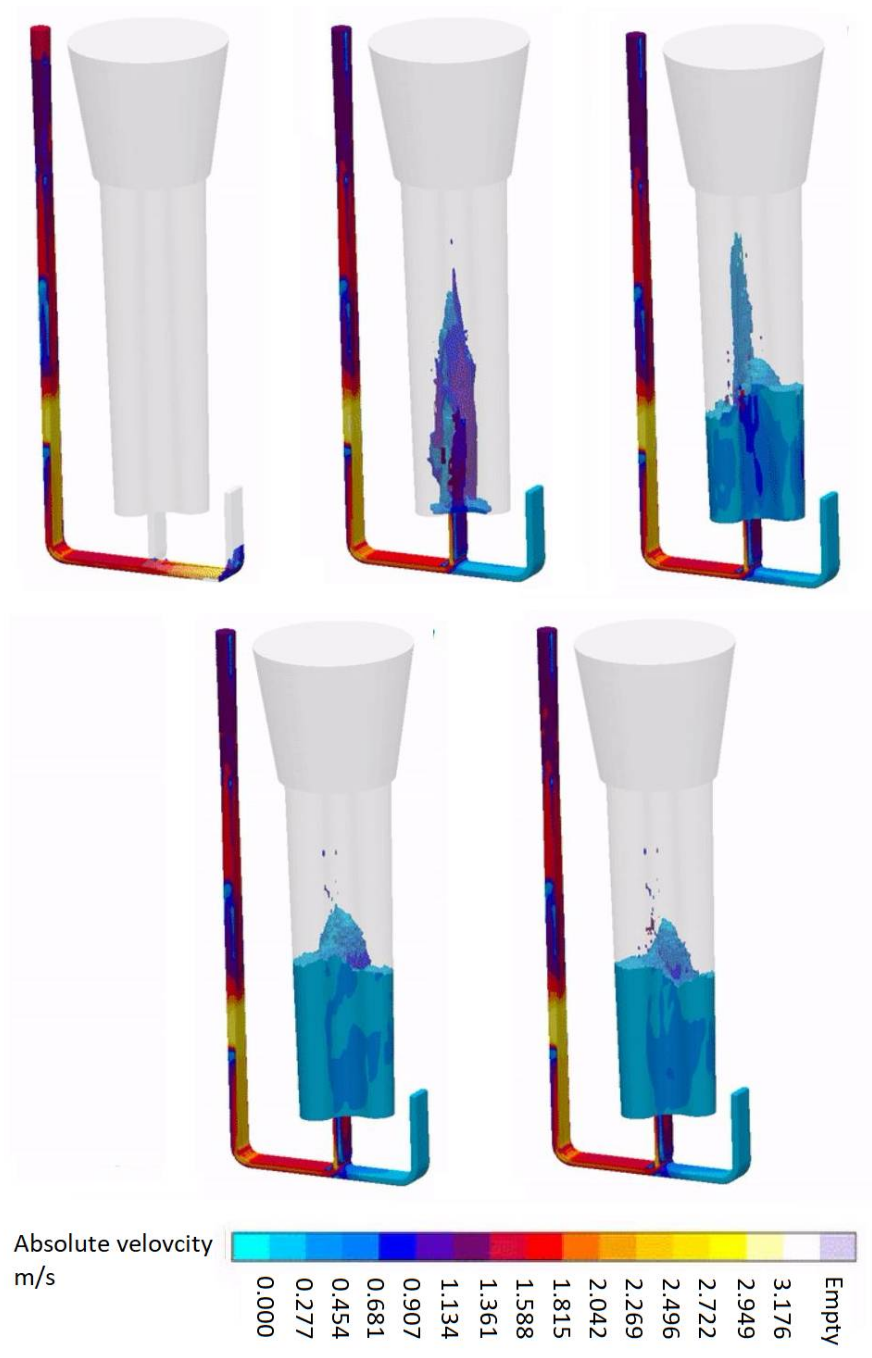
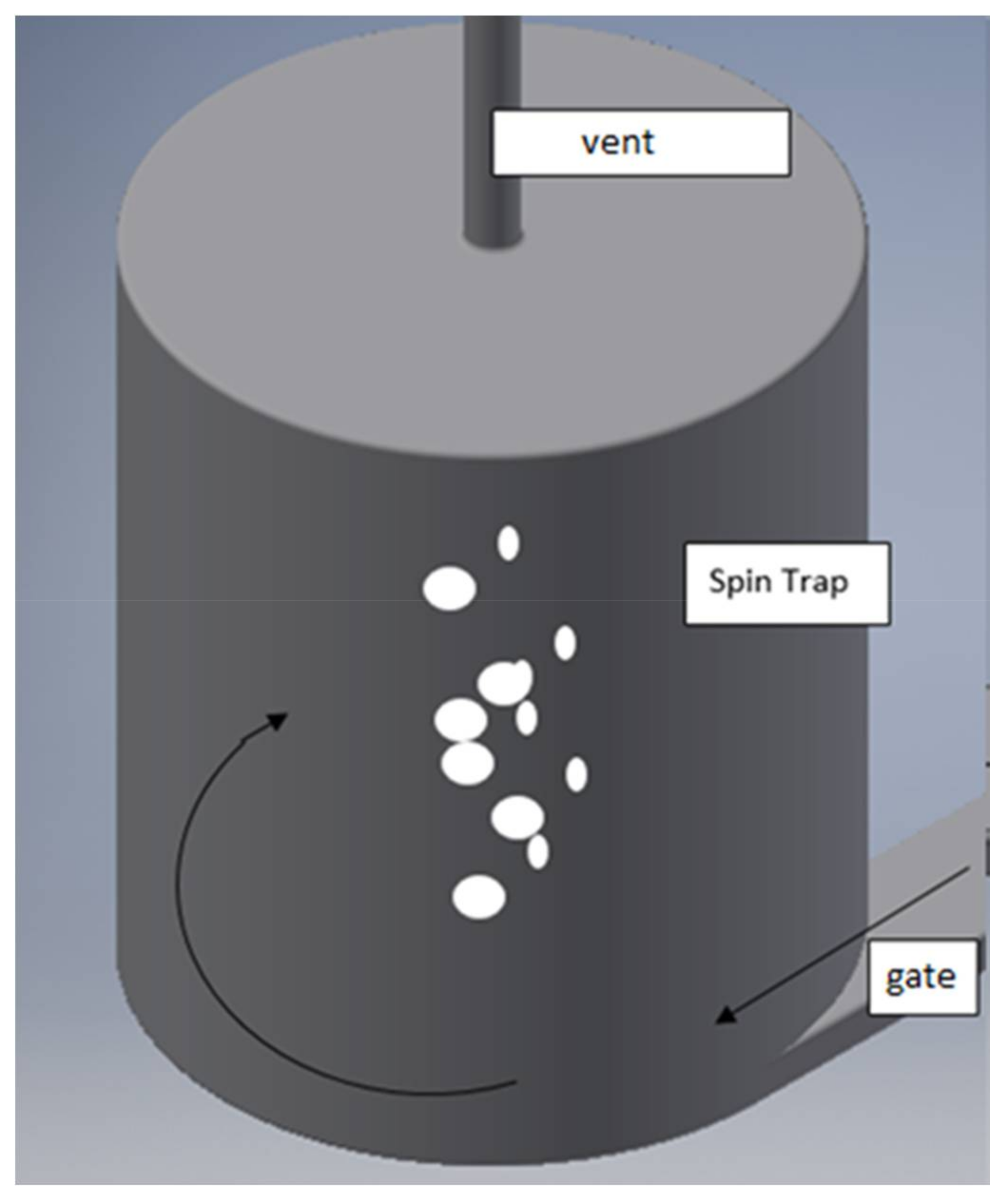
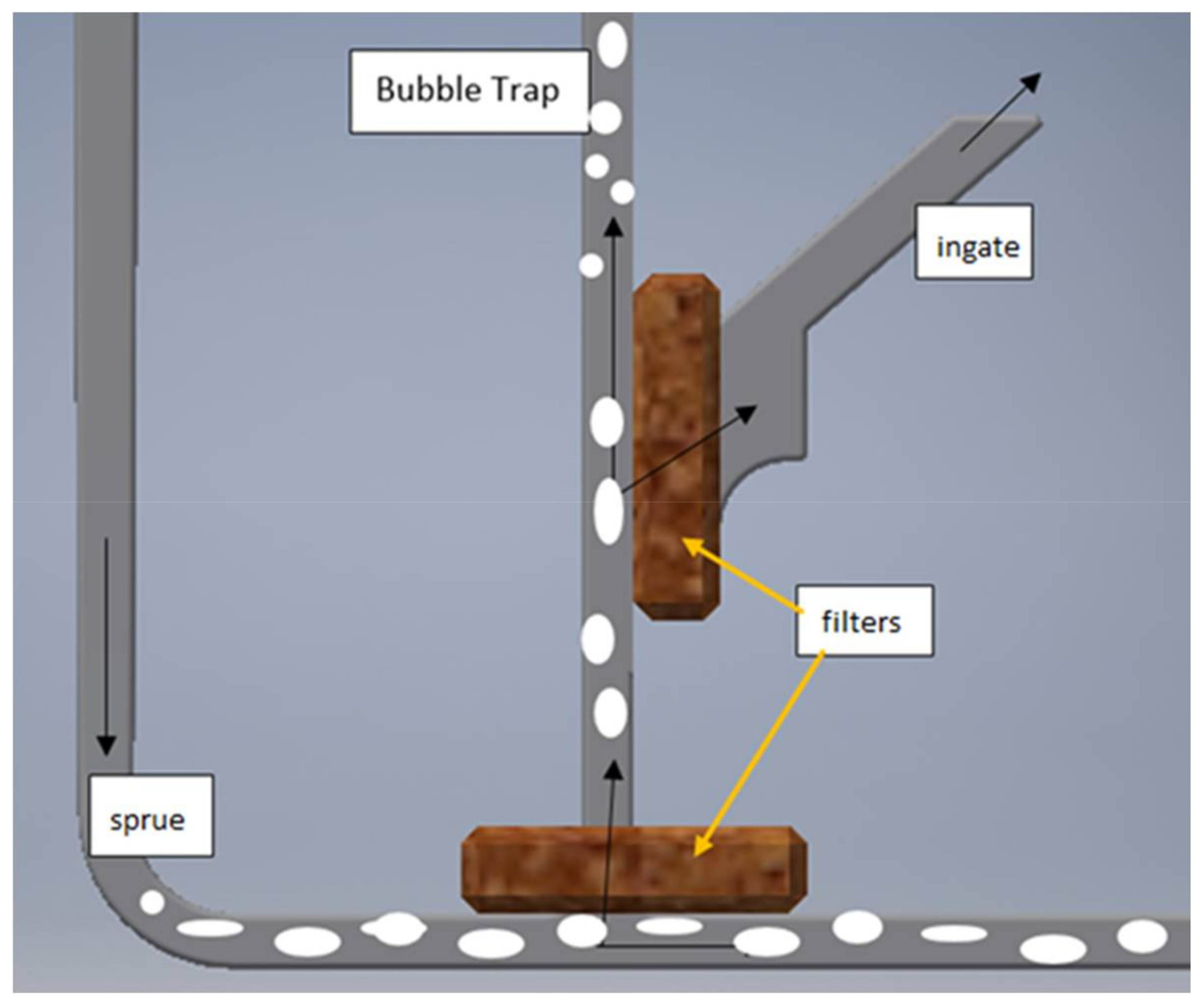
3.5. Spin Trap System

Another gating system modification that was proposed by some researchers is the so-called spin trap system, thus this option was also checked by the authors of this paper. Figure 8 shows the idea of the spin trap and Figure 9 presents the modelling results.
This additional, round cross-section volume is situated at the end of the runner, which is joined at the outer diameter like a typical vortex system. Another version was examined with the spin trap between the down sprue and the mould cavity, but the results were much worse and thus are not presented here. Additionally, there is a vent to evacuate the gases from the mould. The results of such an approach should be the following: flow velocity decrease, liquid alloy degassing, and non-metallic inclusions captured in the spin trap volume.
The results of the last approach seem to be fully acceptable and promising. The velocity of the liquid alloy introducing the mould cavity is ca. 0.4–0.6 m/s, and then during cavity filling it is even lower, ca. 0.3–0.4 m/s. Moreover, the gases and the non-metallic inclusions that are typically located at the front of the metal flow should end up inside the spin trap with the vent. The optimal height-to-diameter ratio of a spin trap will be a topic of further examination. The filter should be placed in the ingate tangentially to the runner in order to prevent any oxide bifilms from entering the mold cavity, as the metal going from the sprue will constantly push them from the surface of the filter into the runner’s extension, where they will be trapped inside a spin trap allowing for increasing the amount of metal being able to flow through a filter without choking it, theoretically, to infinity. The shape and cross section of the ingate can be freely chosen in such a way that it will reduce the speed of metal entering the mold cavity to the desired value.

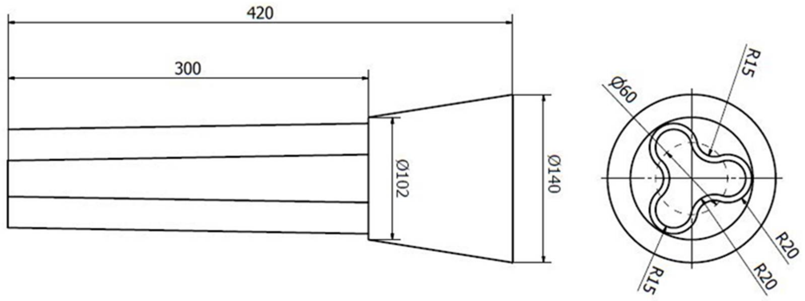
3.6. Trident Gate System

The most complex and engineered is the so-called trident gate, with a combination with a spin trap and an additional bubble trap to take advantage of all the above solutions. Figure 10 presents an approach in which two ceramic filters were perpendicularly located, according to Campbell’s guidelines [33]. The spin trap was added by the authors after very promising results were obtained, as described earlier. Modelling was conducted for the gating system and the results are presented in Figure 11.
This option seems to be the best for a casting poured from the bottom, as it gives the opportunity to decrease the flow velocity to the desired level and the internal quality of the casting should be the best because of the bubble trap, spin trap, and two ceramic filters that were located according to the authors’ best knowledge. This solution is dedicated to aluminum alloys, as they are greatly vulnerable to oxidation defects, although it might be useful in the manufacturing of high quality cast steel castings.

4. Conclusions

After a series of experiments with a step-by-step modified gating system design to achieve a flow velocity that was as close to the “gold standard” of 0.5 m/s as possible and to ensure the capture of gas bubbles and non-metallic (including possible re-oxidation) inclusions, the following conclusions were formulated:
  • The necessity of metal velocity reduction may require a reduction of metallostatic pressure, and a possible solution is using an offset step pouring basin or an intermediate ladle, although it will provide unwanted metal mixing. This option will be checked in the next stage of the experimental plan.
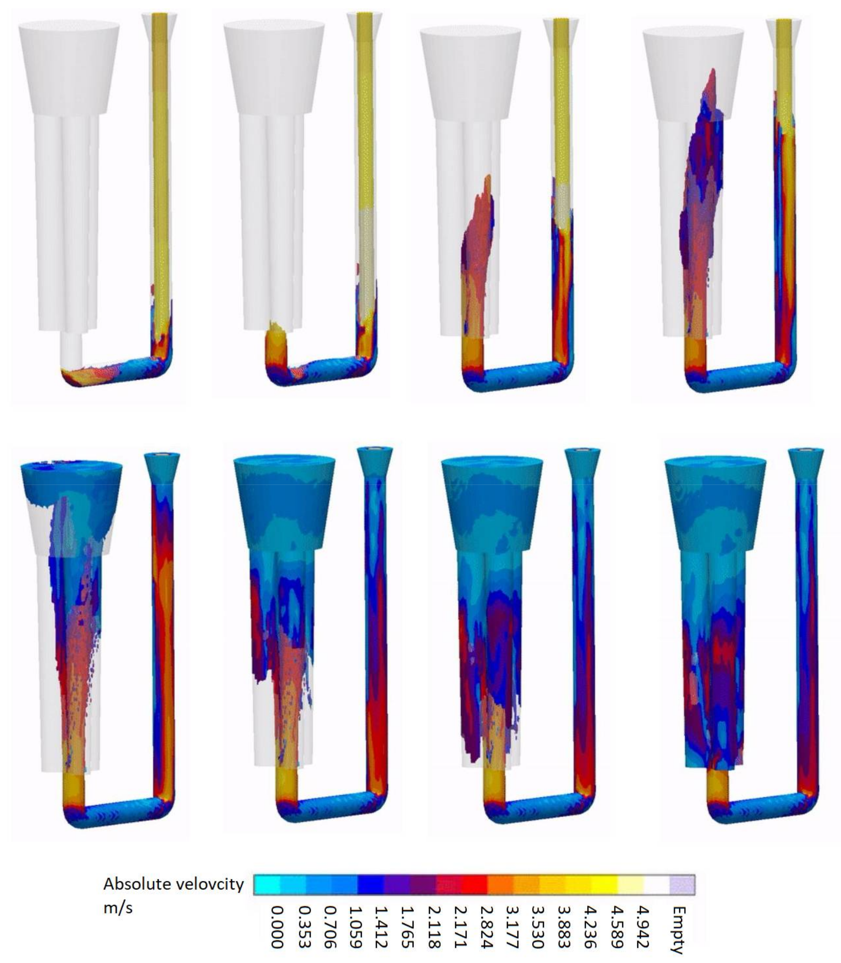
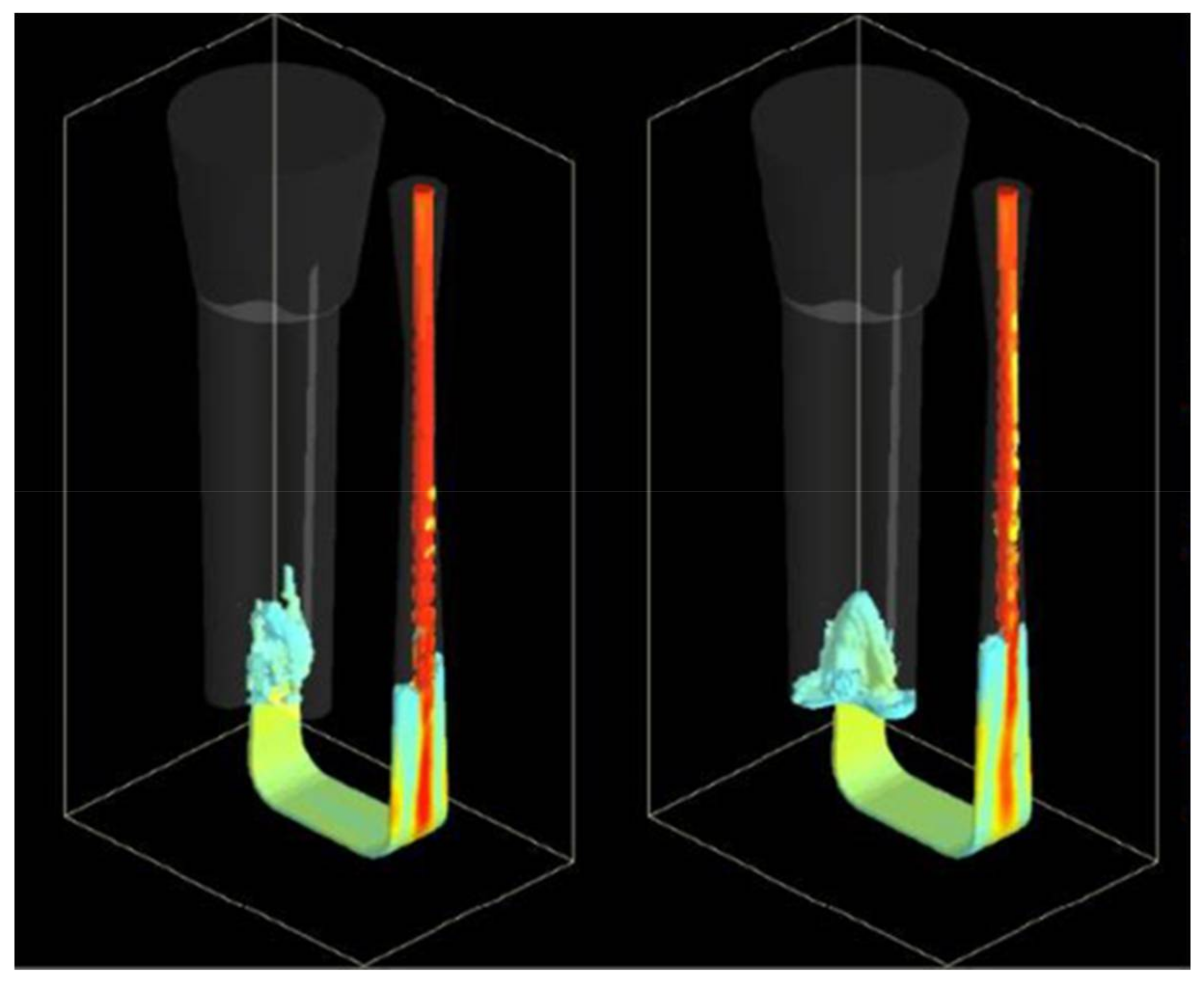
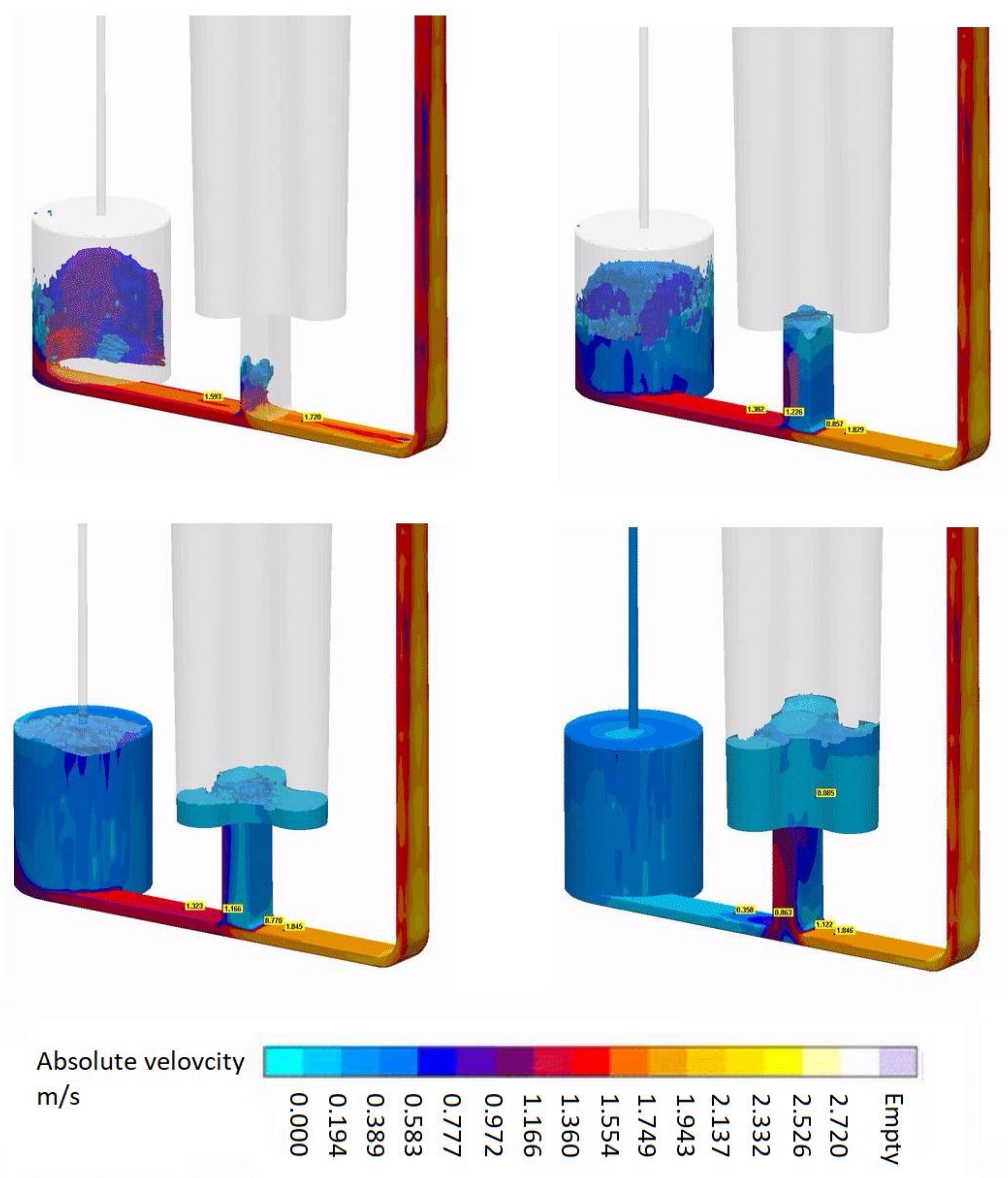
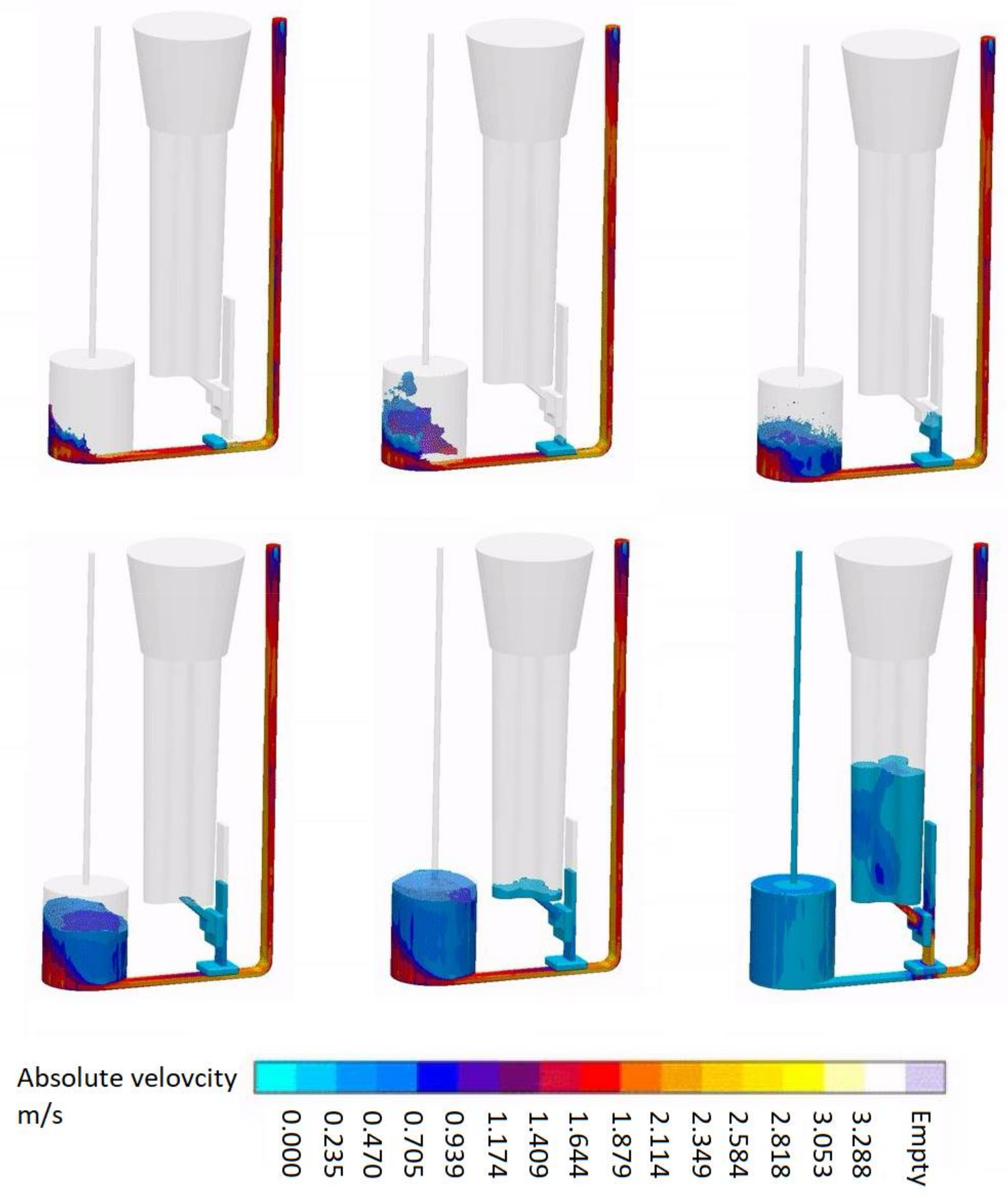
  • The modelling confirms the effectiveness of the gating systems that are presented here as a way of controlling the velocity of the metal entering the mould cavity, although they also allow a much less turbulent flow of metal through the gating system, thus reducing the possibility of bifilm creation that is caused by the re-oxidation process.
  • The most optimal system is the combined system with trident gates, a spin trap, and a bubble trap, and it seems to be an affordable (optimised) approach for heavy, single manufactured castings. The mould is handmade in this case, so no problems relate to shaping an even more complex gating system than that developed for the clover-like sample.
  • Studies are under way that will allow for comparing the gating systems that are presented here in terms of the quality of the obtained castings and the ease of their implementation. Then, after the gating system quality is proven for the clover-like sample, selected commercial castings will be cast based on the results.
  • Application of presented solutions (e.g., spin trap and vortex gates) may decrease the metal yield in comparison to tradition gating systems. However, in the case of responsible casting, especially concerning piece production, yield decrease can be justified with a potential increase of mechanical properties and a reduction of the number of defects.
  • Proper use of the gating system can improve the course of solidification. Thin ingates (with high width and low thickness) have smaller heat module in comparison to round and square gates. This results in their faster solidification after the filling process, and thus the ability to work as a chill.

Author Contributions

Jan Jezierski and Rafał Dojka proposed the research and designed the experiment plan. Rafał Dojka created and conducted the modelling experiments while Jan Jezierski supervised them all. Krzysztof Janerka consulted the results and critically reviewed the paper. Jan Jezierski and Rafał Dojka wrote the paper while Krzysztof Janerka drew all the supplementary sketches and schemes. The article was proofread by the professional.

Conflicts of Interest

The authors declare no conflict of interest.

References

  1. Soiński, M.; Kordas, P.; Skurka, K. Trends in the production of castings in the world and in Poland in the XXI century. Arch. Foundry Eng. 2016, 16, 5–10. [Google Scholar] [CrossRef]
  2. Danko, J.; Holtzer, M. The state of art and foresight of world’s casting production. Metalurgija 2006, 45, 333–340. [Google Scholar]
  3. Holtzer, M.; Dańko, R.; Żymankowska-Kumon, S. The state of art and foresight of world’s casting production. Metalurgija 2014, 53, 697–700. [Google Scholar]
  4. Li, D.; Sun, M.; Wang, P.; Kang, X.; Fu, P.; Li, Y. In process modelings and simulations of heavy castings and forgings. In Proceedings of the 11th International Conference on Numerical Methods in Industrial Forming Processes (NUMIFORM), Shenyang, China, 6–10 July 2013; pp. 81–94. [Google Scholar]
  5. Liu, B.C.; Kang, J.W.; Huang, T.Y. Stress analysis and deformation prediction of a heavy hydraulic turbine blade casting during casting and heat treatment. Mater. Sci. Technol. 2012, 28, 808–811. [Google Scholar] [CrossRef]
  6. Foglio, E.; Gelfi, M.; Pola, A.; Goffelli, S.; Lusuardi, D. Fatigue characterization and optimization of the production process of heavy section ductile iron castings. Int. J. Metalcast. 2017, 11, 33–43. [Google Scholar] [CrossRef]
  7. Kang, J.; Huang, T.; Liu, B. Review of production status of heavy steel castings and key technologies for their manufacture in china. China Foundry 2008, 5, 1–6. [Google Scholar]
  8. Kang, J.; Wang, T.; Huang, T.; Liu, B. Deformation prediction of a heavy hydro turbine blade during the casting process with consideration of martensitic transformation. Metall. Mater. Trans. A 2013, 44A, 5343–5353. [Google Scholar] [CrossRef]
  9. Olejnik, E.; Szymański, L.; Kurtyka, P.; Tokarski, T.; Grabowska, B.; Czapla, P. Hardness and wear resistance of TiC-Fe-Cr locally reinforcement produced in cast steel. Arch. Foundry Eng. 2016, 16, 89–94. [Google Scholar] [CrossRef]
  10. Stradomski, G. The cracking mechanism of ferritic-austenitic cast steel. Arch. Foundry Eng. 2016, 16, 153–156. [Google Scholar] [CrossRef]
  11. Camek, L.; Lichy, P.; Kroupova, I.; Duda, J.; Beno, J.; Korbas, M.; Radkovsky, F.; Bliznyukov, S. Effect of cast steel production metallurgy on the emergence of casting defects. Metalurgija 2016, 55, 701–704. [Google Scholar]
  12. Burdzik, R.; Konieczny, L.; Stanik, Z.; Folega, P.; Smalcerz, A.; Lisiecki, A. Analysis of impact of chosen parameters on the wear of camshaft. Arch. Metall. Mater. 2014, 59, 957–963. [Google Scholar] [CrossRef]
  13. Dulska, A.; Baron, C.; Szajnar, J. The analysis of the effects of heat and mass movement during alloy layer forming process on steel cast. In Proceedings of the 25th Anniversary International Conference on Metallurgy and Materials METAL, Brno, Czech Republic, 25–27 May 2016; pp. 110–115. [Google Scholar]
  14. Szajnar, J.; Dulska, A.; Wrobel, T.; Baron, C. Description of alloy layer formation on a cast steel substrate. Arch. Metall. Mater. 2015, 60, 2367–2372. [Google Scholar] [CrossRef]
  15. Studnicki, A.; Jezierski, J. Stereological parameters of carbides in modified wear resistant Fe-C-Cr alloys. In Proceedings of the 21st International Conference on Metallurgy and Materials METAL, Brno, Czech Republic, 23–25 May 2012; pp. 795–802. [Google Scholar]
  16. Janerka, K.; Jezierski, J.; Bartocha, D.; Szajnar, J. Analysis of ductile iron production on steel scrap base. Int. J. Cast Met. Res. 2014, 27, 230–234. [Google Scholar] [CrossRef]
  17. Stawarz, M.; Kajzer, W.; Kajzer, A.; Dojka, M. Physicochemical properties of silicon cast iron. Arch. Foundry Eng. 2017, 17, 101–106. [Google Scholar] [CrossRef]
  18. Stawarz, M. SiMo ductile iron crystallization process. Arch. Foundry Eng. 2017, 17, 147–152. [Google Scholar] [CrossRef]
  19. Fragassa, C.; Radovic, N.; Pavlovic, A.; Minak, G. Comparison of mechanical properties in compacted and spheroidal graphite irons. Tribol. Ind. 2016, 38, 49–59. [Google Scholar]
  20. Fragassa, C.; Minak, G.; Pavlovic, A. Tribological aspects of cast iron investigated via fracture toughness. Tribol. Ind. 2016, 38, 1–10. [Google Scholar]
  21. Fragassa, C.; Zigulic, R.; Pavlovic, A. Push-pull fatigue test on ductile and vermicular cast irons. Eng. Rev. 2016, 36, 269–280. [Google Scholar]
  22. Gumienny, G.; Kacprzyk, B.; Gawronski, J. Effect of copper on the crystallization process, microstructure and selected properties of CGI. Arch. Foundry Eng. 2017, 17, 51–56. [Google Scholar] [CrossRef]
  23. Guzik, E.; Sokolnicki, M.; Nowak, A. Effect of heat treatment parameters on the toughness of unalloyed ausferritic ductile iron. Arch. Foundry Eng. 2016, 16, 79–84. [Google Scholar] [CrossRef]
  24. David, P.; Massone, J.; Boeri, R.; Sikora, J. Gating system design to cast thin wall ductile iron plates. Int. J. Cast Met. Res. 2006, 19, 98–109. [Google Scholar] [CrossRef]
  25. Pei, Q.; Liu, B.; Yu, X.; Guo, H.; Chen, G. A computer-aided-design system for optimizing risering and gating design of steel castings. In Proceedings of the International Conference on CAD of Machinery, Beijing, China, 16–20 September 1991; pp. 256–261. [Google Scholar]
  26. Smith, R.W.; DeMonte, A.; Mackay, W.B.F. Development of high-manganese steels for heavy duty cast-to-shape applications. J. Mater. Process. Technol. 2004, 153, 589–595. [Google Scholar] [CrossRef]
  27. Yang, D.; Li, S.; He, F.; Sung, W.; Kao, J.; Chen, R. Twin gating system design for typical thin wall stainless steel castings based on fast pouring mechanism. Front. Mech. Eng. Mater. Eng. II 2014, 457–458, 1657–1660. [Google Scholar] [CrossRef]
  28. Pawliczek, A.; Vladik, V. Impact of electric power prices on total costs of foundry casting production with the side effect on global competitiveness. In Proceedings of the 23rd International Conference on Metallurgy and Materials METAL, Brno, Czech Republic, 21–23 May 2014; pp. 1558–1563. [Google Scholar]
  29. Ducic, N.; Slavkovic, R.; Milicevic, I.; Cojbasic, Z.; Manasijevic, S.; Radisa, R. Optimization of the gating system for sand casting using genetic algorithm. Int. J. Metalcast. 2017, 11, 255–265. [Google Scholar] [CrossRef]
  30. Fourie, J.; Lelito, J.; Zak, P.; Krajewski, P.; Wolczynski, W. Numerical optimization of the gating system for an inlet valve casting made of titanium alloy. Arch. Metall. Mater. 2015, 60, 2437–2446. [Google Scholar] [CrossRef]
  31. Hawranek, R.; Lelito, J.; Suchy, J.; Zak, P. The simulation of a liquid cast iron flow through the gating system with filter. Arch. Metall. Mater. 2009, 54, 351–358. [Google Scholar]
  32. Huang, P.; Lin, C. Computer-aided modeling and experimental verification of optimal gating system design for investment casting of precision rotor. Int. J. Adv. Manuf. Technol. 2015, 79, 997–1006. [Google Scholar] [CrossRef]
  33. Modaresi, A.; Safikhani, A.; Noohi, A.; Hamidnezhad, N.; Maki, S. Gating system design and simulation of gray iron casting to eliminate oxide layers caused by turbulence. Int. J. Metalcast. 2017, 11, 328–339. [Google Scholar] [CrossRef]
  34. Campbell, J. “Stop pouring, start casting”. Int. J. Metalcast. 2012, 6, 7–18. [Google Scholar] [CrossRef]
  35. Campbell, J. Cavitation in liquid and solid metals: Role of bifilms. Mater. Sci. Technol. 2015, 31, 565–572. [Google Scholar] [CrossRef]
  36. Campbell, J. Sixty years of casting research. Metall. Mater. Trans. A 2015, 46A, 4848–4853. [Google Scholar] [CrossRef]
  37. Campbell, J. Crack populations in metals. AIMS Mater. Sci. 2016, 3, 1436–1442. [Google Scholar] [CrossRef]
  38. Campbell, J. Melting, remelting, and casting for clean steel. Steel Res. Int. 2017, 88, 1–13. [Google Scholar] [CrossRef]
  39. Campbell, J. The consolidation of metals: The origin of bifilms. J. Mater. Sci. 2016, 51, 96–106. [Google Scholar] [CrossRef]
  40. Hsu, F.; Jolly, M.; Campbell, J. A multiple-gate runner system for gravity casting. J. Mater. Process. Technol. 2009, 209, 5736–5750. [Google Scholar] [CrossRef] [Green Version]
  41. Hsu, F.; Jolly, M.; Campbell, J. Vortex-gate design for gravity casting. Int. J. Cast Met. Res. 2006, 19, 38–44. [Google Scholar] [CrossRef]
  42. Jezierski, J.; Dojka, R.; Kubiak, K.; Zurek, W. Experimental approach for optimization of gating system in castings. In Proceedings of the 25th Anniversary International Conference on Metallurgy and Materials METAL, Brno, Czech Republic, 25–27 May 2016; pp. 104–109. [Google Scholar]
Figure 1. Clover-like sample according to Polish norm PN-H-04309:1976.
Metals 08 00266 g001
Figure 2. Reference geometry of the gating system pouring process; average filling time 2 s.
Metals 08 00266 g002
Figure 3. Various modifications of the gating system (downsprue) geometry.
Metals 08 00266 g003
Figure 4. Improper downsprue tapering (NovaFlow & Solid).
Metals 08 00266 g004
Figure 5. Prolonged runner system pouring process; filling time 10 s.
Metals 08 00266 g005
Figure 6. Vortex gate system idea.
Metals 08 00266 g006
Figure 7. Vortex gate system pouring process; filling time 10 s.
Metals 08 00266 g007
Figure 8. Spin trap idea.
Metals 08 00266 g008
Figure 9. Spin trap gating system; filling time 10 s.
Metals 08 00266 g009
Figure 10. Trident gate system with filters.
Metals 08 00266 g010
Figure 11. Combined gating system design; filling time 10 s.
Metals 08 00266 g011

