Article

Effect of Cold Rolling on the Mechanical Properties and Formability of FSWed Sheets in AA5754-H114

by
Giuseppe Casalino
1,
Mohamad El Mehtedi
2,
Archimede Forcellese
2 and
Michela Simoncini
3,*
1
Dipartimento di Meccanica Management Matematica (DMMM), Politecnico di Bari, Viale Japigia 182, 70126 Bari, Italy
2
Dipartimento di Ingegneria Industriale e Scienze Matematiche (DIISM), Università Politecnica delle Marche, Via Brecce Bianche, 60100 Ancona, Italy
3
Università degli Studi eCampus, Via Isimabrdi 10, 22060 Novedrate, Italy
*
Author to whom correspondence should be addressed.
Metals 2018, 8(4), 223; https://doi.org/10.3390/met8040223
Submission received: 27 February 2018 / Revised: 23 March 2018 / Accepted: 25 March 2018 / Published: 28 March 2018

Abstract

:
The effect of cold rolling, performed after friction stir welding (FSW), on the mechanical properties and formability of joints in AA5754-H114 aluminium alloy was investigated. Friction stir welding was carried out on 2.5 mm thick sheets with constant values of rotational and welding speeds of 1200 rpm and 100 mm/min, respectively. Then, FSWed workpieces were cold rolled, with the rolling direction perpendicular to the welding line, in order to obtain height reductions ranging from 0.1 to 0.5 mm. Cold rolling with the same height reductions was also carried out on the base material in the as-received condition. The mechanical properties and formability of both friction stir welded joints and base material, before and after cold rolling, were evaluated by means of the uniaxial tensile and hemispherical punch tests. The nominal stress vs. nominal strain and punch force vs. punch stroke curves were analysed in detail. Finally, the scanning electron microscope fractography was used to evaluate the fractured surface of tensile samples.

1. Introduction

Friction Stir Welding (FSW) is a solid state process developed for the obtaining of joints with higher mechanical properties and formability than those provided by fusion welding technologies [1,2,3,4,5,6,7,8]. Manufacturing of multi-sheet structures obtained by assembling two or more blanks, also using different materials and/or thicknesses, is the industrial field able to obtain the greatest benefits by FSW. Another area of interest is represented by the joining of un-weldable alloys through fusion technologies [1,9,10,11,12,13].
In the FSW a tool, with a shoulder and a profiled pin, is used to weld sheet workpieces without reaching the melting temperature of workpiece material. Frictional heat, generated between the rotating tool and blanks, leads to the formation of a softened and dynamically recrystallised zone, i.e., nugget, which approximately corresponds to the location of the pin tool during welding. As the rotating tool is moved along the welding line, it mechanically intermixes the workpieces from the advancing to the retreating side. Therefore, the FSW process exploits the frictional heat generated between tool and workpieces, along with that generated by the stirring action of the tool and the adiabatic heat within the material, to promote a strong plastic deformation of the workpieces and their complex mixing across the weld [1,14,15,16,17,18,19].
Notwithstanding the several advantages provided, FSW is characterised by some drawbacks which can reduce its application if joints with high strength are required. An important limitation is the forging action applied by the tool shoulder, necessary to generate frictional heating, which causes a thickness decrease in an area whose width and length are equal to the shoulder diameter and tool travel along the welding line, respectively [20]. Such thinning produces the reduction of both mechanical properties and formability of joints, with an effect that becomes ever more marked as the initial sheet thickness decreases. Forging also leads to the worsening of aesthetic appearance of the welded workpieces.
A further aspect referred to as a limitation in friction stir welding is related to the small geometric clearance between the bottom side of the pin and backing plate which is necessary to avoid their direct contact during the welding process [21,22]. Depending on the tool geometry and process parameters, it can cause the formation of a small discontinuity (kissing bond) located at the root of the weld, which reduces the effective cross-sectional area of weld. Furthermore, the discontinuity acts as a notch involving a local increase in the intensity of stress field and, consequently, a quicker crack propagation as joints are subjected to post-welding forming processes.
An approach developed by the authors to remove the forging effect by ensuring a constant sheet thickness was to subject the friction stir welded (FSWed) workpieces to cold rolling (CR) [23]. Rolling could be also useful to reduce the depth of the discontinuity at the bottom surface of weld. In order to obtain such results, the height reduction of cold rolling should be accurately chosen by additionally taking into account the strain hardening effect due to cold deformation on the mechanical properties and formability of the welded blank.
In this framework, the present work aims to investigate the influence of the cold rolling process on the mechanical properties and formability of friction stir welded sheets in AA5754-H114 aluminium alloy. FSW experiments were carried out on sheet workpieces with a thickness of 2.5 mm. Then, the welds were cold rolled, with the rolling direction perpendicular to the welding line, by imparting one or more passes, each of them with a height reduction of 0.1 mm. The effect of FSW on the final properties of sheet workpieces was studied by performing cold rolling on the base material in the as-received condition. The mechanical properties and formability of FSWed joints and base material, before and after cold rolling, were evaluated by means of uniaxial tensile and hemispherical punch tests. The tensile specimens were also subjected to micro-fractography analyses performed by means of scanning electron microscopy.

2. Material and Experimental Procedures

2.1. Material

The material used was AA5754 aluminium alloy, supplied in form of 2.5 mm thick sheets, in the H-114 temper state. The chemical composition of the alloy is shown in Table 1. This alloy is used in the aeronautic and automotive industries for structural panels, owing to its excellent corrosion resistance properties, especially to seawater and industrially polluted atmospheres.

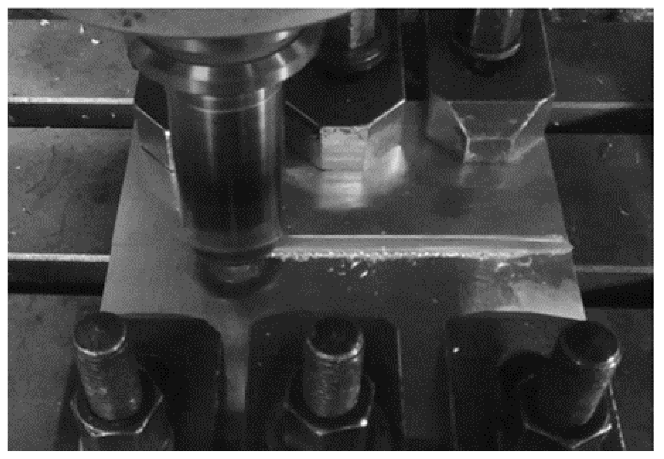
2.2. Friction Stir Welding

Butt joints were obtained by FSW experiments carried out, using the computer numerical control machining center COMEC M50, on sheet workpieces with a length, width and thickness equal to 185 mm, 80 mm and 2.5 mm, respectively (Figure 1). Table 2 specifies the geometric features of pin tool, and Table 3 shows the welding parameters defined in a previous study in which the weldability of AA5754-H114 alloy was investigated [24]. Experiments were carried out by keeping constant the values of rotational speed, welding speed and tool sinking during the welding stage; the welding line was perpendicular to the rolling direction of sheets in the as-received condition.

2.3. Cold Rolling

The FSWed workpieces were cold rolled after joining (FSWed+CRed condition). The CR process was performed on strips, 90 mm in width and 170 mm in length, obtained by water jet cutting the FSWed joints so that the length side of the strip was perpendicular to the welding line. The strips were obtained in the central zone of the weld in which the FSW process can be considered stationary. The height reduction (Δh) of each rolling pass was equal to 0.1 mm. Strips with an uniform thickness equal to 2.4, 2.3, 2.2, 2.1 and 2.0 mm were obtained with a number of passes rising from 1 to 5, respectively.
Cold rolling was also carried out on strips, 90 mm in width, 170 mm in length and 2.5 mm in thickness, cut from the base material (BM) in order to obtain the same thicknesses of the FSWed+CRed strips. The length side of BM+CRed strips was parallel to the rolling direction of AA5754 sheet in the as-received condition.

2.4. Uniaxial Tensile Tests

The effect of cold rolling on the mechanical properties of both FSWed and BM blanks was investigated by carrying out room temperature uniaxial tensile tests performed, according to ASTM E8/E8M and BS EN 895, on the servo-hydraulic universal testing machine MTS 810. The tests were carried out with a constant traverse speed equal to 0.1 mm/s. Both FSWed+CRed and BM+CRed strips, after cold rolling with Δh values ranging between 0.1 and 0.5 mm, were machined to obtain tensile samples with loading direction parallel to the cold rolling one. Tensile tests were also carried out on the FSWed workpieces and BM before cold rolling on samples with the loading direction perpendicular to welding line and parallel to the rolling direction of AA5754 sheets in the as-received condition, respectively. At least three repetitions for each condition were undertaken. Nominal stress (S) and nominal strain (e) were acquired during testing. The yield strength (YS), ultimate tensile strength (UTS) and ultimate elongation in percentage (UE) were derived from the S-e curves. Finally, the true stresses and true strains in the region of uniform plastic deformation were calculated and processed to evaluate the work hardening behaviour in both FSWed+CRed and BM+CRed conditions.

2.5. Formability Tests

The influence of cold rolling on the room temperature formability of both welded workpieces and base material was studied using the hemispherical punch test carried out on the servo-hydraulic universal testing machine MTS 810. The punch speed was kept constant and equal to 0.1 mm/s. Both FSWed and BM strips, after cold rolling with Δh values varying from 0.1 to 0.5 mm, were machined to obtain 90 mm × 90 mm square samples. Hemispherical punch tests were also carried out on the FSWed and BM samples before cold rolling.
The FSWed and FSWed+CRed samples were placed on the die with the side that was in touch with shoulder during welding opposed to the hemispherical punch surface.
The punch load (F) and punch stroke (Δs) were recorded during testing. Formability was measured by the limiting dome height (LDH) defined by the punch stroke at the peak of the load vs. stroke curve. For each process condition, experimental trials were repeated at least three times.

2.6. Microstructural Analysis

The scanning electron microscope (SEM) Philips XL20 (Philips, Amsterdam, The Netherlands), in backscattered electron mode, was used to obtain high magnification images of fractured surfaces. To this end, the tensile tested fracture surfaces were cleaned by means of ultrasonic cleaner with acetone for 10 min; then, they were analysed by SEM in order to accurately identify the fracture mechanisms as a function of the height reduction imposed by cold rolling process on both FSWed and BM workpieces.

3. Experimental Results

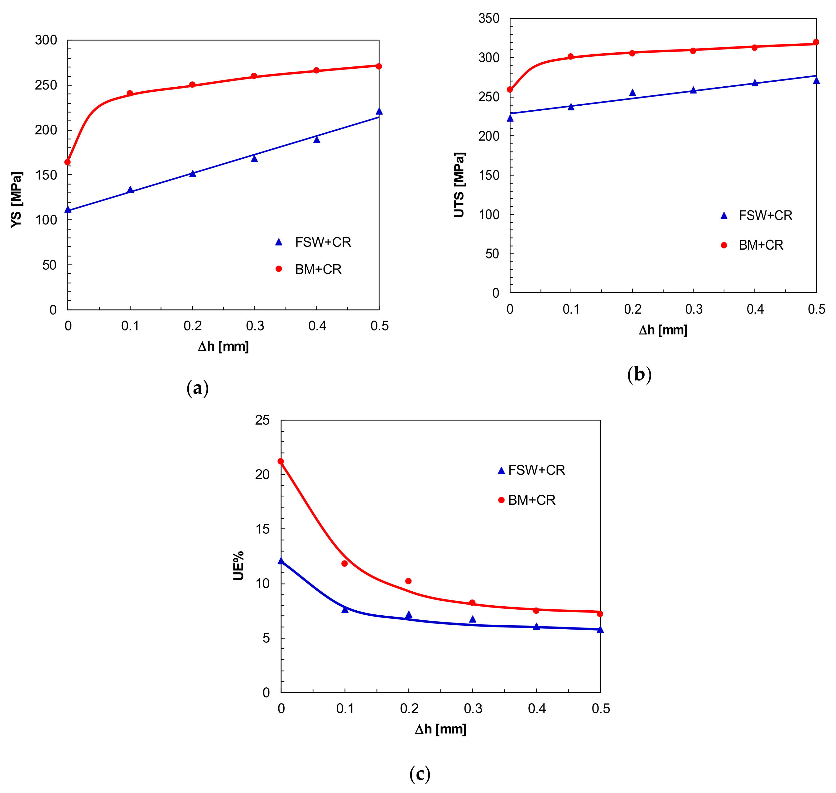
3.1. Effect of Cold Rolling on the Mechanical Properties of FSWed Workpieces

The nominal stress vs. nominal strain curves of AA5754-H114 aluminium alloy in the FSWed+CRed condition are shown in Figure 2a in which the S-e plot of FSWed workpiece before cold rolling is also reported for reference. After reaching the peak value, the flow stress does not exhibit any appreciable decrease with increasing strain before failure, i.e., the tensile sample does not show a significant necking. Fracture takes place along the welding line and sheet thinning is localised in the fractured zone (Figure 2b). Such behaviour becomes ever more evident as the number of cold rolling passes increases. Furthermore, for a given strain, the S value obtained by deforming FSWed+CRed samples is higher than that given by FSWed one; such discrepancy monotonically increases with Δh. Finally, the FSWed+CRed samples exhibit values of the ultimate elongation lower than that of the FSWed one; such difference grows with height reduction applied by cold rolling.
The plastic flow behaviour of the base material is characterised by a post-necking deformation before failure (Figure 2c) much more pronounced than in the FSWed samples (Figure 2a). The sheet thinning distributed throughout the gauge length and the post-necking deformation decreases as the number of cold rolling passes increases (Figure 2d). Furthermore, according to the behaviour exhibited by tensile samples in the FSWed+CRed condition, the S value obtained by deforming BM+CRed samples is significantly higher than that provided by BM with a discrepancy growing with height reduction. When considering ductility, the UEBM+CRed values are lower than UEBM with a gap rising with Δh.
Figure 3 shows the comparison between mechanical behaviour exhibited by AA5754-H114 alloy in the FSWed+CRed and BM+CRed conditions. Irrespective of height reduction, the yield strength and ultimate tensile strength in the FSWed+CRed condition are lower than those of the BM+CRed (Figure 3a,b); such results are consistent with those exhibited by the FSWed and BM samples before cold rolling (Δh = 0). The growth rates of YS and UTS with Δh are almost independent to the number of rolling passes. By considering the base material, both YS and UTS strongly increases after the first rolling pass (Δh = 0.1 mm); then, their growth rates decrease and kept to an almost constant value. As ductility is considered (Figure 3c), irrespective of Δh value, the ultimate elongation in the FSWed+CRed condition is lower than that of the BM+CRed. This is consistent with the behaviour exhibited by FSWed and BM samples before cold rolling. However, while the discrepancy between UEBM and UEFSW is equal to 42.9%, the difference between the UEBM+CRed and UEFSW+CRed decreases from 35.8% with Δh = 0.1 mm to 19.1% with Δh = 0.5 mm. It means that the cold rolling process leads to a much less pronounced decrease of ductility in the FSWed workpieces than in the BM.
Figure 4 shows the SEM images of the fractured surfaces exhibited by the FSWed and FSWed+CRed samples. Irrespective of the height reduction imposed by cold rolling, they reveal a ductile behaviour with microvoid coalescence (Figure 4a,c,e). In fact, tensile loading results in equiaxed dimples that coalesce perpendicular to the loading direction. However, cracks propagating along the direction of welding motion can be also seen (Figure 4b,d,f); furthermore, the extent of cracks tends to increase with the height reduction. The SEM images of the BM and BM+CRed samples show a ductile fracture surface morphology which is not influenced by height reduction (Figure 5) indicating that, in the experimental conditions of the present work, cold rolling does not significantly affect the fracture mechanisms. Finally, the cracks observed in the welded samples are not present in the BM both before and after cold rolling.

3.2. Effect of Cold Rolling on the Formability of FSWed Workpieces
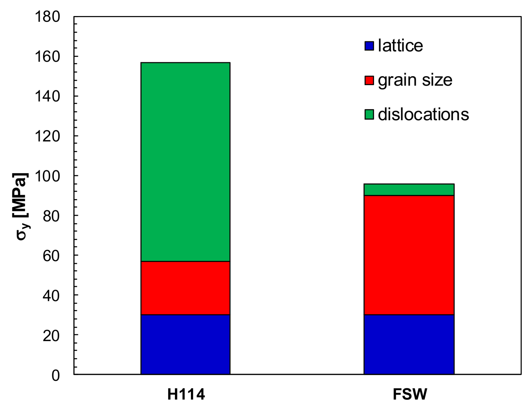
The results of a hemispherical punch test on AA5754-H114 alloy in the FSWed+CRed condition, expressed in terms of punch load vs. stroke curve, are shown in Figure 6a in which they are compared with the F-Δs curve of FSWed sample. A reduction in the peak value of the F-Δs curve, i.e., in the limiting dome height, with increasing the number of cold rolling passes clearly appears (Figure 7a). Such decrease takes place at a lower rate until Δh < 0.3 mm and at a higher rate as Δh ≥ 0.3 mm. Furthermore, the peak value of the punch load decreases with Δh due to the reduction of both the punch stroke until failure and sheet thickness. In addition, the BM+CRed samples exhibit a behaviour characterised by a decrease in the LDH with increasing Δh (Figure 6b and Figure 7b). However, the strong reduction in the limiting dome height observed for high Δh values in the FSWed+CRed condition does not occur.
Figure 8a shows the comparison between FSWed+CRed and BM+CRed samples in terms of punch stroke at the peak value of the load vs. stroke curve. Consistent with the behaviour exhibited by the FSWed and BM samples, before cold rolling, the LDH values in the FSWed+CRed condition are slightly lower than those of BM+CRed until a height reduction equal to 0.2 mm is reached. Then, the discrepancy strongly increases and, as Δh = 0.5 mm, the LHDFSWed+CRed is about half of LHDBM+CRed.
In both FSWed and in the FSWed+CRed sample with Δh = 0.2 mm, ductile fracture occurs in the welded zone (Figure 8b,c), as also shown by Liu et al. in [25]. Crack start developing from the bottom surface, propagate in the direction of the maximum equivalent plastic strain, through the thickness and follows a circumferential path. The resulting fracture surface exhibits a dimpled structure with microvoids. As far as the FSWed+CRed sample with Δh = 0.5 mm is concerned (Figure 8d), localised thinning is observed in the weld seam resulting in elongation along the welding line. The BM+CRed condition, irrespective of height reduction, exhibits ductile fracture with a crack following a circumferential path (Figure 8e–g).

4. Discussion

The mechanical behaviour obtained by analysing the results of uniaxial tensile tests carried out on FSWed+CRed AA5754 alloy is affected to a greater extent by the strain hardening caused by cold rolling. To this end, Figure 9a shows the strain hardening exponent (n) in the FSWed+CRed condition as a function of Δh. The decrease in n value with increasing Δh leads to the reduction of strain at the onset of necking and, due to the very low post-necking deformation, of the ultimate elongation with increasing Δh shown in Figure 3c. However, since the strain hardening exponent in the FSWed+CRed condition is higher than that of the BM+CRed, with a discrepancy that is almost independent of height reduction, it is expected that UEFSWed+CRed would be higher than UEBM+CRed. The reverse behaviour observed in Figure 3c, with the ductility of the FSWed+CRed tensile samples being lower than those of the BM+CRed samples, can be attributed, besides the higher post-necking deformation in the BM+CRed condition, to the cracks occurring in welded and cold rolled samples (Figure 4c,d). In fact, by reducing the structural integrity of the material, these factors lead to a decrease in the load carrying capacity of blank.
Figure 9b shows the relationship between the ultimate elongation and strain hardening exponent for both FSWed+CRed and BM+CRed conditions investigated. A non-linear direct correlation occurs with an increase in the UE value with n, confirming that the ductility is strongly dependent on the strain hardening exponent. Furthermore, it is seen that the UE value grows with n with an almost linear trend as Δh ≠ 0 and exhibits a marked increase as Δh = 0. Finally, the discrepancy between UEBM+CRed and UEFSWed+CRed is low for low n values, i.e., for high Δh values, and tends to increase with strain hardening exponent reaching the highest value as the FWSed and BM conditions are compared.
The different mechanical behavior, in terms of strength and strain hardening response, can be rationalised by taking into account the different microstructural phenomena occurring during deformation of the tensile samples in both FSWed+CRed and BM+CRed conditions. A simple estimate of the stress at the early beginning of plastic straining can be obtained by the equation:
σ   =   σ i   +   σ g   +   σ s o l   +   σ ρ   =   σ i   +   σ s o l   +   K d   +   α · m · G · b · ρ
where σi is the strength of the annealed crystal, σsol is the solid solution strengthening term (mainly due to Mg), σg is the strengthening due to grain refinement, K is a constant, d is the grain size, α is a constant (=0.3), m is the Taylor factor (= 3.06), G is the shear modulus, b is the Burgers vector (=2.54 × 10⁻¹⁰ m), and ρ is the dislocation density [26]. At yielding, for undeformed alloys containing 2.5–3% Mg, the true yield stress (σy) can be calculated as:
σ y   =   σ i + σ g + σ s o l + σ ρ   =   ( σ i + σ s o l + α · m · G · b · ρ ) + K d   σ i + σ s o l + K d   =   30   M P a + 6 d
where d is in mm [26,27]. A rough quantification of the strengthening contributions of the different mechanisms can be simply obtained by considering that, in the nugget, dynamic recrystallization (DRX) results in grain refinement (Figure 10). The initial grain size, roughly estimated, for AA5754, in 50 μm [23], can be reduced down to 10 μm. Thus, DRX in the nugget should produce an increase in strength of the FSW material, due to grain refinement, close to 35 MPa. On the other hand, in the H114 temper state, i.e., in lightly cold worked condition, the BM contains a relatively high dislocation density. DRX during FSW causes a dramatic reduction in dislocation density, which can decrease down to the typical values for the annealed state (1011–1012 m−2). Taking ρ = 1 × 10¹²m−2 for the FSWed condition and ρ = 2.5 × 10¹⁴m−2 for AA5754-H114 one [28], dislocation hardening contribution can be quantified in 6 and 100 MPa, respectively. With (σi + σsol) = 30 MPa (the strength of the lattice, which includes any solid solution hardening term), this calculation gives a yield strength of 96 and 156 MPa, respectively, for the FSWed and H114 states. These estimates of the σy are in excellent agreement with the experimental values, 101 and 164 MPa for FSW and initial condition, respectively, and clearly demonstrate that the dislocation hardening term is predominant in the strain hardened state, while grain refining is more important in the FSW state.
By considering the hardening capacity, defined as [29,30] as:
H c   =   U T S     Y S Y S .
where it can be seen a decrease in the ability of the materials to strain harden with increasing Δh (Figure 11). Consistently with the behaviour shown by n, the HC values in the FSWed+CRed condition are higher than those in the BM+CRed one. The results shown in Figure 9 are related to the strain hardening behaviour of AA5754-H114 alloy which is affected mainly by the dislocation density and grain size. For the FSWed joints, the grain refinement in the nugget zone caused by the dynamic recrystallization, observed by the authors in [23], is beneficial to the strain hardening; the nugget zone shows a lower dislocation density than that in the BM [29,31]. Thus, additional straining of the soft structure, in terms of dislocation content, causes a rapid increase in ρ and a high value of HC. The alloy in H114 state, by contrast, contains a non-negligible dislocation content already before straining; the cold rolling process introduces additional dislocations leading to the increase in the tensile strength, is somewhat lower than in the case of the initially softer FSWed material.
A further contribution to the decrease of both strength and ductility of the FSWed workpieces can be attributed to the discontinuity located at the bottom side of the weld, as shown in Figure 12, due to the small clearance between the bottom side of the pin and backing plate [21,22]. Such a defect is about 180 μm in depth and 40 μm in width. To this end, Figure 13a shows the SEM image of a fractured surface of a tensile sample obtained on the FSWed+CRed workpiece with Δh = 0.1 mm. The discontinuity is clearly visible near the bottom surface since, owing to the small height reduction, cold rolling does not allow to reduce the depth of the FSW defect. On the contrary, with Δh = 0.5 mm, the depth of the discontinuity is almost negligible owing to marked thinning imparted by cold rolling (Figure 13b).
As far as formability is concerned, the decrease in the limiting dome height with increasing Δh shown in Figure 8a is related to both the reduction in the strain hardening exponent and the sheet thickness with rising the number of rolling passes [32]. The LDH vs. Δh behaviour in the FSWed+CRed condition differs from that observed in the BM+CRed due to the non-uniform mechanical properties exhibited by the FSWed+CRed samples in the weld seam along the direction of the welding line and its perpendicular [17,33]. Consequently, the strain level taking place during the hemispherical punch test of the FSWed+CRed samples along the welding line is lower than the strain lever in the direction perpendicular to the welding line. Such an effect becomes more pronounced as height reduction imposed by CR increases due to strain hardening and leads to an unbalanced stress state with necking insurgence along the welding line (Figure 8d).

5. Conclusions

The influence of cold rolling, performed after friction stir welding, on the mechanical properties and formability of joints in AA5754-H114 aluminium alloy was widely studied. To this end, friction stir welding on 2.5 mm thick sheets, with constant values of rotation and welding speeds, was carried out. The welded workpieces were then subjected to cold rolling, with the rolling direction perpendicular to the welding line, with height reductions ranging between 0.1 and 0.5 mm. In addition, the base material was cold rolled to obtain the same thicknesses of FSWed+CRed workpieces. Samples obtained in both conditions were tested by tensile and hemispherical punch tests, and analysed by scanning electron microscopy.
The main results obtained can be summarised as follows:
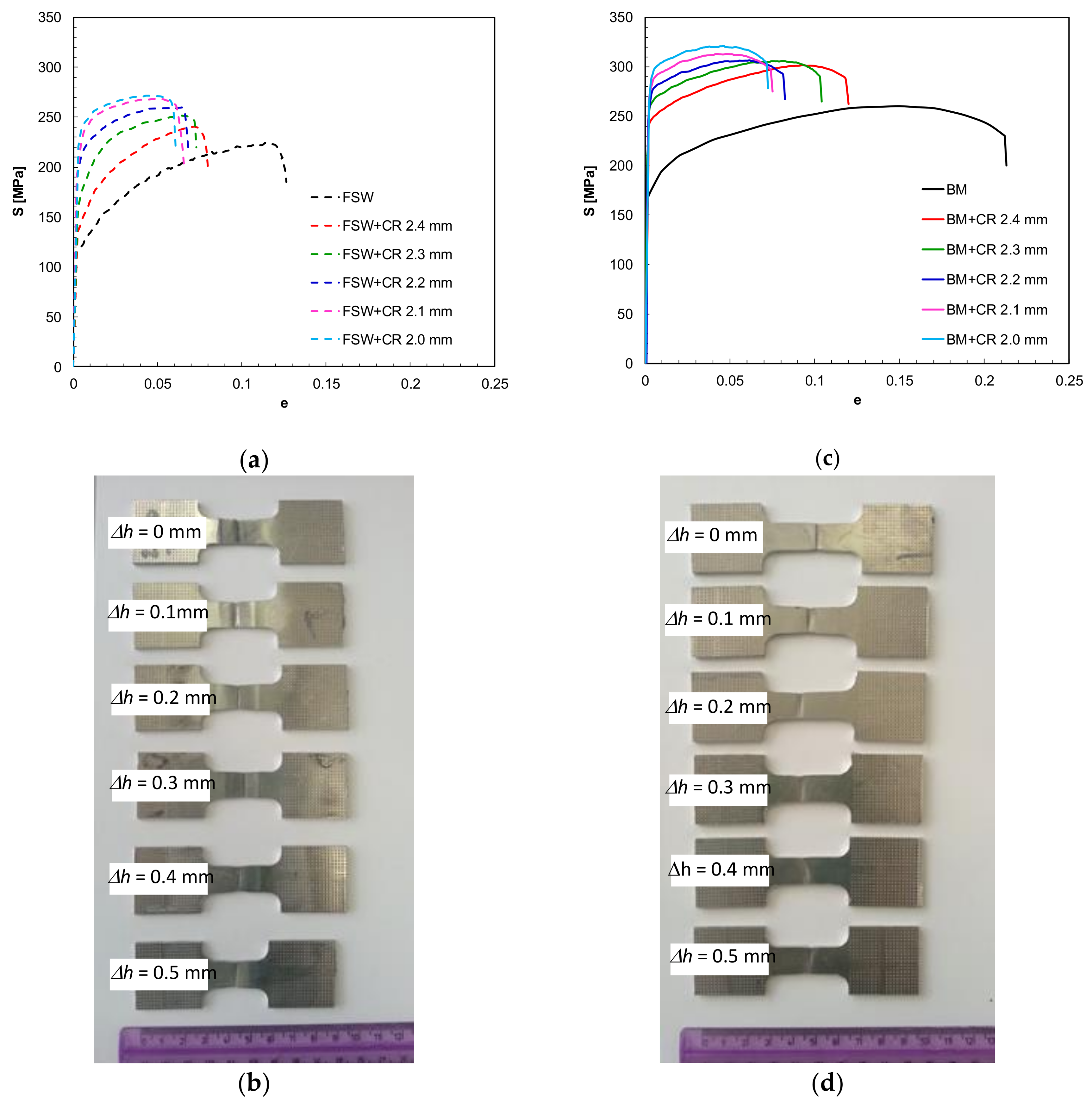
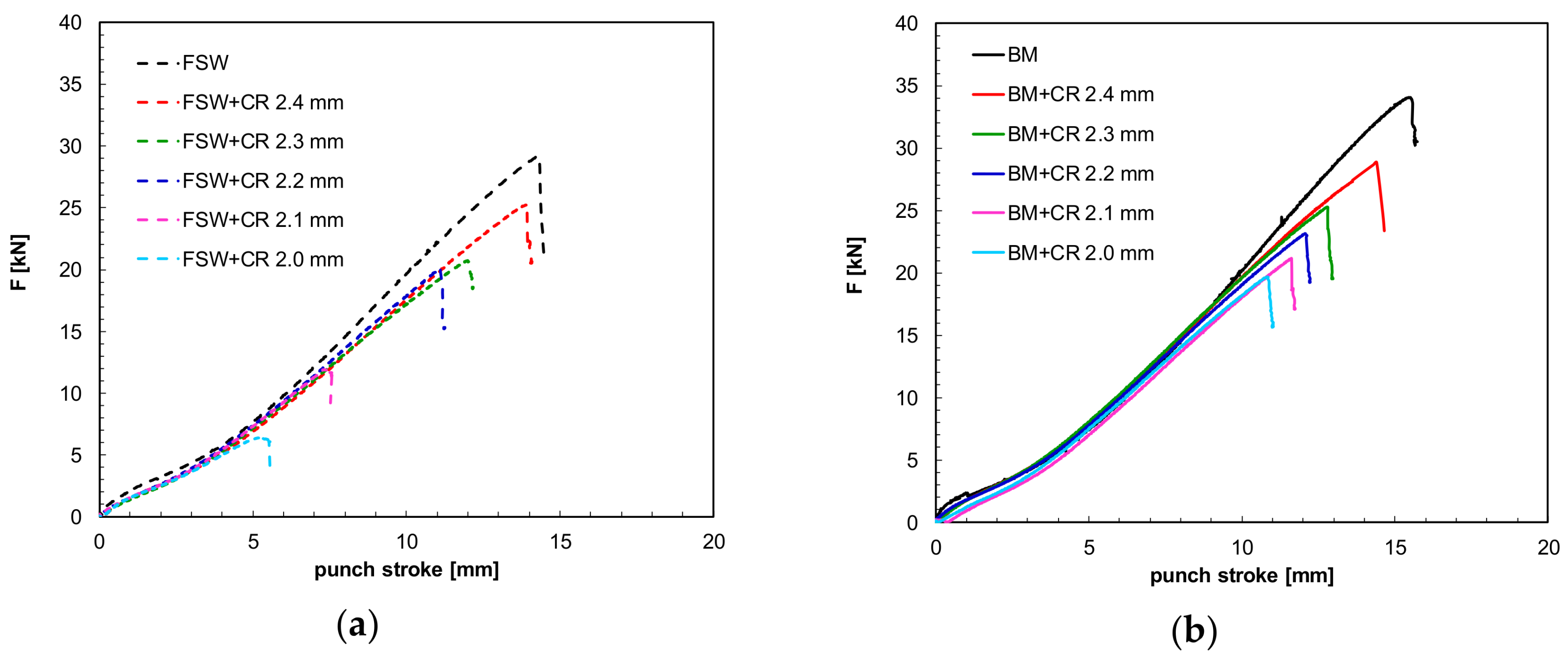
  • The yield strength and ultimate tensile strength in the FSWed+CRed condition are higher than those in the FSWed. Such discrepancy increases with the height reduction imposed by cold rolling. On the contrary, the ultimate elongation in the FSWed+CRed condition is lower than that in the FSWed, with a difference that grows with height reduction,
  • The yield strength, ultimate tensile strength, and ultimate elongation in the FSWed+CRed condition are lower than those in BM+CRed one.
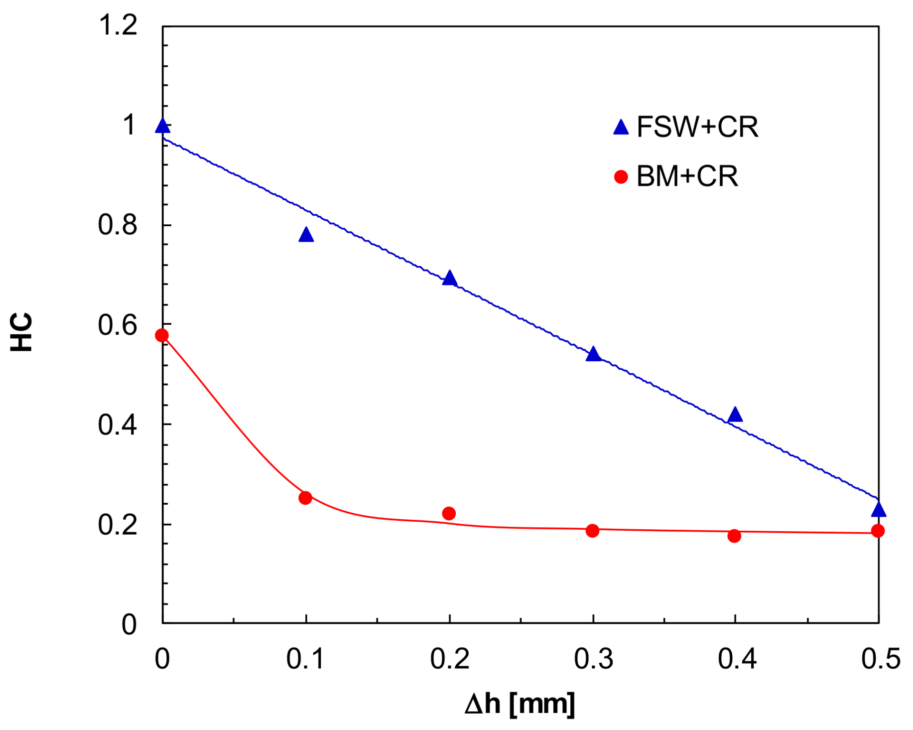
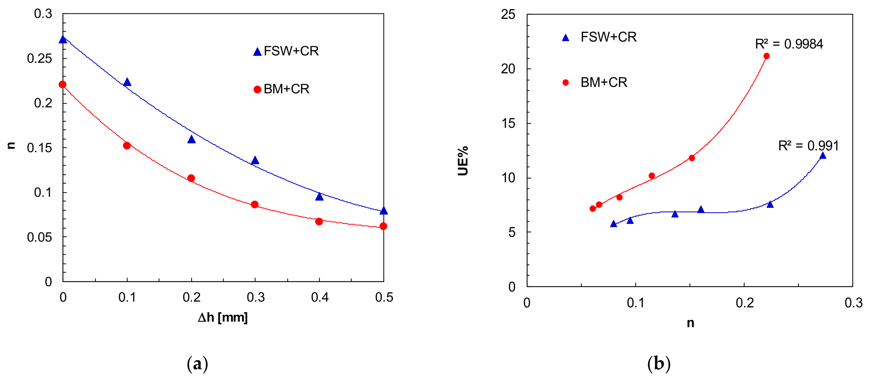
  • The mechanical behaviour is strongly affected to by the strain hardening caused by cold rolling. In particular, the strain hardening exponent and hardening capacity decrease with increasing height reduction with the FSWed+CRed condition characterised.
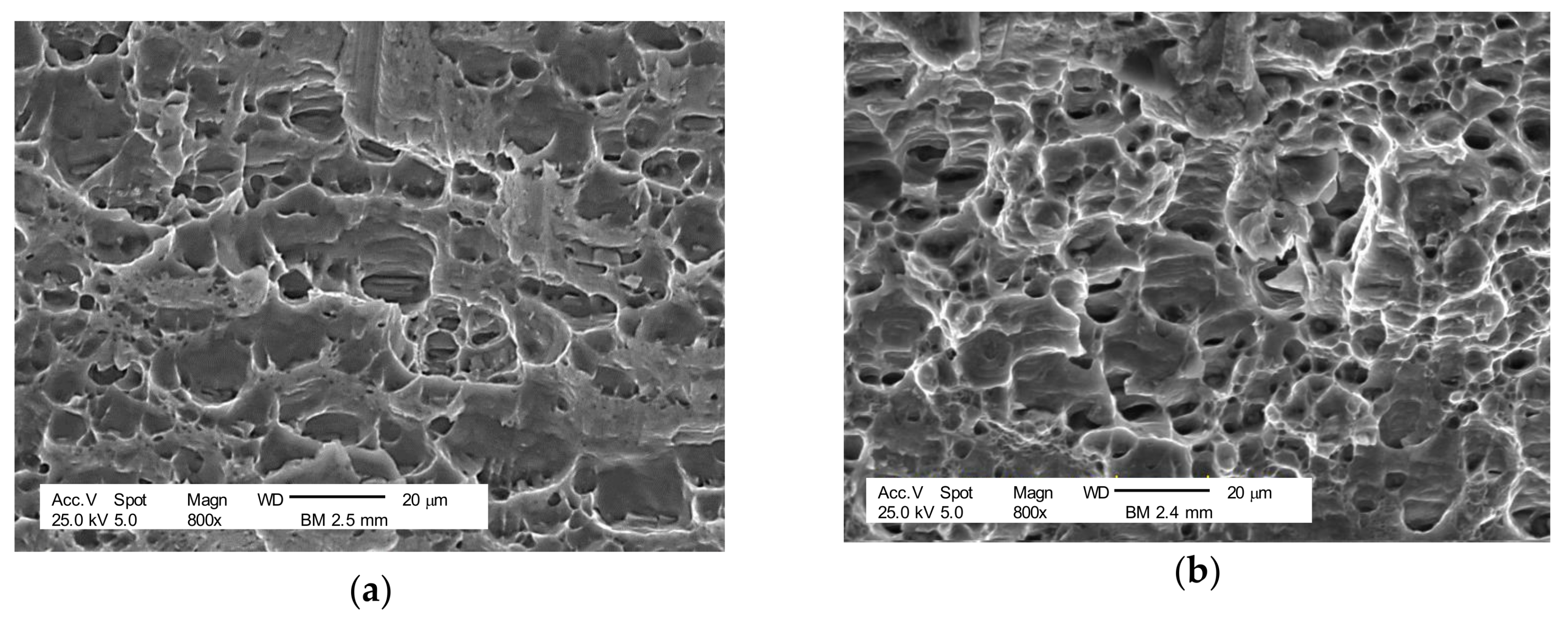
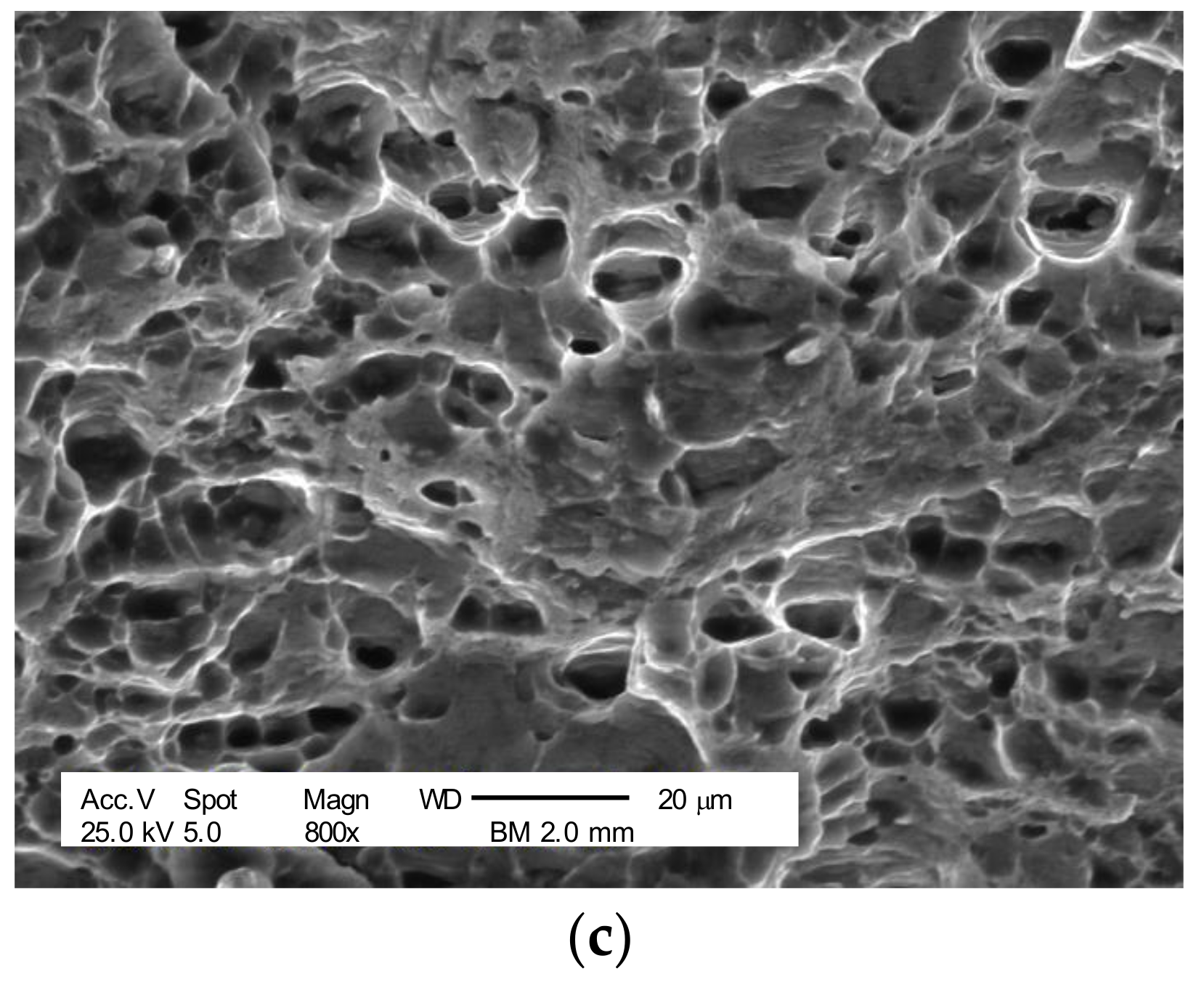
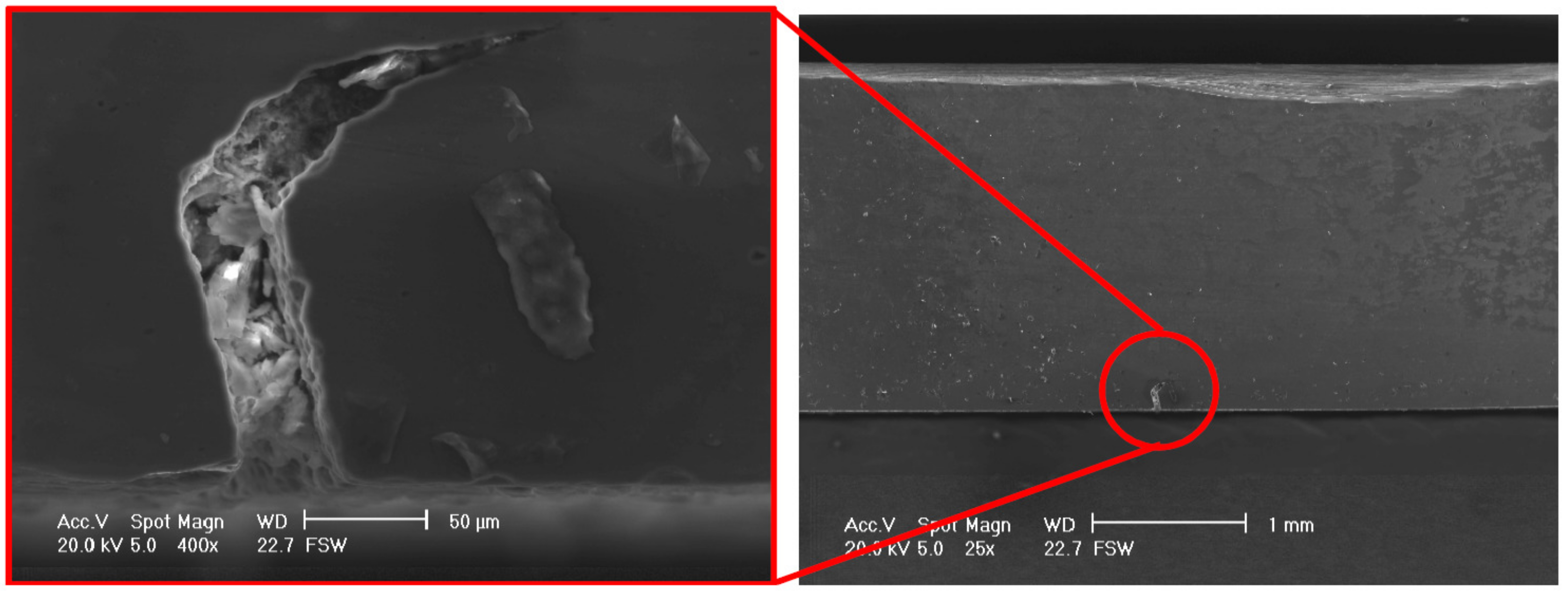
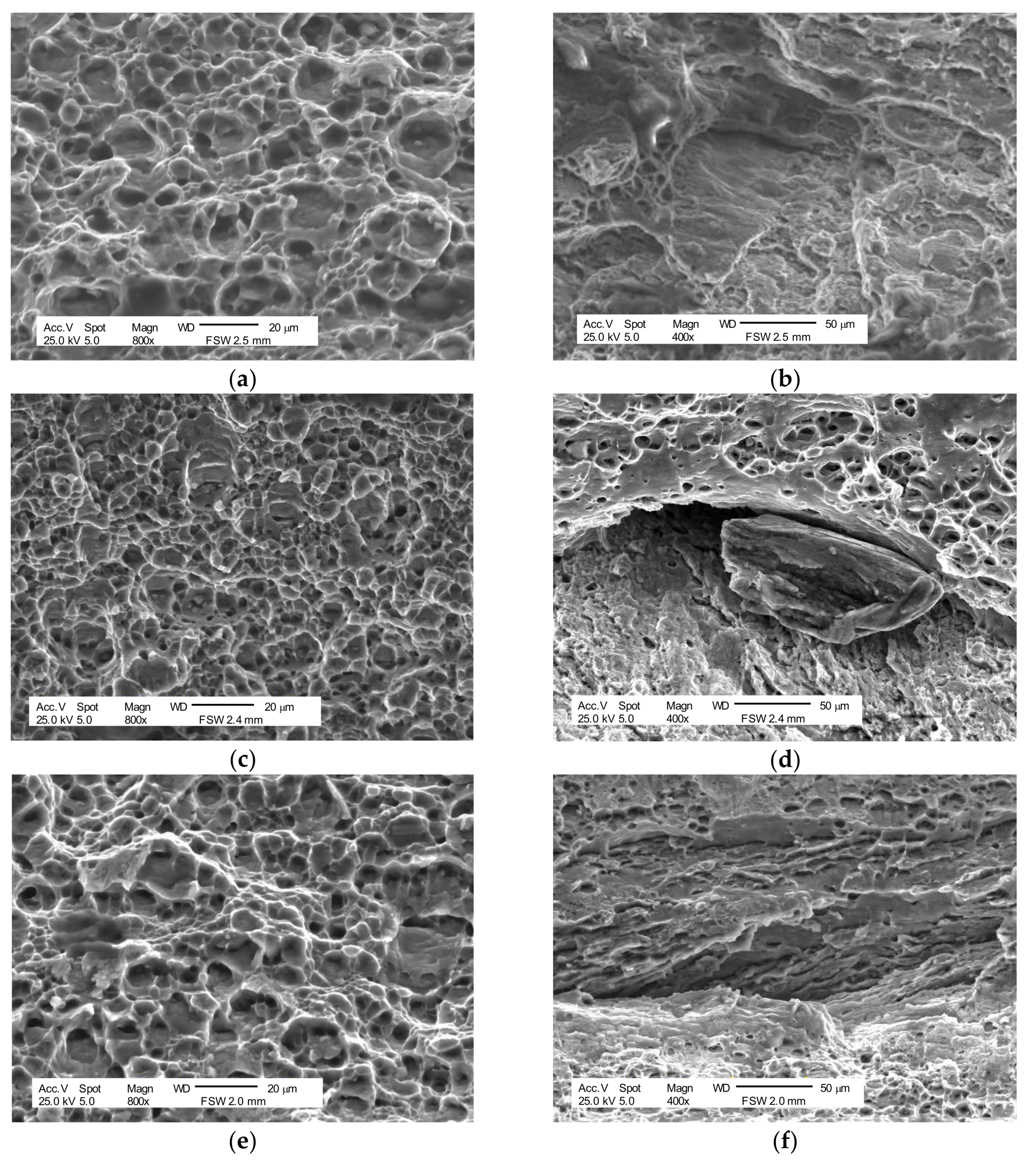
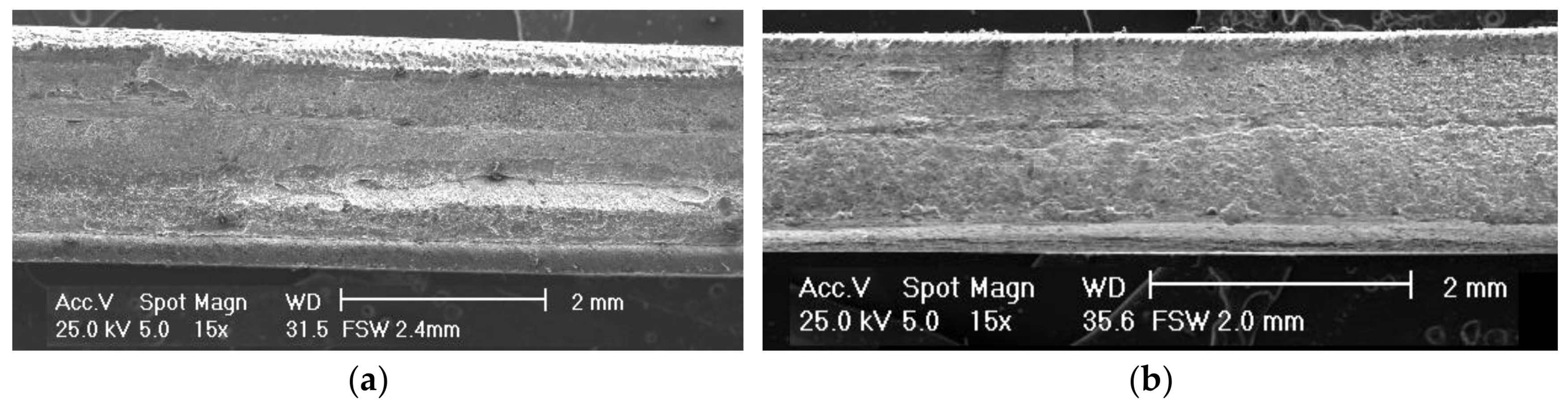
  • The SEM images of FSWed+CRed samples show a ductile behaviour with the microvoid coalescence even though cracks propagating along the direction of welding motion appears. The BM+CRed samples exhibit a ductile fracture surface morphology.
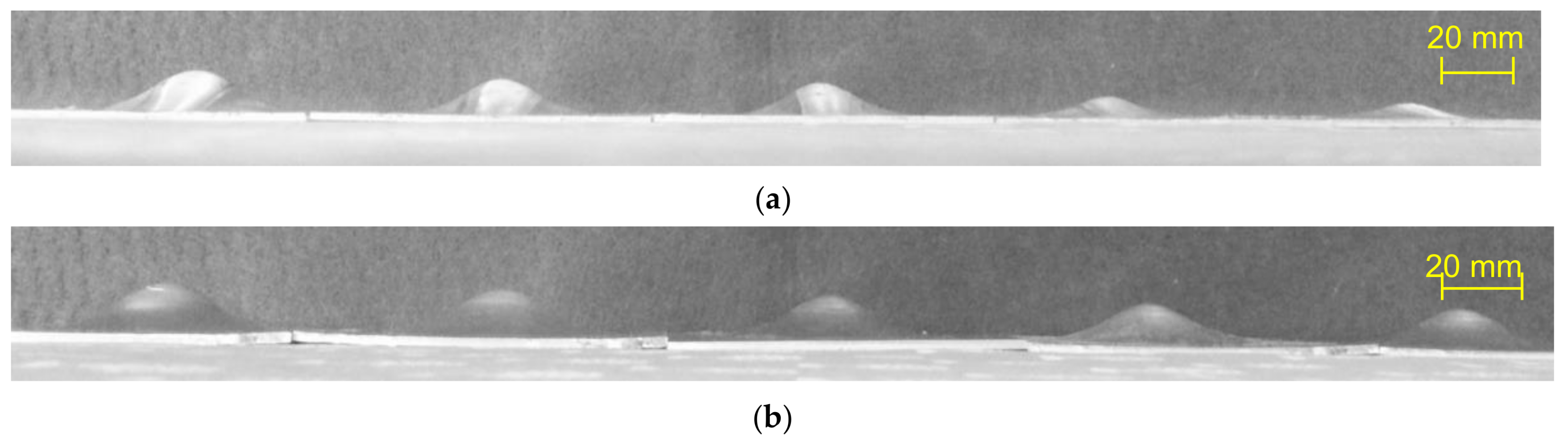
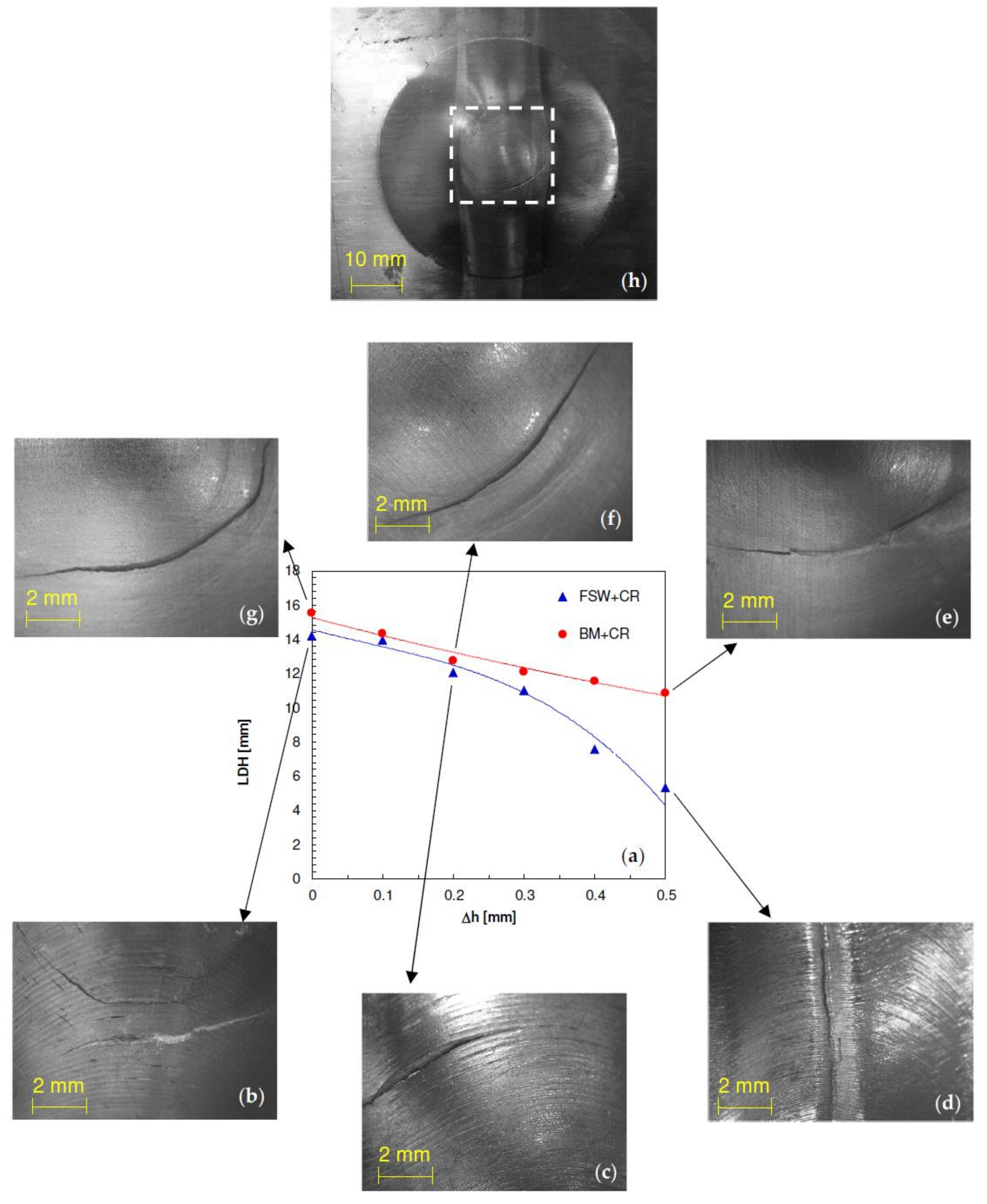
  • The limiting dome height decreases with increasing height reduction. In the FSWed+CRed condition the LDH values are slightly lower than those in the BM+CRed one until a height reduction of 0.2 mm; as Δh further increases, such discrepancy strongly grows.

Acknowledgments

Massimiliano Pieralisi, Luciano Greco, and Daniele Ciccarelli are acknowledged for their contribution in the experimental work.

Author Contributions

Mohamad El Mehtedi, Archimede Forcellese and Michela Simoncini conceived and designed the experiments; Mohamad El Mehtedi and Michela Simoncini performed the experiments; Michela Simoncini and Giuseppe Casalino analyzed the data; Archimede Forcellese wrote the manuscript, Archimede Forcellese and Michela Simoncini edited the manuscript.

Conflicts of Interest

The authors declare no conflict of interest.

References

  1. Mishra, R.S.; Ma, Z.Y. Friction stir welding and processing. Mater. Sci. Eng. R 2005, 50, 1–78. [Google Scholar] [CrossRef]
  2. Wonoh, L.; Kyung-Hwan, C.; Daeyong, K.; Junehyung, K.; Chongmin, K.; Kazutaka, O.; Wagoner, R.H.; Kwansoo, C. Experimental and numerical study on formability of friction stir welded TWB sheets based on hemispherical dome stretch tests. Int. J. Plast. 2009, 25, 1626–1654. [Google Scholar] [CrossRef]
  3. Padhy, G.K.; Wu, C.S.; Gao, S. Friction stir based welding and processing technologies—Processes, parameters, microstructures and applications: A review. J. Mater. Sci. Technol. 2018, 34, 1–38. [Google Scholar] [CrossRef]
  4. Mahdi Moradi, M.; Jamshidi Aval, H.; Jamaati, R.; Amirkhanlou, S.; Ji, S. Microstructure and texture evolution of friction stir welded dissimilar aluminum alloys: AA2024 and AA6061. J. Manuf. Process. 2018, 32, 1–10. [Google Scholar] [CrossRef]
  5. Contuzzi, N.; Campanelli, S.L.; Casalino, G.; Ludovico, A.D. On the role of the thermal contact conductance during the friction stir welding of an AA5754-H111 butt joint. Appl. Therm. Eng. 2016, 104, 263–273. [Google Scholar] [CrossRef]
  6. Forcellese, A.; Simoncini, M.; Casalino, G. Influence of process parameters on the vertical forces generated during friction stir welding of AA6082-T6 and on the mechanical properties of the joints. Metals 2017, 7, 350. [Google Scholar] [CrossRef]
  7. Bruni, C.; Forcellese, A.; Gabrielli, F.; Simoncini, M. Post-welding formability of AZ31 magnesium alloy. Mater. Des. 2011, 32, 2988–2991. [Google Scholar] [CrossRef]
  8. Forcellese, A.; Simoncini, M. Plastic flow behaviour and formability of FSWed joints in AZ31 thin sheets obtained using the “pinless” tool configuration. Mater. Des. 2012, 36, 123–129. [Google Scholar] [CrossRef]
  9. Simoncini, M.; Forcellese, A. Effect of the welding parameters and tool configuration on micro- and macro-mechanical properties of similar and dissimilar FSWed joints in AA5754 and AZ31 thin sheets. Mater. Des. 2012, 41, 50–60. [Google Scholar] [CrossRef]
  10. Kleiner, M.; Geiger, M.; Klaus, A. Manufacturing of lightweight components by metal forming. CIRP Ann. 2003, 52, 521–542. [Google Scholar] [CrossRef]
  11. Fratini, L.; Buffa, G.; Shivpuri, R. Improving friction stir welding of blanks of different thicknesses. Mater. Sci. Eng. A 2007, 459, 209–215. [Google Scholar] [CrossRef]
  12. Simoncini, M.; Ciccarelli, D.; Forcellese, A.; Pieralisi, M. Micro- and macro- mechanical properties of pinless friction stir welded joints in AA5754 aluminium thin sheets. Procedia CIRP 2014, 18, 9–14. [Google Scholar] [CrossRef]
  13. Lertora, E.; Gambaro, C.; Mandolfino, C.; Pedemonte, M. Friction stir welding between extrusions and laminates. Weld. Int. 2015, 29, 117–123. [Google Scholar] [CrossRef]
  14. Fratini, L.; Buffa, G.; Shivpuri, R. Finite element studies on friction stir welding processes of tailored blanks. Comput. Struct. 2008, 86, 181–189. [Google Scholar] [CrossRef]
  15. Guerra, M.; Schmidt, C.; McClure, J.C.; Murr, L.E.; Nunes, A.C. Flow patterns during friction stir welding. Mater. Charact. 2003, 49, 95–101. [Google Scholar] [CrossRef]
  16. Casalino, G.; Campanelli, S.; Mortello, M. Influence of shoulder geometry and coating of the tool on the friction stir welding of aluminium alloy plates. Procedia Eng. 2014, 69, 1541–1548. [Google Scholar] [CrossRef]
  17. Hirata, T.; Oguri, T.; Hagino, H.; Tanaka, T.; Wook Chung, S.; Takigawa, Y.; Higashi, K. Influence of friction stir welding parameters on grain size and formability in 5083 aluminum alloy. Mater. Sci. Eng. A 2007, 456, 344–349. [Google Scholar] [CrossRef]
  18. Cabibbo, M.; Forcellese, A.; Simoncini, M. New approaches to the friction stir welding of aluminum alloys. In Joining Technologies; Mahadzir, Ishak, Ed.; InTech: Rijeka, Croatia, 2016; pp. 7–26. [Google Scholar]
  19. Lertora, E.; Mandolfino, C.; Gambaro, C. Effect of welding parameters on AA8090 Al-Li alloy FSW T-joints. Key Eng. Mater. 2013, 554–557, 985–995. [Google Scholar] [CrossRef]
  20. Rodrigues, D.M.; Loureiro, A.; Leitao, C.; Leal, R.M.; Chaparro, B.M.; Vilaça, P. Influence of friction stir welding parameters on the microstructural and mechanical properties of AA 6016-T4 thin welds. Mater. Des. 2009, 30, 1913–1921. [Google Scholar] [CrossRef]
  21. Forcellese, A.; Fratini, L.; Gabrielli, F.; Simoncini, M. Formability of friction stir welded AZ31 magnesium alloy sheets. Mater. Sci. Forum 2010, 638–642, 1249–1254. [Google Scholar] [CrossRef]
  22. Simoncini, M.; Cabibbo, M.; Forcellese, A. Development of double-side friction stir welding to improve post-welding formability of joints in AA6082 aluminium alloy. Proc. IMechE B: J. Eng. Manuf. 2016, 230, 807–817. [Google Scholar] [CrossRef]
  23. Gabrielli, F.; Forcellese, A.; El Mehtedi, M.; Simoncini, M. Mechanical properties and formability of cold rolled friction stir welded sheets in AA5754 for automotive applications. Procedia Eng. 2017, 183, 245–250. [Google Scholar] [CrossRef]
  24. Ciarapica, F.; D’Orazio, A.; Forcellese, A.; Simoncini, M. Sustainability analysis of friction stir welding of AA5754 sheets. Procedia CIRP 2017, 62, 529–534. [Google Scholar] [CrossRef]
  25. Liu, H.J.; Fujii, H.; Maeda, M.; Nogi, K. Tensile properties and fracture locations of friction-stir-welded joints of 2017-T351 aluminum alloy. J. Mater. Process. Technol. 2003, 142, 692–696. [Google Scholar] [CrossRef]
  26. Spigarelli, S.; Paoletti, C. A unified physical model for creep and hot working of Al-Mg solid solution alloys. Metals 2018, 8, 9. [Google Scholar] [CrossRef]
  27. Armstrong, R.W.; Douthwaite, R.M. Hall-Petch basis for assessing alloy strengthening. In Grain Size and Mechanical Properties—Fundamentals and Applications; Otooni, M.A., Armstrong, R.W., Grant, N.J., Ishizaki, K., Eds.; Materials Research Society: Pittsburgh, PA, USA, 1995; pp. 41–47. [Google Scholar]
  28. Wang, S.C.; Zhu, Z.; Starink, M.J. Estimation of dislocation densities in cold rolled Al-Mg-Cu-Mn alloys by combination of yield strength data, EBSD and strength models. J. Microsc. 2005, 217, 174–178. [Google Scholar] [CrossRef] [PubMed]
  29. Afrin, N.; Chen, D.L.; Cao, X.; Jahazi, M. Strain hardening behavior of a friction stir welded magnesium alloy. Scr. Mater. 2007, 57, 1004–1007. [Google Scholar] [CrossRef]
  30. Ni, D.R.; Chen, D.L.; Wang, D.; Xiao, B.L.; Ma, Z.Y. Tensile properties and strain-hardening behavior of friction stir welded SiCp/AA2009 composite joints. Mater. Sci. Eng. A 2014, 608, 1–10. [Google Scholar] [CrossRef]
  31. Nandan, R.; DebRoy, T.; Bhadeshia, H.K.D.H. Recent advances in friction-stir welding—Process, weldment structure and properties. Progress Mater. Sci. 2008, 53, 980–1023. [Google Scholar] [CrossRef]
  32. Budai, D.; Tisza, M.; Zoltán Kovács, P. Investigation of the formability of EN AW 5754 aluminium alloy sheets with different thickness. In International Multidisciplinary Scientific Conference; University of Miskolc: Miskolc, Hungary, 2016; ISBN 978-963-358-113-1. [Google Scholar]
  33. Simoncini, M.; Panaccio, L.; Forcellese, A. Bending and stamping processes of FSWed thin sheets in AA1050 alloy. Key Eng. Mater. 2014, 622–623, 459–466. [Google Scholar] [CrossRef]
Figure 1. Experimental setup of the Friction Stir Welding (FSW) process.
Metals 08 00223 g001
Figure 2. Typical nominal stress vs. nominal strain curves and fractured tension tested samples: (a) S-e curves and (b) fractured samples in the FSWed+CRed condition; (c) S-e curves; and (d) fractured samples in the BM+CRed condition.
Metals 08 00223 g002
Figure 3. Comparison between the mechanical behaviour exhibited by the FSWed+CRed and BM+CRed samples in terms of: (a) Yield strength vs. height reduction; (b) Ultimate tensile strength vs. height reduction; (c) Ultimate elongation vs. height reduction.
Metals 08 00223 g003
Figure 4. Scanning electron microscope fractography of the FSWed and FSWed+CRed samples deformed along the cold rolling direction: (a) Δh = 0 mm (lower magnification); (b) Δh = 0 mm (higher magnification); (c) Δh = 0.1 mm (lower magnification); (d) Δh = 0.1 mm (higher magnification); (e) Δh = 0.5 mm (lower magnification); (f) Δh = 0.5 mm (higher magnification).
Metals 08 00223 g004
Figure 5. Scanning electron microscope fractography of the BM+CRed samples deformed along the cold rolling direction: (a) Δh = 0 mm; (b) Δh = 0.1 mm; (c) Δh = 0.5 mm.
Metals 08 00223 g005aMetals 08 00223 g005b
Figure 6. Punch load vs. stroke curves obtained by hemispherical punch test performed on: (a) FSWed+CRed and (b) BM+CRed samples.
Metals 08 00223 g006
Figure 7. Samples deformed by means of hemispherical punch test: (a) FSWed+CRed and (b) BM+CRed samples.
Metals 08 00223 g007
Figure 8. (a) Limiting dome height as a function of height reduction and (bh) typical fractures on deformed samples in both FSWed+CRed and BM+CRed conditions.
Metals 08 00223 g008
Figure 9. (a) Strain hardening exponent vs. height reduction and (b) correlation between ultimate elongation and strain hardening exponent in both FSWed+CRed and BM+CRed conditions.
Metals 08 00223 g009
Figure 10. Quantification of the strengthening contributions given by the different mechanisms.
Metals 08 00223 g010
Figure 11. Hardening capacity vs. height reduction in both FSWed+CRed and BM+CRed conditions.
Metals 08 00223 g011
Figure 12. Scanning electron microscope (SEM) images showing the discontinuity located in the bottom side of the weld before cold rolling.
Metals 08 00223 g012
Figure 13. Scanning electron microscope fractography of the FSWed+CRed samples deformed in the cold rolling direction: (a) Δh = 0.1 mm; (b) Δh = 0.5 mm.
Metals 08 00223 g013
Table 1. Chemical composition of AA AA5754 aluminium alloy (wt. %).
ZnCuMnSiFeMgCrTiNiAl
0.20.10.50.40.42.6–3.60.30.15-Bal.
Table 2. Geometric features of the conical pin tool in H13 tool steel used in the FSW experiments.
FeatureValue
Shoulder diameter [mm]15
Cone base diameter [mm]3.9
Pin height [mm]2.3
Pin angle [°]30
Table 3. Welding process parameters.
ParameterValue
Rotational speed [rpm]1200
Welding speed [mm/min]100
Tool sinking [mm]0.08
Plunging angle [°]2

