Article

Kinetics of Grain Boundary Networks Controlled by Triple Junction and Grain Boundary Mobility

1
Institute of Mechanics, Montanuniversität Leoben, Franz-Josef-Straße 18, A-8700 Leoben, Austria
2
Institute of Physics of Materials, Academy of Sciences of the Czech Republic, Žižkova 22, 616 62 Brno, Czech Republic
*
Author to whom correspondence should be addressed.
Metals 2018, 8(12), 977; https://doi.org/10.3390/met8120977
Submission received: 2 November 2018 / Revised: 19 November 2018 / Accepted: 20 November 2018 / Published: 22 November 2018

Abstract

:
The kinetics of a triple junction of grain boundaries with distinct specific energies and mobilities and a finite mobility of the triple junction is investigated. The microstructure is approximated by different 2D settings consisting of typical structural elements. First, the migration of the triple point together with the adjacent grain boundaries, is simulated, assuming that the grains are infinitely large. Secondly, growth or shrinkage of finite n-sided grains is simulated by altering the boundary conditions and the results are compared to the already published analytical solution. The numerical results coincide with the corrected analytical solution. This solution can be derived either by applying the principle of maximum dissipation, or by applying the force balance at the triple junction within the framework of linear irreversible thermodynamics. The change of the area of infinite and finite grains is investigated analytically and numerically. By comparing the results of both approaches, the influence of the initial topology of the structural elements on the kinetics of grain growth can be estimated. Furthermore, the kinetics of grain growth of different idealized grain boundary networks is investigated. It is shown that square shaped grains surrounded by hexagons and dodecagons result in a more realistic grain growth scenarios than squares surrounded by octagons. A deviation from idealized grain boundary arrangements is e.g., observed, due to different triple junction mobilities, and the initially n-sided regular grain deforms in a complex manner.

Graphical Abstract

1. Introduction

The development of modern steels (see e.g., references [1,2,3,4,5,6]), superalloys (e.g., references [7,8]) and other technologically important materials like intermetallics (e.g., reference [9]) and ceramics (e.g., reference [10]) depend on a profound understanding of the microstructural changes occurring during processing and operation. In general, fine grained homogenous microstructures rank among the desired features that allow for optimal mechanical properties of these functionally oriented materials. Thus, substantial grain growth must be avoided. Grain growth is driven by the tendency to decrease the total energy of the grain boundaries in the system.
These activities in materials research are nowadays complemented by computer simulations, in order to predict the evolution of the microstructure in general, or the kinetics of grain growth in particular [11]. Different simulation methods that are applicable to different length scales have been used to investigate the kinetics of grain growth numerically. Cellular automata (see e.g., references [12,13]) can be applied to simulate the kinetics of grain growth over the whole size range, and kinetic Potts Monte Carlo models (see e.g., references [14,15,16,17]) and phase field models (see e.g., references [18,19,20,21]) are used from micrometer to nanometer scale. Vertex models (e.g., references [22,23] and level-set models (e.g., references [24,25,26,27,28]) can be applied from the sub-micrometer range to the millimeter-range.
Two different approaches are mainly followed when modeling the kinetics of grain growth, in order to obtain a deeper understanding of the underlying physics of these processes. On the one hand, the kinetics of grain growth can be calculated by deriving a steady state grain size distribution and the respective rate law (see e.g., reference [29]). Grains are usually approximated by spheres with a certain radius. The kinetics of normal grain growth can be described by this concept. However, as pointed out in reference [30], it is not in the scope of such a concept to provide topological information, e.g., the actual shape and the number of boundary facets that comprise the grain. On the other hand, it is a challenging but rewarding task to investigate the motion of individual grain boundaries that terminate at triple junction lines of finite mobility (see e.g., references [31,32]). The influence of the triple junction mobility on 2-D grain growth kinetics is investigated by the means of a phase field model in reference [33]. The effect of grain boundary anisotropy on highly textured grain structures is studied by phase field modeling in reference [34]. They observed that different types of triple and quadruple junctions occur due to different magnitudes of anisotropy in the grain boundary energy. Meanwhile, triple and quadruple junction mobility influenced grain growth in polycrystalline materials has been investigated, e.g., by phase field models [33], level-set models [35], vertex models [36,37,38,39,40], cellular automata [41], statistical methods [42], Monte Carlo Potts models [41,43,44,45], and by molecular dynamics simulations [46].
Following Fischer et al. [31] a system with cylindrical symmetry is assumed where three grain boundaries coincide at a triple junction line. This line degenerates to a triple point, and the grain boundaries become lines in a 2D section, which corresponds to sections on micrographs. General contact conditions at the triple junction are derived from the thermodynamic extremal principle in reference [31]. Barrales-Mora et al. [32] consider special geometrical arrangements and assume that all grain boundary mobilities, and specific energies are equal. It is demonstrated in this work that the general contact conditions at the triple junction [31] result in the special conditions used in reference [32] provided that Equation (12) of reference [32], and the following derivations are corrected.
Different boundary conditions (i.e., infinitely elongated grain boundaries in the first case [31] and symmetrical boundary conditions in the second case [32]) are applied to the triple junction kinetics. The evolution of quantities related to grain growth kinetics, e.g., the change of surface area, are evaluated for both cases and compared.
Real 2D-microstructures consist of a plane-filling, irregular network of grain boundaries, see e.g., Figure 1 in Hillert’s lecture [29]. It was argued in previous works that the relative energy of a grain boundary and its total area in the polycrystalline material is inversely related, see e.g., references [47,48]. The energy of a grain boundary was estimated by measuring the dihedral angle of thermal grooves [48]. It turned out that a specific grain boundary that lengthens due to its topological surroundings has a lower energy than those grain boundaries that tend to shorten. Simulations of the evolution of the grain boundary network become more realistic when both the lengthening and shortening grain boundary topologies are present during different stages of grain growth. These microstructural changes are obtained by introducing an asymmetry in the grain boundary network. This asymmetry is due to a square-shaped grain being surrounded by hexagons and dodecagons instead of equilateral octagons. The according grain boundary network is modeled by a triple junction and the three adjacent grain boundaries only.

2. Problem Description and Methods

2.1. Geometrical Setting

The initial geometrical setting is shown in Figure 1 for the special case of a four-sided grain. Three grain boundaries meet at a triple point in a two-dimensional section. The grain boundaries are assumed to be perpendicular to the plane of projection. Grain boundaries 1 and 3 are initially perpendicular to each other, and grain boundaries 1 and 2 and grain boundaries 2 and 3, respectively comprise an angle of 3 π / 4 . Two different boundary conditions, case I and case II, are assumed to be valid in the geometrical setting:
Case I: The grain boundaries are fixed at their centers. This constraint is applicable as long as these centers are sufficiently far away from the triple points. These boundary conditions imply that the grains are assumed to be infinitely large (Figure 1a).
Case II: The left half of grain boundary 1 and the upper half of grain boundary 3 are mirrored at the horizontal and vertical symmetry lines (Figure 1b). Due to the symmetry of the arrangement, only the upper left quarter of the shrinking grain is investigated.

2.2. Triple Junction Relations

The unit vectors e _ 1 , e _ 2 and e _ 3 indicate the direction of the grain boundaries at the triple point. These unit vectors are characterized by the angles, which they enclose with the x-axis in the 2D setting; see Figure 2a. The halves of the grain boundaries 1 and 3 adjacent to the triple point are presented in Figure 2. The vertical and horizontal symmetry planes of the grain boundaries 1 and 3, respectively are depicted by dashed lines. The notation for the directions and the angles used in Figure 2a corresponds to the notation introduced in reference [31], whereas the angles depicted in Figure 2b correspond to the notation in reference [32] with the dihedral angle θ and the turning angle β. The direction of the unit vector e _ 3 and the y-axis is enclosed by the angle α.
The curvature of grain boundary 1 at the triple point is denoted by κ 1 . Grain boundary 2 remains straight at any time and grain boundary 3 corresponds to grain boundary 1 mirrored at a plane perpendicular to grain boundary 2 (dash-dotted line in Figure 2). The curvature κ 1 occurring in grain boundary 1 at the triple point is related to the distance a by Equation (11) from reference [32] repeated here:
κ 1 = 1 r 1 = 2 sin α a
Following reference [32] the dimensionless parameter Λ can be introduced:
Λ = m T a m g b
where Λ is a measure for the rate—controlling processes of the grain growth kinetics. The kinetics is controlled by processes at the grain boundary only for large values of Λ , whereas for small values of Λ , the kinetics is controlled by processes at the triple point, i.e., by the mobility of the triple point. The value Λ is small in the case of a comparably small mobility of the triple point, and decreases, since the value of the quantity a decreases during the shrinkage of a grain. Therefore, another normalized quantity Λ ¯ is defined in this work, which does not depend on the actual grain size, but only depends on the ratio of a normalized mobility of the triple point and a normalized grain boundary mobility:
Λ ¯ = Λ a a 0 = m T m gb a 0
with a 0 being the initial value of a .
The dimensionless parameter Λ can be expressed as a function of angle β by substituting a and the ratio m T / m g b by the means of Equations (1) and (2) with the angles α 1 , α 2 , and α 3 formulated as functions of the angles α and β : α 1 = π + α , α 2 = 7 π / 4 , and α 3 = β + α , and α is a function of β : α = π / 4 β / 2 .
Λ = 2 [ sin ( π 4 β 2 ) ] cos ( β 2 ) [ 2 sin ( β 2 ) 1 ]
This result is obtained from simplifying the general contact conditions at the triple point as derived from the thermodynamic extremal principle in reference [31].
Now let us follow the approach described in reference [32]. The geometry of the motion of the grain boundaries and the triple point is depicted in Figure 3. The net driving force P acts in the x’-direction. The triple point can only move in the x’-direction. The velocity v tp of the triple point and the point of grain boundary 1 adjacent to the triple point have to be the same for a concomitant motion of the triple point and grain boundary 1. From Figure 2, it follows that the normal velocity v n of grain boundary 1 at the triple point is the normal projection of velocity v tp of the triple point in the direction perpendicular to grain boundary 1. Thus, both velocities v tp and v n are related via angle θ / 2 :
v tp = v n sin ( θ / 2 )  
The angle ( θ / 2 = π / 4 + α ) equals φ in Equation (12) of reference [32]. Thus, the term sin φ = sin ( θ / 2 ) should be in the denominator as in Equation (6), and not in the numerator, as in Equation (12) of reference [32], or in the same equation, Equation (26) of reference [35].
The velocity v tp at the triple point is linearly proportional to the net driving force P:
v tp = m T P = m T γ [ 2 cos ( θ / 2 ) 1 ]  
and the grain boundary velocity is proportional to the curvature κ 1 :
v n = m gb γ κ 1 = m gb γ 2 sin α a  
By combining Equations (6)–(8) the velocity v tp of the triple point is related to the grain boundary mobility m gb :
v tp = m gb γ 2 sin α a [ sin ( θ / 2 ) ]
The parameter Λ follows from equating Equations (7) and (9):
Λ = 2 sin α sin ( θ 2 ) [ 2 cos ( θ 2 ) 1 ] = 2 [ sin ( π 4 β 2 ) ] cos ( β 2 ) [ 2 sin ( β 2 ) 1 ]  
Thus, as expected, both approaches [31] and [32] result in the same expression for the parameter Λ .

2.3. Growth and Shrinkage of Polygonal Grains

Two-dimensional grain growth can be described by a further quantity, the rate of area change, A ˙ . Mullins [49] assumed that the velocity of the grain boundary is proportional to the mean curvature, and derived the von Neumann-Mullins relations from the following general equation based on geometrical considerations (see also Figure 4):
A ˙ = m gb γ [ ( β 11 β n 1 ) + ( β 22 β 12 ) + ( β 33 β 23 ) + + ( β n n β ( n 1 ) n ) ]  
where n is the number of sides or vertices of the grain.
The rate of area change A ˙ 1 and A ˙ 2 for the two cases I and II can be calculated from Equation (11). The geometry of the grain boundaries close to the triple point are shown in Figure 1a for case I. The rate of area change, A ˙ 1 equals:
A ˙ 1 = m gb γ [ n β ( 2 π n ϑ ) ]  
with the angles β and ϑ as shown in Figure 5a. The number of edges of the polygon is denoted by n.
For case II (depicted in Figure 5b), the rate A ˙ 2 of area change for the shrinking grain follows as:
A ˙ 2 = m gb γ ( n β 2 π )  

2.4. Normalized Time

For the sake of comparability with different initial situations (e.g., small grains or large grains, small or large ratios of the triple point mobility to the grain boundary mobility) a set of normalized quantities, e.g., Λ ¯ and Λ , are already introduced in a previous paragraph. The Two-dimensional growth and shrinkage of polygonal grains is described by the evolution of the grain area versus time. It is thus convenient to introduce a normalized time t ¯ . This dimension-free time t ¯ is normalized by the time τ :
τ = A 0 m gb γ  
where A 0 is the initial area of the polygonal grain.

2.5. Numerical Method

The contact conditions at the triple point are provided in reference [31]. The normal coordinate v i n of the velocity of grain boundary i at the triple junction is as follows:
v i n = m gb , i γ i κ i  
The velocity v _ T of the triple junction is expressed as
v _ T = m T i = 1 3 γ i e _ i  
with i = 1 , 2 , 3 being the number of the grain boundary.
The normal coordinate v i n ( s i ) of the velocity of grain boundary i at position s i is as follows:
v i n ( s i ) = m gb , i γ i κ i ( s i )  
The position of each nodal point j at the grain boundary i is given by a position vector r _ i j , and the differential equations are integrated numerically. The nodal points at the grain boundaries far from the triple point are fixed in reference [31], which allows for case I calculations. Symmetric boundary conditions are implemented in this work. An additional node “0” is introduced at grain boundary i. This node “0” has to move in such a way that it is always at a symmetrical position compared to node “2” with respect to the symmetry line (Figure 6). Various topological situations have been investigated by the extended network model in this work.

3. Results

3.1. Shrinkage of a 4-Sided Grain

The special case of the growth or shrinkage of a 4-sided grain (see also Figure 2) is investigated by the means of this extended version of the numerical routine described in reference [31], and by solving Equation (5). The positions of the triple point and of the grain boundaries at different times t ¯ are plotted in Figure 7a (case I) and Figure 7b (case II) for Λ ¯ = 2 . The kinetics of the shrinking grain is similar for both cases I and II for time t ¯ 0.125 , as the change in area is dominated by processes in the vicinity of the triple point. The assumption of infinitely elongated grains however, fails for t ¯ > 0.125 at Λ ¯ = 2 . Then, the kinetics of a shrinking quadratic grain must be described by the symmetry boundary conditions of case II. The initial turning angle β = π / 2 of the initially quadratic grain becomes small during the shrinkage of the grain until it reaches its optimum value, dependent on the actual grain size.
This value of β increases with increasing time and approaches β = π / 2 again before the grain vanishes; compare also with reference [32]. Let us look at two 4-sided grains with the same a-value. The turning angle β will be smaller for a high value of Λ ¯ , i.e., a high triple point mobility compared to a low one.
The plots shown in Figure 8 correspond to different Λ ¯ -values. At the beginning of the simulations, the grain boundaries are straight, with grain boundaries 1 and 3 being perpendicular to each other in all cases. The simulated curves meet the analytical result from Equation (5) within numerical accuracy. The equation proposed in reference [32] differs slightly from the curve according to Equation (5), due to the error described above.
In the following, the rate of area change A ˙ as a function of time t ¯ is determined numerically for both cases I and II, and for different values of Λ ¯ , as shown in Figure 9a,b. For a given value Λ ¯ , the curves for case I and case II overlap before a certain time t ¯ is exceeded. The kinetics is controlled by the triple point mobility at the early shrinking stage. The deviation of the curves for the two cases is reached after a very small time t ¯ in the case of a very high Λ ¯ -value, i.e., Λ ¯ = 2 × 10 7 . This deviation takes place after a longer time period at moderate values of Λ ¯ , i.e., Λ ¯ = 2 . The rate of area change A ˙ becomes constant for a long period of time t ¯ (Figure 9b) for very small values of Λ ¯ , i.e., Λ ¯ = 2 × 10 4 . These constant values are different for both cases I and II.
The shrinkage of the area of the grain is calculated according to Equation (5) for four different Λ ¯ -values, a very high Λ ¯ = 2 × 10 4 , a medium value ( Λ ¯ = 2 ), a low value ( Λ ¯ = 1 ), and an even smaller value ( Λ ¯ = 0.2 ). The shrinkage of the normalized area A / A 0 for Λ ¯ = 2 10 4 and Λ ¯ = 2 versus time t ¯ is plotted in Figure 10a. The area shrinkage for Λ ¯ = 1 and Λ ¯ = 0.2 is presented in Figure 10b. A-square shaped object with A = A 0 is the starting configuration for the numerical calculations. The analytical results start from a value higher than unity, since the angle β is smaller than π/2, meaning that the area of the curved segments is to be added to area of the square. The numerical results of both cases, Λ ¯ = 2 , and Λ ¯ = 2 × 10 4 , approximate the analytical solutions based on Equation (5).
It is demonstrated that the error made in [32] does not alter the analysis qualitatively, but quantitatively. Both analytical results—the first according to Equation (5), and the second from Equation (14) of reference [32]—cannot be distinguished for Λ ¯ = 2 × 10 4 , but they differ for Λ ¯ = 2 and the deviation becomes larger with decreasing Λ ¯ -values, as shown in Figure 10b.
It is remarkable that the analytical solution according to Equation (5) and the numerical analysis result in the same extinction times for A / A 0 . Although the area for the 4-sided grain with the ideally bulged grain boundaries is larger than the square-shaped object it shrinks faster on average, so that the same extinction time is reached. This is markedly clear for the blue continuous line (numerical result), and the dot and dash line (analytical result) for Λ ¯ = 2 × 10 4 .
Zöllner and Rios [43] investigated the influence of the triple junction mobility on grain growth by the means of a square-lattice Monte Carlo Potts model. They developed a self-similar function relating the number of neighboring grains to the radius change rate. In addition, Streitenberger and Zöllner [44] derived von Neumann-Mullins-type evolution for 3D polycrystalline grain microstructures. Whereas the area A is a linear function of time for infinite triple junction mobilities, they found that the radius R depends linearly on time for low triple junction mobilities. Thus, the ratio of grain radius R / R 0 , with R 0 being the initial radius, is numerically calculated and plotted versus time t ¯ in Figure 11. It is also observed that the function R / R 0 of t ¯ becomes closer and closer to a linear relation, the smaller the values of Λ ¯ are. A deviation from this linear function is observed for very small grain radii only, at least for the Λ ¯ -values investigated in this work. Novikov [42] states that grain growth affected by a finite mobility of boundary junctions occurs at three stages. The first stage is controlled by quadruple junctions, the second linear stage by triple junctions, and the third by finite grain boundary mobility. The results presented in Figure 11 seem to reveal the second and also the third stage of grain growth kinetics.

3.2. Kinetics of Polygonal Grains

The shrinkage of a regular pentagon and the growth of a regular heptagon and an octagon is investigated by the means of the extended numerical routine and case I and case II are compared. The initial area A 0 = a 0 2 is set to be the same for all polygons: square, pentagon, heptagon, and octagon. This means that a 0 is the half length of one side of the initially quadratic grain, but a 0 is larger than an edge side, in the case of polygons with n > 4 and smaller for n = 3. The unit cell for the grain boundaries of a shrinking pentagon is plotted in Figure 12 for Λ ¯ = 2 . As expected and verified by comparing the position of the grain boundaries of Figure 12 and Figure 8 the 4-sided grain shrinks faster than the 5-sided grain. The curvatures of the grain boundaries become more concave for the 4-sided grain compared to the 5-sided grain. The positions of the grain boundaries for case I are only comparable to the positions of the shrinking grains according to case II for small values of time.
The unit cell for grain boundaries of a growing heptagon is plotted in Figure 12 for Λ ¯ = 2 .
The octagon is growing much faster than the heptagon, which becomes evident by comparing the growth kinetics of the 7-sided and the 8-sided grain (Figure 13b and Figure 14b). The grain boundaries exhibit a stronger convex curvature between the triple points for the polygon with the higher number of edges. The grain boundaries have already reached their final position after t ¯ = 0.25 for the heptagon (Figure 13a) and the octagon arrangements (Figure 14a), assuming infinite grains, i.e., case I. Thus, the assumption of finite grains is only valid for rather small values of time for these cases.
The growth of the initially regular heptagon and octagon, and the shrinkage of the pentagon and the square are shown in Figure 15, where the relative area A / A 0 is plotted versus normalized time t ¯ . The insert is a magnification of the situation at small times t ¯ . In the case of shrinking grains, case I approximates case II for a time t ¯ 0.025 , and the curves deviate at very small times for growing grains.

3.3. Growth and Shrinkage of Grains Depending on the Surrounding Grain Arrangement

It is possible to describe the grain growth of different idealized grain arrangements by investigating the motion of the triple junction and the adjacent grain boundaries. It is tacitly assumed in Section 3.1 that the initially quadratic grain is surrounded by octagons (Figure 16a), case A. However, the surface plane could alternatively be filled by quadratic grains surrounded in alternating order by hexagons and dodecagons (Figure 16b), case B. The dodecagons might represent huge grains as they can occur during abnormal grain growth. The time-dependent displacement of the grain boundaries is depicted in Figure 17a for both arrangements A and B for Λ ¯ = 2 . The shrinkage of the area is plotted versus time for both cases in Figure 17b.
It is worth noting that the grain arrangement A will degenerate to a surface tessellated by larger quadratic grains as the original octagons become squares and the original squares vanish. The initially quadratic and then rectangular grains in arrangement B will degenerate to a single grain boundary connecting triangular grains with each other and separating dodecagonal grains. These dodecagons will possess larger and smaller edges. In a next step the smaller edges of the dodecagons will grow as the triangles shrink and this will finally result in a surface tessellated by hexagons (Figure 18a). The plane tessellated by dodecagons and triangles is represented by a “unit-cell” with two grain boundaries having the length of the half sides of the equilateral triangle, and the third grain boundary being the half of the smaller edge of the dodecagon (see Figure 18a, the “unit-cell”, is highlighted). The shrinkage of the triangle has been investigated numerically for Λ ¯ = 2 , and is shown in Figure 18b. The area A 0 of the initial triangle is the same as that of the initial square. It is evident that the 3-sided grain shrinks at a faster rate than the 4-sided grain, when comparing Figure 7b and Figure 18b.
In addition, the influence of different mobilities of distinct triple junctions on grain kinetics is investigated. The initially quadratic grain (arrangement B) is subjected to grain shrinkage. The distorted network is calculated for a short time t ¯ = 0.0625 , with the assumption of case I, i.e., infinitely large elongated grains is still valid. A direct connection of several sets of triple junctions and adjacent grain boundaries would allow for longer simulation times, and is planned for future work. However, we consider that case I already does allow for drawing certain conclusions with respect to the effect of different triple junction mobilities on the growth kinetics. The initial and the deformed grain boundary structures are depicted in Figure 19. Different triple junction mobilities in the points A, B, C, and D are considered by the following Λ ¯ -values; Λ ¯ = 0.2 in junction A, Λ ¯ = 200 in junction B, Λ ¯ = 2 in junction C, and Λ ¯ = 20 in junction D. It is evident from Figure 19 that simply by assuming different mobilities of the triple junctions, the symmetry of the arrangement is completely broken. The grain boundaries at triple junction A and triple junction A almost remain at their initial position due to their low Λ ¯ -value, and the junctions with higher mobilities markedly move and the angles between the grain boundaries come closer to the ideal value of 2π/3. The kinetics of any triple junction with its three adjacent grains—controlled by the mobility of the triple junction—is also influenced by the motion of the neighboring grain boundaries and triple junctions in a complex manner. Already after short time of investigation it is clear that the triple points will not follow straight but curved trajectories during the shrinkage of the grain.

4. Discussion

The growth or shrinkage of n-sided polygonal shaped grains is investigated. Boundary conditions for infinitely elongated grains are applied in case I. The curvature of the grains remains continuous at the centers of the grain boundary by applying symmetry boundary conditions in case II. The results coincide in a first stage, but already at small values of the normalized time t ¯ growth kinetics diverge for both cases. The deviation increases with increasing turning angle β (i.e., with increasing number n of the n-sided polygon. It is thus possible to mimic the initial stage by setting the angles α 1 , α 2 and α 3 at the triple junction and assuming infinite grains. However, for later stages of the growth it is crucial to implement the (local) grain topology by appropriate boundary conditions.
The shrinkage of the area with time is almost similar for both arrangements A and B (Figure 17a), i.e., the area shrinkage of the initially quadratic grains does not depend on the surrounding grains. This result is a direct consequence of the Neumann-Mullins topological expression, Equation (10), with the sum of the turning angles in asymmetric case B being similar to the sum in symmetric case A. However, the evolution of the shape of the initially quadratic grain strongly depends on the surroundings. The quadratic shape is conserved for arrangement A whereas the initially quadratic grain becomes rectangular for arrangement B during shrinkage. The quadratic shape for arrangement B would be conserved only in case that grain boundary between the dodecagon and the hexagon (short dotted line in Figure 17a) is immobile, e.g., by particles that effectively pin this grain boundary. It is remarked in reference [32] (p.551) that “equiangular hexagonal grains are completely static and can only evolve through topological interactions with neighboring grains”. An example for such a topological change is presented in arrangement B, where the equiangular hexagonal grains change their shape due to the growth of the dodecagons and the shrinkage of the squares.
The description of grain growth in two dimensions becomes more realistic, the greater the number of different polygonal grains that are introduced into a single model (e.g., dodecagons, hexagons, and squares are more realistic than dodecagons and squares). This result for grain growth is qualitatively comparable to the findings of Glicksman [50], where they succeed in describing three dimensional grain boundary structures by average n-hedra. This constructible or non-constructible, but mathematically defined n-hedra, is used as a topological proxy of network polyhedral that contain the same number of faces [51,52].
Different grain topologies can be introduced by setting appropriate boundary conditions. The kinetics of grain growth is simulated and applied to idealized grain boundary networks. The following results are obtained:
(1)
The dimensionless parameter Λ describing the shrinkage of an n-sided (here 4-sided) equilateral polygon is derived from the thermodynamic extremal principle, according to reference [31] and from the force balance following reference [32], and after correcting equations, both approaches lead to the same result.
(2)
It is demonstrated that the motion of the triple junction and the adjacent grain boundaries can be used to realistically simulate the growth kinetics for only a small period of time, when the boundary condition corresponding to infinitely large grains is used.
(3)
Triple point and adjacent grain boundary “unit-cells” have been constructed for 4-sided, 5-sided, 7-sided, and 8-sided equilateral polygonal grains. In accordance with theory, the grains with n < 6 shrink, whereas grains with n > 6 grow. The grain boundaries are curved positively (convex out of the grain) for n < 6, and negatively (concave into the grain). Here, it is tacitly assumed that the surrounding grains alter their topology in a completely symmetrical manner.
(4)
The final time of grain extinction is the same no matter whether the 4-sided grain starts at its bulged shape obtained from the forces acting at the triple point, or if the initial grain is assumed to be quadratic (Figure 10). It is likely that this feature grain growth also applies for 3-sided or 5-sided grains.
(5)
The simulations confirm that equilateral triangles (Figure 18b) shrink faster than equilateral squares (Figure 7b) of the same initial size, and with the same triple point and grain boundary mobilities and energies. The growth rate of equilateral n-sided grains increases with an increasing number of edges n.
(6)
It is shown that the initially quadratic grain becomes a rectangular shape in the case that the grain boundary pointing away from the grain is not immobile, and it does not lie in the bisecting line of the other grain boundaries. The shrinkage of the area, however, is practically the same for both cases. Only the last stage is slightly faster in the case that the rectangular shaped grain is almost degenerated to a line compared to the case with the conserved symmetry of the grain.
(7)
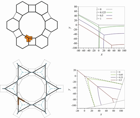
It is observed that a larger number of different n-sided polygonal grains introduced into the grain boundary network (squares, hexagons and dodecagons compared to octagons and squares) results in a more realistic evolution of the grain network. The initially equilateral hexagonal grains change their shape, due to the shrinkage of the initially quadratic grains, and due to the growth of the initially dodecagonal grains. It is worth noting that a change from a grain boundary network with 4-sided grains to one containing even more unstable 3-sided grains takes place during the minimization of grain boundary energy in the system. This topological change occurs without forming quadruple junctions in contrast to a further possible topological change described in reference [39].
(8)
In contrast to the shrinkage of regular n-sided grains with infinite triple junction mobilites, the shrinkage of regular n-sided grains with different triple junction mobilites results in a deformed n-sided grain, where the triple points do not migrate on straight lines, but follow complicated curved trajectories.
It has been already shown in previous works with various numerical methods that grains—even when a finite triple junction mobility is considered—will shrink for a number of edges n 5 and grow for n 7 , see e.g., references [2] and [44]. However, the calculations in this work demonstrated that all these calculations can be done by means of the vertex model developed in this work and the improved analytical relation β ( Λ ) is confirmed.

5. Conclusions and Outlook

The kinetics of grain growth are investigated by using distinct triple junction–grain boundary “unit cells” and the following conclusions can be drawn:
  • Both, the shrinkage of n-sided grains with n < 6 and the growth of grains with n > 6 is calculated depending on a finite triple junction mobility expressed by a dimensionless quantity Λ ¯ , independent of grain size. The numerical results agree very well with the modified analytical solution. It is confirmed that the area A of the grain containing triple junctions with high mobilities decreases linearly in time for n = 4. In case of triple junctions with low mobilities, the grain radius R shrinks linearly in time, except for the very last stage.
  • A triple junction-grain boundary “unit cell” is constructed in order to tessellate the plane by square shaped grains surrounded by hexagonal and dodecagonal grains. In contrast to the square-shaped grain surrounded by hexagons, an additional topological change is observed for this more realistic initial microstructure.
  • It is demonstrated that different triple junction mobilities have the potential to break an initially assumed symmetry of the grain topology completely, and thereby may lead to rather complex, strongly time dependent grain structure topologies.
It is expected that the theoretical and numerical tools developed in this work will help to interpret the dissipative processes of the growth kinetics when analyzing experimental results, e.g., in-situ movies of grain growth from laser scanning confocal microscopes. As an example, a low grain boundary mobility will be attributed to grain boundaries that are hindered in their motion by e.g., solute drag or particle pinning and different topological situations can be mimicked and thus grain boundary and triple junction mobilities can be estimated.

Author Contributions

Conceptualization, E.G.; methodology, E.G.; software, E.G., D.O. and J.S.; validation E.G., D.O. and J.S.; visualization, E.G.; writing—original draft preparation, E.G.; writing—review and editing, E.G. and J.S.

Funding

This research received no external funding.

Conflicts of Interest

The authors declare no conflict of interest.

References

  1. Han, J.; Kwiatkowski da Silva, A.; Ponge, D.; Raabe, D.; Lee, S.-M.; Lee, Y.-K.; Lee, S.-I.; Hwang, B. The effects of prior austenite grain boundaries and microstructural morphology on the impact toughness of intercritically annealed medium Mn steel. Acta Mater. 2017, 122, 199–206. [Google Scholar] [CrossRef]
  2. Mukherjee, M.; Prahl, U.; Bleck, W. Modelling the strain-induced precipitation kinetics of vanadium carbonitride during hot working of precipitation-hardened Ferritic–Pearlitic steels. Acta Mater. 2014, 71, 234–254. [Google Scholar] [CrossRef]
  3. Lu, Q.; Xu, W.; van der Zwaag, S. Designing new corrosion resistant ferritic heat resistant steel based on optimal solid solution strengthening and minimisation of undesirable microstructural components. Compd. Mater. Sci. 2014, 84, 198–205. [Google Scholar] [CrossRef]
  4. Schnitzer, R.; Radis, R.; Nöhrer, M.; Schober, M.; Hochfellner, R.; Zinner, S.; Povoden-Karadeniz, E.; Kozeschnik, E.; Leitner, H. Reverted austenite in PH 13-8 Mo maraging steels. Mater. Chem. Phys. 2010, 122, 138–145. [Google Scholar] [CrossRef]
  5. Haase, C.; Kühbach, M.; Barrales-Mora, L.A.; Wong, S.L.; Roters, F.; Molodov, D.A.; Gottstein, G. Recrystallization behavior of a high-manganese steel: Experiments and simulations. Acta Mater. 2015, 100, 155–168. [Google Scholar] [CrossRef]
  6. Wiessner, M.; Gamsjäger, E.; van der Zwaag, S.; Angerer, P. Effect of reverted austenite on tensile and impact strength in a martensitic stainless steel−An in-situ X-ray diffraction study. Mater. Sci. Eng. A 2017, 682, 117–125. [Google Scholar] [CrossRef]
  7. Bhadeshia, H.K.D.H. Recrystallisation of practical mechanically alloyed iron-base and nickel-base superalloys. Mater. Sci. Eng. A 1997, 223, 64–77. [Google Scholar] [CrossRef]
  8. Kolb, M.; Freund, L.P.; Fischer, F.; Povstugar, I.; Makineni, S.K.; Gault, B.; Raabe, D.; Müller, J.; Spiecker, E.; Neumeier, S.; Göken, M. On the grain boundary strengthening effect of boron in γ/γ’ Cobalt-base superalloys. Acta Mater. 2018, 145, 247–254. [Google Scholar] [CrossRef]
  9. Huber, D.; Werner, R.; Clemens, H.; Stockinger, M. Influence of process parameter variation during thermo-mechanical processing of an intermetallic β-stabilized γ-TiAl based alloy. Mater. Charact. 2015, 109, 116–121. [Google Scholar] [CrossRef]
  10. Danzer, R. On the relationship between ceramic strength and the requirements for mechanical design. J. Eur. Ceram. Soc. 2014, 34, 3435–3460. [Google Scholar] [CrossRef]
  11. Raabe, D. Computational Materials Science; Wiley-VCH: Weinheim, Germany, 1998; ISBN 3-527-29541-0. [Google Scholar]
  12. Raabe, D. Introduction of a scalable three-dimensional cellular automaton with a probabilistic switch rule for the discrete mesoscale simulation of recrystallization phenomena. Philos. Mag. A 1999, 79, 2339–2358. [Google Scholar] [CrossRef]
  13. Raghavan, S.; Sahay, S.S. Modeling the grain growth kinetics by cellular automaton. Mater. Sci. Eng. A 2007, 445–446, 203–209. [Google Scholar] [CrossRef]
  14. Anderson, M.P.; Srolovitz, D.J.; Grest, G.S.; Sahni, P.S. Computer simulation of grain growth–I. Kinetics. Acta Metall. 1984, 32, 783–791. [Google Scholar] [CrossRef]
  15. Rollett, A.D.; Srolovitz, D.J.; Anderson, M.P. Simulation and theory of abnormal grain growth–anisotropic grain boundary energies and mobilities. Acta Metall. 1989, 37, 1227–1240. [Google Scholar] [CrossRef]
  16. Ayad, A.; Wagner, F.; Rouag, N.; Rollett, A.D. Accelerated Potts model for grain growth–Application to an IF steel. Compd. Mater. Sci. 2013, 68, 189–197. [Google Scholar] [CrossRef]
  17. Zöllner, D. A Potts model for junction limited grain growth. Compd. Mater. Sci. 2011, 50, 2712–2719. [Google Scholar] [CrossRef]
  18. Chen, L.-Q. Computer simulation of the domain dynamics of a quenched system with a large number of nonconserved order parameters: The grain growth kinetics. Phys. Rev. B 1994, 50, 15752–15756. [Google Scholar] [CrossRef]
  19. Kamachali, R.D.; Steinbach, I. 3-D phase-field simulation of grain growth: Topological analysis versus mean-field approximations. Acta Mater. 2012, 60, 2719–2728. [Google Scholar] [CrossRef]
  20. Moelans, N.; Wendler, F.; Nestler, B. Comparative study of two phase-field models for grain growth. Compd. Mater. Sci. 2009, 46, 479–490. [Google Scholar] [CrossRef]
  21. Chang, K.; Chen, L.-Q.; Krill, C.E., III; Moelans, N. Effect of strong nonuniformity in grain boundary energy on 3-D grain growth behavior: A phase-field simulation study. Comput. Mater. Sci. 2017, 127, 67–77. [Google Scholar] [CrossRef]
  22. Lazar, E.A.; MacPherson, R.D.; Srolovitz, D.J. A more accurate two-dimensional grain growth algorithm. Acta Mater. 2010, 58, 364–372. [Google Scholar] [CrossRef]
  23. Mellbin, Y.; Hallberg, H.; Ristinmaa, M. An extended vertex and crystal plasticity framework for efficient multiscale modeling of polycrystalline materials. Int. J. Solids Struct. 2017, 125, 150–160. [Google Scholar] [CrossRef]
  24. Elsey, M.; Esedoglu, S.; Smereka, P. Simulations of anisotropic grain growth: Efficient algorithms and misorientation distributions. Acta Mater. 2013, 61, 2033–2043. [Google Scholar] [CrossRef] [Green Version]
  25. Bernacki, M.; Castel, Y.; Coupez, T.; Logé, R.E. Level set framework for the numerical modelling of primary recrystallization in polycrystalline materials. Scr. Mater. 2008, 58, 1129–1132. [Google Scholar] [CrossRef]
  26. Bernacki, M.; Logé, R.E.; Coupez, T. Level set framework for the finite-element modelling of recrystallization and grain growth in polycrystalline materials. Scr. Mater. 2011, 64, 525–528. [Google Scholar] [CrossRef]
  27. Fausty, J.; Bozzolo, N.; Munoz, D.P.; Bernacki, M. A novel level-set finite element formulation for grain growth with heterogeneous grain boundary energies. Mater. Des. 2018, 160, 578–590. [Google Scholar] [CrossRef]
  28. Hallberg, H.; Zhu, Y. Stability of grain boundary texture during isothermal grain growth in UO2 considering anisotropic grain boundary properties. J. Nucl. Mater. 2015, 465, 664–673. [Google Scholar] [CrossRef]
  29. Hillert, M. Analytical treatments of normal grain growth. Mater. Sci. Forum 1996, 204–206, 3–18. [Google Scholar] [CrossRef]
  30. Rios, P.R.; Glicksman, M.E. Topological and metrical analysis of normal grain growth in three dimensions. Acta Mater. 2007, 55, 1565–1571. [Google Scholar] [CrossRef]
  31. Fischer, F.D.; Svoboda, J.; Hackl, K. Modelling the kinetics of a triple junction. Acta Mater. 2012, 60, 4704–4711. [Google Scholar] [CrossRef]
  32. Barrales-Mora, L.A.; Gottstein, G.; Shvindlerman, L.S. Effect of a finite boundary junction mobility on the growth rate of grains in two-dimensional polycrystals. Acta Mater. 2012, 60, 546–555. [Google Scholar] [CrossRef]
  33. Johnson, A.E.; Voorhees, P.W. A phase-field model for grain growth with trijunction drag. Acta Mater. 2014, 67, 134–144. [Google Scholar] [CrossRef]
  34. Chang, K.; Moelans, N. Effect of grain boundary energy anisotropy on highly textured grain structures studied by phase-field simulations. Acta Mater. 2014, 64, 443–454. [Google Scholar] [CrossRef]
  35. Mießen, C.; Liesenjohann, M.; Barrales-Mora, L.A.; Shvindlerman, L.S.; Gottstein, G. An advanced level set approach to grain growth–Accounting for grain boundary anisotropy and finite triple junction mobility. Acta Mater. 2015, 99, 39–48. [Google Scholar] [CrossRef]
  36. Weygand, D.; Bréchet, Y.; Lépinoux, J. Mechanisms and Kinetics of Recrystallisation: A Two Dimensional Vertex Dynamics Simulation. Interface Sci. 2001, 9, 311–317. [Google Scholar] [CrossRef]
  37. Barrales-Mora, L.A.; Mohles, V.; Shvindlerman, L.S.; Gottstein, G. Effect of a finite quadruple junction mobility on grain microstructure evolution: Theory and simulation. Acta Mater. 2008, 56, 1151–1164. [Google Scholar] [CrossRef]
  38. Gottstein, G.; Ma, Y.; Shvindlerman, L.S. Triple junction motion and grain microstructure evolution. Acta Mater. 2005, 53, 1535–1544. [Google Scholar] [CrossRef]
  39. Barrales-Mora, L.A. 2D vertex modeling for the simulation of grain growth and related phenomena. Math. Comput. Simul 2010, 80, 1411–1427. [Google Scholar] [CrossRef]
  40. Streitenberger, P.; Zöllner, D. Triple junction controlled grain growth in two-dimensional polycrystals and thin films: Self-similar growth laws and grain size distributions. Acta Mater. 2014, 78, 114–124. [Google Scholar] [CrossRef]
  41. Ito, K. Two-dimensional simulation of the effect of the migration of triple junctions on crystallographic texture evolution through grain coarsening. Comput. Mat. Sci. 2012, 62, 117–125. [Google Scholar] [CrossRef]
  42. Novikov, V.Y. Impact of grain boundary junctions on grain growth in polycrystals with different grain sizes. Mater. Lett. 2008, 62, 2067–2069. [Google Scholar] [CrossRef]
  43. Zöllner, D.; Rios, P.R. Investigating the von Neumann-Mullins relation under triple junction dragging. Acta Mater. 2014, 70, 290–297. [Google Scholar] [CrossRef]
  44. Streitenberger, P.; Zöllner, D. von Neumann–Mullins-type evolution equations for triple and quadruple junction controlled grain growth. Scr. Mater. 2015, 109, 52–55. [Google Scholar] [CrossRef]
  45. Zöllner, D. Influence of the local topology on the von Neumann-Mullins-relation. Comput. Mater. Sci. 2017 137, 67–74. [CrossRef]
  46. Upmanyu, M.; Srolovitz, D.J.; Shvindlerman, L.S.; Gottstein, G. Triple Junction Mobility: A Molecular Dynamics Study. Interface Sci. 1999, 7, 307–319. [Google Scholar] [CrossRef]
  47. Holm, E.A.; Hassold, G.N.; Miodownik, M.A. On misorientation distribution evolution during anisotropic grain growth. Acta Mater. 2001, 49, 2981–2991. [Google Scholar] [CrossRef]
  48. Dillon, S.J.; Rohrer, G.S. Mechanism for the development of anisotropic grain boundary character distributions during normal grain growth. Acta Mater. 2009, 57, 1–7. [Google Scholar] [CrossRef] [Green Version]
  49. Mullins, W.W. Two dimensional motion of idealized grain boundaries. J. Appl. Phys. 1956, 27, 900–904. [Google Scholar] [CrossRef]
  50. Glicksman, M.E. Analysis of 3-D network structures. Phil. Mag. 2005, 85, 3–31. [Google Scholar] [CrossRef]
  51. Glicksman, M.E.; Rios, P.R. Minimal network partitions using average N-hedra. Phil. Mag. 2007, 87, 189–208. [Google Scholar] [CrossRef]
  52. Rios, P.R.; Glicksman, M.E. Topological theory of abnormal grain growth. Acta Mater. 2006, 54, 5313–5321. [Google Scholar] [CrossRef]
Figure 1. Initial arrangement of the grain boundaries (gb) 1, 2, and 3 at the triple point (tp): (a) The grain boundaries are fixed at their centers. These boundary conditions are strictly valid only for infinitely large grains. (b) The left and the upper half of gb 1 and gb 3 are confined by the upper left quarter of an initially quadratic grain. Symmetric boundary conditions are applied to the center of gb1 and gb3.
Metals 08 00977 g001
Figure 2. Sketch of the situation at the triple point: (a) The directions of the grain boundaries 1, 2, and 3 at the triple point are given by the unit vectors e _ 1 , e _ 2 , and e _ 3 , which comprise the angles α 1 , α 2 and α 3 with the x-axis. (b) The directions of the grain boundaries 1, 2, and 3 at the triple point are determined by the dihedral angle θ , the turning angle β and the angle α enclosed by grain boundary 1 at the triple point and the x-axis.
Metals 08 00977 g002
Figure 3. Schematic sketch of the forces at the triple junction, the net driving force P, the velocity vtp of the triple junction and the normal velocity vn of e.g., the grain boundary 1 at the triple point.
Metals 08 00977 g003
Figure 4. Grain sides i and vertices j are labelled in counterclockwise order, where β i j are the angles between the abscissa and the tangent to the i-th side at the j-th vertex (see also [49]).
Metals 08 00977 g004
Figure 5. Shrinking of the initially quadratic grain: (a) Case I: The centers of the grain boundaries are fixed; thus, an edge formation with angle ϑ can occur at this center. (b) Case II: The centers of the grain boundaries can move due to symmetric boundary conditions and the initially quadratic grain shrinks and eventually disappears.
Metals 08 00977 g005
Figure 6. Implementation of the symmetry boundary conditions at the centers of the grain boundaries.
Metals 08 00977 g006
Figure 7. Evolution of the grain boundaries and the triple junction with Λ ¯ = 2 determined numerically: (a) Case I: Boundary conditions for infinite grains. (b) Case II: Boundary conditions for finite grains.
Metals 08 00977 g007
Figure 8. Turning angle β as a function of Λ during the shrinkage of the 4-sided grain for different values of Λ ¯ . The direction of increasing time is indicated by arrows.
Metals 08 00977 g008
Figure 9. Rate of area change A ˙ versus time for a 4-sided grain with different values of A ¯ : (a) A very high value, Λ ¯ = 2 × 10 7 , and a medium value Λ ¯ = 2 , (b) A very small value Λ ¯ = 2 × 10 4 .
Metals 08 00977 g009
Figure 10. Dimensionless area plotted versus time t ¯ for different Λ ¯ -values. (a) Λ ¯ = 2 × 10 4 and Λ ¯ = 2 , (b) Λ ¯ = 1 and Λ ¯ = 0.2 .
Metals 08 00977 g010
Figure 11. R / R 0 . is plotted versus normalized time t ¯ for different Λ ¯ -values.
Metals 08 00977 g011
Figure 12. Evolution of the grain boundaries and the triple junction for the symmetry unit of an initially regular pentagon with Λ ¯ = 2 . (a) Case I, (b) Case II.
Metals 08 00977 g012
Figure 13. Evolution of the grain boundaries and the triple junction for the symmetry unit of an initially regular heptagon with Λ ¯ = 2 . (a) Case I, (b) Case II.
Metals 08 00977 g013
Figure 14. Evolution of the grain boundaries and the triple junction for the symmetry unit of an initially regular octagon with Λ ¯ = 2 . (a) Case I, (b) Case II.
Metals 08 00977 g014
Figure 15. Normalized area A / A 0 versus time t ¯ for different polygonal grains for Λ ¯ = 2 .
Metals 08 00977 g015
Figure 16. The arrangement is described by a “unit-cell” consisting of the highlighted triple point and the adjacent grain boundaries. (a) Grain arrangement A: Surface tessellated by alternating squares and octagons. (b) Grain arrangement B: Squares are surrounded by hexagons and dodecagons.
Metals 08 00977 g016
Figure 17. (a) Evolution of grain boundaries for arrangements A and B, respectively, with Λ ¯ = 2 (b) Normalized area versus time t ¯ for arrangements A and B, respectively, with Λ ¯ = 2 .
Metals 08 00977 g017
Figure 18. (a) Evolution of the grain boundary arrangement B. Earlier grain boundaries are represented by dotted lines, and the grain boundaries of the later dodecagon triangle grain boundary network are depicted as continuous lines. The “unit-cell” of the dodecagon-triangle network is highlighted. (b) Unit-cell of the dodecagon-triangle network and the shrinkage of the triangles with time.
Metals 08 00977 g018
Figure 19. Shrinkage of an initially quadratic grain in arrangement B with different mobilities at the triple junctions A, B, C and D.
Metals 08 00977 g019

