A Comprehensive CFD Model for Dual-Phase Brass Indirect Extrusion Based on Constitutive Laws: Assessment of Hot-Zone Formation and Failure Prognosis


Abstract
:1. Introduction
2. Numerical Model and Experimental Method
2.1. Model Desciption—Mathematical Formulation
2.1.1. Governing Equations
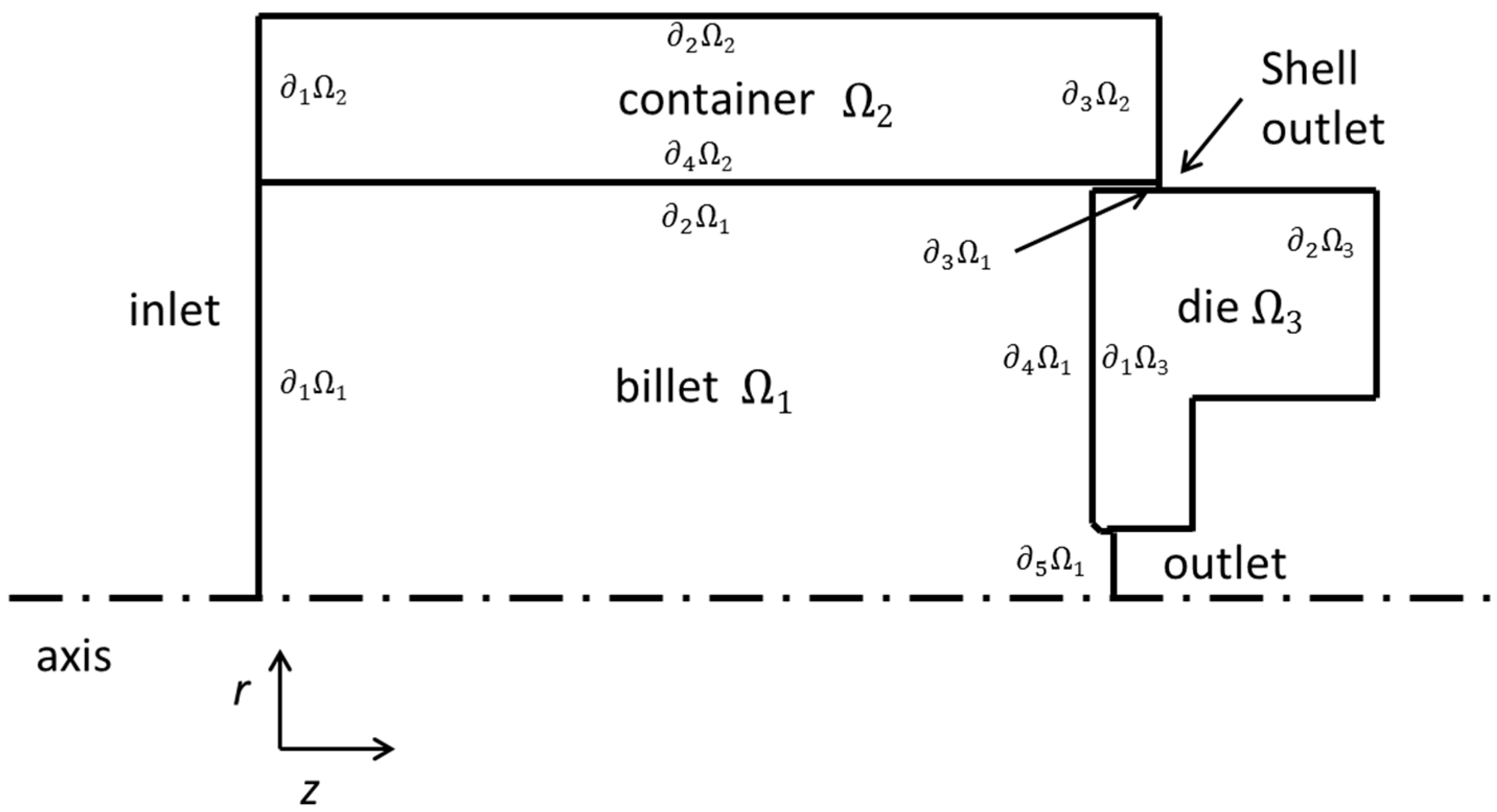
2.1.2. Solution Domain
2.1.3. Boundary Conditions
2.2. Plastic Stress
2.3. Model Assumptions
- Brass phases in the billet are distributed evenly (no spatial variation).
- There is no phase transition during the extrusion process, i.e., α-brass to β-brass or vice-versa.
- The temperature of the billet, far from the die (inlet temperature), is uniform.
- The process is in steady-state regime.
- Heat generation due to skin friction between the billet and the die is neglected. Heat is only produced due to the deformation of the billet.
- The alloying elements contribute only to the equivalent Zn.
- There is no friction between container and billet.
- The friction between billet and die is based on a simple hydrodynamic lubrication model.
2.4. Reduced Order Model
2.5. Process Parameters
2.5.1. Input Parameters
2.5.2. Output Parameters
2.6. Thermo-Physical Properties
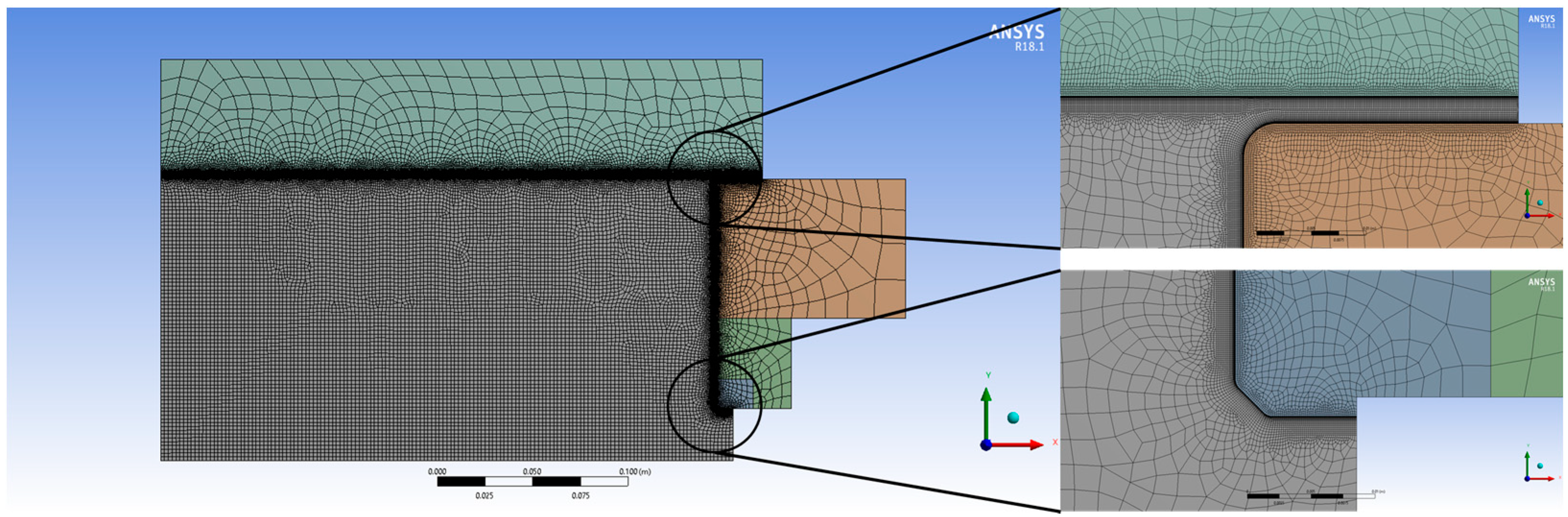
2.7. Mesh Sensitivity—Model Validity
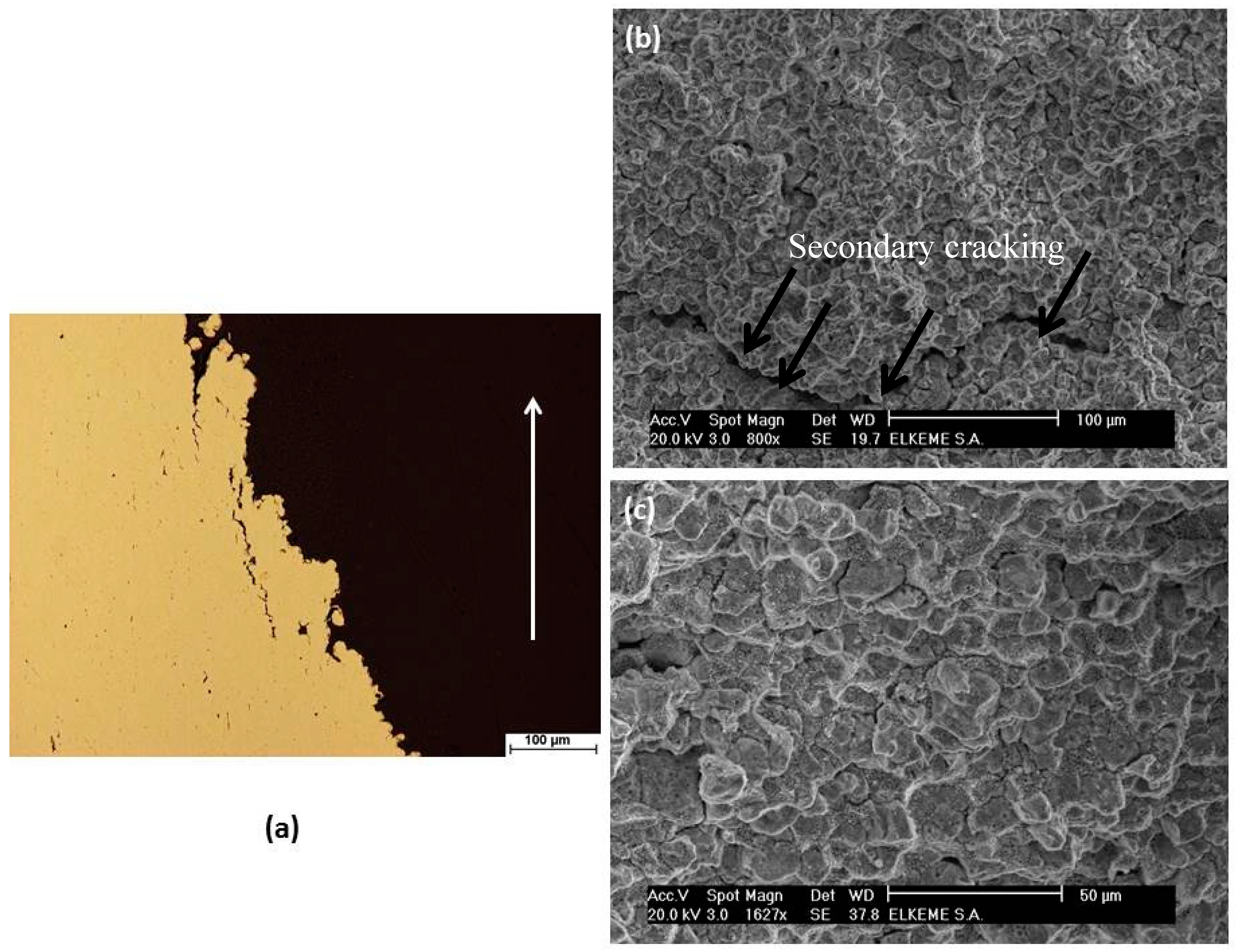
2.8. Experimental Characterization—Metallography and Fractography
3. Results and Discussion
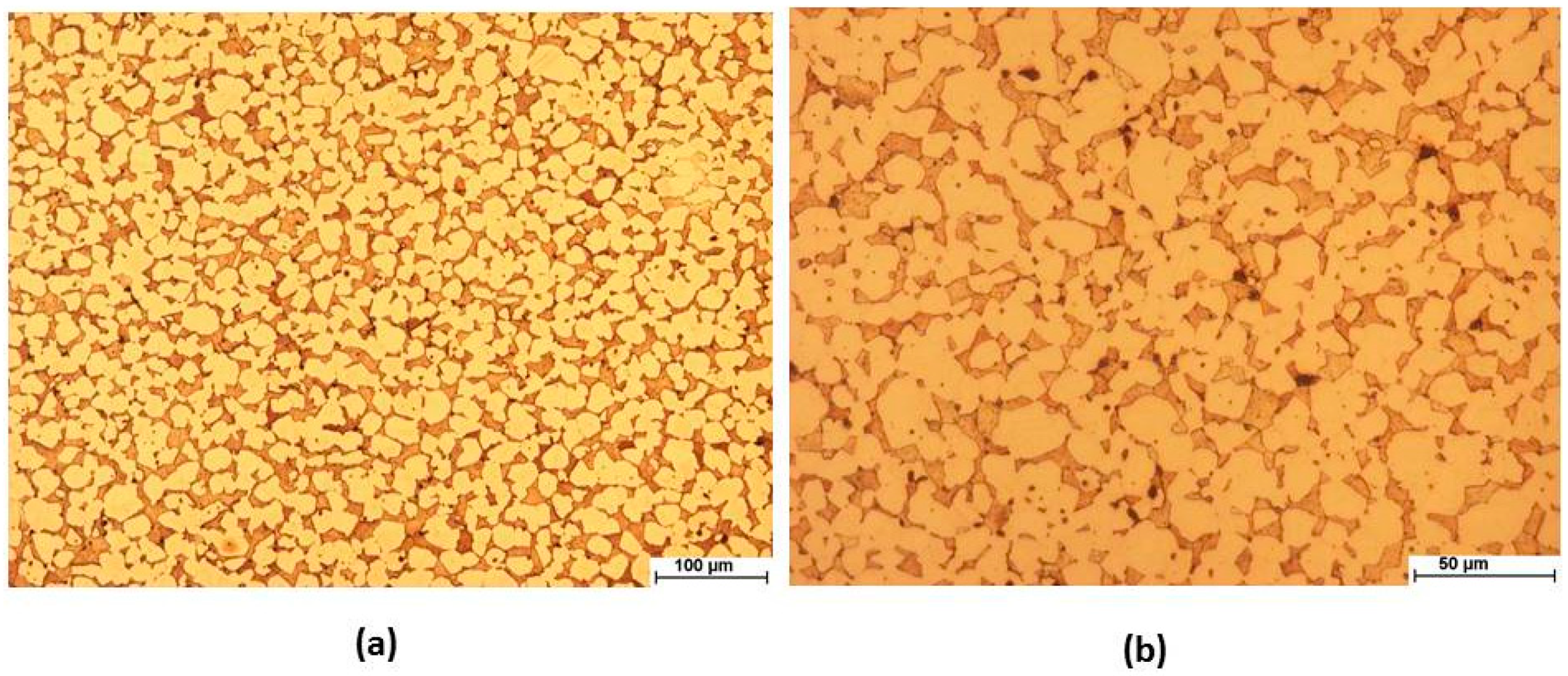
3.1. Microstructure
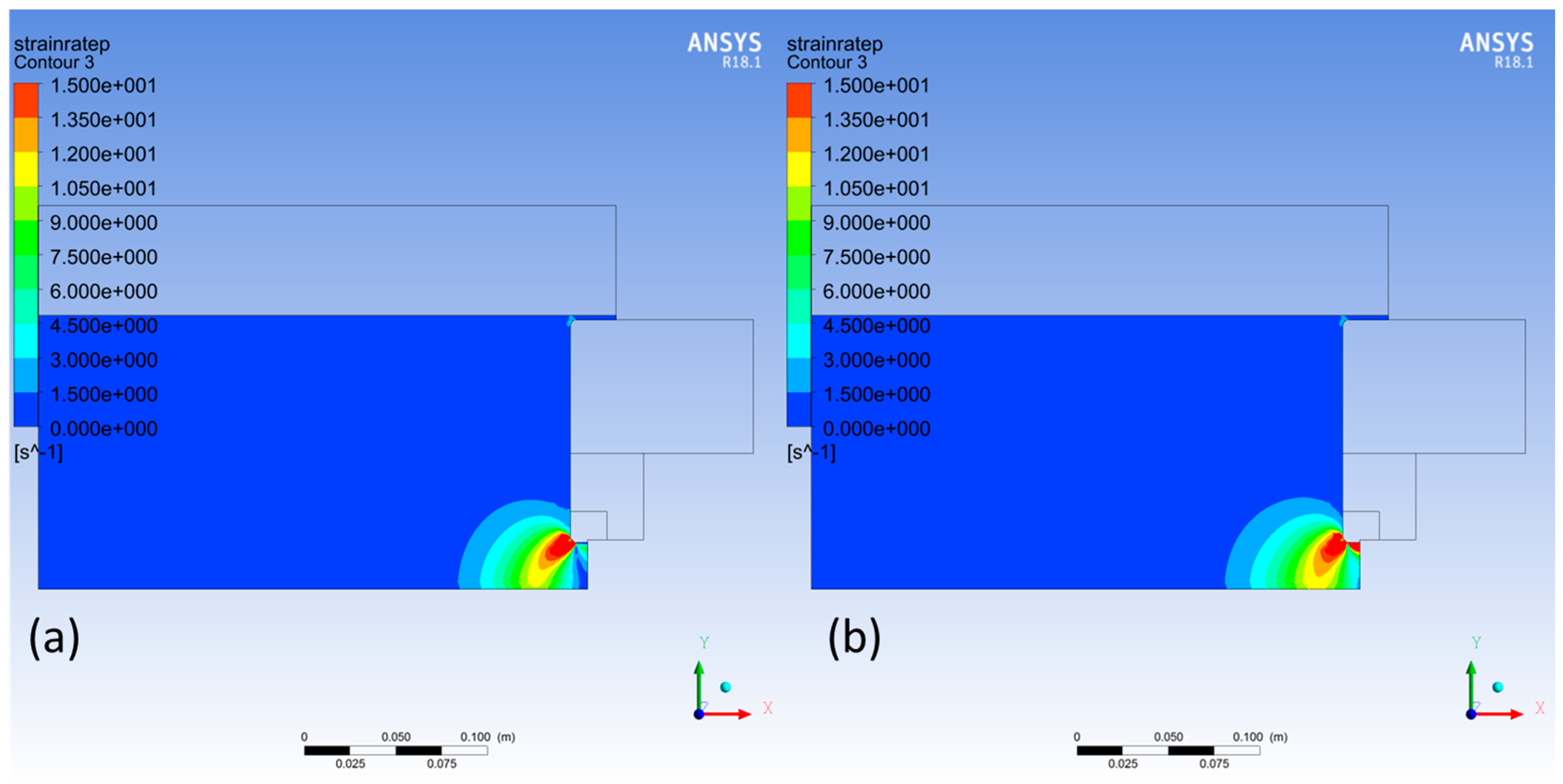
3.2. Equivalent Strain Rate
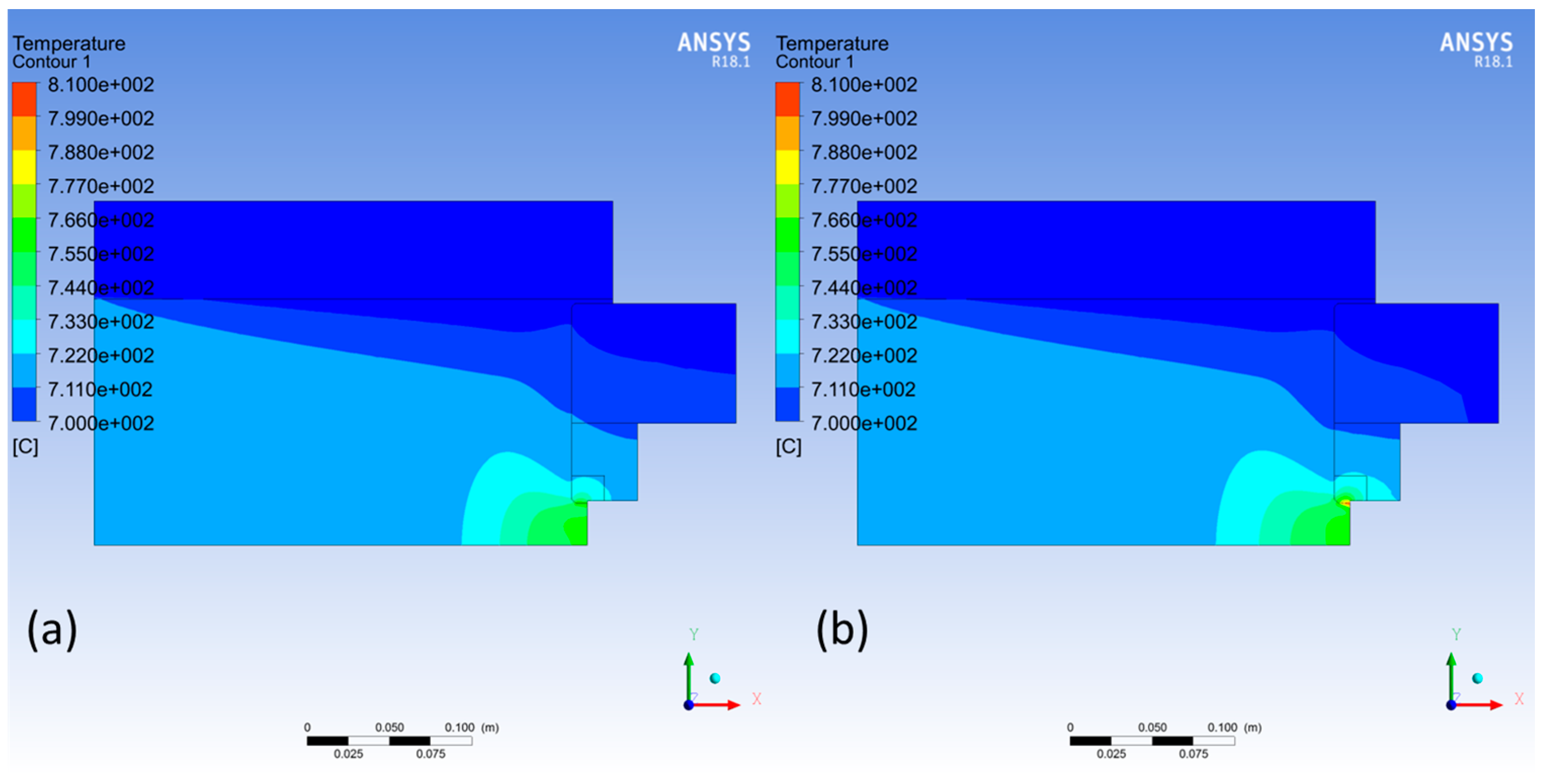
3.3. Temperature
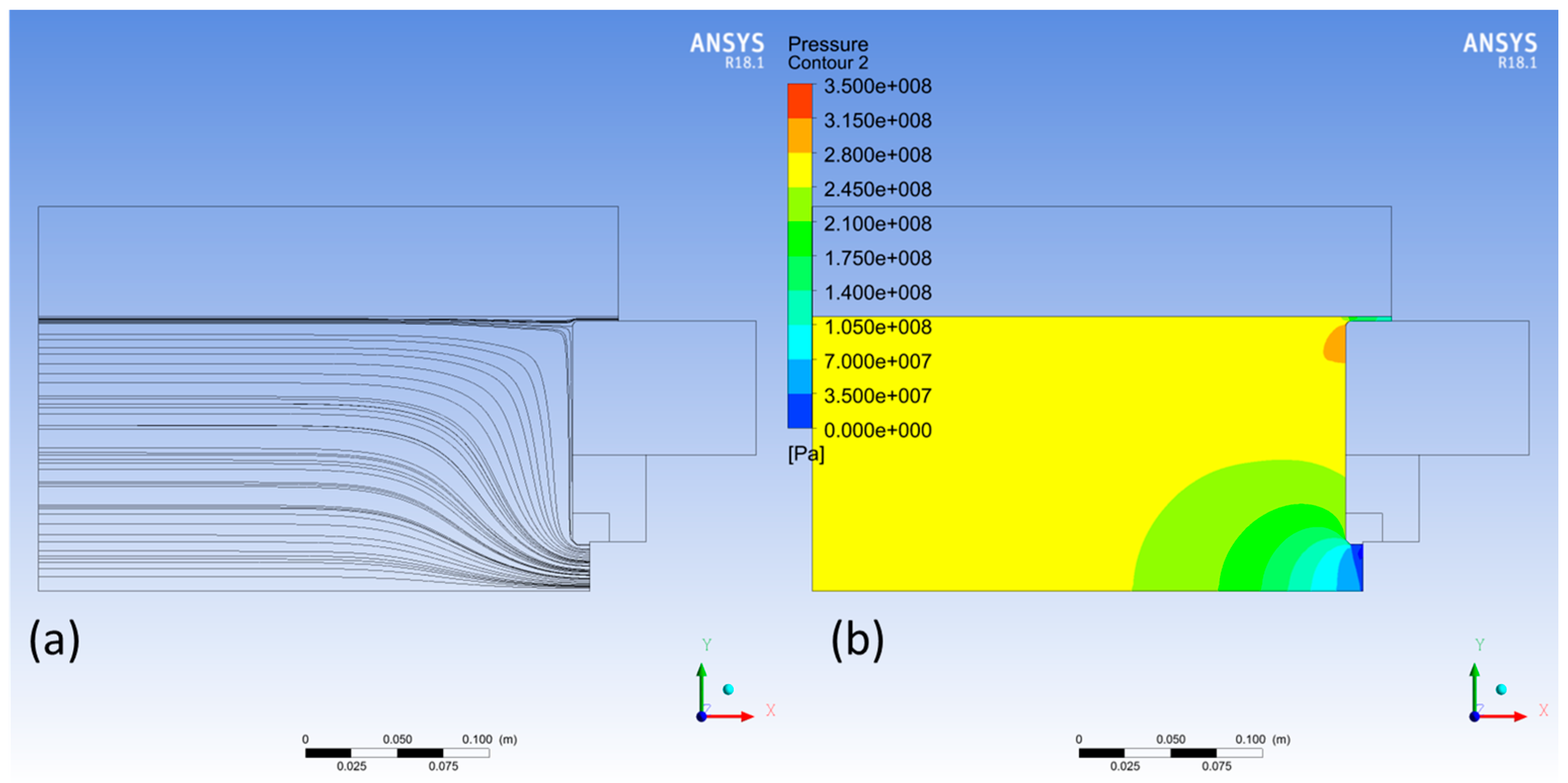
3.4. Pressure/Flow Profile
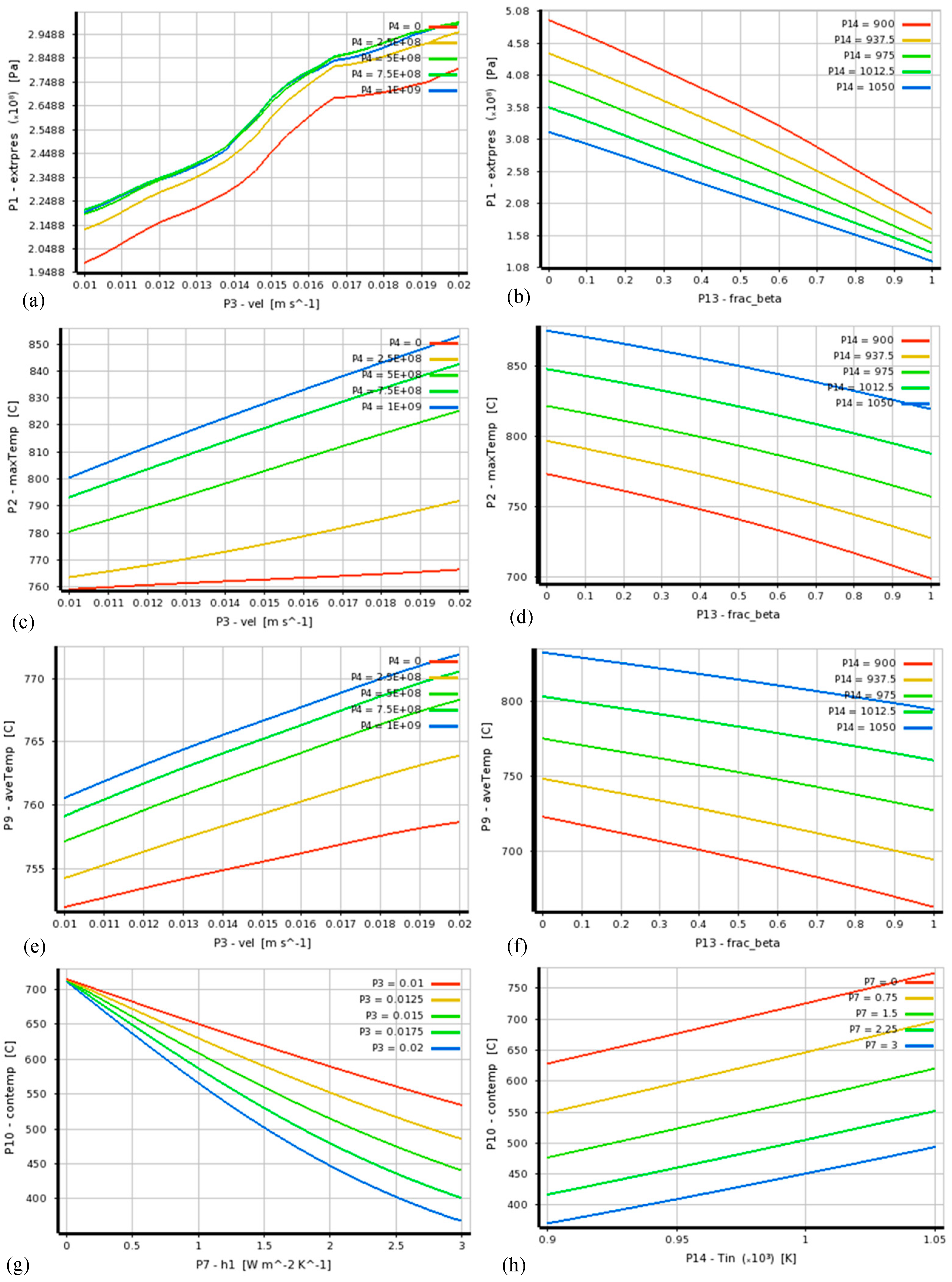
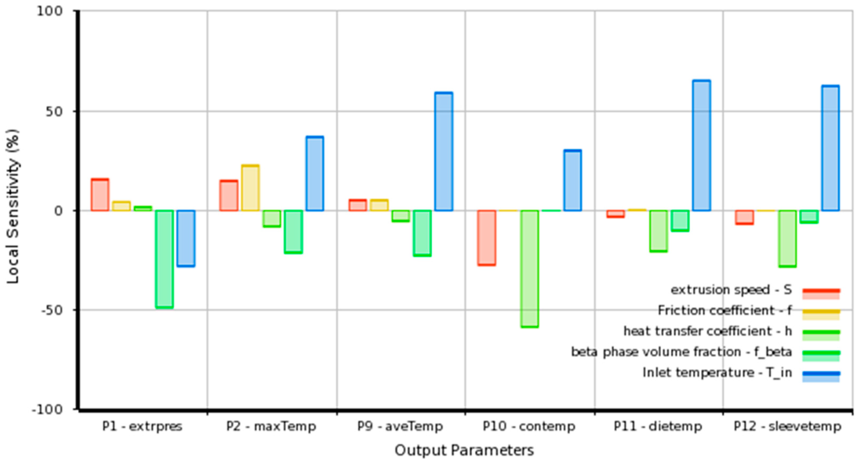
3.5. Sensitivity Analysis
3.6. Parametric Study
3.7. Phenomenological Aspects of Flow-Induced Extrusion Failures
4. Conclusions
Author Contributions
Funding
Acknowledgments
Conflicts of Interest
Appendix A. Relationship between Plastic Stress and Viscosity
References
- Kuyucak, S.; Sahoo, M. A review of the machinability of copper-base alloys. Can. Met. Q. 1996, 35, 1–15. [Google Scholar] [CrossRef]
- Pantazopoulos, G. Leaded brass rods C38500 for automatic machining operations. J. Mater. Eng. Perform. 2002, 11, 402–407. [Google Scholar] [CrossRef]
- Gane, N. The effect of lead on the friction and machining of brass. Philos. Mag. 1981, 43, 545–566. [Google Scholar] [CrossRef]
- Garcia, P.; Rivera, S.; Palacios, M.; Belzunce, J. Comparative study of the parameters influencing the machinability of leaded brasses. Eng. Fail. Anal. 2010, 17, 771–776. [Google Scholar] [CrossRef]
- Pantazopoulos, G.; Toulfatzis, A. Fracture modes and mechanical characteristics of machinable brass rods. Met. Microstruct. Anal. 2012, 1, 106–114. [Google Scholar] [CrossRef]
- Toulfatzis, A.; Pantazopoulos, G.; Paipetis, A. Fracture behavior and characterization of lead-free brass alloys for machining applications. J. Mater. Eng. Perform. 2014, 23, 3193–3206. [Google Scholar] [CrossRef]
- Toulfatzis, A.; Pantazopoulos, G.; Paipetis, A. Microstructure and properties of lead-free brasses using post-processing heat treatment cycles. Mater. Sci. Technol. 2016, 32, 1771–1781. [Google Scholar] [CrossRef]
- Toulfatzis, A.; Pantazopoulos, G.; Paipetis, A. Fracture mechanics properties and failure mechanisms of environmental-friendly brass alloys under impact, cyclic and monotonic loading conditions. Eng. Fail. Anal. 2018, 90, 497–517. [Google Scholar] [CrossRef]
- Toulfatzis, A.; Pantazopoulos, G.; David, C.; Sagris, D.; Paipetis, A. Final heat treatment as a possible solution for the improvement of machinability of lead-free brass alloys. Metals 2018, 8, 575. [Google Scholar] [CrossRef]
- Toulfatzis, A.I.; Pantazopoulos, G.A.; Besseris, G.J.; Paipetis, A.S. Machinability evaluation and screening of leaded and lead-free brasses using a non-linear robust multifactorial profiler. Int. J. Adv. Manuf. Technol. 2016, 86, 3241–3254. [Google Scholar] [CrossRef]
- Toulfatzis, A.; Pantazopoulos, G.; David, C.; Sagris, D.; Paipetis, A. Machinability of eco-friendly lead-free brass alloys: Cutting-force and surface-roughness optimization. Metals 2018, 8, 250. [Google Scholar] [CrossRef]
- Pantazopoulos, G. A review of defects and failures in brass rods and related components. Pract. Fail. Anal. 2003, 3, 14–22. [Google Scholar] [CrossRef]
- Valberg, H.S. Applied Metal Forming—Including FEM Analysis; Cambridge University Press: Cambridge, UK, 2010. [Google Scholar]
- Bozzi, S.; Vedani, M.; Lotti, D.; Passoni, G. Extrusion of aluminium hollow pipes: Seam weld quality assessment via numerical simulation. Met. Sci. Technol. 2009, 27, 20–29. [Google Scholar]
- Mitsoulis, E. Flows of viscoplastic materials: Models and computations. Rheol. Rev. 2007, 2007, 135–178. [Google Scholar]
- Bird, R.B.; Stewart, W.E.; Lightfoot, E.N. Transport Phenomena, 2nd ed.; Wiley: Hoboken, NJ, USA, 2002. [Google Scholar]
- Schmitter, E.D. Modelling massive forming processes with thermally coupled fluid dynamics. In Proceedings of the COMSOL Multiphysics User’s Conference, Bostion, MA, USA, 23–25 October 2005. [Google Scholar]
- Spigarelli, S.; El Mehtedi, M.; Cabibbo, M.; Gabrielli, F.; Ciccarelli, D. High temperature processing of brass: Constitutive analysis of hot working of Cu–Zn alloys. Mater. Sci. Eng. A 2014, 615, 331–339. [Google Scholar] [CrossRef]
- Spigarelli, S.; El Mehtedi, M.; Cabibbo, M. Characterization of Hot Deformation of CW602N Brass. Acta Phys. Pol. 2015, 128, 726–729. [Google Scholar] [CrossRef]
- Pernis, R.; Kasala, J.; Boruta, J. High temperature plastic deformation of CuZn30 brass—Calculation of the activation energy. Kov. Mater. 2010, 48, 41–46. [Google Scholar] [CrossRef]
- Yang, L.-C.; Pan, Y.-T.; Chen, I.-G.; Lin, D.-Y. Constitutive relationship modeling and characterization of flow behavior under hot working for Fe–Cr–Ni–W–Cu–Co super-austenitic stainless steel. Metals 2015, 5, 1717–1731. [Google Scholar] [CrossRef]
- Orman, L. Tensile Behaviour of Alpha Brasses at Elevated Temperature. Master’s Thesis, Department Metallurgical Engineering, University of British Columbia, Salt Lake City, UT, USA, 1982. [Google Scholar]
- Gulyaev, A.P. Physical Metallurgy; MIR Publishers: Moscow, Russia, 1980; Volume 2. [Google Scholar]
- Box, G.E.P.; Wilson, K.B. On the experimental attainment of optimum conditions (with discussion). J. R. Stat. Soc. Ser. B 1951, 13, 1–45. [Google Scholar]
- Ansys Inc. DesignXplorer User’s Guide; Ansys Inc.: Canonsburg, PA, USA, 2017. [Google Scholar]
- Fluent, A. Theory Guide; Ansys Inc.: Canonsburg, PA, USA, 2017. [Google Scholar]
- Valencia, J.J.; Quested, P.N. Thermophysical properties. In ASM Handbook; ASM International: Novelty, OH, USA, 2008; Volume 15, pp. 468–481. [Google Scholar]
- Pantazopoulos, G.; Vazdirvanidis, A. Characterization of microstructural aspects of machinable α-β phase brass. Microsc. Anal. 2008, 22, 13–16. [Google Scholar]
- Laue, K.; Stenger, H. Extrusion—Processes Machinery, Tooling; ASM International: Novelty, OH, USA, 1981. [Google Scholar]
- Higgins, R. Engineering Metallurgy-Applied Physical Metallurgy, 6th ed.; Edward Arnold: London, UK, 1998. [Google Scholar]
- Pernis, R.; Kasala, J.; Pernis, I. Surface defects of brass bars. In Proceedings of the International Conference “Metal 2011”, Brno, Czech Republic, 18–20 May 2011. [Google Scholar]
- Pantazopoulos, G.; Vazdirvanidis, A. Failure analysis of a fractured leaded-brass (CuZn39Pb3) extruded hexagonal rod. J. Fail. Anal. Prev. 2008, 8, 218–222. [Google Scholar] [CrossRef]
- Pantazopoulos, G.; Vazdirvanidis, A. Fracture analysis and embrittlement phenomena of machined brass components. Procedia Struct. Integr. 2017, 5, 476–483. [Google Scholar] [CrossRef]
- Lynch, S.P. Failures of structures and components by metal-induced embrittlement. J. Fail. Anal. Prev. 2008, 8, 259–274. [Google Scholar] [CrossRef]
- Sugimoto, M.; Igaki, H.; Saito, K. Equivalent stress (rate) and equivalent strain rate for work-hardening materials: Theory of anisotropic plasticity based on maximum shear stress hypothesis. Trans. Jpn. Soc. Mech. Eng. 1973, 39, 1164–1174. [Google Scholar] [CrossRef]


| Brass | Q (J/mol) | A (s−1) | n (Dimensionless) | a (MPa−1) |
|---|---|---|---|---|
| CuZn36 | 157,000 | 6.60 × 10⁹ | 4.5 | 6.58 × 10⁻³ |
| CuZn44 | 92,000 | 1.44 × 10⁷ | 3.0 | 9.21 × 10⁻³ |
| Input Parameter | Notation | Alternate Notation (Reduced Order Model) | Units |
|---|---|---|---|
| Extrusion speed | S | P3 | m/s |
| Friction factor | f | P4 | Ns/m3 |
| Heat transfer coefficient on the liner outer walls | h | P7 | W/(m2 K) |
| β-phase volume fraction | P13 | dimensionless | |
| Inlet (initial) temperature of the billet | Tin | P14 | K |
| Output Parameter | Notation | Alternate Notation (Reduced Order Model) | Units |
|---|---|---|---|
| Extrusion pressure | extrpress | P1 | Pa |
| Maximum temperature (hot spots—see Section 3.2) | maxTemp | P2 | °C |
| Average temperature of the extruded product | aveTemp | P9 | °C |
| Average temperature of the container liner | contemp | P10 | °C |
| Average temperature of the die | dietemp | P11 | °C |
| Average temperature of the brass shell | sleevetemp | P12 | °C |
| Property | Brass—CW626N | Steel (Die & Container) |
|---|---|---|
| Density (kg/m3) | 8500 | 8030 * |
| Specific heat (J/(kg·K)) | 355 + 0.136T [27] | 502.48 * |
| Thermal conductivity (W/(m·K)) | 140.62 + 0.011214T [27] | 25 ** |
| Viscosity (Pa·s) | Equation (3) | N/A |
| Billet Number | Inlet Temperature (°C) | Extrusion Speed (cm/s) | Hydraulic Pressure (bar) | Calculated Hydraulic Pressure (bar) |
|---|---|---|---|---|
| 1 | 713.5 | 1.45 | 155 | 154.2 |
| 2 | 716.0 | 1.45 | 150 | 152.9 |
| 3 | 717.0 | 1.50 | 155 | 157.6 |
| 4 | 721.5 | 1.45 | 150 | 150.1 |
| Input parameter | Interval | Units |
|---|---|---|
| S | [0.01, 0.02] | m/s |
| f | [0, 109] | Ns/m3 |
| h | [0, 3] | W/(m2 K) |
| fβ | [0, 1] | dimensionless |
| Tin | [900, 1050] | K |
© 2018 by the authors. Licensee MDPI, Basel, Switzerland. This article is an open access article distributed under the terms and conditions of the Creative Commons Attribution (CC BY) license (http://creativecommons.org/licenses/by/4.0/).
Share and Cite
Pashos, G.; Pantazopoulos, G.A.; Contopoulos, I. A Comprehensive CFD Model for Dual-Phase Brass Indirect Extrusion Based on Constitutive Laws: Assessment of Hot-Zone Formation and Failure Prognosis. Metals 2018, 8, 1043. https://doi.org/10.3390/met8121043
Pashos G, Pantazopoulos GA, Contopoulos I. A Comprehensive CFD Model for Dual-Phase Brass Indirect Extrusion Based on Constitutive Laws: Assessment of Hot-Zone Formation and Failure Prognosis. Metals. 2018; 8(12):1043. https://doi.org/10.3390/met8121043
Chicago/Turabian StylePashos, George, George A. Pantazopoulos, and Ioannis Contopoulos. 2018. "A Comprehensive CFD Model for Dual-Phase Brass Indirect Extrusion Based on Constitutive Laws: Assessment of Hot-Zone Formation and Failure Prognosis" Metals 8, no. 12: 1043. https://doi.org/10.3390/met8121043
APA StylePashos, G., Pantazopoulos, G. A., & Contopoulos, I. (2018). A Comprehensive CFD Model for Dual-Phase Brass Indirect Extrusion Based on Constitutive Laws: Assessment of Hot-Zone Formation and Failure Prognosis. Metals, 8(12), 1043. https://doi.org/10.3390/met8121043