Abstract
Aluminum powders with different concentrations of TiC ceramic particles were applied to an AZ31B magnesium alloy by laser cladding. Due to differences in coefficients of thermal expansion, the distribution of TiC ceramic particles in the cladding layer was not uniform. The results show that the degree of TiC ceramic particle agglomeration in the cladding layer increases with increasing TiC content. The phases of cladding metal mainly consisted of Al, γ-Al12Mg17, β-Al3Mg2, and TiC. The γ-Al12Mg17 phase mainly distributed to the bottom of the cladding layer, and the β-Al3Mg2 phase distributed to the middle and surface areas. The existence of the γ-Al12Mg17 phase enhanced the hardness of the fusion zone. The microhardness of the cladding layer increased with increasing TiC ceramic particle content. An appropriate TiC content improved the wear resistance of the cladding layer. When the TiC content was excessive, the agglomeration behavior of TiC ceramic particles strongly affected the wear resistance of the coatings.
1. Introduction
Laser cladding technology can effectively improve the surface properties of magnesium or magnesium alloy, which expands the application scope of magnesium and magnesium alloy in industry [1,2,3]. To fabricate a high-quality coating with good metallurgical bonding with the substrate, the cladding layer should have good physical properties that match those of the magnesium alloy substrate [4,5]. Aluminum has physical properties similar to those of magnesium alloy, and its corrosion resistance and toughness are excellent, but the hardness and wear resistance are lower [6,7,8]. Ceramic particles have higher hardness, wear resistance, and corrosion resistance [9]. Therefore, ceramic particles are usually added into aluminum coating powder to fabricate a ceramic-metal composite cladding layer on the surface of magnesium alloy.
Riquelme et al. [10] fabricated Al/SiCp composite coatings on the surface of ZE41 magnesium alloys and the influence of laser cladding process parameters on the cladding geometry, dilution rate, and mechanical properties was investigated systematically. Sun et al. [11] applied a layer of Al-Si+SiC composite coating to the surface of AZ91D magnesium alloy and studied the changes of its surface properties. The existence of SiC ceramic particles improved the wear resistance of the cladding layer. Zhu et al. [12] used laser cladding technology to fabricate Al-Cu coatings on AZ91D magnesium alloy. The elemental Al and Cu formed intermetallic compounds in the coating. The hardness and wear resistance of the composite coating were improved significantly.
An Al-based composite coating, with added ceramic particles or synthetic hard phases, can enhance the surface properties of magnesium alloy. Scholars studied many factors, such as parameters and rare-earth elements, that influence the micro-structure and properties of an Al-based cladding layer [13]. However, research on the effect of the distribution and morphology of ceramic particles on composite coating properties is rare. The cause of morphology and distribution is also rarely investigated.
In the current study, aluminum powder with different concentrations of TiC ceramic particles was applied to an AZ31B magnesium alloy. Primarily, we studied the morphology and distribution of the TiC ceramic particles. The effect of morphology and distribution of ceramic particles on the micro-structure and properties of coatings was also analyzed in detail.
2. Materials and Methods
2.1. Materials
The chemical composition of AZ31B magnesium alloy is Al 2.9 wt%, Si 0.08 wt%, Ca 0.04 wt%, Zn 1.1 wt%, Mn 0.6 wt%, Fe 0.003 wt%, Cu 0.01 wt%, Ni 0.001 wt%, and Mg for the balance. The dimensions of the substrate were 100 × 80 × 7 mm. The chemical composition of specifically designed coating powders is Al+xTiC (x = 5 wt%, 10 wt%, 15 wt%, and 20 wt%). The TiC content started at 5% because the effect of pure aluminum powder on magnesium alloy coating has been studied before [14]. In addition, if the TiC content is less than 5%, it is difficult to mix the TiC evenly in the coating powders, and the effect is not the best when the TiC content is 5%. In addition, we also found that when the content of TiC is more than 20%, TiC ceramic particles will fall off from the cladding metal, and the formation of the cladding layer is very poor. The average sizes of Al and TiC ceramic particles were about 50 μm and 10 μm, respectively. The shape and size of powder particles is shown in Figure 1, and the purity level was all 99–99.5%.
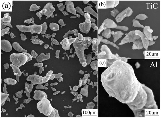
Figure 1.
(a) Shape of powder particles; (b) TiC particle shapes; (c) Al particle shapes.
The oxide film on the surface of AZ31B magnesium alloy was polished mechanically and then cleaned with acetone to remove organic matter [15]. The coating powders were mixed uniformly with alcohol to coat the surface of work-piece to a thickness of about 1.0 mm. The coating powders were welded by a JK2003SM Nd:YAG laser (GSI, Swift Valley, United Kingdom). The laser power, scanning velocity, and spot diameter were 1200 W, 8 mm/s, and 3 mm, respectively. Argon was used to protect the cladding layer from oxidation, and the argon flow rate was 25 mL/min. To investigate the tribological behavior of the cladding layer, three superimposed tracks were welded, and the overlap ratio was 30%.
2.2. Microstructural Characterization
After the laser cladding, specimens were cut from transverse cross-sections of the composite coating. Metallographic samples were mounted, polished, and etched by nitrohydrochloric acid (the ratio of nitric acid and hydrochloric acid was 1:3) in line with standard procedures. The distribution and morphology of the TiC ceramic in the composite coating were characterized by a Hitachi S4800 (HITACHI, Tokyo, Japan) scanning electron microscope (SEM). The phase of the polished coating was identified by a D8 Advance X-ray (BRUKEY, Tübingen, Germany) diffractometer (XRD, 40 kV, 40 mA, Cu Kα radiation, and scanning speed of 4°/min).
2.3. Evaluation of Mechanical Properties
A MHV2000 (Shanghai Metallographic Equipment Co., Ltd, Shanghai, China) digital microhardness tester with a 200 g load and 20 s dwell time was used to measure the microhardness from the alloy coating surface to the substrate.
Friction wear specimens measuring 25 × 7 × 7 mm were cut from the coatings, and under each variable, we took 5 specimens. The tribological behavior of the cladding layer was tested on a MM-200 (Jinan Liangong Testing Technology Co., Ltd., Jinan, China) dry sliding wear tester. The friction wear specimens were cleaned by acetone before the experiment. The material of the tribological pair was GCr15, the outer diameter was Φ40 mm, and the thickness was 10 mm. Wear specimens were subjected to sliding for 20 min under a load of 49 N and 200 rev/min. After the wear test, the wear volumes were calculated by Equation (1) [16]:
where B is the width of the wear scar (mm), L is the length of the wear scar (mm), and R is the outer radius of the wear ring (i.e., Φ50 mm).
The length and width of wear scar were measured five times, and the average values were substituted into Equation (1). The morphology and element distribution of the worn surface were studied with an S4800 SEM.
3. Results and Discussion
3.1. Micro-Structure of Composite Coating
The TiC/Al composite coating and AZ31B magnesium alloy substrate had good adhesion. As shown in Figure 2, the interface did not have any defects, such as porosity and slag.
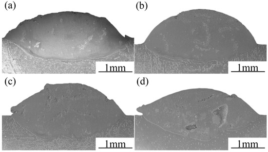
Figure 2.
Cross-section of the composite coatings: (a) Al+5wt.%TiC; (b) Al+10wt.%TiC; (c) Al+15wt.%TiC; (d) Al+20wt.%TiC.
The distribution of TiC ceramic particles in the cladding layer was very inhomogeneous. TiC ceramic particles in the cladding layer produced an agglomeration phenomenon, and the agglomeration become more pronounced as the content of ceramic particles increased. In the process of preparing metallographic specimens, larger ceramic particles fell off from the coating, as shown in Figure 2d.
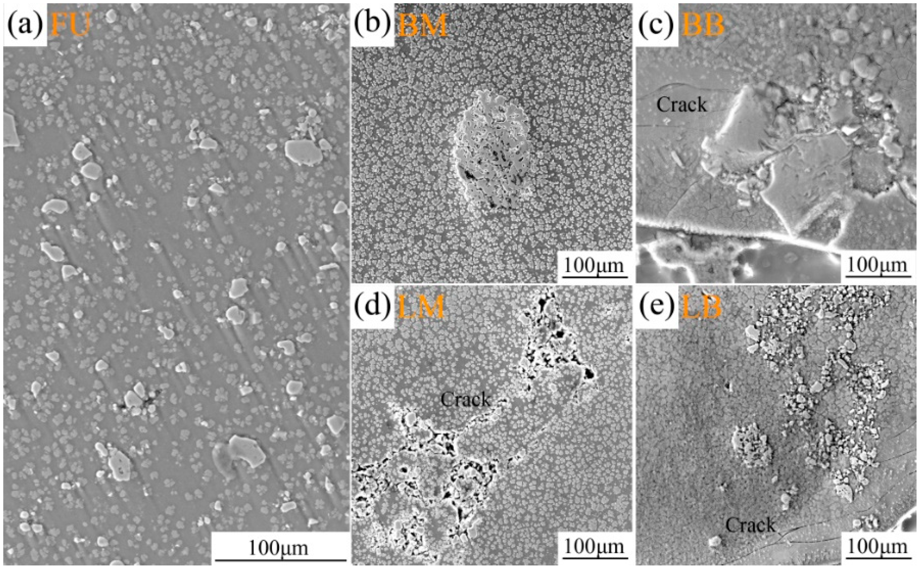
Figure 3 shows the morphology of TiC ceramic particles in the cladding layer. The content of the TiC is 5%. Five types of morphology were observed. Type FU (Fine Uniform in the cladding) was characterized by fine ceramic particles that were uniformly distributed in the coating, as shown in Figure 3a. A small number of fused particles generated big size particles distributed in the middle cladding layer, named type BM (Big size particles in the middle of cladding), as shown in Figure 3b. In type BB (Big size particles in bottom of the cladding), particles were distributed in the bottom, as shown in Figure 3c. A large amount of unfused ceramic particles gathered to form large area particles. Finally, two types of LM (Large area particles in middle of cladding) and LB (Large area particles in bottom of cladding) were defined on the basis of particle pattern, as shown in Figure 3d,e.
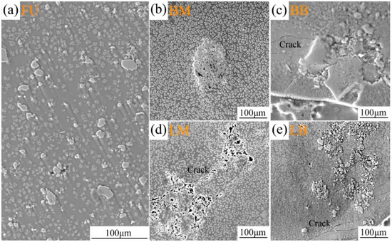
Figure 3.
Morphology and distribution of 5% TiC ceramic particles in the cladding layer: (a) Type FU, uniform distribution in the coating; (b) Type BM, distribution in the middle cladding layer; (c) Type BB, distribution in the bottom layer; (d) Type LM; (e) Type LB.
In types BB and LB, stress in the bottom of coatings produced obvious cracks in the direction along the fusion line. No radial cracks were observed around particles in type LM, but cracks were generated and propagated into the interior of particles. AZ31B magnesium alloy and particles in type BM have good metallurgical bonding with the matrix and no radical cracks were found around particles. In types BB, LM, and LB, ceramic particles may be the source of cracks because they have irregular shapes. In addition, residual stress existed in the cladding layer and bond zone after the laser cladding process. As a result, the irregular ceramic particles in these locations could form cracks that spread to the metal matrix.
Ceramic particles display agglomeration phenomena mainly due to two reasons. The first reason is the large difference in physical properties between the ceramic particles and cladding layer metal. The thermal expansion coefficients of elemental Fe, Cr, Ni, Al, and Mg are 12.2 × 10⁻⁶ K, 6.2 × 10⁻⁶ K, 13.0 × 10⁻⁶ K, 23.2 × 10⁻⁶ K, and 26.0 × 10⁻⁶ K, respectively. In contrast, the TiC ceramic particle has an expansion coefficient of 7.4 × 10⁻⁶ K. The thermal expansion coefficients between the elements in an Fe-based coating, Fe, Cr, and Ni, and TiC ceramic are similar. However, the values for Al and Mg are about three or four times larger than that of TiC. This large difference in thermal expansion coefficient could severely affect the metallurgical bonding between the ceramic particles and cladding layer metal; many defects will be produced and destroy the properties of the coating. Hence, the difference of physical properties is the main reason for the agglomeration phenomenon in the ceramic-metal coating [17,18].
The second reason for agglomeration is that the granularity of ceramic particles is too small [19]. In previous research [20], the same size TiC ceramic particles (10 μm) were added to an Fe-based powder (50 μm). The ceramic particles did not generate the agglomeration phenomenon in the cladding layer. However, in this study, TiC ceramic particles display a significant agglomeration behavior in the Al-based coating and are accompanied with many cracks. As a result, the effect of ceramic particle size could be ignored. The Fe, Cr, and Ni are the three main elements in the Fe-based coating, but the Al-based coating mainly contains Al and Mg, where the Mg can be obtained from the AZ31B magnesium alloy via dilution.
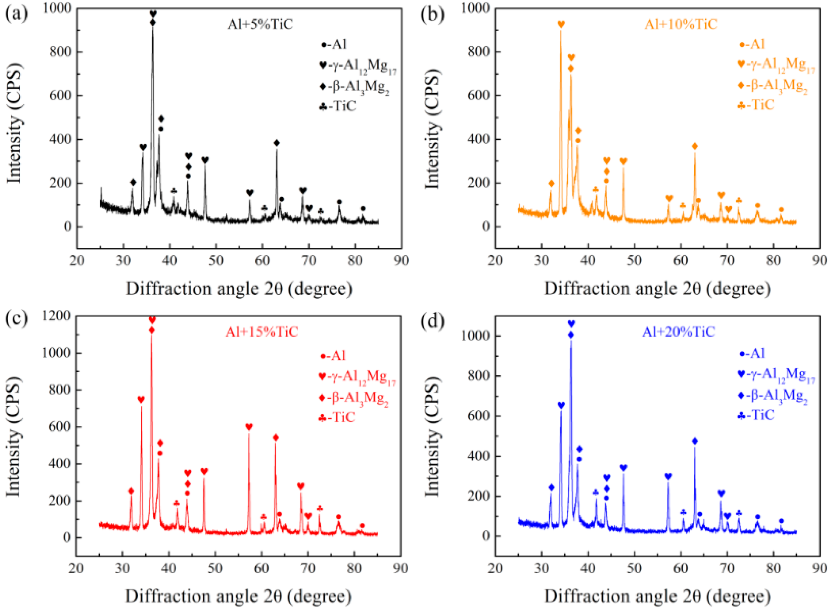
The detection zone size of the XRD is about 2 × 2 mm, and it not include the agglomeration area; the results are shown in Figure 4. The phases of cladding metal mainly consisted of Al, γ-Al12Mg17, β-Al3Mg2, and TiC. The appearance of γ-Al12Mg17 and β-Al3Mg2 is because the AZ31B magnesium alloy substrate has a dilution effect on the cladding layer.
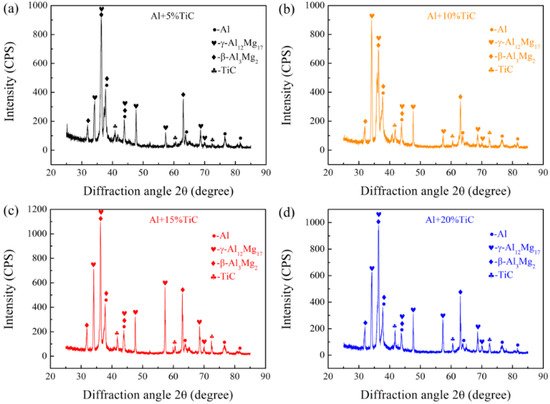
Figure 4.
XRD analysis of composite coatings: (a) Al+5wt%TiC; (b) Al+10wt%TiC; (c) Al+15wt%TiC; (d) Al+20wt%TiC.
Figure 5 is a Mg-Al binary phase diagram. When the content of Al is lower, the Al-Mg intermetallic compound at room temperature is γ-Al12Mg17; β-Al3Mg2 is the main Al-Mg intermetallic compound when the Al content is higher. In the laser cladding process, the AZ31B magnesium alloy has a dilution effect on the composite coating, and Mg will diffuse from the substrate into the cladding layer. The content of Mg gradually decreases from the bottom of the coating to the surface. In other words, the Al content in the coating increases with the increase of distance to the fusion line. Therefore, it can be concluded that the γ-Al12Mg17 is mainly distributed at the bottom of the cladding layer, while the β-Al3Mg2 exists in the middle and surface zones.
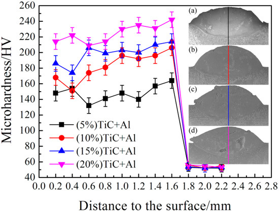
Figure 5.
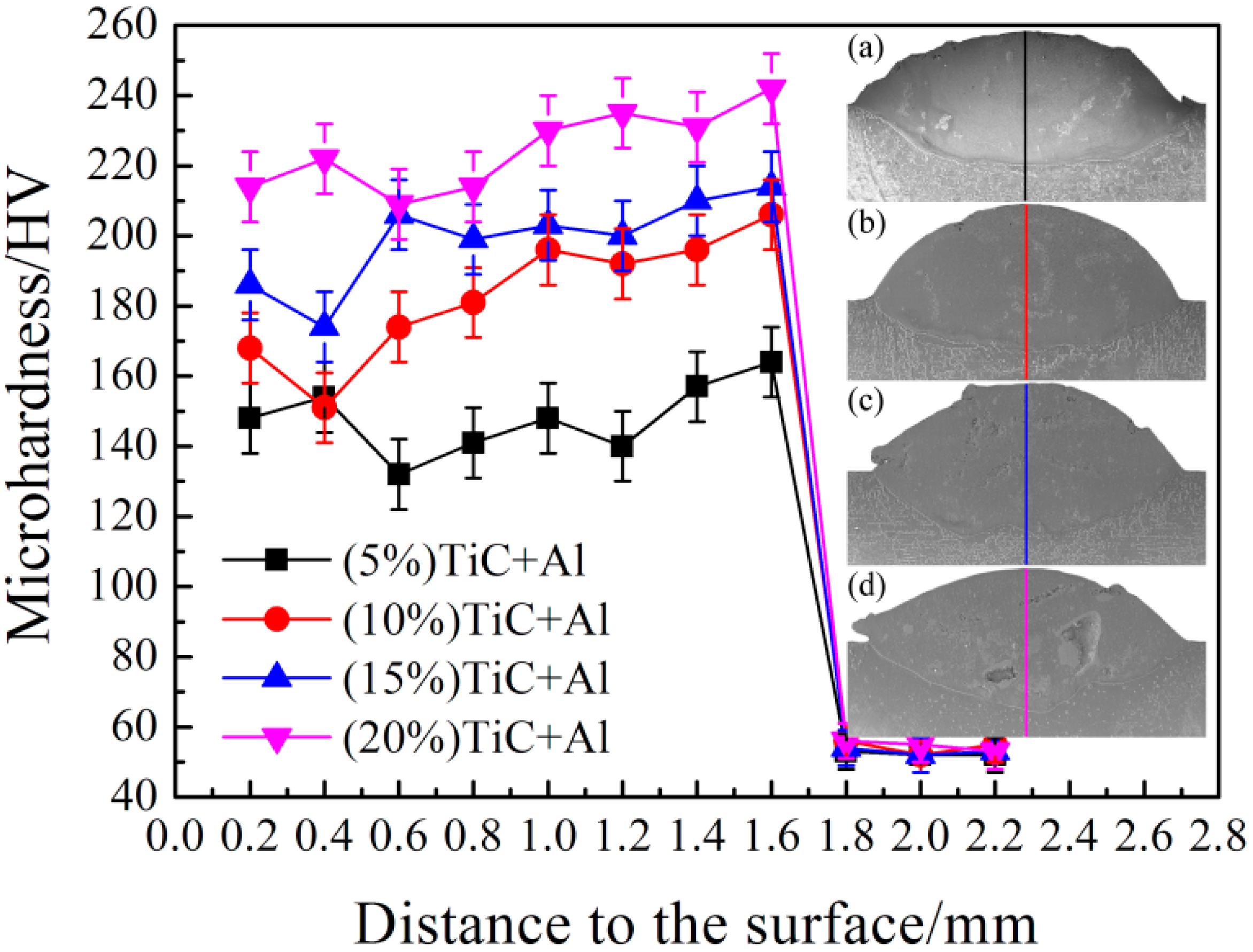
Microhardness distribution of the composite coating: (a) Al+5wt%TiC; (b) Al+10wt%TiC; (c) Al+15wt%TiC; (d) Al+20wt%TiC.
3.2. Mechanical Properties of the Coating
The microhardness distribution of the composite coating is shown in Figure 5. The path of the microhardness test avoided the agglomeration zone. It was found that the microhardness of the composite coating increased with increasing ceramic particle content. Furthermore, the fusion zone has a higher microhardness than the cladding layer.
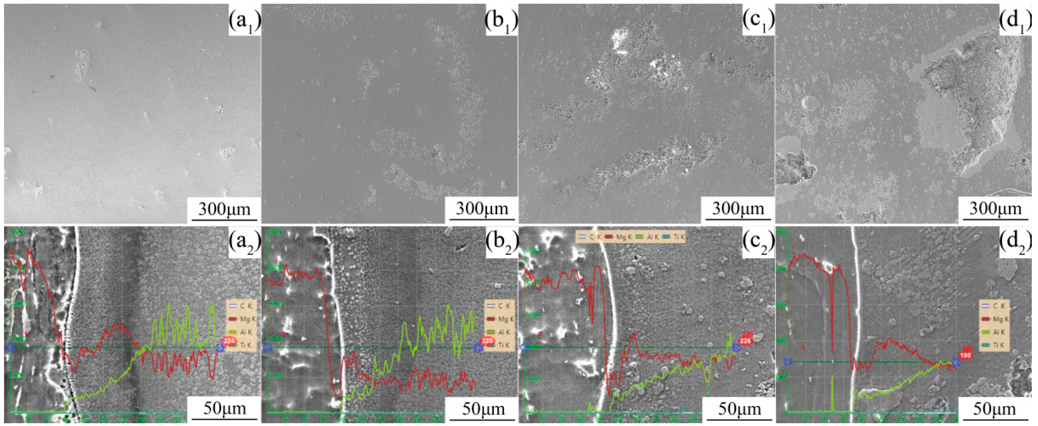
The microhardness of the composite coatings is mainly due to the matrix metal and ceramic particles. The agglomeration level increased with increasing TiC ceramic particle content, and the fine and dispersive particles content also increased, which is shown in Figure 6a1,b1,c1,d1. The hardness of ceramic particles is higher than that of the matrix metal, obviously, so the microhardness at the same location in different coatings increased with increasing TiC particle content. In the lower panels of Figure 6a2,b2,c2,d2), TiC particles are also distributed in the fusion zone. The Mg content in the fusion zone is larger than that in the coating middle area, and the distribution rule of the Al-Mg intermetallic compounds is verified again. The γ-Al12Mg17 phase has higher hardness than β-Al3Mg2 [21]. As a result, the microhardness in the fusion zone is higher than that in the middle area. In addition, the distribution of the TiC ceramic particles in the coating is uneven, so the microhardness value has a larger fluctuation.

Figure 6.
SEM morphology of coatings middle area and fusion zone, and microhardness distribution of the composite coating: (a1,b2) Al+5wt%TiC; (b1,b2) Al+10wt%TiC; (c1,c2) Al+15wt%TiC; (d1,d2) Al+20wt%TiC.
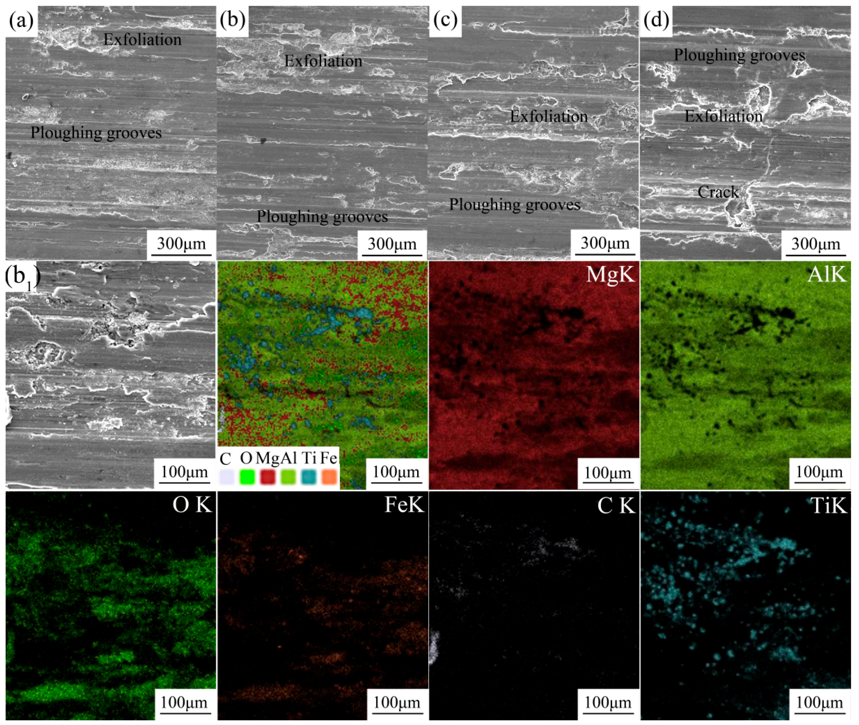
After adding more TiC ceramic particles, the wear volumes of the cladding layer are about 0.969 mm3, 0.706 mm3, 0.856 mm3, and 1.084 mm3, respectively. Each wear volume value is the average of 5 specimens. The wear volume and microhardness have different change laws. Although the high microhardness could improve the wear property of the coating, the fusion behavior weakens the binding force between the TiC ceramic particles and matrix metal. In the wear test, the fusion area will peel off under applied force; thus, the wear resistance of the cladding layer is destroyed. Figure 7a–d) shows the worn surface morphologies of laser-fused layers; the desquamation becomes more pronounced as the ceramic particle content increases. In particular, when the TiC content is 20wt%, some cracks appear in the worn surface. Figure 7b1 shows the elemental distribution on the worn surface of the 10wt%TiC specimen. In panel (b1), we first give the overall picture of element distribution. The distribution of each element can be seen in this picture. Elements Ti and C are mainly distributed on the desquamation area, but Al and Mg are uniformly distributed over the whole worn surface. The results illustrate that the agglomeration phenomenon of the TiC ceramic particles decreases the wear resistance of the coatings.

Figure 7.
Worn surface morphologies of laser-fused layers: (a) Al+5wt%TiC; (b) Al+10wt%TiC; (c) Al+15wt%TiC; (d) Al+20wt%TiC. Panel (b1) shows the elemental distribution on the worn surface of specimen (b).
3.3. Wear Mechanism Analysis
Ceramic particles segregated in the cladding layer metal caused the cohesion strength in this layer to deteriorate. In addition, the irregular ceramic particles or ceramic particle groups could become a crack source. The wear test is a dynamic process with pressure and relative motion. Hence, in the wear process, cracks formed around the ceramic particles and spread into the metal matrix; the segregated ceramic particles peeled off from the matrix due to the sliding motion of the test. The wear resistance of the cladding layer decreased because the number of hard particle points decreased. The segregation level of ceramic particles in the cladding layer become pronounced with increasing TiC content. Therefore, the wear resistance of the cladding layer decreased gradually.
Appropriate TiC ceramic particles content could effectively enhance the microhardness of the coatings, and the fine and dispersive TiC particles content and the agglomeration level is not too severe. Finally, the wear property of AZ31B magnesium alloy was solved effectively, which can widen its application range.
4. Conclusions
In this present work, Aluminum powders with different concentrations of TiC ceramic particles were applied to an AZ31B magnesium alloy by laser cladding. An appropriate TiC content improved the wear resistance of the cladding layer. The following main conclusions can be drawn:
- (1)
- The difference of coefficient of thermal expansion between TiC ceramic particles and coating metal caused a particle agglomeration phenomenon in the laser cladding processing.
- (2)
- TiC ceramic particles have many distribution patterns in the composite coatings.
- (3)
- The phases of cladding metal mainly consist of Al, γ-Al12Mg17, β-Al3Mg2, and TiC.
- (4)
- The microhardness of the cladding layer increases with increasing TiC ceramic particle content.
- (5)
- The agglomeration behavior of TiC ceramic particles greatly affects the wear resistance of the coatings.
Author Contributions
S.A. and T.W. conceived, designed the work; T.W., S.A. and Y.C. conducted the experiments; T.W., W.Z. and Y.C analyzed the data; T.W. and S.A. contributed to the writing of the original manuscript; Y.D. and Y.H. did the revision; S.A. and Z.L. supervised the whole procedure.
Funding
This research was funded by National Key R&D Program of China under Grant 2018YFB1107900, the National Natural Science Foundation of China under Grant 51575383; Natural Science Foundation of Tianjin City under Grant 18JCQNJC04100.
Conflicts of Interest
The authors declare no conflict of interest.
References
- Chen, E.; Zhang, K.; Zou, J. Laser Cladding of a Mg Based Mg–Gd–Y–Zr Alloy with Al–Si Powders. Appl. Surf. Sci. 2016, 367, 11–18. [Google Scholar] [CrossRef]
- Riquelme, A.; Escalera-Rodriguez, M.D.; Rodrigo, P.; Rams, J. Role of Laser Cladding Parameters in Composite Coating (Al-SiC) on Aluminum Alloy. J. Therm. Spray. Tech. 2016, 25, 1177–1191. [Google Scholar] [CrossRef]
- Sun, R.J.; Guan, Y.C.; Zhu, Y. Development of Laser Surface Technologies for Anti-corrosion on Magnesium Alloys: A Review. Surf. Rev. Lett. 2016, 23, 1–17. [Google Scholar] [CrossRef]
- Rolink, G.; Weisheit, A.; Biermann, T.; Bobzin, K.; Ote, M.; Linke, T.F.; Schulz, C.; Kelbassa, I. Investigations of Laser Clad, Thermal Sprayed and Laser Remelted AlSi20-Coatings on Magnesium Alloy AZ31B under Constant and Cycling Thermal Load. Surf. Coat. Tech. 2014, 259, 751–758. [Google Scholar] [CrossRef]
- Liang, Y.; Hu, S.S.; Shen, J.Q.; Zhang, H.; Wang, P. Geometrical and Microstructural Characteristics of the TIG-CMT Hybrid Welding in 6061 Aluminum Alloy Cladding. J. Mater. Process. Tech. 2017, 239, 18–30. [Google Scholar] [CrossRef]
- Feng, Y.Q.; Luo, Z.; Li, Y.; Ling, Z.X. A Novel Method for Resistance Plug Welding of 7075 Aluminum Alloy. Mater. Manuf. Process. 2016, 31, 2077–2083. [Google Scholar] [CrossRef]
- Wang, L.L.; Jin, L.; Huang, W.J.; Xu, M.; Xue, J.X. Effect of Thermal Frequency on AA6061 Aluminum Alloy Double Pulsed Gas Metal Arc Welding. Mater. Manuf. Process. 2016, 31, 2152–2157. [Google Scholar] [CrossRef]
- Wu, G.; Xu, R.; Kai, F. Retardation of Surface Corrosion of Biodegradable Magnesium-Based Materials by Aluminum Ion Implantation. Appl. Surf. Sci. 2012, 258, 7651–7657. [Google Scholar] [CrossRef]
- Liu, S.; Zhou, Y.F.; Xing, X.L.; Wang, J.B.; Yang, Q.X. Refining Effect of TiC on Primary M7C3 in Hypereutectic Fe-Cr-C Harden-Surface Welding Coating: Experimental Research and First-principles Calculation. J. Alloy. Compd. 2017, 691, 239–249. [Google Scholar] [CrossRef]
- Riquelme, A.; Rodrigo, P.; Escalera-Rodriguez, M.D.; Rams, J. Analysis and Optimization of Process Parameters in Al-SiCp Laser Cladding. Opt. Laser. Eng. 2016, 78, 165–173. [Google Scholar] [CrossRef]
- Sun, R.L.; Niu, W.; Lei, Y.W. Microstructure and Wear Resistance of Laser Clad Al-Si plus SiC Coatings on an AZ91D alloy. Laser. Eng. 2014, 28, 35–43. [Google Scholar]
- Zhu, R.D.; Li, Z.Y.; Li, X.X.; Sun, Q. Microstructure and Properties of the Low-Power-laser Clad Coatings on Magnesium Alloy with different amount of Rare Earth Addition. Appl. Surf. Sci. 2015, 353, 405–413. [Google Scholar] [CrossRef]
- Tan, C.; Zhu, H.; Kuang, T.; Shi, J.; Liu, H.; Liu, Z. Laser cladding al-based amorphous-nanocrystalline composite coatings on az80 magnesium alloy under water cooling condition. J. Alloy. Compd. 2017, 690, 108–115. [Google Scholar] [CrossRef]
- Wang, A.A.; Sircar, S.; Mazumder, J. Laser cladding of mg-al alloys. J. Mater. Sci. 1993, 28, 5113–5122. [Google Scholar] [CrossRef]
- Tan, H.; Luo, Z.; Li, Y.; Yan, F.; Duan, R.; Huang, Y. Effect of Strengthening Particles on the Dry Sliding Wear Behavior of Al2O3-M7C3/Fe Metal Matrix Composite Coatings Produced by Laser Cladding. Wear 2015, 324, 36–44. [Google Scholar] [CrossRef]
- Liu, K.; Li, Y.J.; Wang, J.; Ma, Q.S. Effect of High Dilution on the in Situ Synthesis of Ni-Zr/Zr-Si (B,C) Reinforced Composite Coating on Zirconium Alloy Substrate by Laser Cladding. Mater. Des. 2015, 87, 66–74. [Google Scholar] [CrossRef]
- Lin, Y.H.; Lei, Y.P.; Li, X.G.; Zhi, X.H.; Fu, H.G. A Study of TiB2/TiB Gradient Coating by Laser Cladding on Titanium Alloy. Opt. Laser. Eng. 2016, 82, 48–55. [Google Scholar] [CrossRef]
- Cai, Y.C.; Luo, Z.; Feng, M.M.Z.; Liu, M.Z.; Huang, Y.; Zeng, Y.D. The Effect of TiC/Al2O3 Composite Ceramic Reinforcement on Tribological Behavior of Laser Cladding Ni60Alloys Coatings. Surf. Coat. Tech. 2016, 291, 222–229. [Google Scholar] [CrossRef]
- Kulkarni, K.N.; Luo, A.A. Interdiffusion and Phase Growth Kinetics in Magnesium-aluminum Binary System. J. Phase. Equilib. Diff. 2013, 34, 104–115. [Google Scholar] [CrossRef]
- Cai, Y.C.; Luo, Z.; Zeng, Y.D. Influence of Deep Cryogenic Treatment on the Microstructure and Properties of AISI304 Austenitic Stainless Steel A-TIG Weld. Sci. Technol. Weld. Join. 2017, 22, 236–243. [Google Scholar] [CrossRef]
- Cao, R.; Wen, B.F.; Chen, J.H. Cold Metal Transfer Joining of Magnesium AZ31B-to-aluminum A6061-T6. Mater. Sci. Eng.-A. 2013, 560, 256–266. [Google Scholar] [CrossRef]


© 2018 by the authors. Licensee MDPI, Basel, Switzerland. This article is an open access article distributed under the terms and conditions of the Creative Commons Attribution (CC BY) license (http://creativecommons.org/licenses/by/4.0/).