The Effects of TIG Welding Rod Compositions on Microstructural and Mechanical Properties of Dissimilar AISI 304L and 420 Stainless Steel Welds


Abstract
:1. Introduction
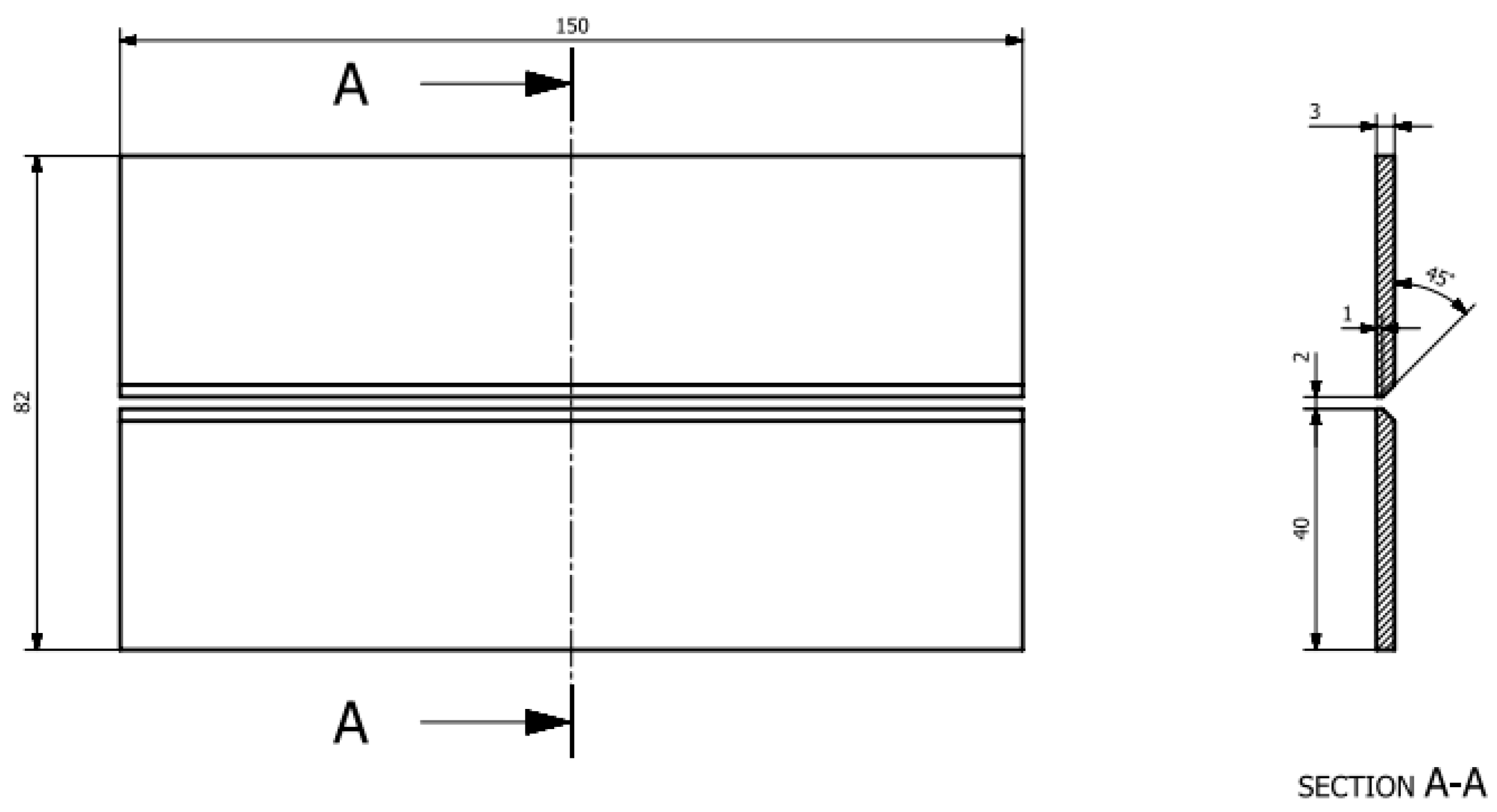
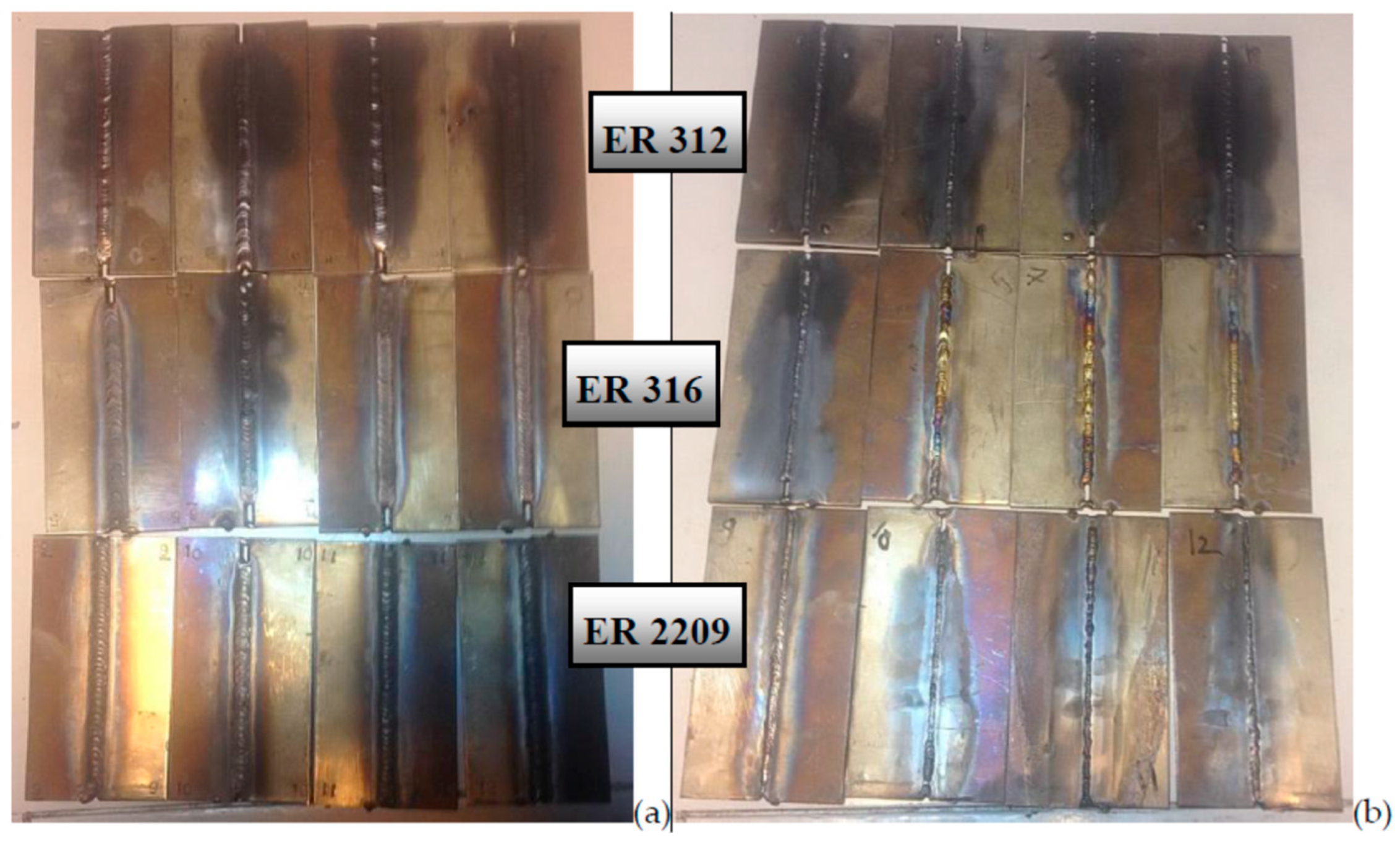
2. Materials and Methods
3. Results
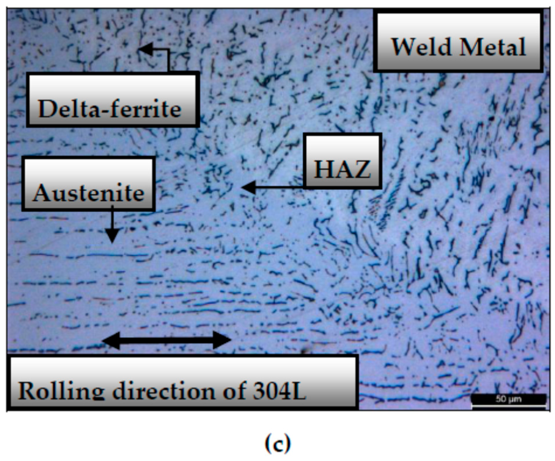
3.1. Microstructural Investigations
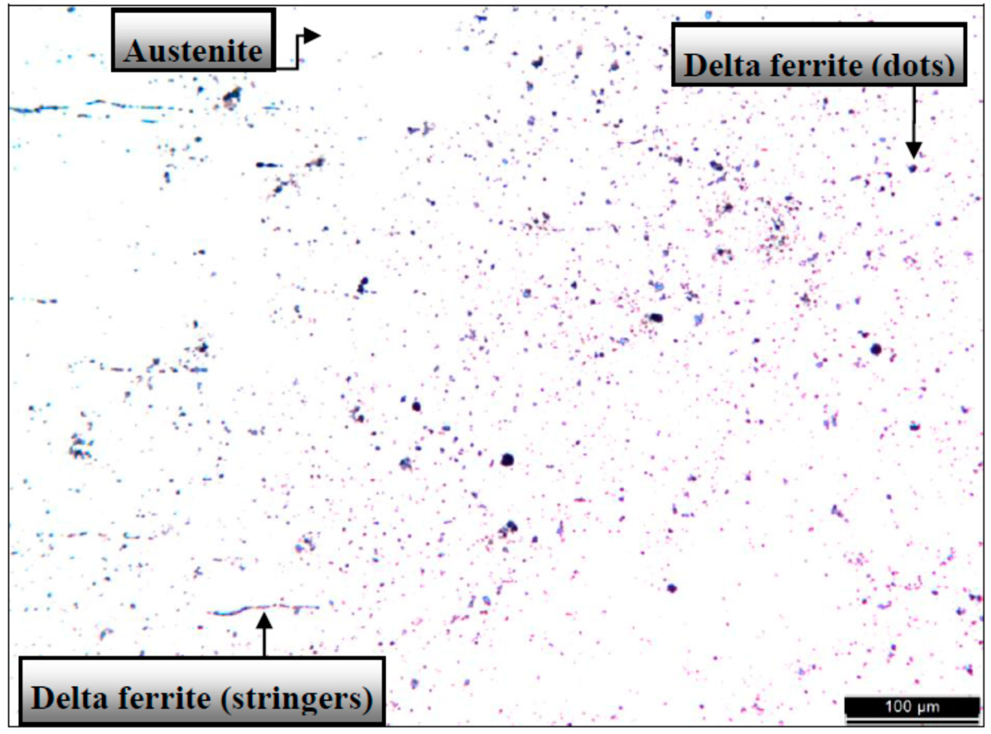
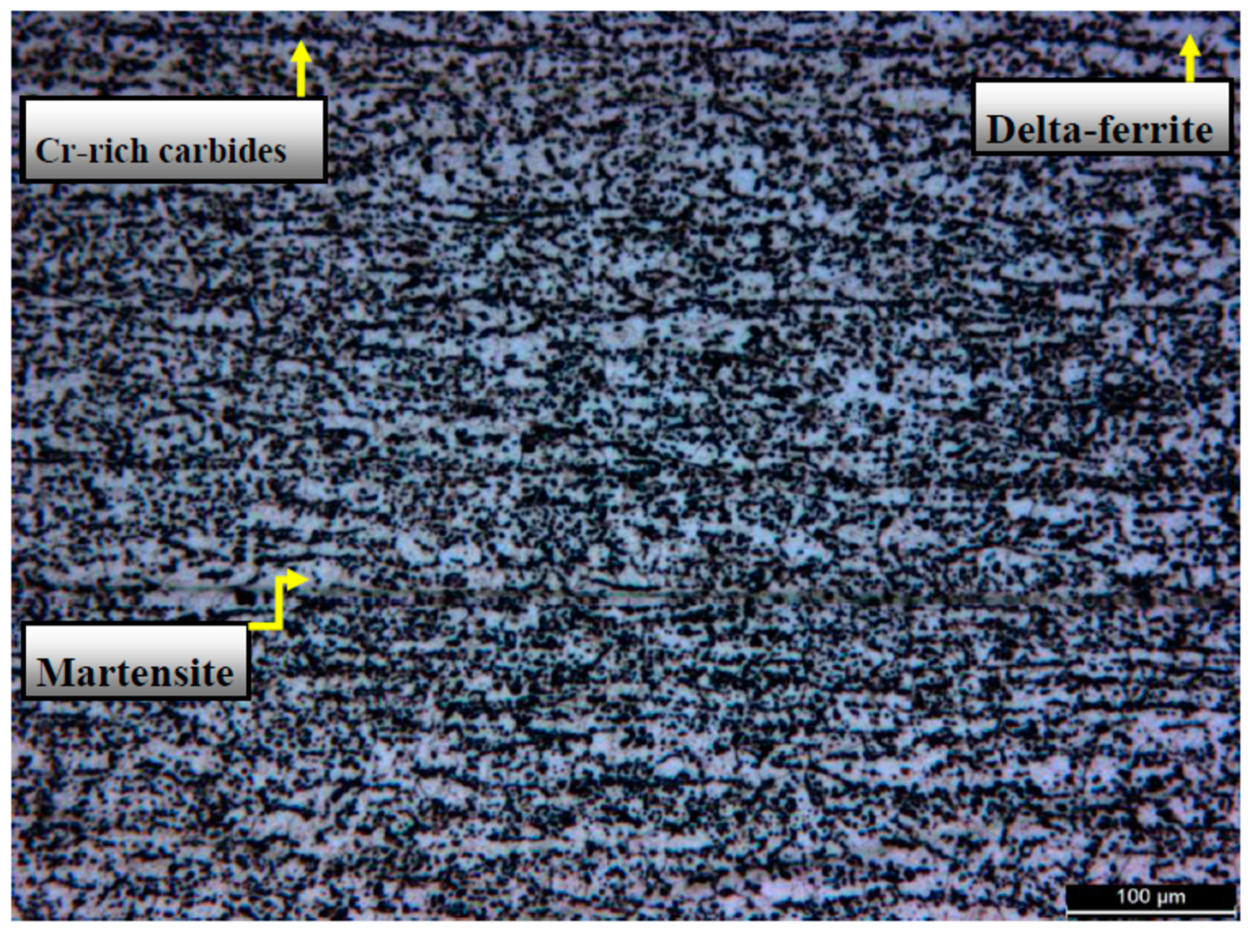
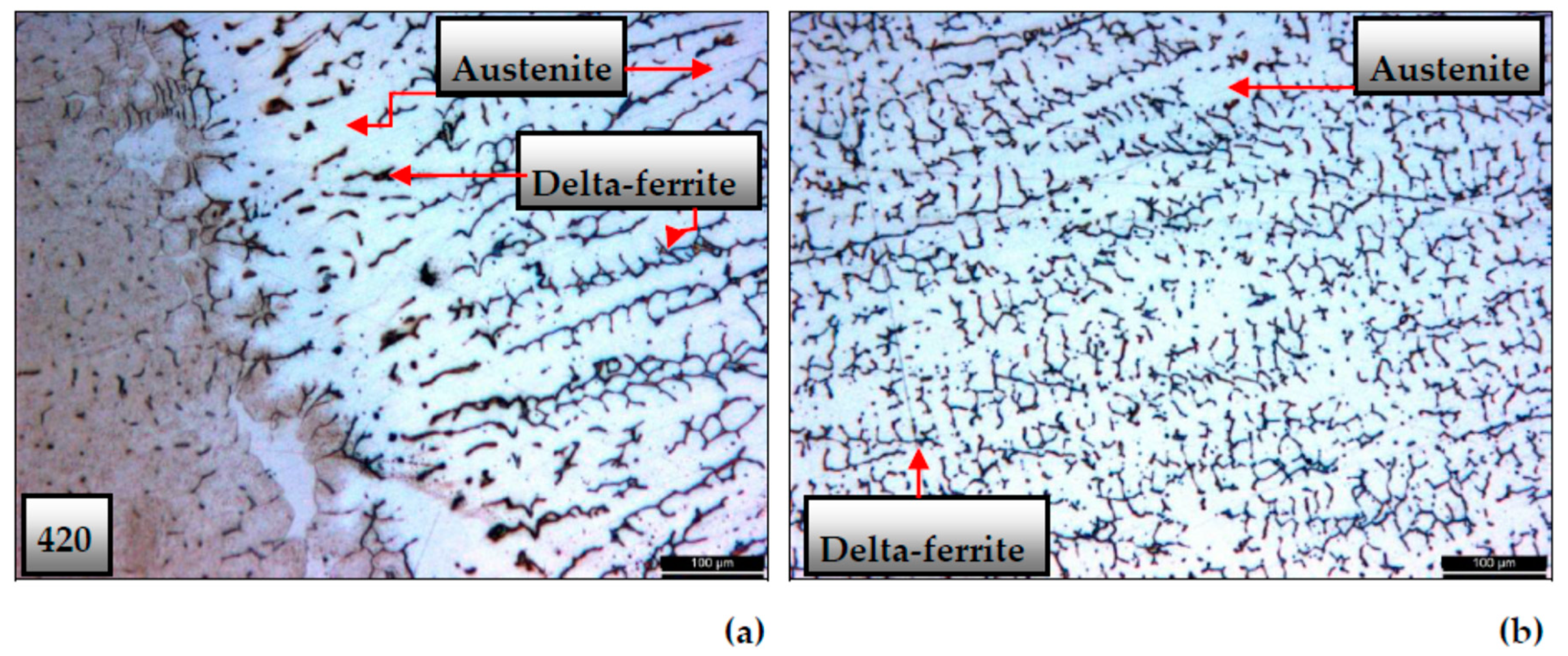
3.1.1. Microstructures of Base Metals
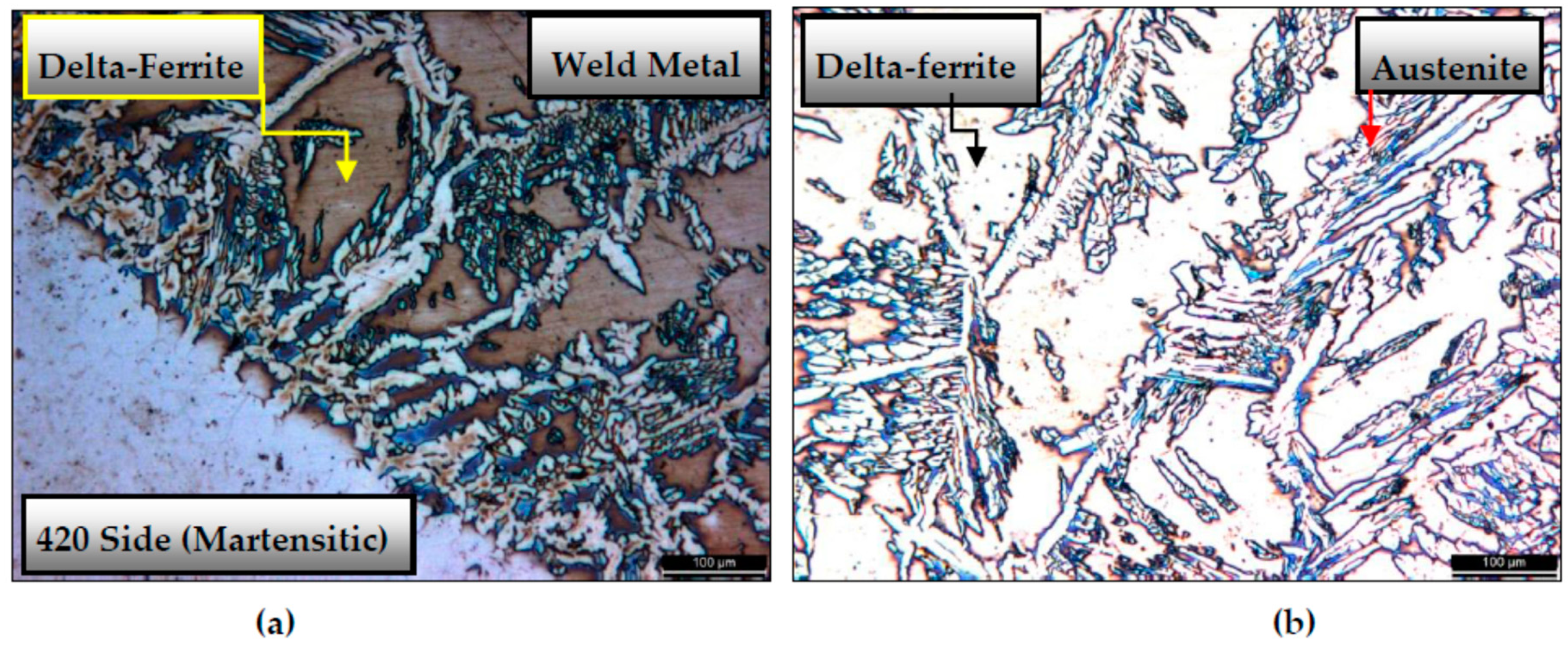
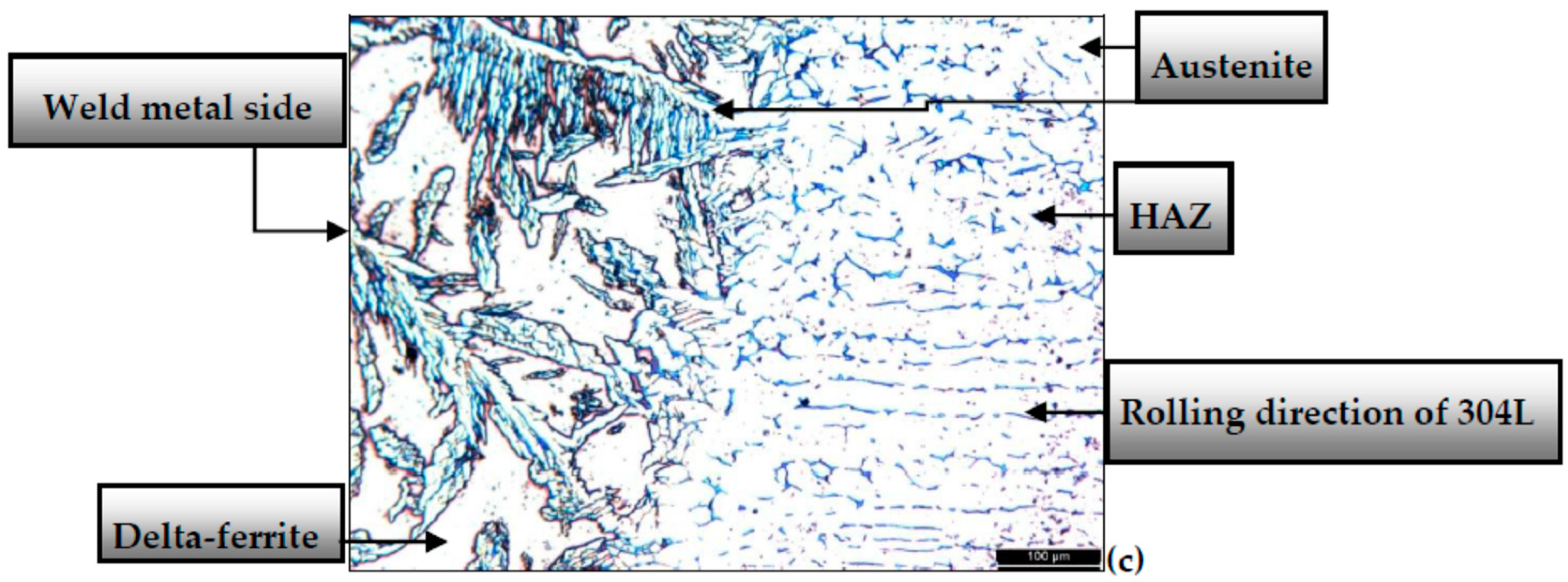
3.1.2. Microstructures of Samples Welded by ER312 TIG Rod
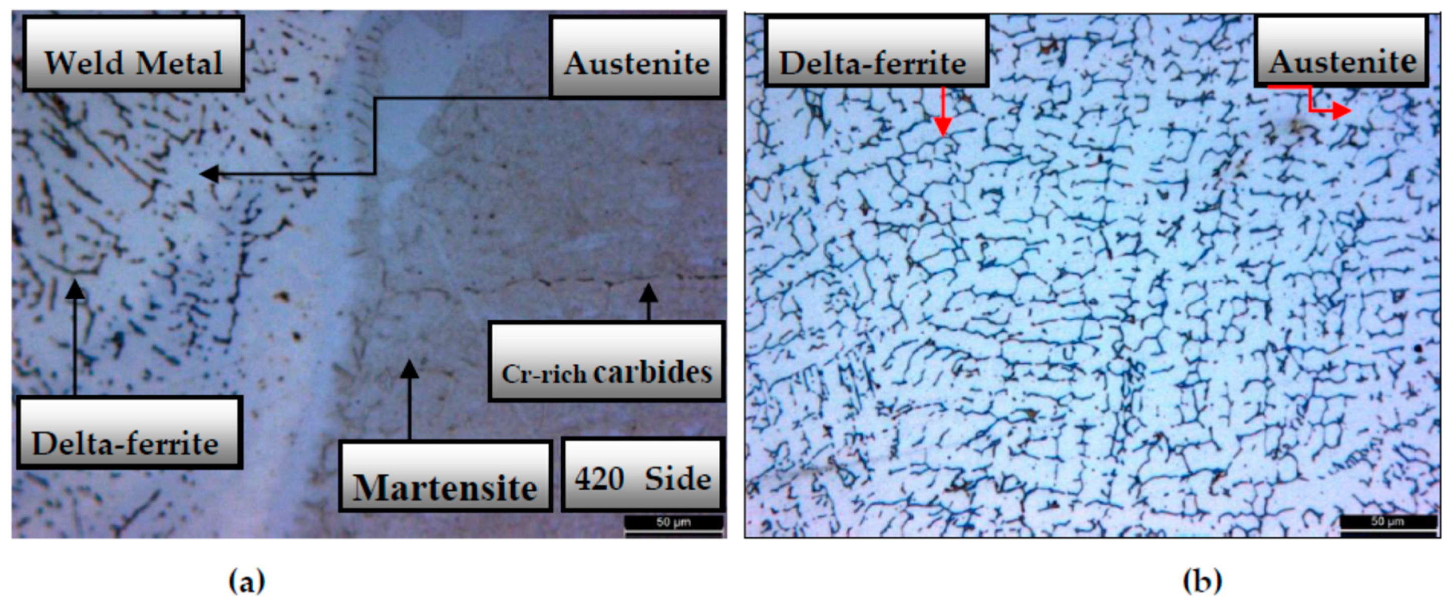
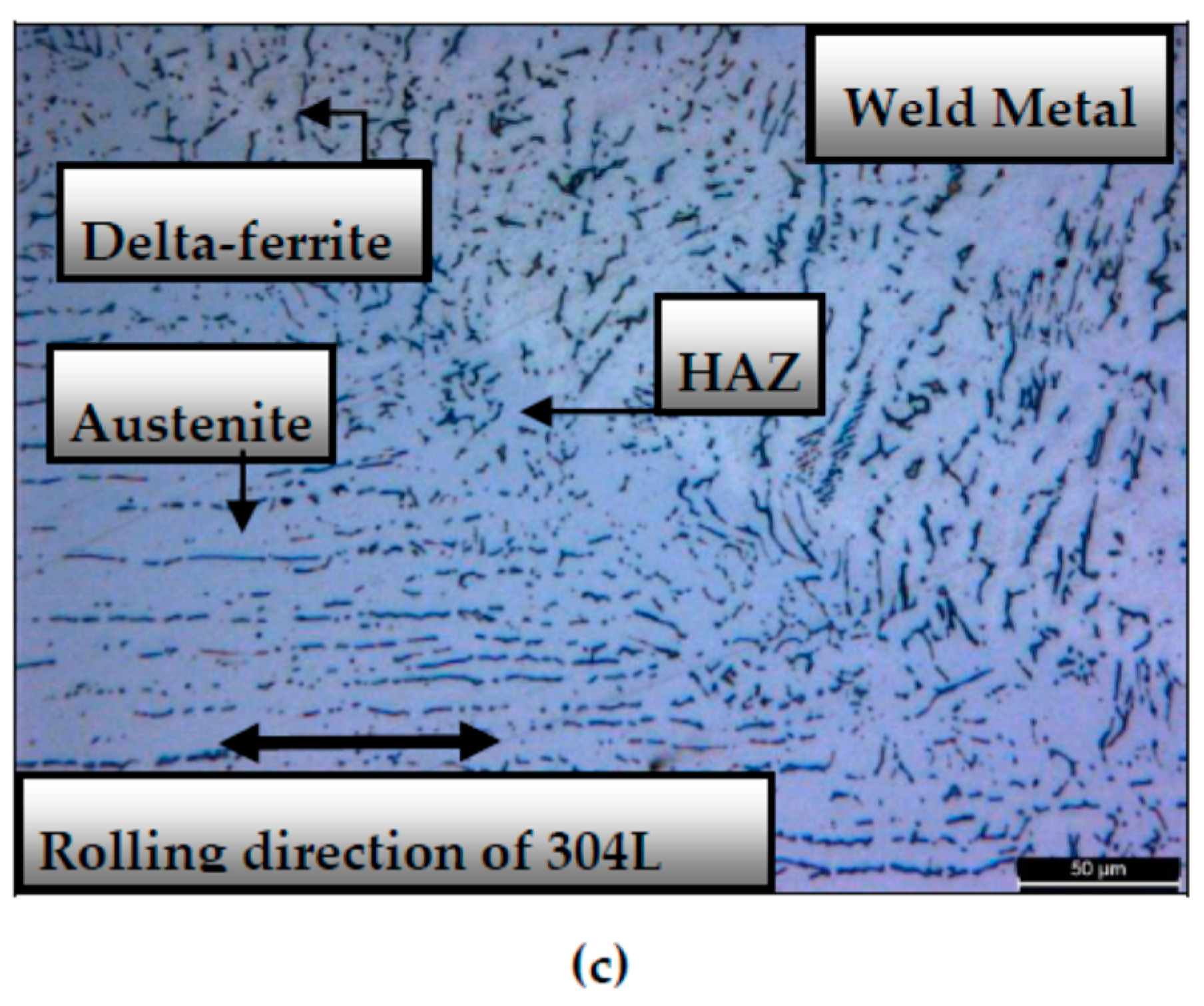
3.1.3. Microstructures of Samples Welded by ER316L TIG Rod
3.1.4. Microstructures of Samples Welded by ER2209 TIG Rod
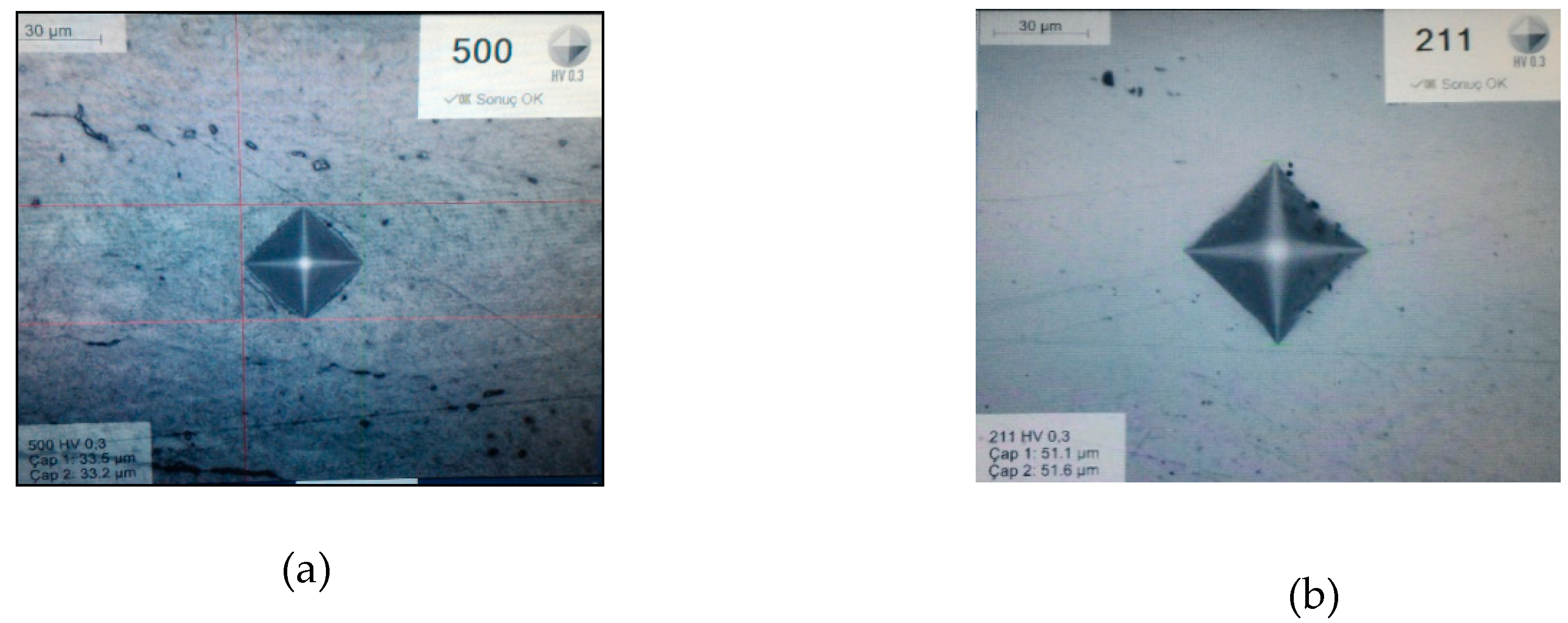
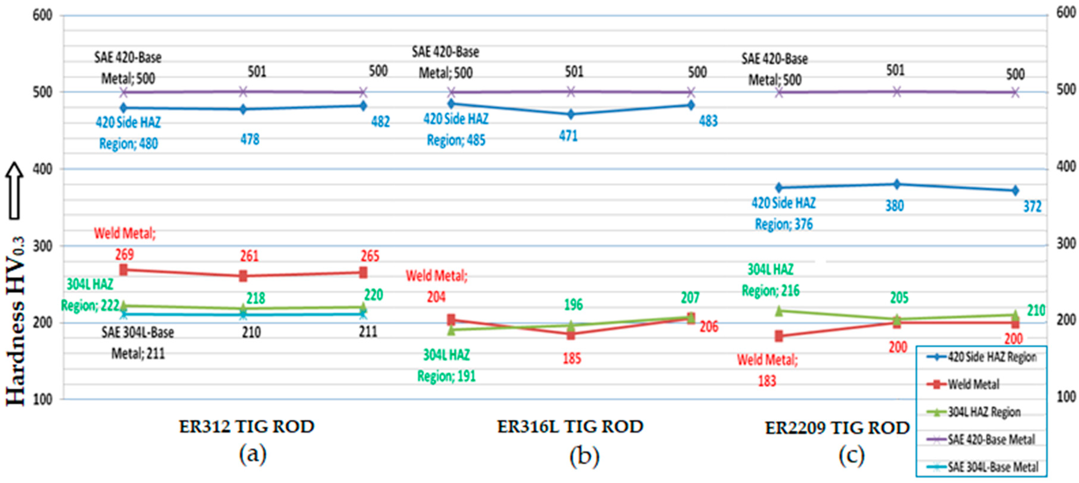
3.2. Micro-Hardness Inspections
3.2.1. Micro-Hardness Values of Base Metals
3.2.2. Micro-Hardness Values of Welded Samples
3.3. Impact Energy Tests
4. Discussion
5. Conclusions
Author Contributions
Funding
Acknowledgments
Conflicts of Interest
References
- ASM Handbook, Volume 1: Properties and Selection: Iron, Steel and High Performance Alloys; ASM International: Geauga, OH, USA, 2005; pp. 1311–1312.
- Lippold, J.; Kotecki, D. Welding Metallurgy and Weldability of Stainless Steels; Wiley Interscience Publications: Hoboken, NJ, USA, 2005; pp. 56, 67–79, 141–143, 343–345. [Google Scholar]
- ASM Metals Handbook Volume 6: Welding Brazing and Soldering; ASM International: Almere, The Netherlands, 1993; pp. 37, 1111–1113, 1170, 1181.
- Kou, S. Welding Metallurgy, 2nd ed.; Wiley Interscience Publications: Hoboken, NJ, USA, 2002; pp. 37, 43. [Google Scholar]
- ASM Metals Handbook Volume 4, Heat treating; ASM International: Almere, Netherlands, 1991; pp. 1694, 1697.
- Vander Voort, G.F. ASM Handbook Volume 9: Metallography and Microstructures; ASM International: Materials Park, OH, USA, 2004; pp. 670–700. [Google Scholar]
- Brandes, E.A.; Brook, G.B. Smithells Metals Reference Book, 7th ed.; Butterworth, Heinemann, Reed Elsevier Plc Group: Oxford, UK, 1999; pp. 10–40. [Google Scholar]
- ISO 15614-1. Specification and Qualification of Welding Procedures for Metallic Materials-Welding Procedure Test-Part 1: Arc and Gas Welding of Steels and Arc Welding of Nickel and Nickel Alloys; International Organization for Standardization: Geneva, Switzerland, 2017. [Google Scholar]
- ASTM A370. Standard Test Methods for Mechanical Testing of Steel Products; ASTM International: West Conshohocken, PA, USA, 2017. [Google Scholar]
- ASTM E23-12c. Standard Test Methods for Notched Bar Impact Testing of Metallic Materials; ASTM International: West Conshohocken, PA, USA, 2012. [Google Scholar]
- EN ISO 9015-2. Destructive Tests on Welds in Metallic Materials, Hardness Testing, Part 2: Micro-Hardness Test on Arc Welded Joints; International Organization for Standardization: Geneva, Switzerland, 2016. [Google Scholar]
- ASTM A240/A240M. Standard Specification for Chromium and Chromium-Nickel Stainless Steel Plate, Sheet and Strip for Pressure Vessels and for General Applications; ASTM International: West Conshohocken, PA, USA, 2017. [Google Scholar]
- AWS A5.9. Specification for Bare Stainless Steel Welding Electrodes and Rods; American Welding Society: Miami, FL, USA, 2017. [Google Scholar]
- EN ISO 14343. Welding Consumables, Wire Electrodes, Strip Electrodes, Wires and Rods for Arc Welding of Stainless and Heat Resisting Steels, Classification; International Organization for Standardization: Geneva, Switzerland, 2017. [Google Scholar]
- Tavares, S.S.M. Failure of super 13Cr stainless steel due to excessive hardness in the welded joint. Eng. Fail. Anal. 2018, 51, 92–98. [Google Scholar] [CrossRef]


| Material | Elements (weight %) | |||||||||||
|---|---|---|---|---|---|---|---|---|---|---|---|---|
| C | Si | Mn | P | S | Cr | Mo | Ni | V | N | Fe | Others | |
| 304L | 0.0264 | 0.379 | 1.19 | 0.0211 | 0.0030 | 18.23 | 0.0542 | 8.01 | 0.102 | 0.0695 | 71.6 | 0.9968 |
| 420 | 0.235 | 0.506 | 0.628 | 0.0133 | 0.0021 | 13.36 | 0.0067 | 0.141 | 0.0418 | 0.0228 | 84.9 | 0.1433 |
| AWS A5.9 [13], EN ISO 14343-A [14] TIG Rods | Elements (weight %) | |||||||
|---|---|---|---|---|---|---|---|---|
| C | Mn | Si | Ni | Cr | Mo | Cu | N | |
| ER312 | 0.15 | 1.6 | 0.4 | 8.8 | 30.7 | 0.2 | 0.14 | - |
| ER316L | 0.01 | 1.7 | 0.4 | 12 | 18.2 | 2.6 | 0.10 | 0.04 |
| ER2209 | 0.01 | 1.5 | 0.5 | 8.5 | 22.7 | 3.2 | 0.01 | 0.17 |
| TIG Welding Rod | Welding Current DC(−) (Amperes) | Welding Voltage (Volts) | Pure Argon Shielding Gas Flow (l/min) | Welding Speed (mm/sec.) | Welding Heat Input (Joule/mm) | TIG Welding Electrode Type | |||||
|---|---|---|---|---|---|---|---|---|---|---|---|
| (Ø2.0 mm) | Root Pass | 2nd. Pass | Root Pass | 2nd. Pass | Root Pass | 2nd. Pass | Root Pass | 2nd. Pass | Root Pass | 2nd. Pass | |
| ER312 | 65–70 | 90–95 | 9 | 11 | 10 | 6 | 2.33 | 2.16 | 185.70 | 326.72 | WT 20 (red) (2% Thoriated) Ø2.4 mm |
| ER316L | 2.29 | 2.18 | |||||||||
| ER2209 | 2.25 | 2.20 | |||||||||
| Microvickers Hardness (HV0.3) | |||
|---|---|---|---|
| Test No. | Specimen welded by ER312 TIG Rod | ||
| 420 HAZ | Weld Metal | 304L HAZ | |
| 1 | 480 | 269 | 222 |
| 2 | 478 | 261 | 218 |
| 3 | 482 | 265 | 220 |
| Mean value | 480 | 265 | 220 |
| Standard Deviation | 2 | 4 | 2 |
| Test No. | Specimen welded by ER316L TIG Rod | ||
| 420 HAZ | Weld Metal | 304L HAZ | |
| 1 | 485 | 204 | 191 |
| 2 | 471 | 185 | 196 |
| 3 | 483 | 206 | 207 |
| Mean value | 480 | 198 | 198 |
| Standard Deviation | 7.57 | 11.59 | 8.18 |
| Test No. | Specimen welded by ER2209 TIG Rod | ||
| 420 HAZ | Weld Metal | 304L HAZ | |
| 1 | 376 | 183 | 216 |
| 2 | 380 | 200 | 205 |
| 3 | 372 | 200 | 210 |
| Mean value | 376 | 194 | 210 |
| Standard Deviation | 4 | 9.81 | 5.51 |
| Base Metal | Specimen No. | kgm | JOULE (kg·m2/s2) |
|---|---|---|---|
| 304L | 1 | 3.80 | 37.278 |
| 2 | 4.20 | 41.202 | |
| 3 | 4.10 | 40,221 | |
| 4 | 4.00 | 39.240 | |
| Average Value | 4.03 | 39.485 | |
| Standard Deviation | 0.17 | 1.68 | |
| 420 | 1 | 2.50 | 24.525 |
| 2 | 2.50 | 24.525 | |
| 3 | 2.50 | 24.525 | |
| 4 | 2.40 | 23.544 | |
| Average Value | 2.48 | 24.279 | |
| Standard Deviation | 0.05 | 0.49 |
| TIG Welding Rod Type | ||||||||
|---|---|---|---|---|---|---|---|---|
| ER312 | ER316L | ER2209 | ||||||
| Specimen No. | kgm | JOULE (kg·m2/s2) | Specimen No. | kgm | JOULE (kg·m2/s2) | Specimen No. | kgm | JOULE (kg·m2/s2) |
| 1 | 2.80 | 27.47 | 6 | 3.20 | 31.39 | 11 | 4.60 | 45.13 |
| 3 | 2.40 | 23.54 | 6 | 3.20 | 31.39 | 11 | 4.50 | 44.15 |
| 3 | 2.50 | 24.53 | 6 | 3.20 | 31.39 | 12 | 4.40 | 43.16 |
| 3 | 2.60 | 25.51 | 7 | 3.50 | 34.34 | 12 | 4.50 | 44.15 |
| 4 | 2.90 | 28.45 | 7 | 3.40 | 33.35 | 13 | 3.30 | 32.37 |
| 4 | 2.80 | 27.47 | 8 | 3.20 | 31.39 | 14 | 4.20 | 41.20 |
| 5 | 2.70 | 26.49 | 8 | 3.40 | 33.35 | 14 | 4.50 | 44.15 |
| 5 | 2.80 | 27.47 | 10 | 3.60 | 35.32 | 15 | 4.50 | 44.15 |
| Mean Value | 2.69 | 26.36 | Mean Value | 3.3375 | 32.74 | Mean Value | 4.3125 | 42.31 |
| Standard Deviation | 0.17 | 1.69 | Standard Deviation | 0.16 | 1.57 | Standard Deviation | 0.43 | 4.18 |
© 2018 by the authors. Licensee MDPI, Basel, Switzerland. This article is an open access article distributed under the terms and conditions of the Creative Commons Attribution (CC BY) license (http://creativecommons.org/licenses/by/4.0/).
Share and Cite
Başyiğit, A.B.; Murat, M.G. The Effects of TIG Welding Rod Compositions on Microstructural and Mechanical Properties of Dissimilar AISI 304L and 420 Stainless Steel Welds. Metals 2018, 8, 972. https://doi.org/10.3390/met8110972
Başyiğit AB, Murat MG. The Effects of TIG Welding Rod Compositions on Microstructural and Mechanical Properties of Dissimilar AISI 304L and 420 Stainless Steel Welds. Metals. 2018; 8(11):972. https://doi.org/10.3390/met8110972
Chicago/Turabian StyleBaşyiğit, Aziz Barış, and Mustafa Gökhan Murat. 2018. "The Effects of TIG Welding Rod Compositions on Microstructural and Mechanical Properties of Dissimilar AISI 304L and 420 Stainless Steel Welds" Metals 8, no. 11: 972. https://doi.org/10.3390/met8110972
APA StyleBaşyiğit, A. B., & Murat, M. G. (2018). The Effects of TIG Welding Rod Compositions on Microstructural and Mechanical Properties of Dissimilar AISI 304L and 420 Stainless Steel Welds. Metals, 8(11), 972. https://doi.org/10.3390/met8110972