1. Introduction
Ratcheting is a progressively accumulated inelastic strain under cyclic stressing with a non-zero mean stress. In the process of life prediction and safety assessment, both ASME and RCC-M codes specify that the ratcheting deformation occurring in structural components of nuclear reactor must be addressed. Numerous experiments were carried out to reveal the evolutions of ratcheting behaviors and many nonlinear kinematic hardening models were established to predict ratcheting deformation at different loading conditions [
1,
2,
3,
4]. Commercial finite element software, such as ANSYS and ABAQUS, are widely applied in engineering design and analysis. The nonlinear kinematic hardening rule, such as the Chaboche’s rule [
5], is available in these commercial software tools, which can capture the cyclic plastic deformation of some metal materials. For example, a Chaboche-type material model was applied in the Low-Cycle Fatigue finite element assessment on 316L pipes for the “Wendelstein 7-X” stellarator-type nuclear fusion experiment [
6], but it commonly gives a conservative prediction [
7].
To reasonably describe ratcheting behaviors of different materials, suitable modifications in the kinematic hardening rule are necessary. For example, the material parameter
mi in the Ohno-Wang II kinematic hardening rule [
8,
9] was modified as a function of the maximum equivalent stress to improve simulation for ratcheting behaviors of AZ31B magnesium alloy by Lin et al. [
10]. To improve the predictions of plastic shakedown and ratcheting behavior of 7075-T6 aluminum alloy, one of three nonlinear backstress components was replaced as a linear term based on the superposed Armstrong-Frederick rule [
11]. Besides, Chen et al. [
12] proposed a unified viscoplastic model to simulate the time-dependent ratcheting behavior and low cycle fatigue of 316L stainless steel, and provide satisfactory predictions for most experimental results. Focusing on a wide range of heat treatments, the Kocks-Mecking-Estrin model [
13] was adopted to predict the cyclic deformation behavior and residual stress of 690 nickel alloy during and after welding.
It must be noted that different materials exhibit different ratcheting behaviors [
14]. SA508-3 steel, one kind of nuclear material, is widely used in the nuclear reactor pressure vessel (RPV) of the pressurized water reactor (PWR). The RPV is a piece of key equipment for the first loop of the nuclear plant, of which the structural integrity directly affects the service life of the whole plant. The working temperature of the pressure vessel varies from 25 °C to 350 °C, and the cyclic thermal and mechanical loadings always run through the whole lifetime. Besides, SA508-3 steel is one of the alloyed ferritic steels. Notable cyclic softening at elevated temperature was observed in the experiments of alloyed ferritic steels, which is totally different from the characteristics of carbon steels and austenitic stainless steels [
15]. Therefore, it is worthwhile to develop the temperature-dependent cyclic plastic model for the nuclear material of SA508-3 steel.
Moreover, one of main purposes to develop cyclic plastic models is to simulate the accumulations of plastic strain of structural components under cyclic loadings by finite element method (FEM), which is a foundation to understand the fatigue failure of engineering structures. Therefore, it is necessary to implement these advanced cyclic plastic models into finite element codes. In the process of finite element implementation, the following two problems should be highlighted: one is to determine the stress integration algorithm at each Gauss integration point, the other is to derive the consistent tangent modulus for the equilibrium iteration of finite element analysis. Many progresses have been made to implement cyclic plastic models into commercial finite element softwares, such as ANSYS, ABAQUS, and so on. For example, based on the Abdel Karim-Ohno kinematic hardening rule [
16], a cyclic plastic model with a memory surface was implemented into the finite element code ANSYS by using the UMAT [
17], which provided a good prediction of the additional hardening caused by the non-proportional loading path. Considering the true stress instead of the effective stress in the yield function, the damage-coupled cyclic plastic model proposed by Bonora [
18] was implemented into the finite element code, and an implicit method with an explicit update was used to solve the system of non-linear equations instead of a matrix inversion. An optimization by successive iterations was applied to obtain optimal parameters of the Chaboche model, and the cyclic deformations of nuclear installations [
19] made of 316L-N, 316L, and 304L, were successfully simulated. Besides, a multi-objective genetic algorithm was also applied to optimize the parameters of the Chaboche model for 7075-T6 aluminum alloy [
20].
Motivated by the above considerations, the present work aims to implement a temperature-dependent cyclic plastic model into finite element software ABAQUS by using the UMAT for SA508-3 steel. The organization of this work is below: firstly, a brief introduction on the Chaboche model is presented. Then, based on the Chaboche model, the discrete material constants are modified into a continuous function corresponding to the accumulated plastic strain. The finite element implementation of the modified model is addressed in detail, including the discretization of constitutive equations, implicit stress integration and derivation of consistent tangent modulus. Finally, finite element models of structures including a notched bar and a plate with a center hole are established, and simulations are carried out to verify the implementation of the present temperature-dependent cyclic plastic model.
2. Temperature-Dependent Cyclic Plastic Model
Considering the temperature term and on the basis of the plastic flow rule at small deformation as well as the initial isotropic elasticity, the total strain rate
can be written as the sum of three parts, i.e., the elastic strain rate
, plastic strain rate
and thermal strain rate
.
According to the Hooke’s law, the elastic constitutive relation can be expressed as following:
where
denotes the temperature-dependent fourth-order elastic tensor,
is the stress rate tensor.
The plastic strain rate is formulated based on the flow rule as:
where
is the accumulated plastic strain rate,
and
represent the deviatoric stress and backstress tensors, respectively.
denotes the norm.
The thermal strain rate is defined as:
where
is the thermal expansion coefficient and
is the rate of temperature.
is the second-order unit tensor.
The von Mises yield surface can be written in the general form:
where
represents the isotropic deformation resistance and reflects the change in the radius of yield surface.
The nonlinear kinematic hardening rule revealing the evolution of backstress makes it possible to describe the progressive ratcheting deformation. Based on the Armstrong-Frederick’s rule [
21], Chaboche [
5] firstly decomposed the backstress of into several components, which can be expressed as:
where
and
are material constants and
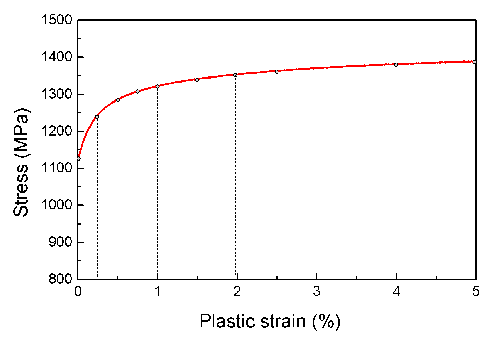
is the number of decomposed backstress components. If the number of components increases, a higher prediction accuracy in the accumulation of plastic strain will be obtained, that is, the curve of stress versus plastic strain will be correspondingly divided into more parts (as shown in
Figure 1), but it would cost greater computational consumption.
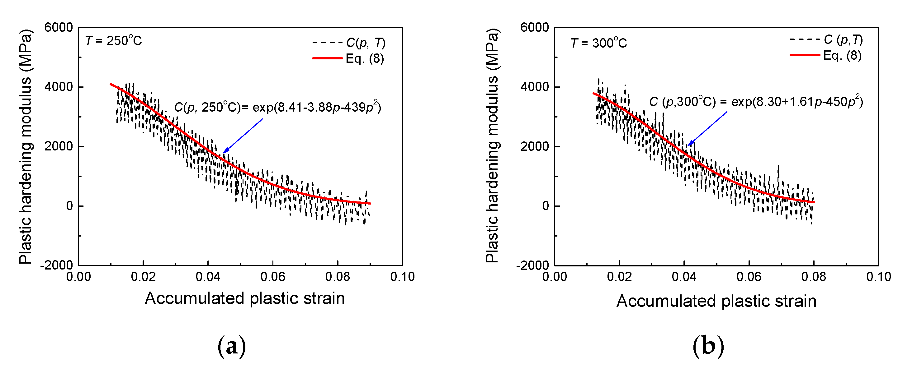
It is noted that the plastic hardening moduli
can be calculated by differentiating the curve of stress versus accumulated plastic strain with fixed
.
Figure 2 shows an exponential function of the plastic hardening modulus
with respect to the accumulated plastic strain at 250 °C and 300 °C, respectively.
Therefore, an exponential relationship can be used to describe the dependence of the plastic hardening moduli
on the accumulated plastic strain and temperature as:
where
,
and
are material constants and can be determined by fitting the corresponding experimental results. Therefore, the evolution of backstress in the kinematic hardening rule can be modified as:
where
represents the function of the accumulated plastic strain
and the temperature
, and
is only relevant to
.
Considering the temperature dependence of the isotropic hardening, the temperature-dependent isotropic deformation resistance
is expressed as:
where
is a material parameter controlling the rate of resistance
;
represents the saturated isotropic deformation resistance only related to temperature. It should be noted that, when the accumulated plastic strain equals to zero, the initial deformation resistance
can be determined from Equation (10). For cyclic softening or cyclic hardening materials, it is observed that the initial deformation resistance
in tensile tests is apparently different from that in the subsequent cycles, so the initial value of
should be changed at the end of tensile curve in the first cycle.
Author Contributions
Methodology, J.T. and J.L.; Supervision, H.X., Y.Y. and Q.K.; Writing—original draft, J.T.; Writing—review & editing, Q.K.
Funding
This research was funded by the National key research and development program (2016YFB1102601), National Natural Science Foundation of China (11572265), the Excellent Youth Found of Sichuan Province (2017JQ0019) and Exploration Project of Traction Power State Key Laboratory (2017TPLT04) are acknowledged.
Conflicts of Interest
The authors declare no conflict of interest.
References
- Bari, S.; Hassan, T. Anatomy of coupled constitutive models for ratcheting simulation. Int. J. Plast. 2000, 16, 381–409. [Google Scholar] [CrossRef]
- Bari, S.; Hassan, T. Kinematic hardening rules in uncoupled modeling for multiaxial ratcheting simulation. Int. J. Plast. 2001, 17, 885–905. [Google Scholar] [CrossRef]
- Kang, G. Ratchetting: Recent progresses in phenomenon observation, constitutive modeling and application. Int. J. Fatigue 2008, 30, 1448–1472. [Google Scholar] [CrossRef]
- Chen, X.H.; Chen, X.; Yu, D.; Gao, B.J. Recent progresses in experimental investigation and finite element analysis of ratcheting in pressurized piping. Int. J. Press. Vessels Pip. 2013, 101, 113–142. [Google Scholar] [CrossRef]
- Chaboche, J.L. Time-independent constitutive theories for cyclic plasticity. Int. J. Plast. 1986, 2, 149–188. [Google Scholar] [CrossRef]
- Giannella, V.; Citarella, R.; Fellinger, J.; Esposito, R. LCF assessment on heat shield components of nuclear fusion experiment “Wendelstein 7-X” by critical plane criteria. Procedia Struct. Integr. 2018, 8, 318–331. [Google Scholar] [CrossRef]
- Kalnins, A.; Rudolph, J.; Willuweit, A. Using the Nonlinear Kinematic Hardening Material Model of Chaboche for Elastic-Plastic Ratcheting Analysis. J. Press. Vessel Technol. Trans. ASME 2015, 137, 10. [Google Scholar] [CrossRef]
- Ohno, N.; Wang, J.D. Kinematic hardening rules with critical state of dynamic recovery, part I: Formulation and basic features for ratchetting behavior. Int. J. Plast. 1993, 9, 375–390. [Google Scholar] [CrossRef]
- Ohno, N.; Wang, J.D. Kinematic hardening rules with critical state of dynamic recovery, part II: Application to experiments of ratchetting behavior. Int. J. Plast. 1993, 9, 391–403. [Google Scholar] [CrossRef]
- Lin, Y.C.; Liu, Z.H.; Chen, X.M.; Long, Z.L. Cyclic Plasticity Constitutive Model for Uniaxial Ratcheting Behavior of AZ31B Magnesium Alloy. J. Mater. Eng. Perform. 2015, 24, 1820–1833. [Google Scholar] [CrossRef]
- Agius, D.; Kourousis, K.I.; Wallbrink, C.; Hu, W.; Wang, C.H.; Dafalias, Y.F. Aluminum Alloy 7075 Ratcheting and Plastic Shakedown Evaluation with the Multiplicative Armstrong–Frederick Model. AIAA J. 2017, 55, 2461–2470. [Google Scholar] [CrossRef]
- Chen, W.; Kitamura, T.; Feng, M. Creep and fatigue behavior of 316L stainless steel at room temperature: Experiments and a revisit of a unified viscoplasticity model. Int. J. Fatigue 2018, 112, 70–77. [Google Scholar] [CrossRef]
- Blaizot, J.; Chaise, T.; Nélias, D.; Perez, M.; Cazottes, S.; Chaudet, P. Constitutive model for nickel alloy 690 ( Inconel 690 ) at various strain rates and temperatures. Int. J. Plast. 2016, 80, 139–153. [Google Scholar] [CrossRef]
- Kang, G.; Liu, Y. Uniaxial ratchetting and low-cycle fatigue failure of the steel with cyclic stabilizing or softening feature. Mater. Sci. Eng. A 2008, 472, 258–268. [Google Scholar] [CrossRef]
- Yaguchi, M.; Takahashi, Y. Ratchetting of viscoplastic material with cyclic softening, part 2: Application of constitutive models. Int. J. Plast. 2005, 21, 835–860. [Google Scholar] [CrossRef]
- Abdel-Karim, M.; Ohno, N. Kinematic hardening model suitable for ratchetting with steady-state. Int. J. Plast. 2000, 16, 225–240. [Google Scholar] [CrossRef]
- Halama, R.; Markopoulos, A.; Jančo, R.; Bartecký, M. Implementation of MAKOC cyclic plasticity model with memory. Adv. Eng. Softw. 2017, 113, 34–46. [Google Scholar] [CrossRef]
- Bonora, N.; Majzoobi, G.H.; Khademi, E. Numerical implementation of a new coupled cyclic plasticity and continum damage model. Comput. Mater. Sci. 2014, 81, 538–547. [Google Scholar] [CrossRef]
- Dalla Palma, M. Modelling of cyclic plasticity for austenitic stainless steels 304L, 316L, 316L(N)-IG. Fusion Eng. Des. 2016, 109–111, 20–25. [Google Scholar] [CrossRef]
- Agius, D.; Kajtaz, M.; Kourousis, K.I.; Wallbrink, C.; Wang, C.H.; Hu, W.; Silva, J. Sensitivity and optimisation of the Chaboche plasticity model parameters in strain-life fatigue predictions. Mater. Des. 2017, 118, 107–121. [Google Scholar] [CrossRef]
- Frederick, C.O.; Armstrong, P.J. A Mathematical Representation of the Multiaxial Bauscinger Effect. Mater. High Temp. 1998, 24, 1–26. [Google Scholar]
- Kobayashi, M.; Ohno, N. Implementation of cyclic plasticity models based on a general form of kinematic hardening. Int. J. Numer. Methods Eng. 2002, 53, 2217–2238. [Google Scholar] [CrossRef]
- Liu, J.; Wang, L.; Yang, Y.; Cui, J. Fracture toughness and behavior of SA508-III steel under different loading rates. Heat Treat. Met. 2017, 42, 42–46. [Google Scholar]
- Tomlinson, S.M.; Lopez-Anido, R.A. Scale and manufacturing effects on tensile strength of marine grade sandwich composite panel joints. J. Sandwich Struct. Mater. 2018. [Google Scholar] [CrossRef]
- Krahmer, D.M.; Polvorosa, R.; López de Lacalle, L.N.; Alonso-Pinillos, U.; Abate, G.; Riu, F. Alternatives for Specimen Manufacturing in Tensile Testing of Steel Plates. Exp. Tech. 2016, 40, 1555–1565. [Google Scholar] [CrossRef]
Figure 1.
Curves of stress versus plastic strain.
Figure 2.
Exponential curves between the plastic hardening modulus and accumulated plastic strain at: (a) 250 °C and (b) 300 °C.
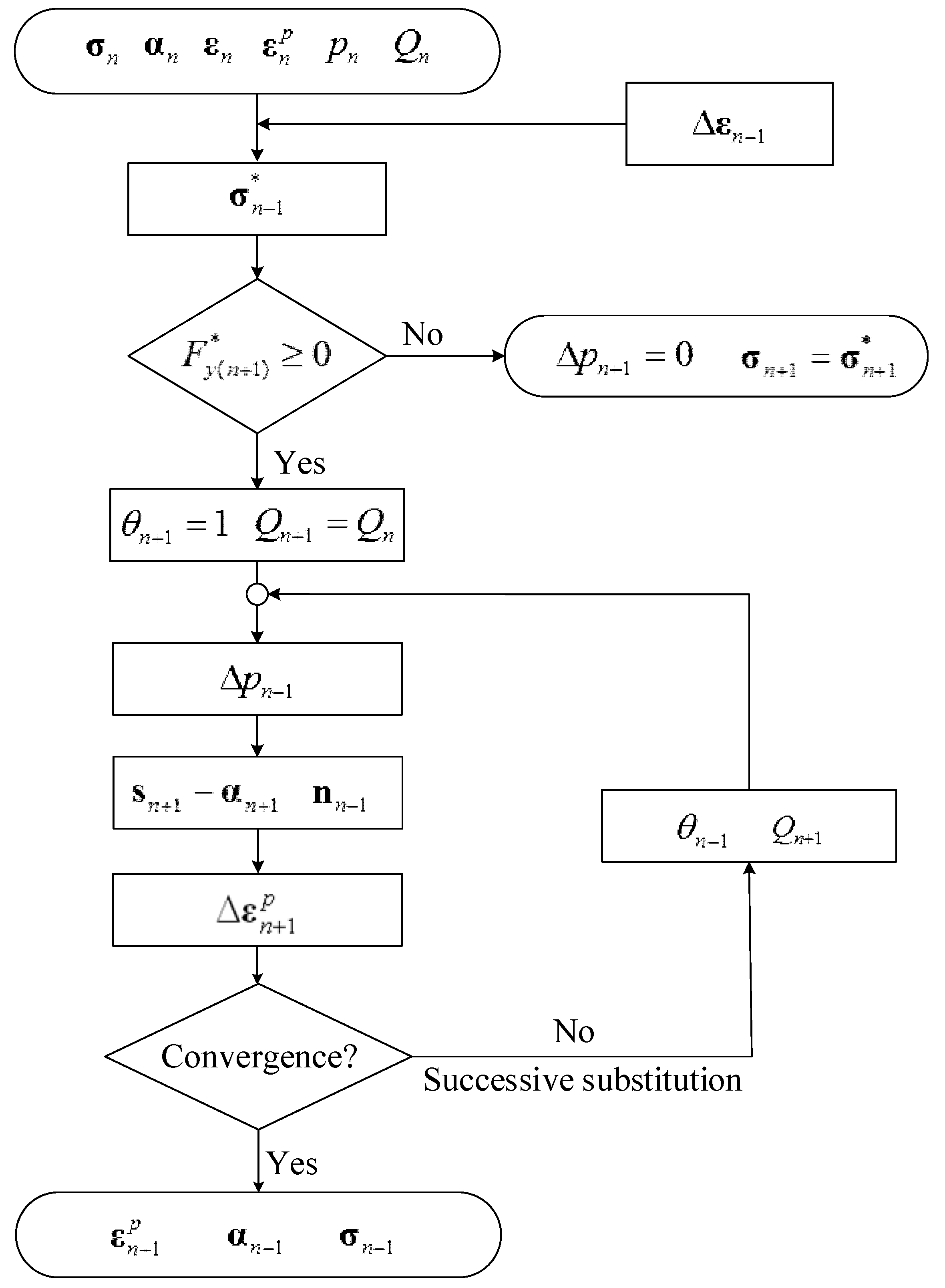
Figure 3.
Flow diagram of stress integration algorithm.
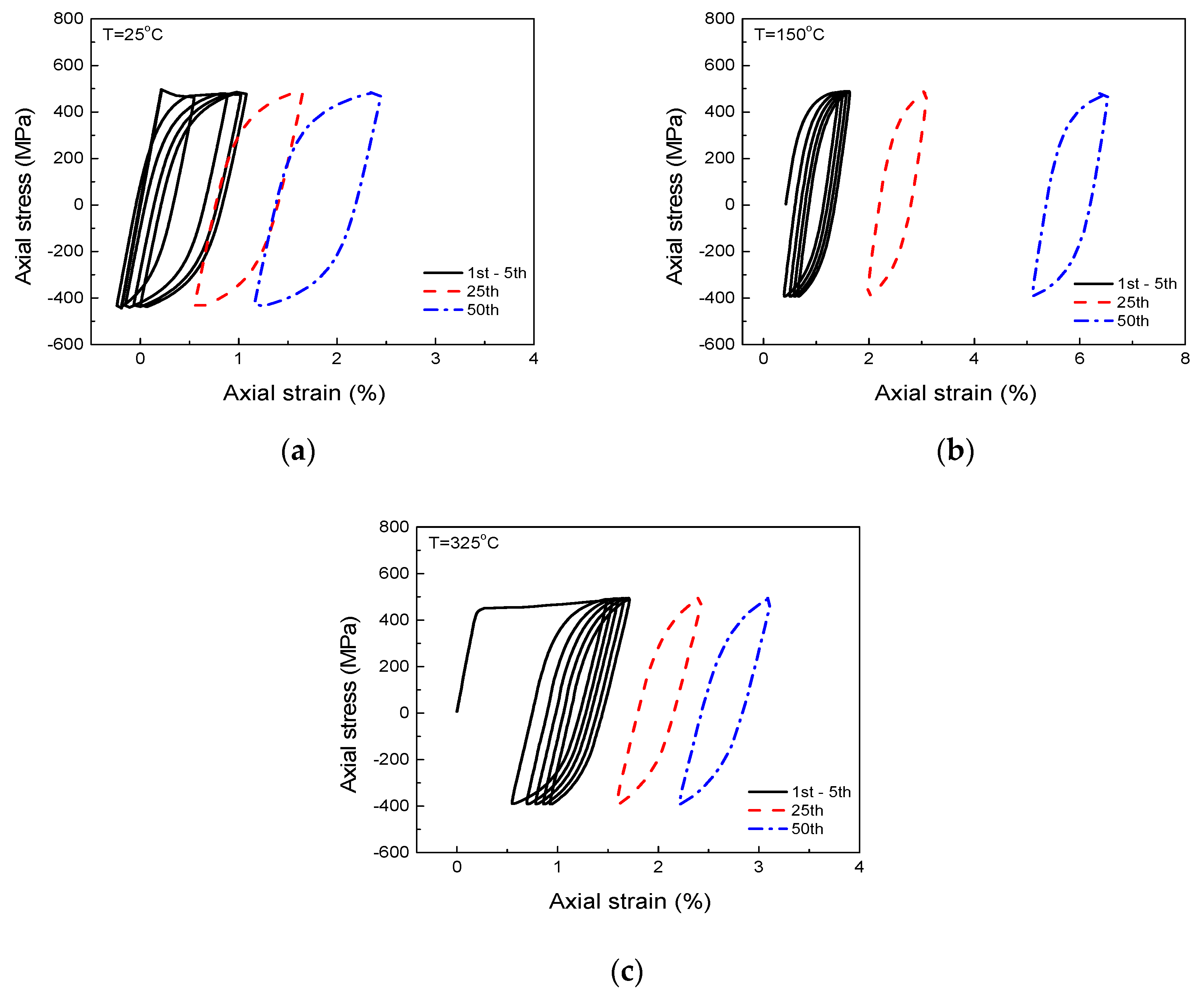
Figure 4.
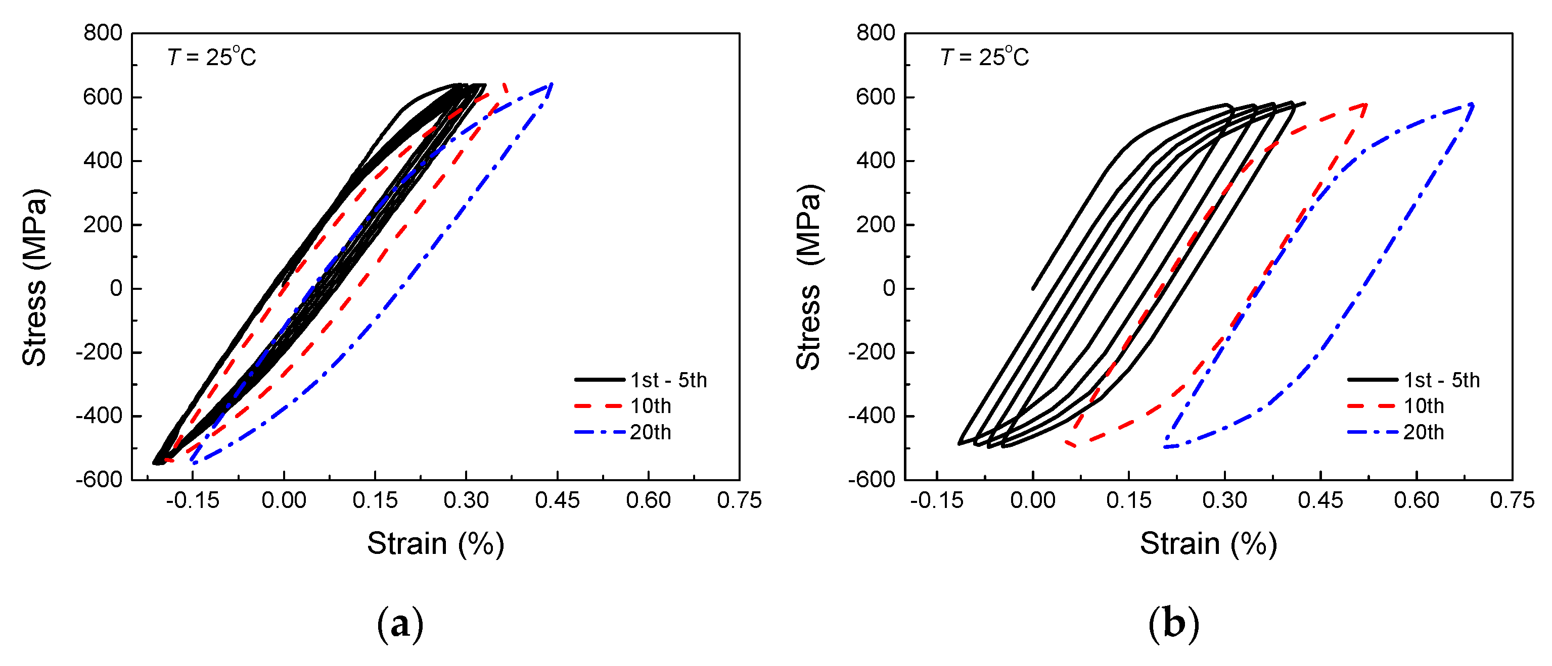
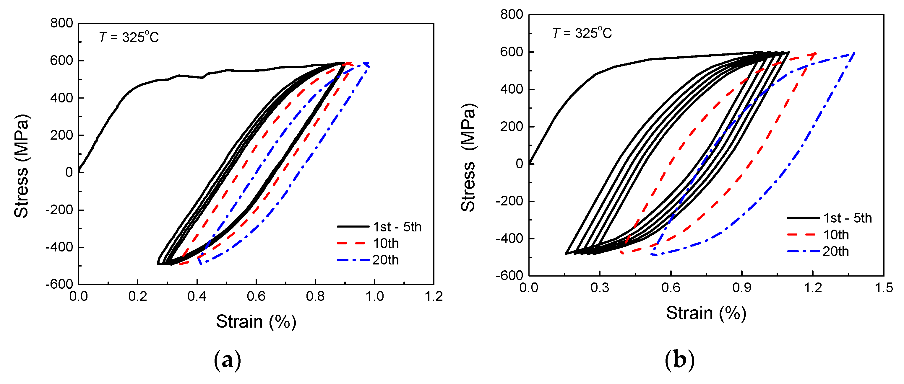
Experimental stress-strain curves under stress-controlled cycling at (a) 25 °C, (b) 150 °C and (c) 325 °C.
Figure 5.
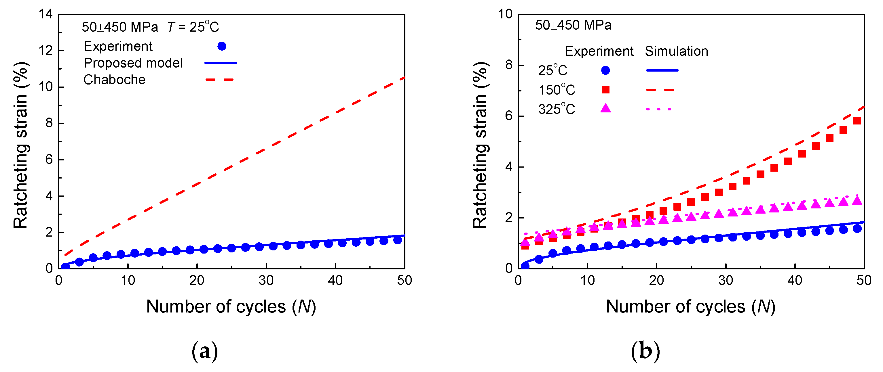
Comparisons between experimental and simulated ratcheting strain by: (a) Chaboche model and the proposed model at 25 °C; (b) the proposed model at different temperatures.
Figure 6.
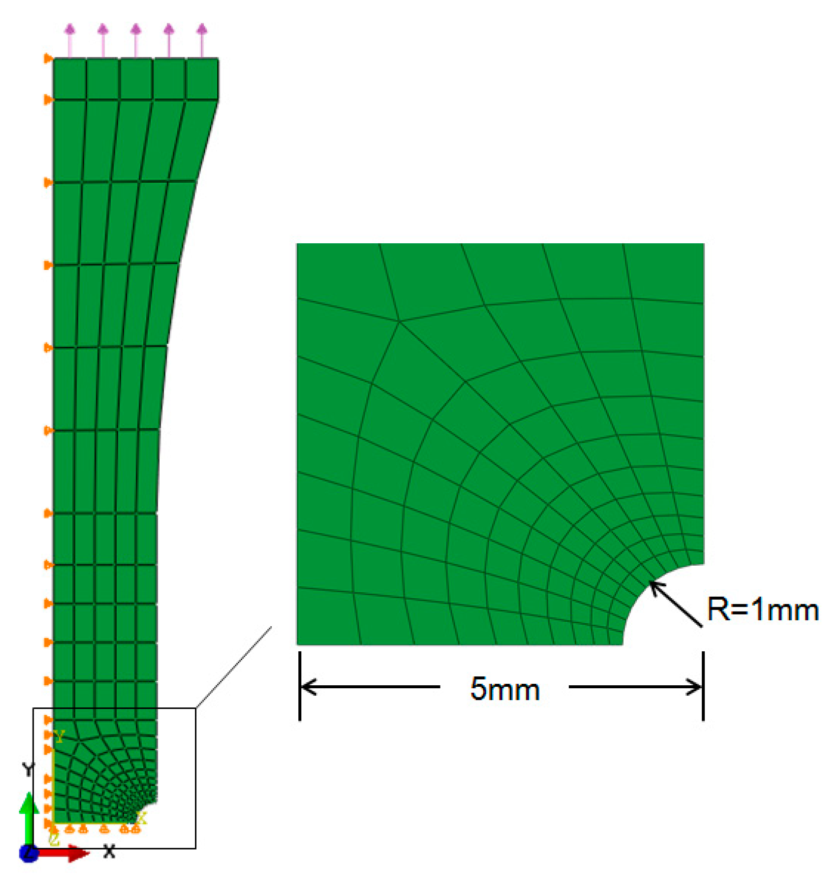
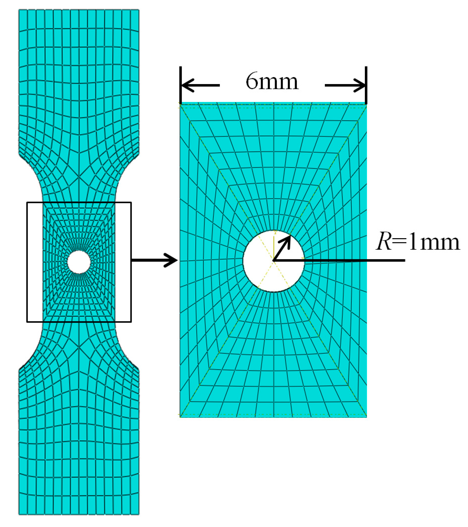
Axi-symmetrical finite element model of the notched bar.
Figure 7.
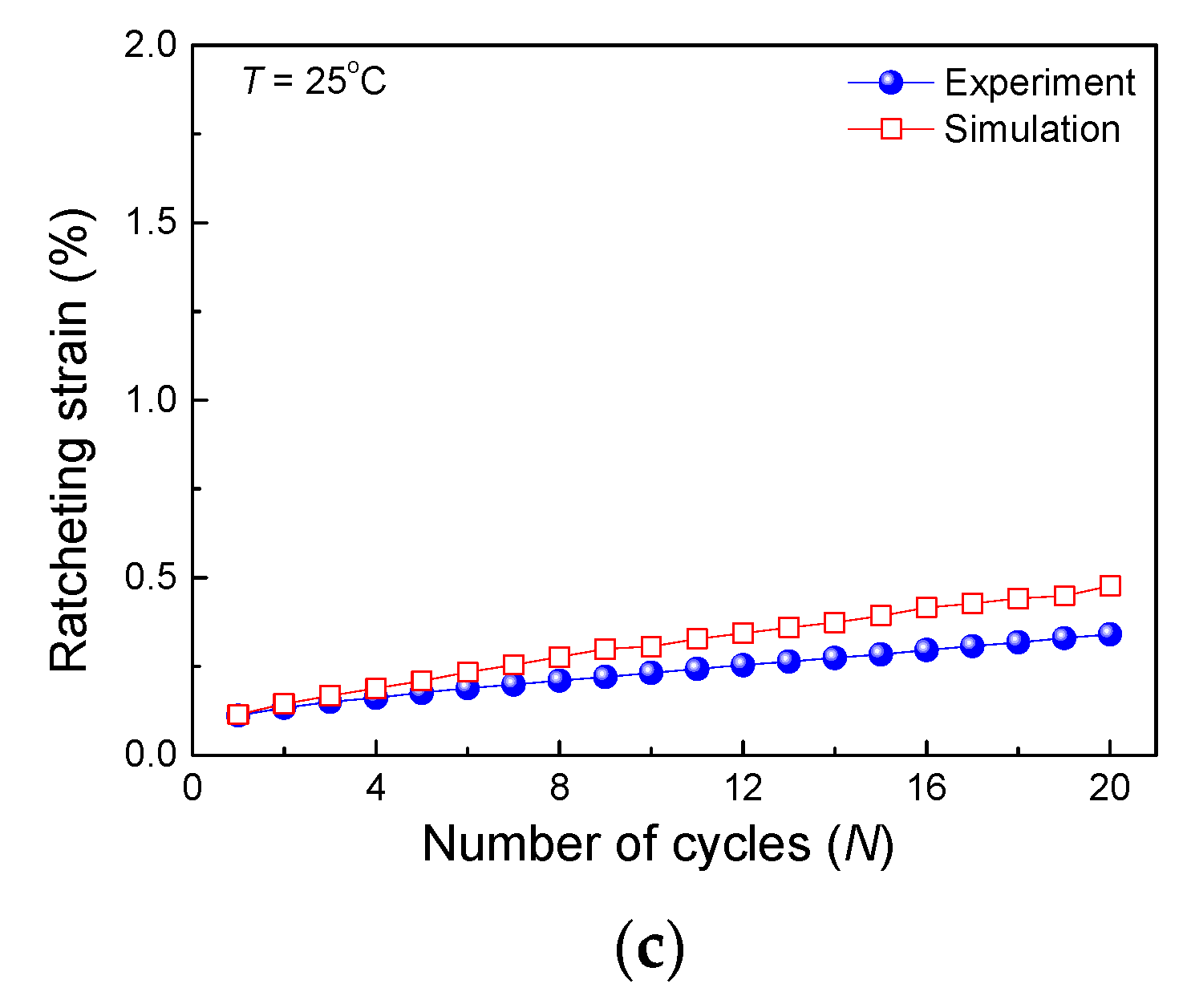
Results of the notched bar at 25 °C: (a) experimental stress-strain curves, (b) simulated stress-strain curves and (c) experimental and simulated ratcheting strains versus number of cycles.
Figure 8.
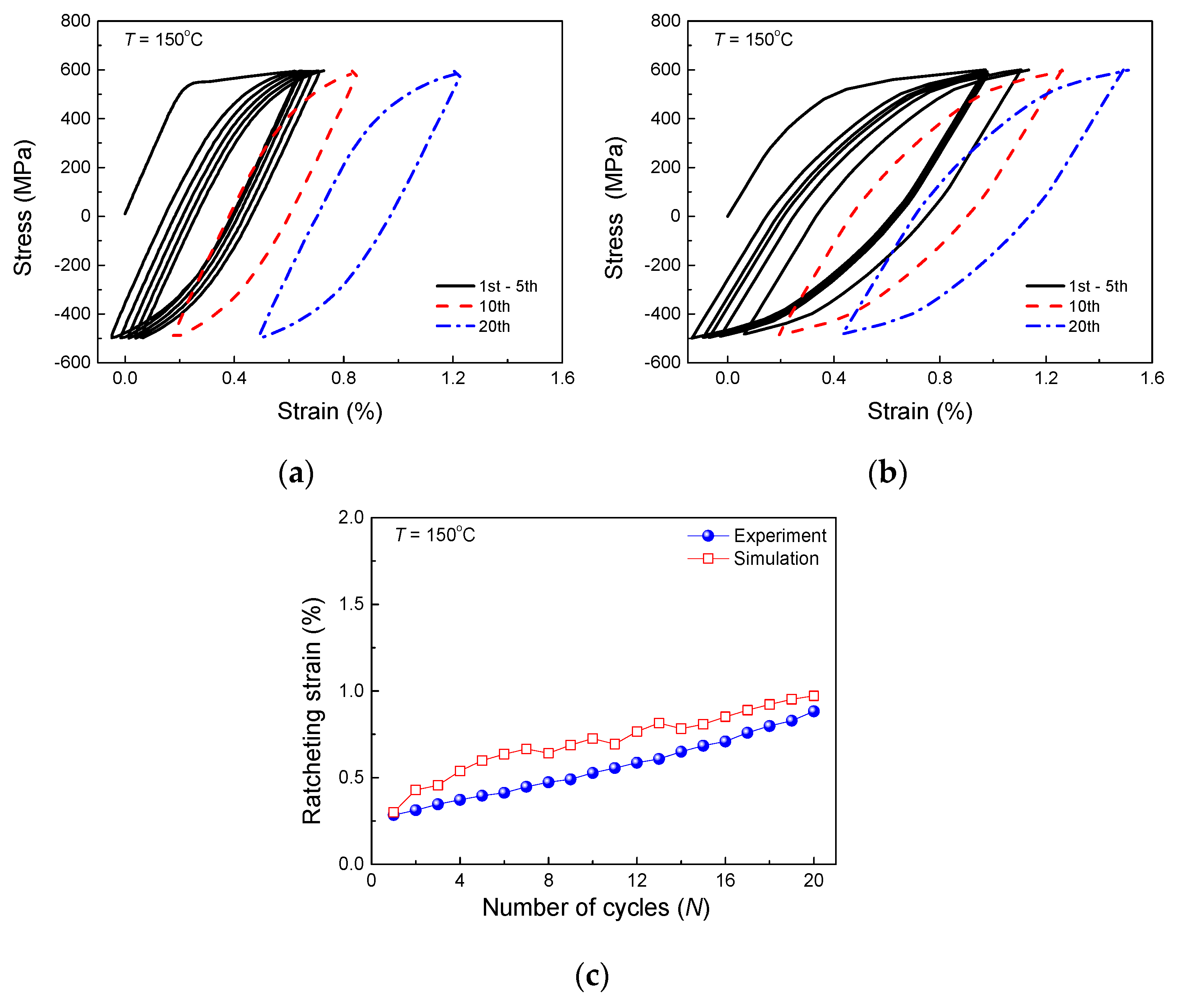
Results of the notched bar at 150 °C: (a) experimental stress-strain curves, (b) simulated stress-strain curves and (c) experimental and simulated ratcheting strains versus number of cycles.
Figure 9.
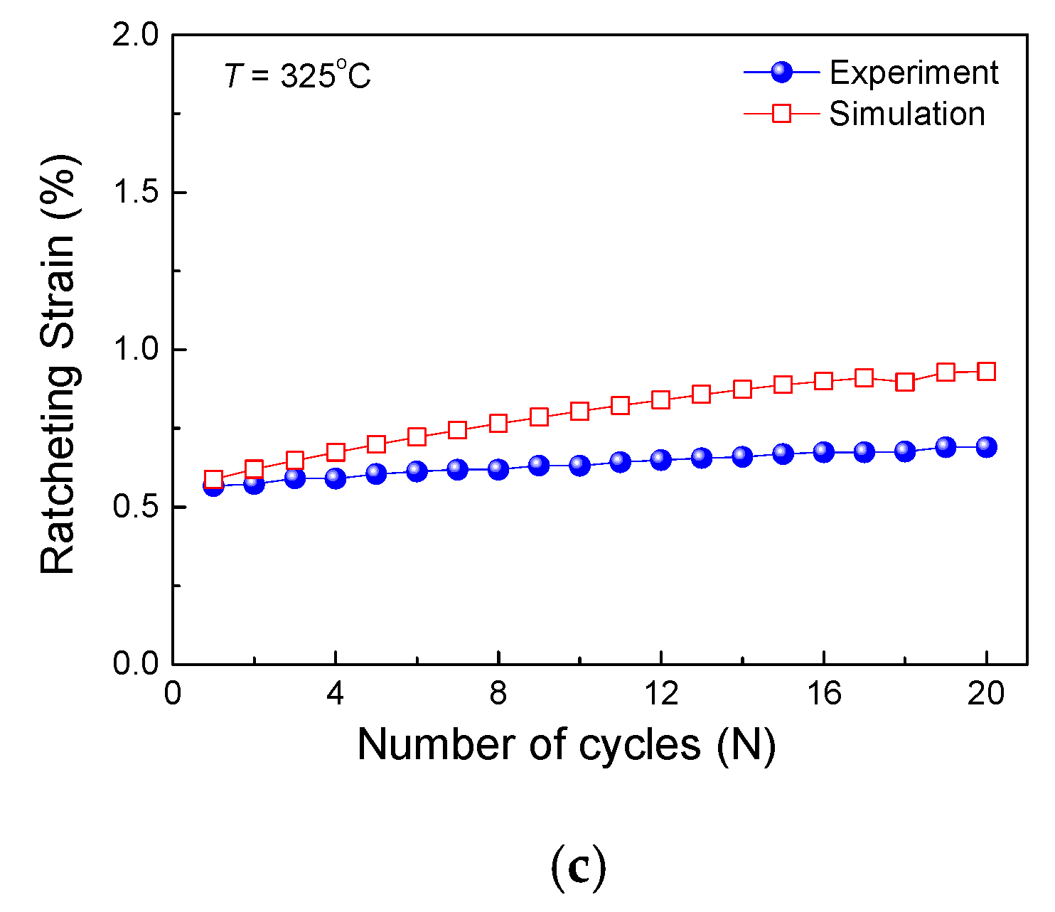
Results of the notched bar at 325 °C: (a) experimental stress-strain curves, (b) simulated stress-strain curves and (c) experimental and simulated ratcheting strains versus number of cycles.
Figure 10.
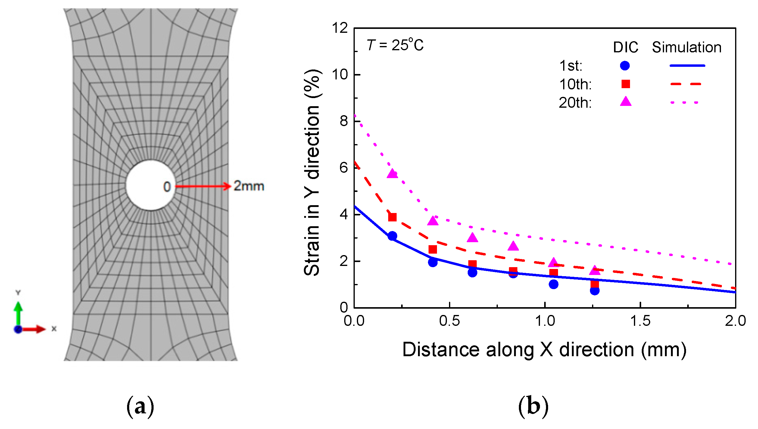
Finite element model of the plate with a center hole.
Figure 11.
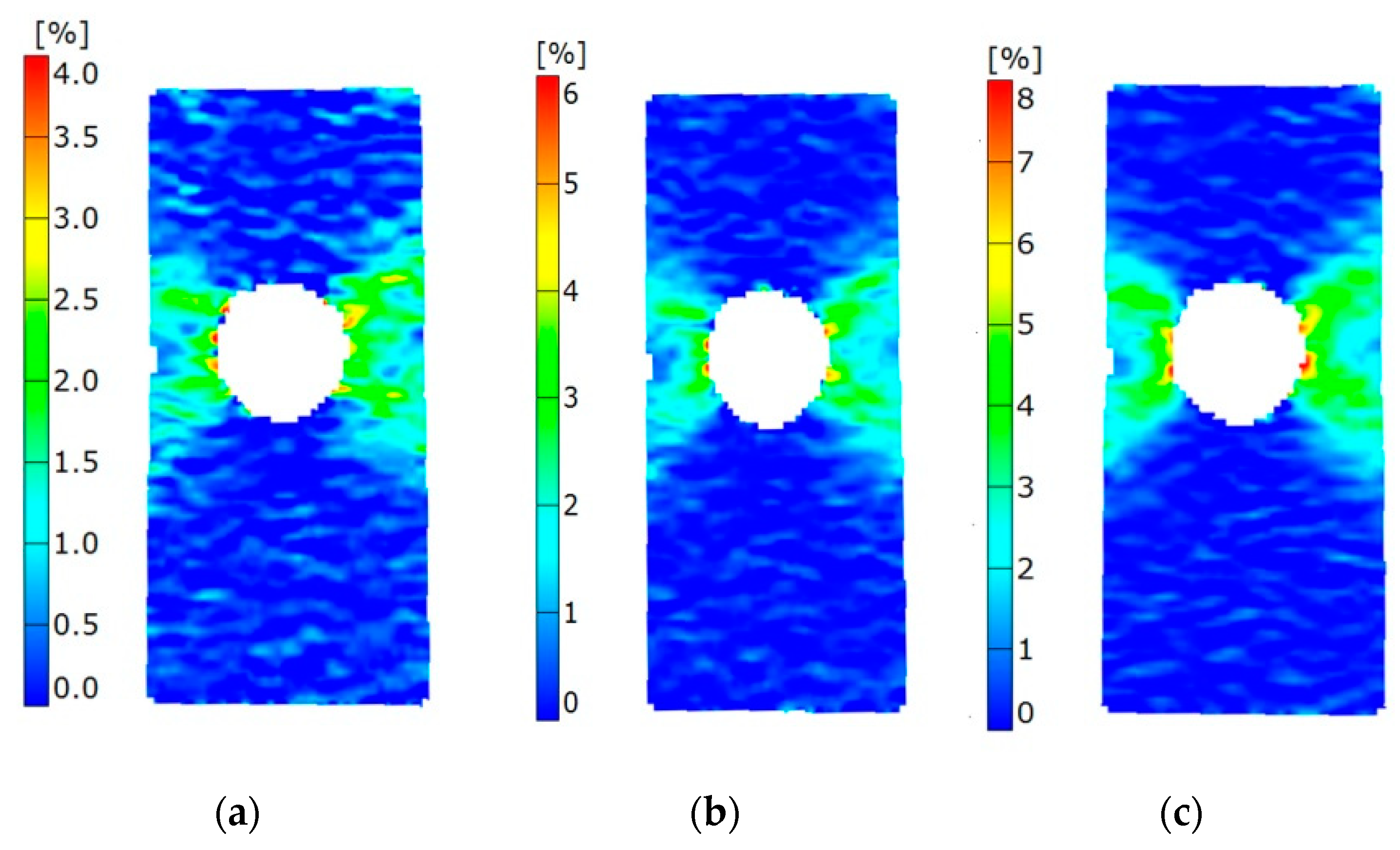
Experimental strain fields along the loading direction measured by the DIC technology in the (a) 1st cycle, (b) 10th cycle and (c) 20th cycle.
Figure 12.
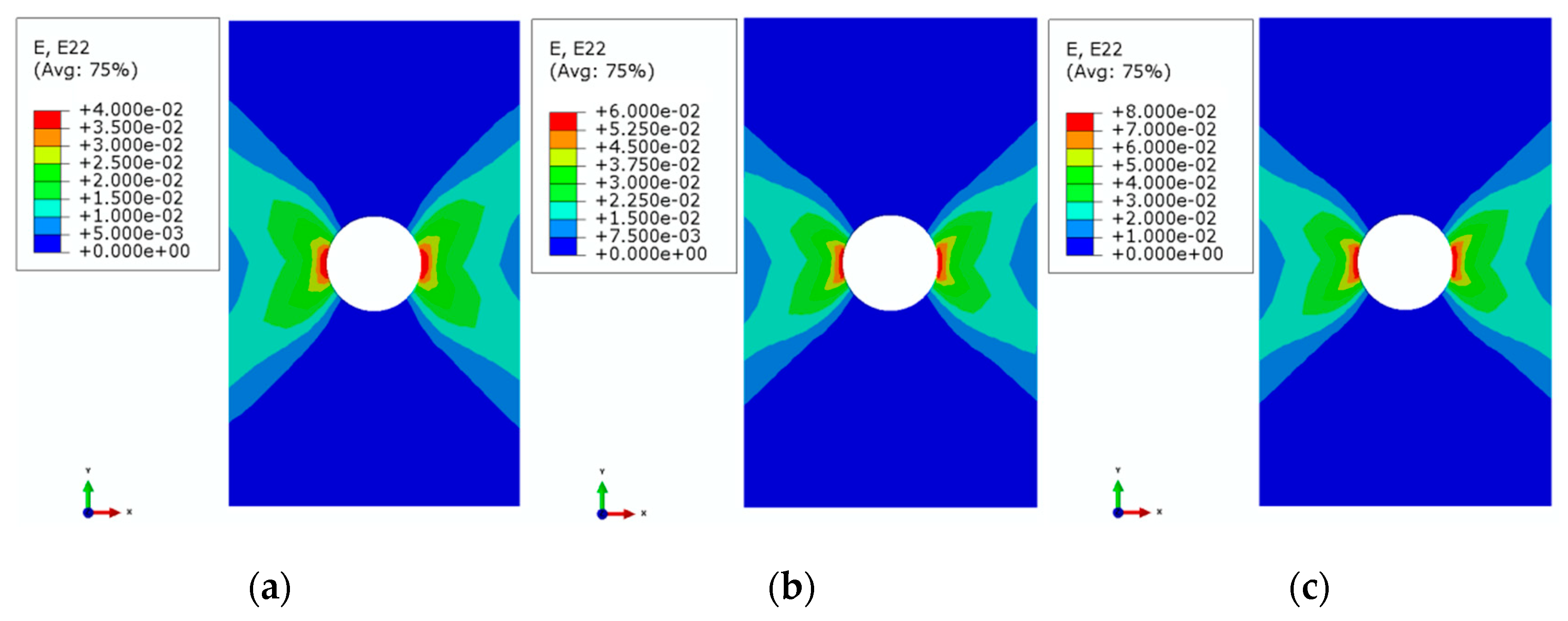
Simulated strain fields in the (a) 1st cycle, (b) 10th cycle and (c) 20th cycle.
Figure 13.
Comparison between the simulated results and measured ones by the DIC technology: (a) evaluated path location; (b) curves of strain in Y direction versus distance along X direction at different temperatures.
Table 1.
Material parameters using in the proposed model at different temperatures.
| Temperature /°C | Material Parameters |
|---|
| 25 | E = 2.23e5 MPa, ν = 0.3, a = 8.52, b = −1.0, c = −319, r = 5,
Q0 = 445 MPa, Q1= 447 MPa, Qsa = 410 MPa, γ = 0.6 |
| 150 | E = 2.0e5 MPa, ν = 0.3, a = 8.49, b = −4.29, c = −384.5, r = 5,
Q0 = 435 MPa, Q1= 428 MPa, Qsa = 395.6 MPa, γ = 0.6 |
| 325 | E = 2.0e5 MPa, ν = 0.3, a = 8.435, b = 0.5, c = −388.5, r = 5,
Q0 = 410 MPa, Q1= 412.6 MPa, Qsa = 413 MPa, γ = 0.3 |
© 2018 by the authors. Licensee MDPI, Basel, Switzerland. This article is an open access article distributed under the terms and conditions of the Creative Commons Attribution (CC BY) license (http://creativecommons.org/licenses/by/4.0/).


