Article

The Role of Retained Austenite and Its Carbon Concentration on Elongation of Low Temperature Bainitic Steels at Different Austenitising Temperature

The State Key Laboratory for Refractories and Metallurgy, Hubei Collaborative Innovation Center on Advanced Steels, International Research Institute for Steel Technology, Wuhan University of Science and Technology, Wuhan 430081, China
*
Authors to whom correspondence should be addressed.
Metals 2018, 8(11), 931; https://doi.org/10.3390/met8110931
Submission received: 25 October 2018 / Revised: 5 November 2018 / Accepted: 7 November 2018 / Published: 11 November 2018

Abstract

:
The influence of austenitising temperature on the tensile properties of low temperature bainitic steel was investigated. With the increasing austenitising temperature, a significant change of elongation was found between 850 and 950 °C, which was changed from 1.0 ± 0.5 to 10.7 ± 2.0%; while there was a slight increase between 950 to 1050 °C (11.2 ± 1.5%). By characterising the retained austenite at necking and matrix, we found that the elongation is obviously correlated with the retained austenite content, and also determined by the volume change of retained austenite during the tensile test. The transformation induced plasticity (TRIP) effect, which contributes to the improve elongation, almost did not occur at 850 °C due to the relatively low volume percentage of retained austenite and its high carbon concentration, which resulted in a very low martensite transformation temperature. With the austenitising, the temperature was increased up to 950 and 1050 °C, and a large volume percentage of retained austenite was observed in the matrix. Meanwhile, a considerable amount of retained austenite has occurred by the TRIP effect because of a moderate carbon content.

1. Introduction

Bainitic steels are a kind of steel used in armor, bearing, and wear-resistant plates owing to their ultra-high strength, good ductility, and toughness properties [1,2]. The microstructure of bainitic steel contains a mixture of fine bainitic ferrite plates, retained austenite, and some martensite [3,4]. The strength is mainly determined by bainitic ferrite (harder phase) and its dislocation density; and the ductility is controlled by the retained austenite, which is a softer phase compared with bainitic ferrite and martensite [5,6]. It is believed that the retained austenite stability is closely related to the ductility of the bainitic steel.
Retained austenite with a different stability contributes to the transformation induced plasticity (TRIP) effect at different strain stages until necking or damage occurs. In a previous work, the retained austenite stability was observed to be influenced by its chemical composition [4,7]. It is found that the carbon concentration in retained austenite has the strongest influence on the ductility of bainitic steel. The film-like retained austenite, which promotes the elongation in the TRIP steel, are more stable, and less likely to transform into martensite, because of their relatively high carbon content [8]. However, it was also demonstrated that too stable austenite does not guarantee better ductility, since it is difficult to transform into martensite under stress [4]. On the other hand, the TRIP effect will easily occur under small stress due to lower stability of retained austenite, which is also not conducive to the improvement of ductility.
More recently, it confirmed that the retained austenite stability also strongly depends on the size of the austenite grain [9,10]. In general, the size of the austenite grain will increase with the increasing of the austenitising temperature. It has been suggested that the size of the austenite grain has an optimal range for the improvement of the TRIP effect, and too large or too fine grains are not conducive to the mechanical property enhancement [9]. Researchers also found that the prior austenite grain size has a substantial contribution to the austenite stability when the austenite grain size is submicron [11]. However, it is discovered that there is no correlation between the mechanical stability of austenite and the grain size, the thermal stability of austenite increases significantly through grain refinement in stainless steel [12]. The most advantageous variants are selected in the TRIP effect to release tensile strain and leads to the grain size independence of the mechanical stability of austenite. Therefore, the relationship between the austenite grain size and retained austenite stability is not the same in different steels.
The aim of this study is to explore the retained austenite content and its carbon concentration influence on the elongation of low temperature bainitic steels treated at different austenitising temperatures. In addition, the variation of retained austenite volume fraction and its carbon concentration at the necking area is also investigated.

2. Experiment

The chemical analysis of the investigated steel is presented in Table 1. In the present work, the use of medium carbon steel as an experimental steel is necessary. The reason is that the high carbon content in the matrix will form a large number of Fe-C clusters, which is extremely detrimental to the plasticity of the low-temperature bainite steel [13,14]. In contrast, low carbon content reduces the stability of retained austenite, which is also not conducive to the improvement of plasticity. The as-received steel was homogenized at 1200 °C for two days in a vacuum furnace followed by slow cooling to an ambient temperature. The slow cooling rate to an ambient temperature was applied to avoid spontaneous crack formation due to the martensite transformation. The homogenized specimens were austenitized at 850 °C, 950 °C, and 1050 °C for 30 min, and then were isothermally transformed to bainite at 220 °C for 10 days. Finally, the specimens were air cooled to room temperature.
Quantitative XRD (X-ray diffraction) analysis (Rigaku D/Max-1200X diffractometer, Tokyo, Japan) was used to determine the volume percentage of retained austenite and its carbon concentration. Grinding and final polishing were carried out and the samples were etched in 4 vol.% nital solution for the phase characterization. The samples were set in the Bragg-Brentano configuration using a Rigaku D/Max-1200X diffractometer (Tokyo, Japan) with unfiltered Co Kα radiation (wavelength 1.78901 Å). The 2θ scanning angles were kept between 20° and 120° and the scanning speed was less than 0.1°/min. The machine was operated at 40 kV and 30 mA. The retained austenite volume percentage was calculated from the integrated intensities of (200), (220), and (311) austenite peaks and (200) and (211) of ferrite peaks [15,16]. The carbon content of retained austenite was measured using the lattice parameter and empirical equation [17], expressed as:
aγ/Å = 3.578 + 0.044Xc
where aγ represents the lattice parameters of austenite, and Xc is the weight percent of the carbon atom.
Cylindrical tensile samples with 5 mm in diameter and 25 mm in gauge length were machined in the longitudinal direction of bars. The tensile experiment were conducted with a 100 kN load cell using an Zwick HTM 5020 (ZWICK/ROELL, Ulm, Germany) fitted with a crosshead speed of 0.03 mm/s at ambient temperature. The specimens were extracted from the tensile fracture to the matrix at every 2 mm thickness. A total of five pieces, numbered a–e, were obtained as shown in Figure 1. These thin slices were used to characterize the microstructure and to measure the retained austenite content and its carbon concentration at the necking zone after the tensile test.
To measure the carbon concentration of retained austenite (RA), electron probe microanalysis (EPMA, JXA-8530F, JEOL, Tokyo, Japan) was also used, and its X-ray detector has a lower content limit of 0.001%. The operation and precautions have been reported in detail in an earlier work [18]. The carbon content of the measured point was determined at 15.0 kV and 20 mA. Every sample was assigned 30 points to detect the carbon concentration of RA, and then the average value of the carbon content was calculated.
The microstructural features of the matrix and austenite grain size were determined by using optical microscopy. The surfaces of tensile fractured specimens were observed by a scanning electron microscope. A transmission electron microscope (TEM, JEM-2100, JEOL, Tokyo, Japan) was utilized to measure the thickness of bainite ferrite with at least 10 micrographs. The austenite grain size was measured by the linear intercept method with the data obtained from different fields of the samples [19]. The Vickers hardness tests (THV-1MD) were noted as an average of at least 15 indentations using a load of 1 Kg.

3. Results

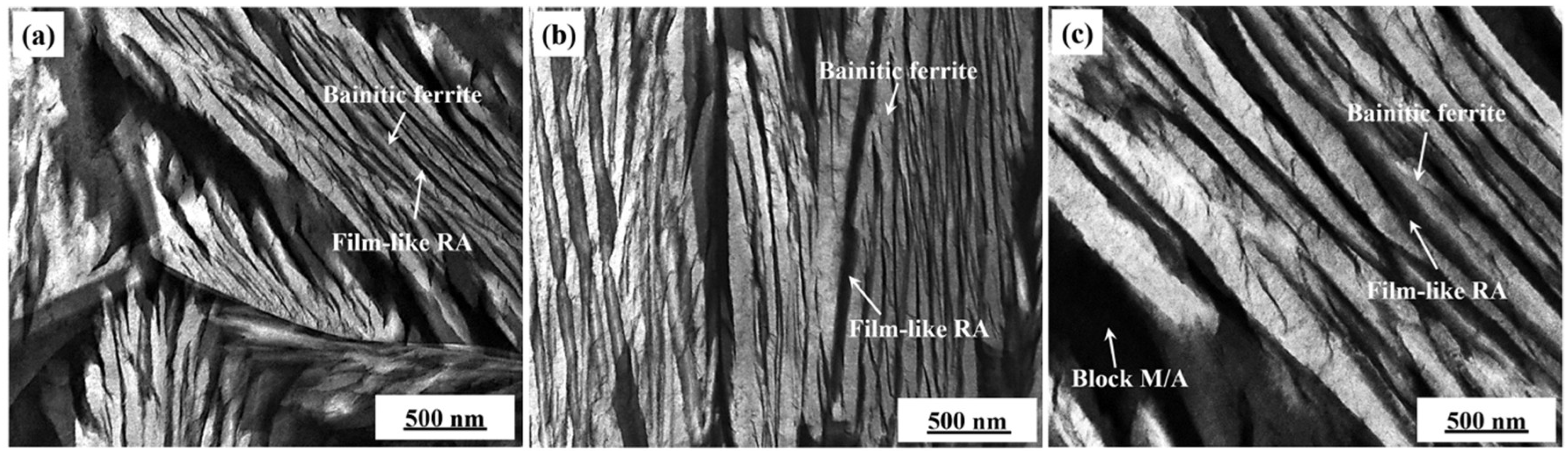
3.1. Microstructural Analysis

The typical microstructure as resolved by optical microscope (OM) and scanning electron microscope (SEM) micrographs of the steel after austenitising at 850, 950, and 1050 °C for 30 min and then isothermally at 220 °C for 10 days is given in Figure 2. In Figure 2a–c, bainitic ferrite (dark phase), retained austenite (light phase), and a small part of martensite can be seen in the three types of bainitic steels. The microstructure became much coarser with an increasing austenitising temperature. This feature reduces the nucleation density of bainitic ferrite and increases the needle length of the bainite lath, since the austenite grain size is greater at a higher austenitising temperature. Retained austenite is divided into two forms in low temperature bainitic steel, namely film-like retained austenite distributed between the bainitic ferrite lath, and blocky retained austenite distributed between bainite sheaves. At a much higher SEM magnification, the retained austenite, in a blocky shape, can clearly be seen, while there was no sign of a film-like structure (Figure 2d–f). It has been observed that fine film-like retained austenite can be obtained through bainite transformation at a low temperature (220 °C). Figure 3 shows the TEM micrographs treated at different austenitising temperatures. The measured thickness of bainitic ferrite was 45 ± 5 nm, 50 ± 5 nm, and 70 ± 15 nm for the specimens treated at 850 °C, 950 °C, and 1050 °C, respectively, which showed an upward trend with the austenitising temperature.

3.2. Tensile Properties

The tensile strength, elongation, and hardness of the tested steels by three different austenitising treatments are shown in Table 2. The hardness decreased gradually with the increasing austenitising temperature. There was a slight difference in the tensile strength at 850 °C and 950 °C, but it decreased sharply from 1900 ± 60 MPa at 950 °C to 1794 ± 65 MPa at 1050 °C. For elongation, there is a marked increase between 850 °C and 950 °C, which was increased from 1.0 ± 0.5% to 10.7 ± 2.0%; while the elongation at 1050 °C (10.7 ± 2.0) has a slight increase compared to 950 °C (11.2 ± 1.5%).
Figure 4 displays the tensile fractography of the tensile specimens at different austenitising temperatures. The fracture surface at 850 °C (Figure 4a) consists of large quasi-cleavage facets and an intergranular fracture, indicating a brittle fracture mode. The fracture surface with different size dimples at 950 °C is shown in Figure 4b, which indicates a better toughness in comparison to that illustrated in Figure 4a. Austenitising at 1050 °C (Figure 4c) resulted in an extremely high density of dimples, indicating a typical ductile mode of fracture. It can be deduced that a higher austenitising temperature produces a positive effect on improving elongation.

3.3. The Austenite Grain Size at Different Austenitising Temperatures

Optical micrographs (OM) of the austenite grain boundaries are presented in Figure 5a–c. Obviously, the fine austenite grain can be obtained when austenitising temperature at 850 °C and 950 °C. The austenite grain size was measured using the linear intercept method. The austenite grain is coarsened due to an increase in the austenitising temperature. The average austenite grain size, compared with that at 850 °C (33 ± 8 μm) and 950 °C (35 ± 6 μm), was significantly larger at 1050 °C (82 ± 11 μm), while only a little difference was seen between 850 °C and 950 °C (Figure 5d).

3.4. The Retained Austenite Contents of Necking Sites at Different Austenitising Temperatures

Representative XRD patterns (Figure 6a–c) confirmed the volume percentage of retained austenite dependence of necking sites. All test specimens were consisted of bainitic ferrite, martensite, and retained austenite. With the necking sites from a–e, the volume fractions of the retained austenite were increased with approaching to site e (Figure 7a). It is evident from site e that the volume percentage of the retained austenite of 850 °C (11.68%) is slightly higher than that of 950 (11.15%) and 1050 °C (11.22%). However, from the investigation of site a, the retained austenite content at 850 °C (8.70%) was significantly higher compared with that at 950 (4.52%) and 1050 °C (4.06%), indicating that only a small part of the retained austenite was transformed into martensite during the tensile process for 850 °C. The three straight lines represent the trend of the content of retained austenite with necking sites at different austenitising temperatures after linear fitting. The carbon concentration of retained austenite at different necking sites are shown in Figure 7b. The experimental results show that the carbon concentration in the retained austenite of different necking sites is similar to that of the matrix. This means that the tensile process has essentially no obvious impact on the carbon concentration in the retained austenite.

4. Discussion

Figure 5d presents the variation of austenite grain size dependence of austenitising temperatures. Austenite grain size slightly increased as the temperature increased from 850 °C to 950 °C, while it rapidly increased from 950 °C to 1050 °C. There exists a critical temperature (about 1000 °C), below which it is not significant and above which is a distinct temperature effect. The growth of the austenite grain depends on the rates of the austenite grain boundary migration [20]. With the increase of the austenitising temperature, the migration rate of the grain boundary is also accelerated. Below this critical austenitising temperature the migration rate is slightly increased (essentially unchanged), while above this temperature it is significantly increased. The sudden change in grain growth behavior at 950 °C and 1050 °C may be attributed to the dissolution of the pinning particles of MnS. The pinning force produced by MnS was gradually decreased at higher austenitising temperatures due to spherical sulfides (Figure 8). The statistical results showed that the aspect ratio of MnS are 2.65 ± 1.11, 2.21 ± 0.67, and 1.69 ± 0.41 at 850 °C, 950 °C, and 1050 °C, respectively. It has been suggested that large and long string MnS inclusions are more significantly effective in hindering the migration of austenite grain boundaries than spherical ones [21]. In addition, the relationship between elongation and MnS has been investigated according to the McClintock mode [22]:
dσ/(σ·dE) < KF2 (f/1 − f) (2λ + 1)1/2
where σ is the true stress, f is the volume fraction of inclusions, λ is the aspect ratio of inclusions, K is a constant, F is a hole-growth factor, and dσ/dE is the work-hardening rate. In the present work, f can be regarded as a constant at 850 °C, 950 °C, and 1050 °C since the volume fraction of MnS having nearly the same value (5.42 wt.%), which was calculated by JMatpro (V7.0, Sente Software, Boston, UK). According to the model, the decrease in the aspect ratio of MnS causes the shear bands’ formation to be more difficult at the same volume fraction of MnS (f), thereby resulting in a higher elongation during the tensile process. Table 2 showed that the tensile strength presents a downward trend with the increase of austenite grain size. Similar experimental results have been reported in other high-strength steels [23,24,25]. It suggested that the tensile strength gradually decreases due to a coarser austenite grain with the austenitising temperature increasing.
In addition, the tensile strength is also affected by the size of bainitic ferrite. The size of the austenite grain has a significant impact on the length, width, and thickness of bainite ferrite by affecting the density of nucleation sites and growth rate. It has been proved that the thickness of bainitic ferrite in the coarse austenite grain is larger than that of finer ones [26]. In low temperature bainitic steel, the tensile strength is mainly determined by the thickness of the bainitic ferrite. The measured thickness of bainitic ferrite (45 ± 5 nm, 50 ± 5 nm, and 70 ± 15 nm for the specimens treated at 850 °C, 950 °C, and 1050 °C, respectively) showed that the specimen treated at 1050 °C had the largest thickness. Therefore, it had lower tensile strength at higher austenitising temperatures (1050 °C) due to its coarse bainitic ferrite plates.
The tensile elongation depends on the content of retained austenite, which is a softer phase compared with the bainitic ferrite and martensite [2,5]. The XRD test was performed to estimate the volume percentage of retained austenite and its carbon concentration. It is suggested that the retained austenite percentage of the matrix can be expected to increase with an increase in the austenitising temperature (Table 3). As the austenitising temperature increased from 850 °C to 950 °C, the volume percentage of retained austenite increased from 12.07% to 16.23%, while there was only a little increase between 950 °C and 1050 °C. In low temperature bainitic steel, the content of retained austenite is a significant factor for controlling elongation. Thus, the sample has poor elongation at 850 °C compared with that at 950 °C and 1050 °C, which was caused by the lesser content of retained austenite (12.07%).
Further enhancement in the elongation can be achieved when the retained austenite transforms to martensite because of the TRIP effect. To make the TRIP effect fully effective, a suitable stability of retained austenite is necessary. The chemical composition is one of the most critical aspects influencing the retained austenite stability, especially the carbon concentration [27]. There are two conditions that are disadvantageous for improving the elongation of bainitic steel. The first is that the retained austenite is too stable to cause a TRIP effect because of the high carbon concentration. Secondly, a low carbon content causes low stability of the retained austenite so that the TRIP effect occurs under lower stress. Thus, it is meaningful to measure the carbon concentration in retained austenite to identify stability (Table 3). The carbon content at 850 °C is 1.553 ± 0.085% and the corresponding elongation is only 1.0 ± 0.5%, while the carbon content is 1.275 ± 0.070% at 950 °C and 1.250 ± 0.090% at 1050 °C, which correspond to the elongation rates of 10.7 ± 2.0% and 11.2 ± 1.5%, respectively. Owing to the higher carbon concentration in retained austenite at 850 °C, the transformation to martensite also cannot occur at the same stress compared with that at 950 °C and 1050 °C. This result was also proved by changing the retained austenite content at the fracture necking. As shown in Figure 7a, the change of retained austenite content at 850 °C is significantly less than that at 950 °C and 1050 °C. The retained austenite content of 850 °C is 8.70% and 12.07% at the site a and the matrix, respectively. It means that only 3.37% of the retained austenite transforms into martensite at site a. The difference of the retained austenite content between the fracture and the matrix at 950 °C and 1050 °C indicated that a large volume percentage of retained austenite has almost entirely transformed into martensite during the tensile test. The content of the retained austenite, which has transformed into martensite (site a), reached 11.71% and 12.62% at 950 °C and 1050 °C, respectively. Compared with 850 °C, the TRIP effect of 950 °C and 1050 °C is stronger. Therefore, the quantity of retained austenite that caused the TRIP effect is also determined by its stability.
To further explore the plastic deformation at different necking sites, the local tensile elongation was also investigated with the rule of constant volume in plastic deformation (Figure 9). It can be expressed as: L % = ( R s 2 / R N 2 1 ) × 100 % . Rs and RN represent the radius of the sample before the tensile test and the radius of the necking site after the test, respectively. The results showed that the local tensile elongation decreases with the distance away from the fracture. It also demonstrated that it has a negative correlation with the content of retained austenite at the same necking sites.
Except for carbon concentration in retained austenite, the retained austenite stability can also be demonstrated by its martensite transformation temperature, Ms. It is more difficult to transform retained austenite into martensite if the Ms is too low. As the alloying elements except carbon were homogeneously distributed during isothermal treatment, the Ms of the retained austenite can be calculated by the following equation [28,29]:
Ms (°C) = 539 − 423C − 30.4Mn − 7.5Si + 30Al (wt.%)
According to Equation (3) and the experimental result of EPMA (Table 4), the Ms temperatures of the retained austenite were −197 °C, −79 °C, and −69 °C for the samples treated at 850, 950, and 1050 °C, respectively. Therefore, the retained austenite at the 850 °C specimen is more stable than that of the 950 °C and 1050 °C specimens. Excessively stable retained austenite does not induce martensite transformation during the tensile process, and thus does not contribute to elongation.
In this work, it has been proved that the elongation is a combined effect of retained austenite content and its carbon concentration. In the meantime, the Ms of the retained austenite also influences its stability and thus plays a role on the elongation.

5. Conclusions

Tensile tests were performed on low temperature bainitic steel treated at different austenitising temperatures. The characteristics of the microstructures and the factors causing the difference in tensile properties were also discussed. Conclusions are drawn as follows:
(1)
In the necking area, the retained austenite content increased with the distance away from the fracture at three different austenitising temperatures. At 850 °C, the content of retained austenite at the fracture is significantly higher than that at 950 °C and 1050 °C, while the content of it transformed into martensite is lower during the tensile test.
(2)
The elongation is a combination function of the volume percentage of retained austenite and its carbon concentration. The TRIP effect makes a great contribution in improving the elongation at 950 °C and 1050 °C, owing to a higher volume percentage of retained austenite and its appropriate carbon concentration.
(3)
When the austenitising temperature is 850 °C, the retained austenite has an extremely low Ms temperature. This proved that the too stable retained austenite cannot play a positive effect on the elongation.

Author Contributions

Conceptualization, B.D., T.H. and K.W.; Methodology, B.D.; Software, B.D. and G.Z.; Validation, K.W., T.H. and B.D.; Formal Analysis, B.D. and W.Z.; Investigation, B.D. and W.Z.; Resources, K.W.; Data Curation, B.D.; Writing—Original Draft Preparation, B.D.; Writing—Review & Editing, T.H., K.W. and G.Z.; Visualization, B.D.; Supervision, K.W.; Project Administration, K.W.; Funding Acquisition, K.W.

Funding

The authors sincerely thank the support from the Major Technology Innovation of Hubei Province (No. 2016AAA022), the National Natural Science Foundation of China (No. U1532268), and the Hubei Provincial Natural Science Foundation of Innovation Team (No. 2016CFA004).

Conflicts of Interest

The authors declare no conflict of interest.

References

  1. Bhadeshia, H.K.D.H. High performance bainitic steels. Mater. Sci. Forum. 2005, 500, 63–74. [Google Scholar] [CrossRef]
  2. Bhadeshia, H.K.D.H. Nanostructured Bainite. In Proceedings of the Royal Society of London A: Mathematical, Physical and Engineering Sciences, London, UK, 8 January 2010. [Google Scholar]
  3. Garcia-Mateo, C.; Paul, G.; Somani, M.; Porter, D.; Bracke, L. Transferring nanoscale bainite concept to lower C contents: A perspective. Metals 2017, 7, 159. [Google Scholar] [CrossRef]
  4. Garcia-Mateo, C.; Caballero, F.G. The role of retained austenite on tensile properties of steels with bainitic microstructures. Mater. Trans. 2005, 46, 1839–1846. [Google Scholar] [CrossRef]
  5. Jacques, P.; Delannay, F.; Cornet, X.; Harlet, P.; Ladriere, J. Enhancement of the mechanical properties of a low-carbon, low-silicon steel by formation of a multiphased microstructure containing retained austenite. Metall. Mater. Trans. A 1998, 29, 2383–2393. [Google Scholar] [CrossRef]
  6. Hasan, H.S.; Peet, M.J.; Avettand-Fènoë, M.N.; Bhadeshia, H.K.D.H. Effect of tempering upon the tensile properties of a nanostructured bainitic steel. Mater. Sci. Eng. A 2014, 615, 340–347. [Google Scholar] [CrossRef]
  7. Garcia-Mateo, C.; Caballero, F.G.; Chao, J.; Capdevila, C.; Andres, C.G.D. Mechanical stability of retained austenite during plastic deformation of super high strength carbide free bainitic steels. J. Mater. Sci. 2009, 44, 4617–4624. [Google Scholar] [CrossRef] [Green Version]
  8. Bhadeshia, H.K.D.H.; Edmonds, D.V. The bainite transformation in a silicon steel. Mater. Trans. A 1979, 10, 895–907. [Google Scholar] [CrossRef]
  9. Wang, J.; Zwaag, S.V.D. Stabilization mechanisms of retained austenite in transformation-induced plasticity steel. Metall. Mater. Trans. A 2001, 32, 1527–1539. [Google Scholar] [CrossRef]
  10. Jimenez-Melero, E.; Dijk, N.H.V.; Zhao, L.; Sietsma, J.; Offerman, S.E.; Wright, J.P.; Zwaag, S.V.D. Characterization of individual retained austenite grains and their stability in low-alloyed TRIP steels. Acta Mater. 2007, 55, 6713–6723. [Google Scholar] [CrossRef]
  11. Lee, S.; Lee, S.J.; Cooman, B.C.D. Austenite stability of ultrafine-grained transformation-induced plasticity steel with Mn partitioning. Scr. Mater. 2011, 65, 225–228. [Google Scholar] [CrossRef]
  12. Matsuoka, Y.; Iwasaki, T.; Nakada, N.; Tsuchiyama, T.; Takaki, S. Effect of grain size on thermal and mechanical stability of austenite in metastable austenitic stainless steel. ISIJ. Int. 2013, 53, 1224–1230. [Google Scholar] [CrossRef]
  13. Hu, F.; Wu, K.M.; Hou, T.P.; Peter, H.; Rodionova, I.; Zhang, F.C. The effect of microphases on elongation of nanostructured bainitic steels. Metallurgist 2017, 60, 1295–1300. [Google Scholar]
  14. Rementeria, R.; Capdevila, C.; Domínguez-Reyes, R.; Poplawsky, J.D.; Guo, W. Carbon clustering in low-temperature bainite. Metall. Mater. Trans. A 2018, 49, 5277–5287. [Google Scholar] [CrossRef]
  15. Garcia-Mateo, C.; Peet, M.; Caballero, F.G.; Bhadeshia, H.K.D.H. Tempering of hard mixture of bainitic ferrite and austenite. Mater. Sci. Technol. 2013, 20, 814–818. [Google Scholar] [CrossRef]
  16. Caballero, F.G.; Bhadeshia, H.K.D.H.; Mawella, K.J.A.; Jones, D.G.; Brown, P. Very strong low temperature bainite. Mater. Sci. Technol. 2002, 18, 279–284. [Google Scholar] [CrossRef] [Green Version]
  17. Bhadeshia, H.K.D.H.; Edmonds, D.V. The mechanism of bainite formation in steels. Acta Metall. 1980, 28, 1265–1273. [Google Scholar] [CrossRef]
  18. Pinard, P.T.; Schwedt, A.; Ramazani, A.; Prahl, U.; Richter, S. Characterization of dual-phase steel microstructure by combined submicrometer EBSD and EPMA carbon measurements. Microsc. Microanal. 2013, 19, 996–1006. [Google Scholar] [CrossRef] [PubMed]
  19. Garcia-Mateo, C.; Jimenez, J.A.; Lopez-Ezquerra, B.; Rementeria, R.; Morales-Rivas, L.; Kunta, M.; Caballero, F.G. Analyzing the scale of the bainitic ferrite plates by XRD, SEM and TEM. Mater. Charact. 2016, 122, 83–89. [Google Scholar] [CrossRef] [Green Version]
  20. Zhang, Y.B.; Godfrey, A.; Liu, Q.; Liu, W.; Jensen, D.J. Analysis of the growth of individual grains during recrystallization in pure nickel. Acta Mater. 2009, 57, 2631–2639. [Google Scholar] [CrossRef]
  21. Guo, L.; Roelofs, H.; Lembke, M.I.; Bhadeshia, H.K.D.H. Effect of manganese sulphide particle shape on the pinning of grain boundary. Mater. Sci. Technol. 2017, 33, 1013–1018. [Google Scholar] [CrossRef]
  22. Biswas, D.K.; Venkatraman, M.; Narendranath, C.S.; Chatterjee, U.K. Influence of sulfide inclusion on ductility and fracture behavior of resulfurized HY-80 steel. Metall. Trans. A 1992, 23, 1479–1492. [Google Scholar] [CrossRef]
  23. Meysami, A.H.; Ghasemzadeh, R.; Seyedein, S.H.; Aboutalebi, M.R. An investigation on the microstructure and mechanical properties of direct-quenched and tempered AISI 4140 steel. Mater. Des. 2010, 31, 1570–1575. [Google Scholar] [CrossRef]
  24. Hou, H.; Qi, L.; Zhao, Y.H. Effect of austenitising temperature on the mechanical properties of high-strength maraging steel. Mater. Sci. Eng. A 2013, 587, 209–212. [Google Scholar] [CrossRef]
  25. Liu, F.; Lin, X.; Song, M.; Song, K. Austenitising behavior of laser solid formed ultrahigh-strength 300 M steel. Steel Res. Int. 2017, 88, 1600371. [Google Scholar] [CrossRef]
  26. Hu, F.; Hodgson, P.D.; Wu, K.M. Acceleration of the super bainite transformation through a coarse austenite grain size. Mater. Lett. 2014, 122, 240–243. [Google Scholar] [CrossRef]
  27. Jaques, P.J.; Girault, E.; Mertens, A.; Verlinden, B.; Delanny, F. The developments of cold-rolled TRIP-assisted multiphase steels. Low silicon TRIP-assisted multiphase steels. ISIJ. Int. 2001, 41, 1068–1074. [Google Scholar] [CrossRef]
  28. Xiong, X.C.; Chen, B.; Huang, M.X.; Wang, J.F.; Wang, L. The effect of morphology on the stability of retained austenite in a quenched and partitioned steel. Scr. Mater. 2013, 68, 321–324. [Google Scholar] [CrossRef]
  29. Mahieu, J.; Maki, J.; De-Cooman, B.C.; Claessens, S. Phase transformation and mechanical properties of Si-free CMnAl transformation-induced plasticity-aided steel. Metall. Mater. Trans. A 2002, 33, 2573–2580. [Google Scholar] [CrossRef]
Figure 1. (a) Tensile sample of experiment steels; (b) five slices at every 2 mm thickness, numbered through a to e, were obtained.
Metals 08 00931 g001
Figure 2. Optical micrographs (OM) and scanning electron microscope (SEM) images at different austenitising temperatures. (a) and (d) 850 °C; (b) and (e) 950 °C; (c) and (f) 1050 °C.
Metals 08 00931 g002
Figure 3. Transmission electron microscope (TEM) images treated at different austenitising temperatures. (a) 850 °C; (b) 950 °C; (c) 1050 °C.
Metals 08 00931 g003
Figure 4. The fracture morphology of specimens after the tensile test. (a) 850 °C; (b) 950 °C; and (c) 1050 °C.
Metals 08 00931 g004
Figure 5. The OM images of austenite grain of the steel at different austenitising temperatures for 30 min followed by isothermal transformation at 220 °C for 10 days. (a) 850 °C; (b) 950 °C; (c) 1050 °C; and (d) dependence of the austenite grain size on austenitising temperatures.
Metals 08 00931 g005
Figure 6. X-ray diffraction (XRD) patterns of retained austenite content at five necking sites at (a) 850 °C; (b) 950 °C; (c) 1050 °C, respectively. (d) The retained austenite content of matrix.
Metals 08 00931 g006
Figure 7. (a) The retained austenite contents of five necking sites and (b) its carbon content at different austenitising temperatures followed by numbering through a to e. Note that site a is close to the tensile fracture, and number e is close to the matrix.
Metals 08 00931 g007
Figure 8. MnS inclusions at different austenitizing temperatures of (a) 850 °C, (b) 950 °C, and (c) 1050 °C. The inset in the upper right represents the composition of MnS.
Metals 08 00931 g008
Figure 9. The local tensile elongation of five necking sites was calculated with the rule of constant volume in plastic deformation.
Metals 08 00931 g009
Table 1. Chemical composition of the investigated steel (wt.%).
CMnSiMoNiCoCrSFe
0.582.211.760.330.760.450.540.02balance
Table 2. Tensile properties of the investigated steel.
Austenitising Temperature (°C)Tensile Strength (MPa)Elongation (%)Hardness (HV)
8501910 ± 651.0 ± 0.5619 ± 10
9501900 ± 6010.7 ± 2.0599 ± 10
10501794 ± 6511.2 ± 1.5586 ± 5
Table 3. The volume percentage of retained austenite and its carbon concentration at different austenising temperatures.
Austenitising Temperature (°C)The Volume Fraction of Retained Austenite (%)The Carbon Content in Retained Austenite by XRD (wt.%)The Carbon Content in Retained Austenite by EPMA (wt.%)
85012.071.5101.553 ± 0.085
95016.231.2581.275 ± 0.070
105016.681.2471.250 ± 0.090
Table 4. The content of C, Mn, Si, and Al in retained austenite (wt.%) and its Ms at different austenising temperatures.
Austenitising Temperature (°C)CMnSiAlMs (°C)
8501.553 ± 0.0852.182 ± 0.0551.657 ± 0.050-−197
9501.275 ± 0.0702.186 ± 0.0801.662 ± 0.090-−79
10501.250 ± 0.0902.190 ± 0.0751.660 ± 0.065-−69

