Friction Stir Spot Welding-Brazing of Al and Hot-Dip Aluminized Ti Alloy with Zn Interlayer


Abstract
:
1. Introduction
2. Experimental
3. Results and Discussion
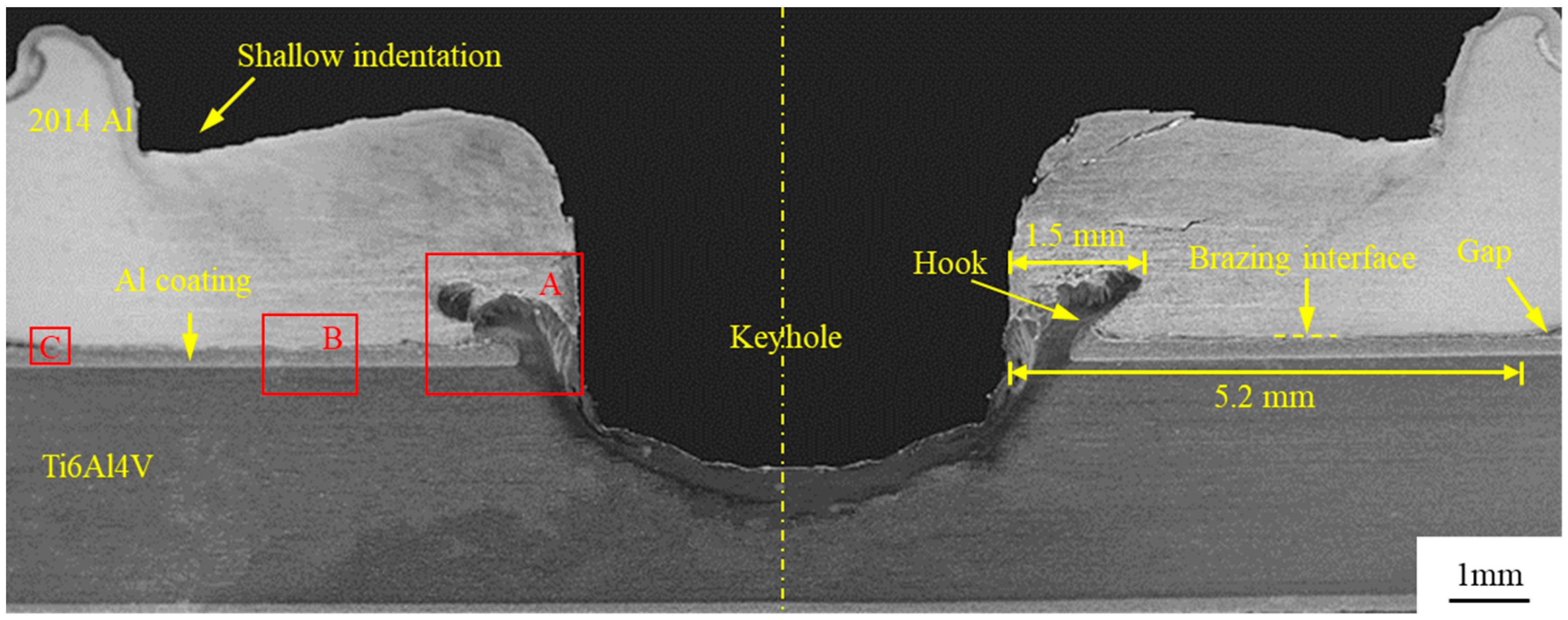
3.1. Macrostructure
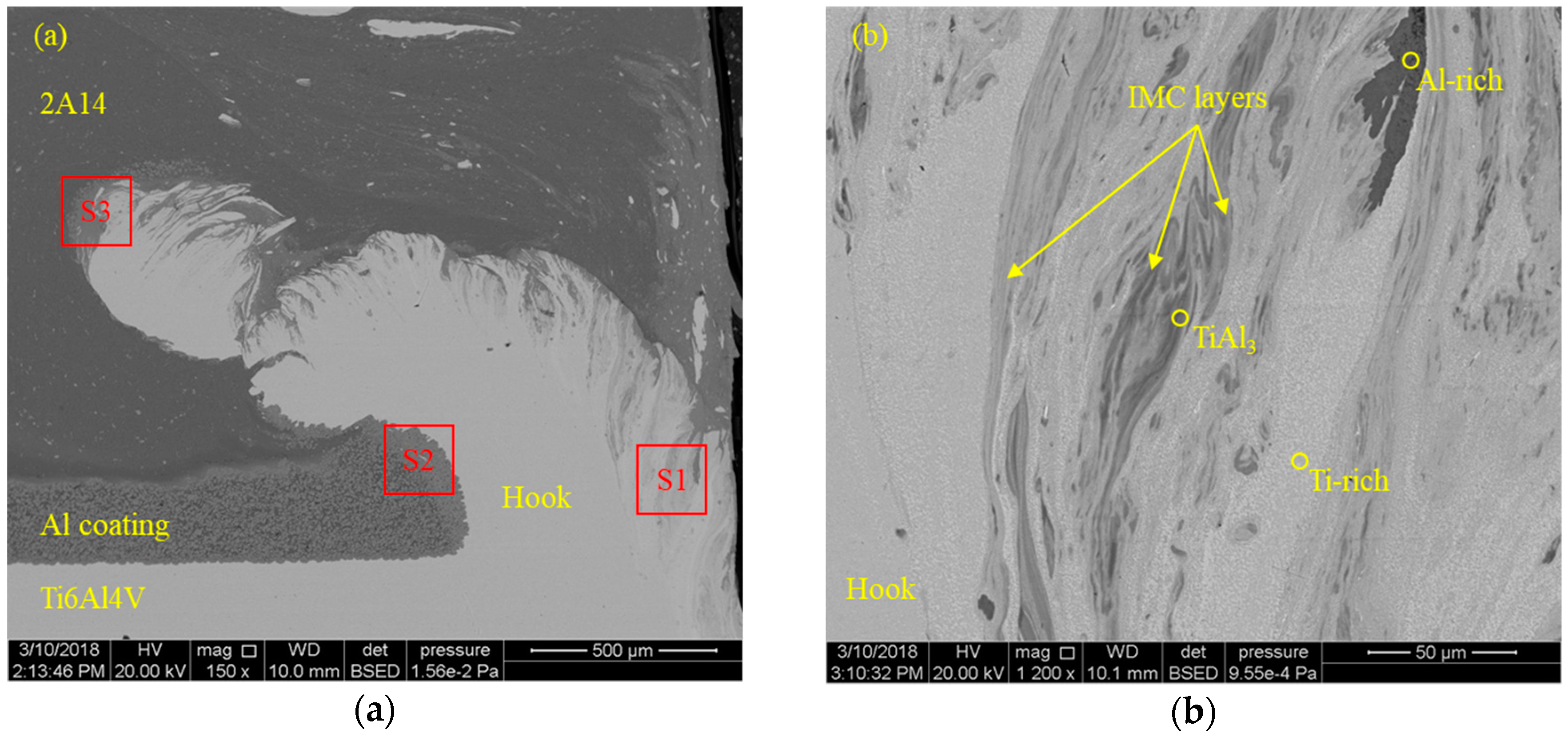
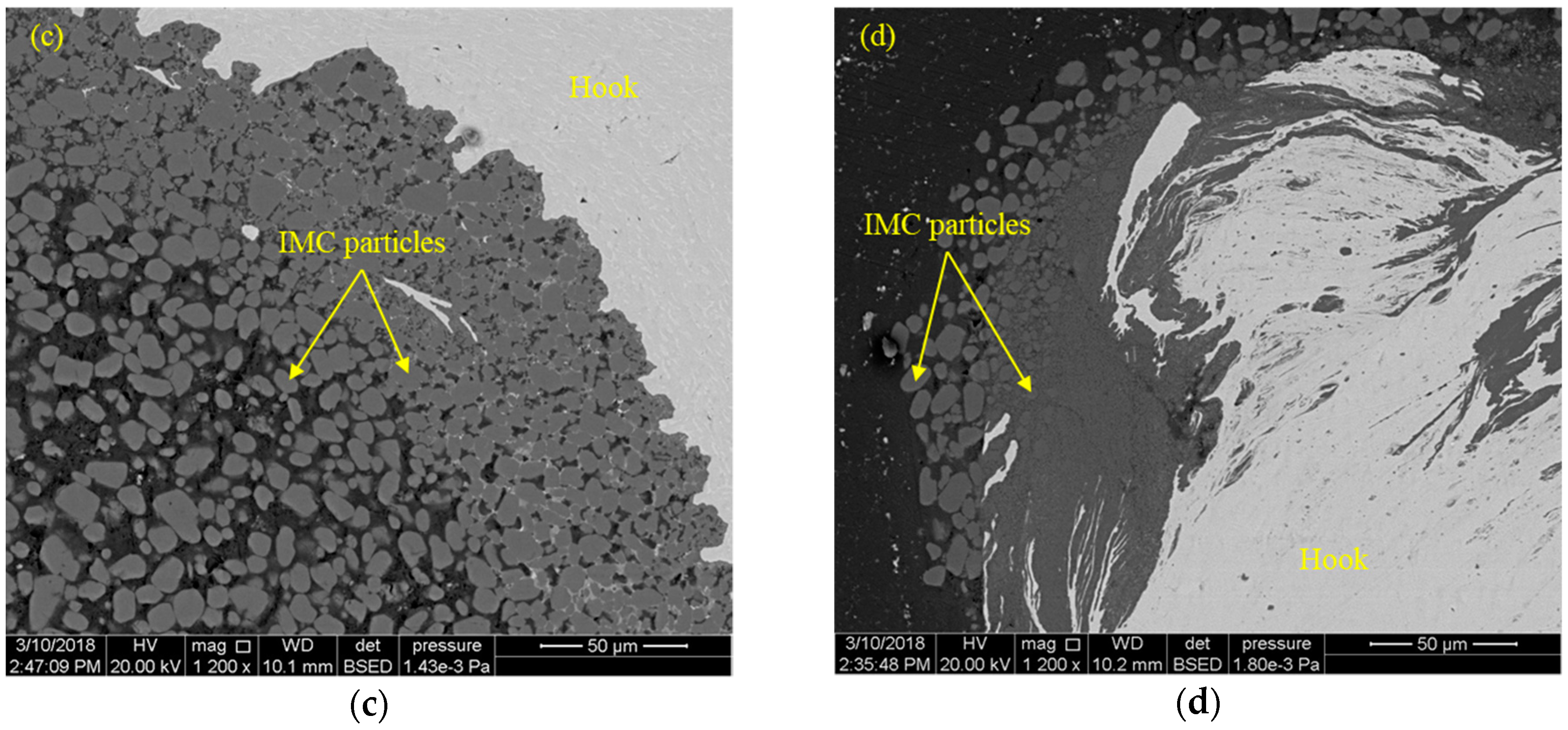
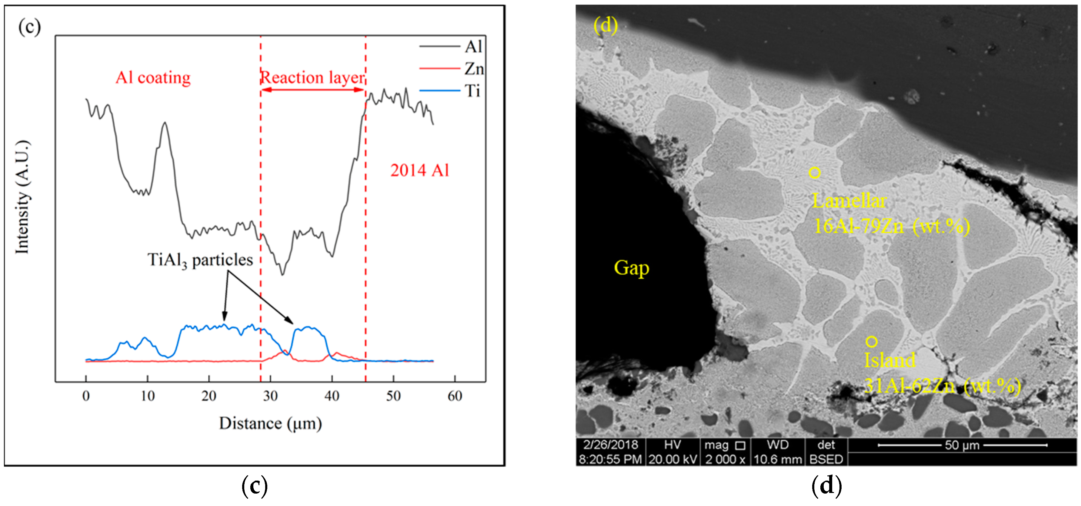
3.2. Microstructure
3.3. Mechanical Property
3.4. Parametric Study
4. Conclusions
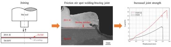
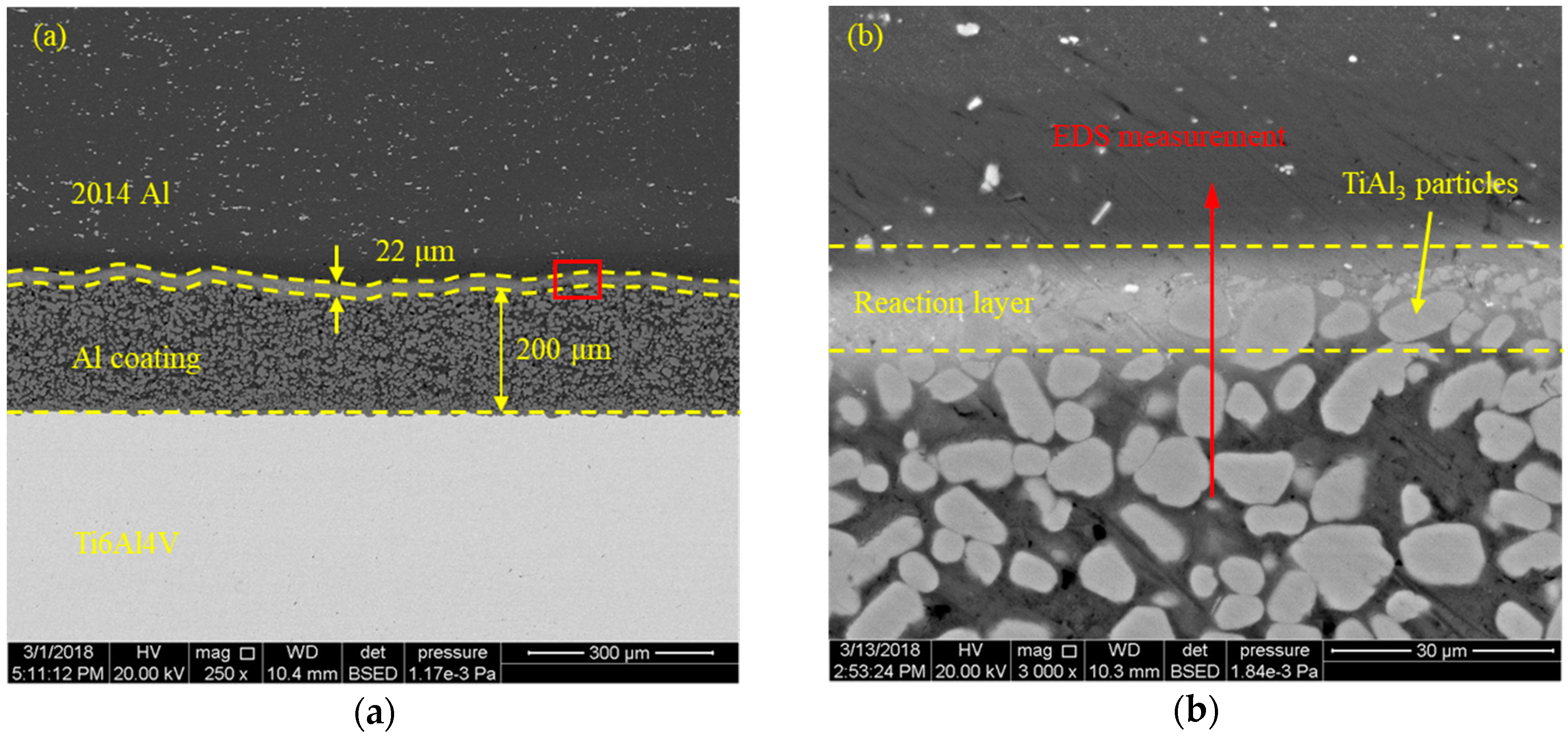
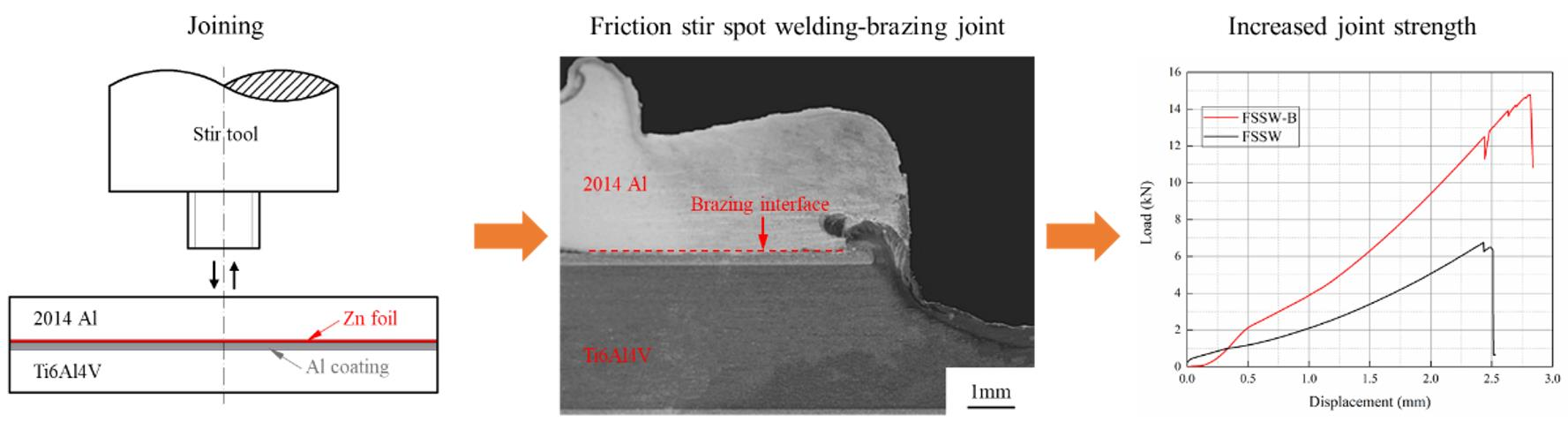
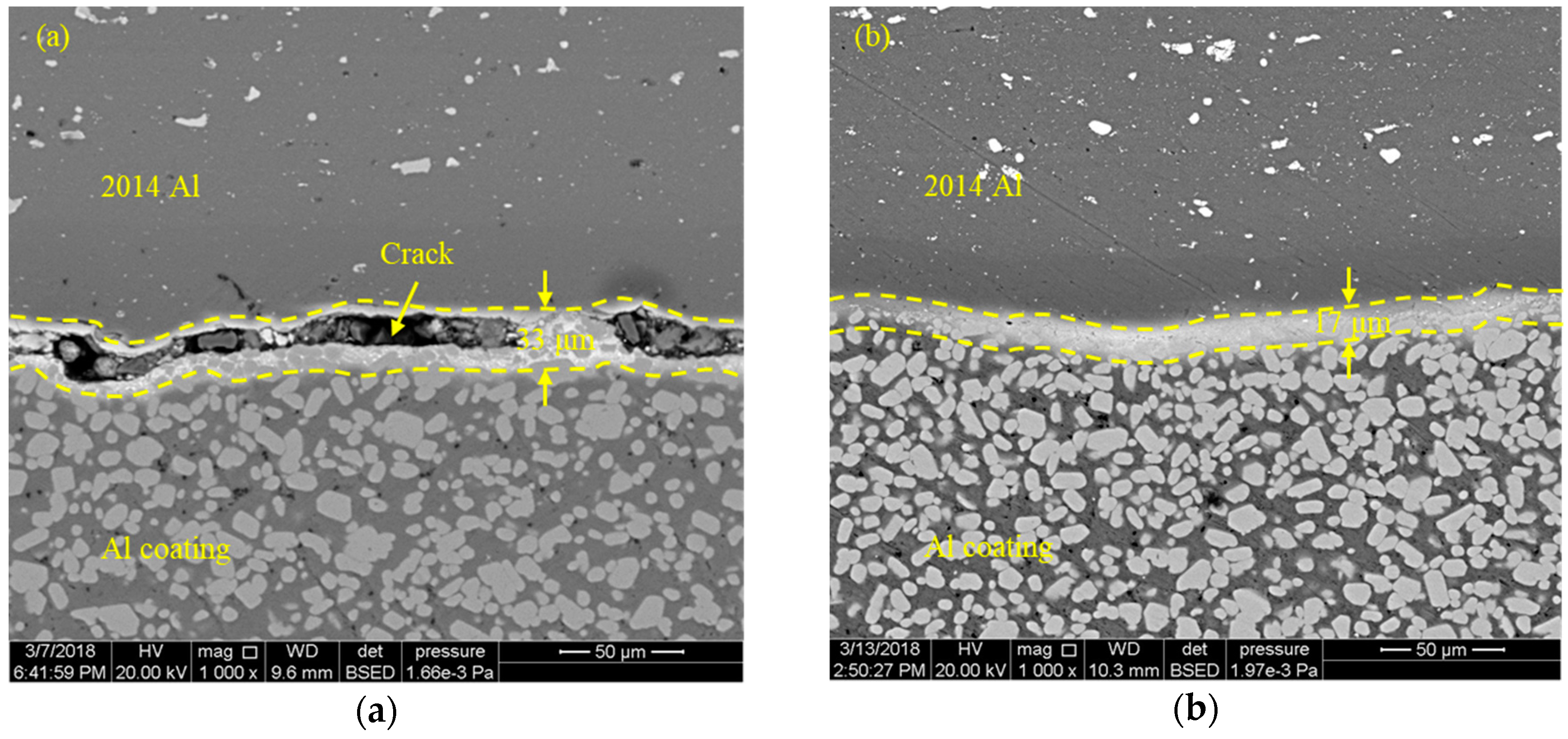
- In addition to the solid-state joining of 2014-T4 Al and Ti6Al4V alloys via the FSSW technique, brazing between the Al alloy and Al coating on Ti6Al4V alloy was successfully introduced by the addition of a Zn interlayer.
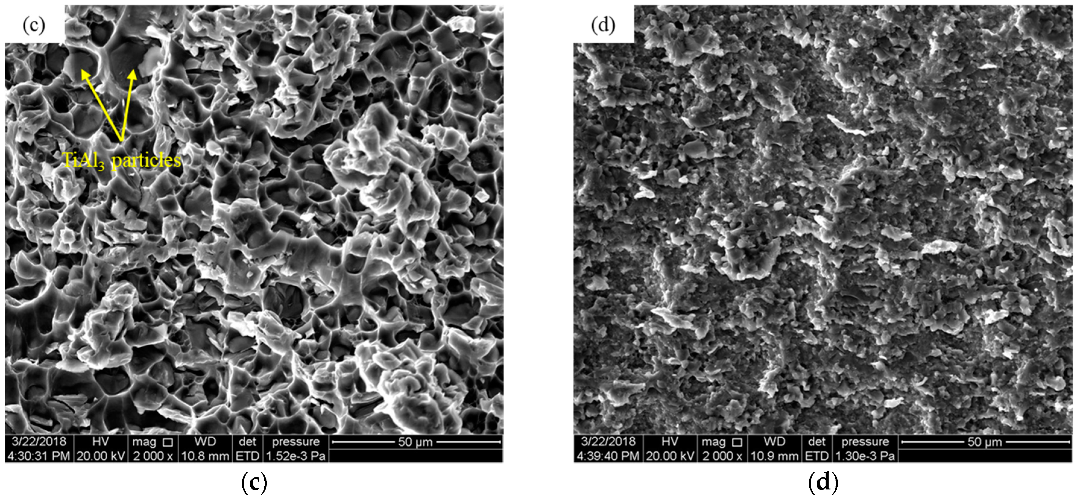
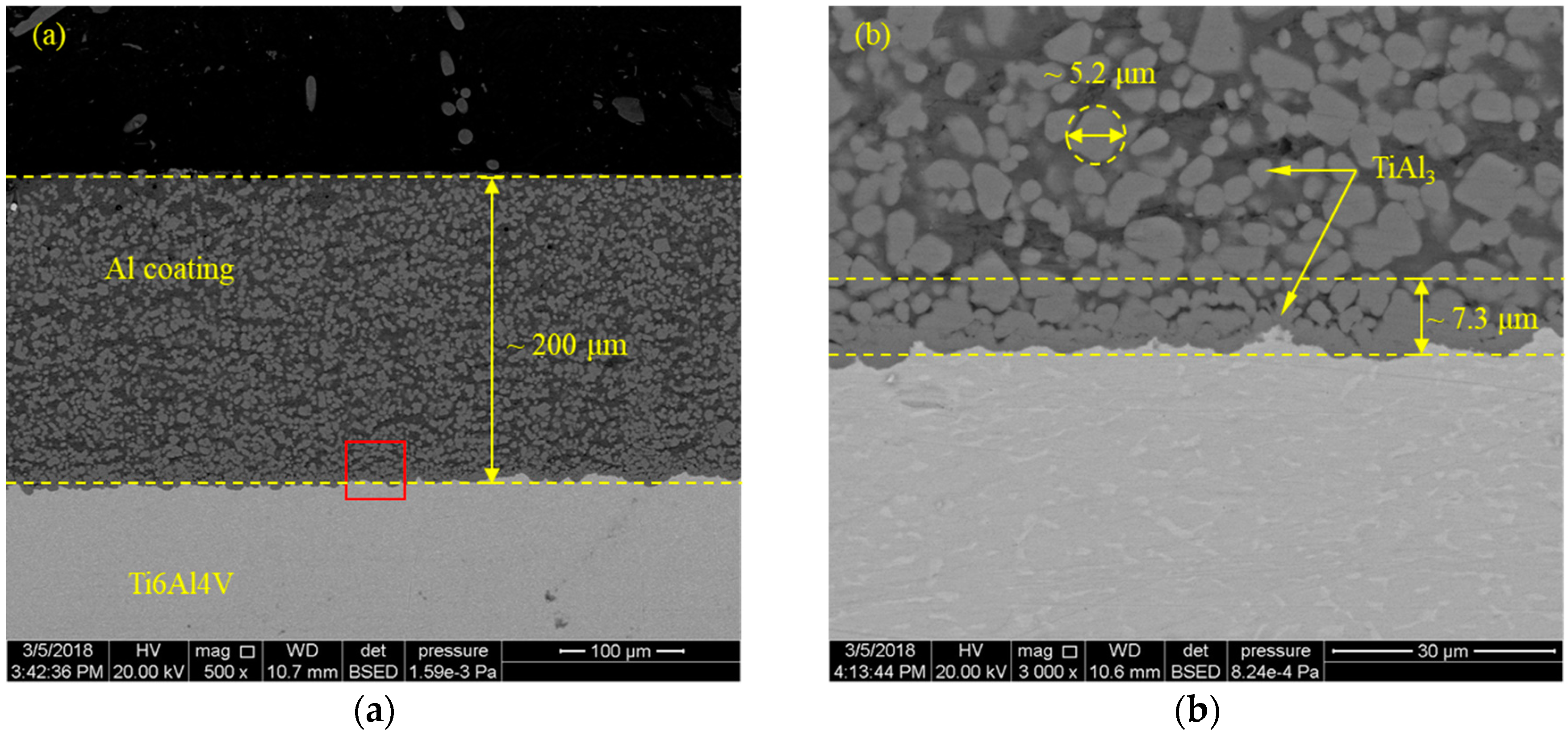
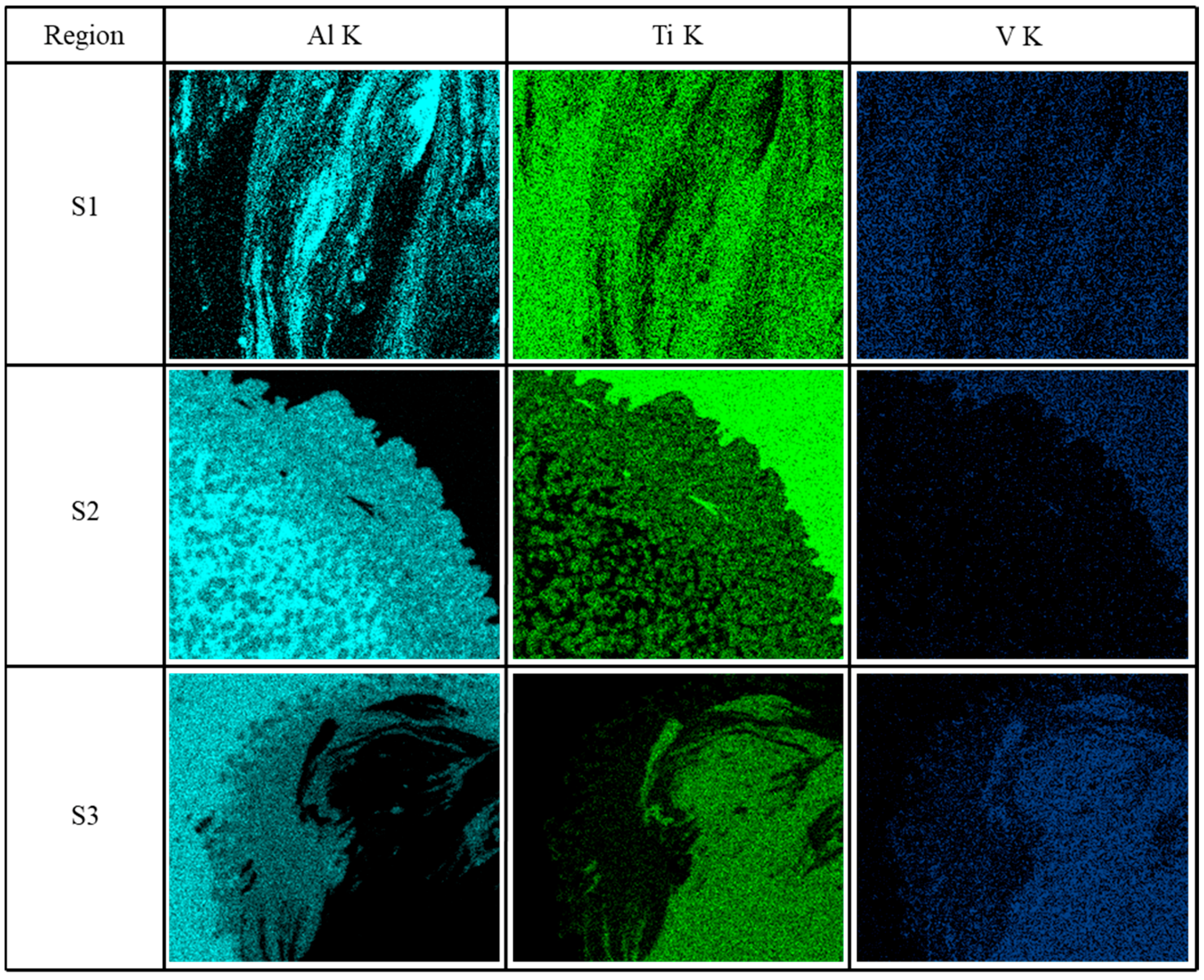
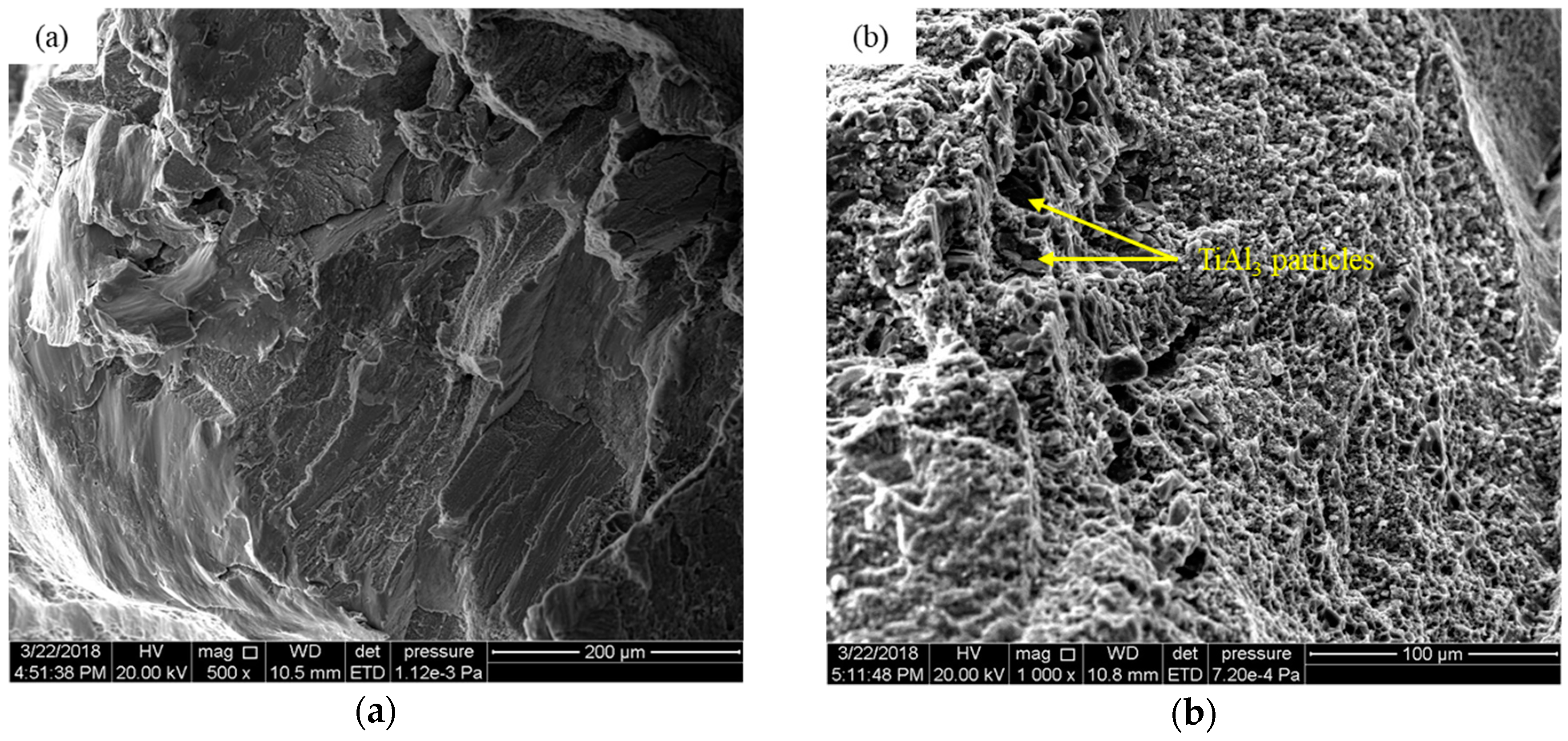
- The Zn interlayer and Al coating have no significant influence in the stir zone of the FSSW-B joint. Because of the extrusion force during the joining process, the introduced TiAl3 particles from Al coating are squeezed into the brazing zone, while the formed Zn–Al eutectic is squeezed out of the brazing zone.
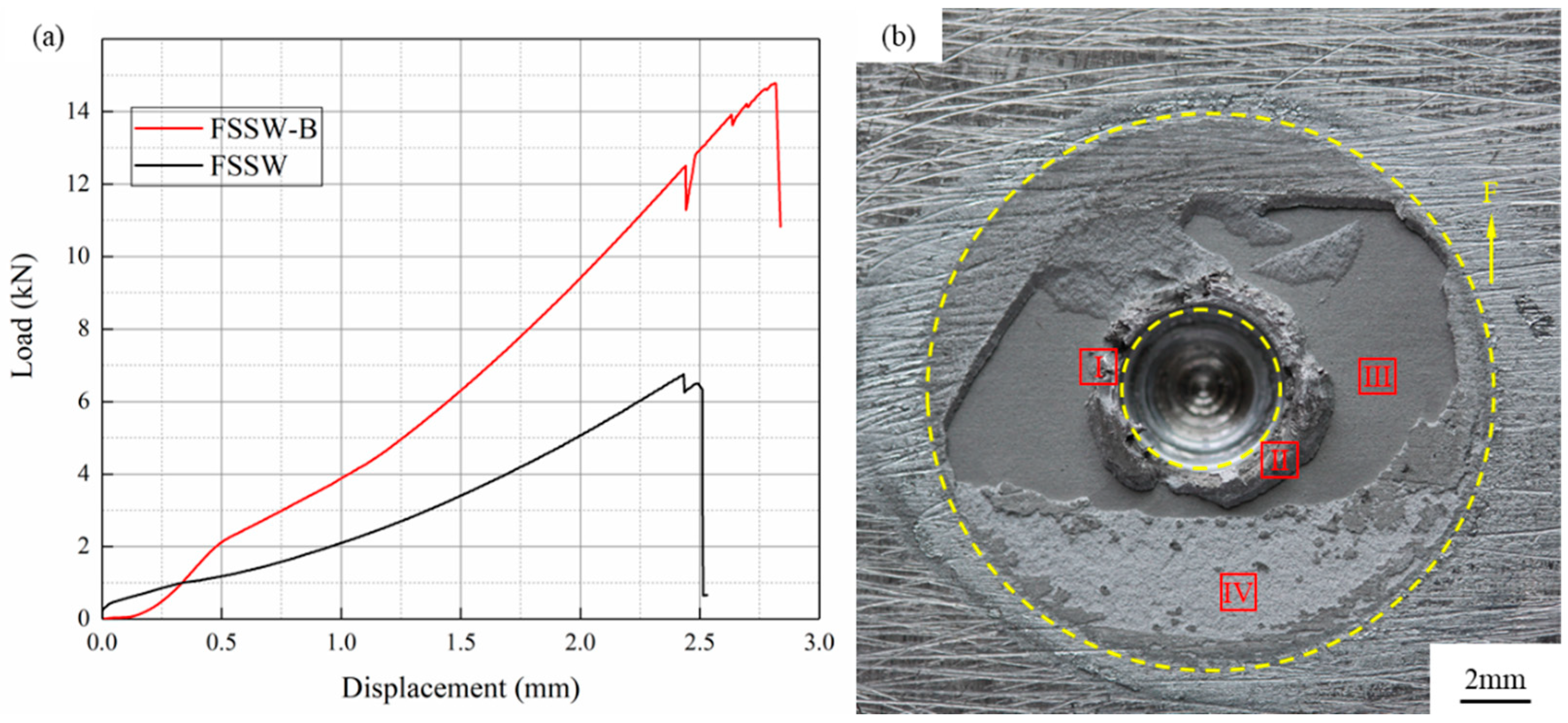
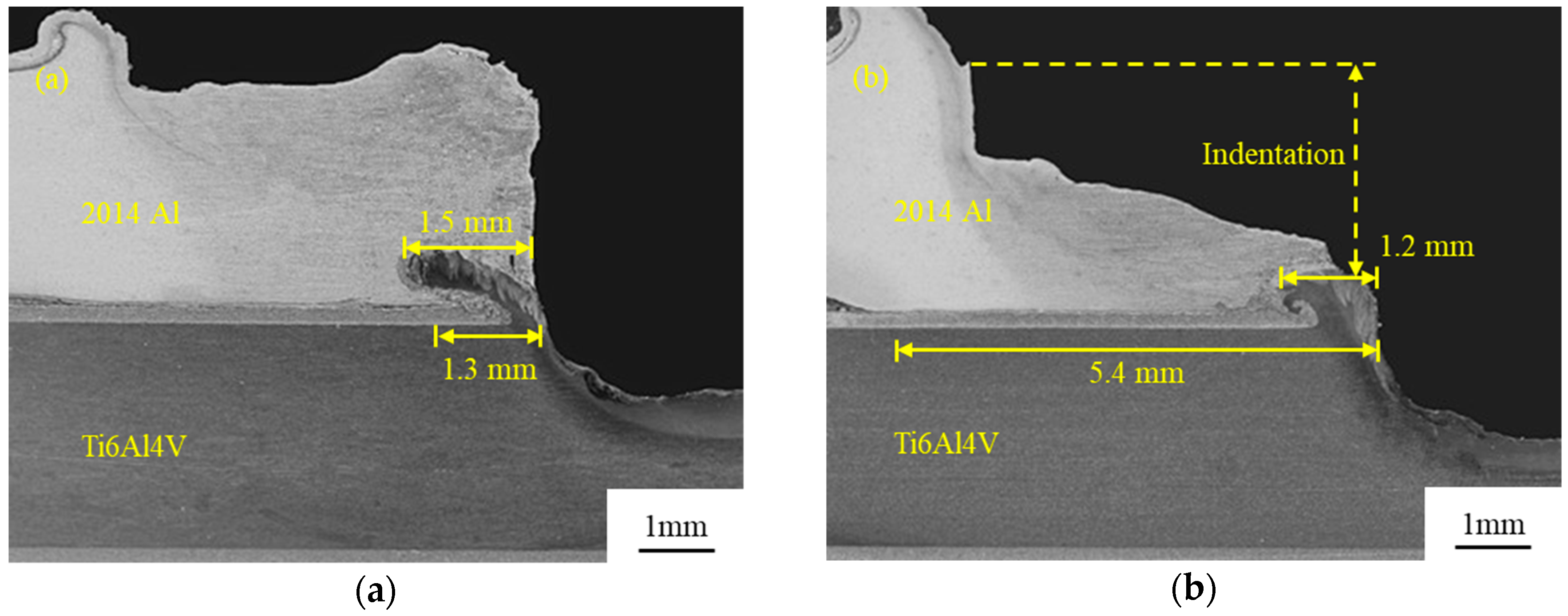
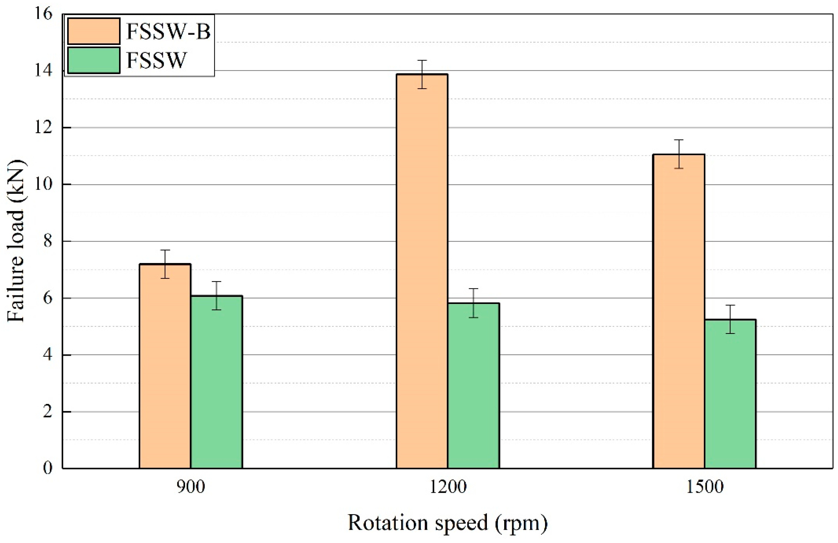
- The formation of the brazing zone significantly increases the joining area, causing the highest fracture load of the FSSW-B joint to be improved by 110% compared with that of the traditional FSSW joint.
- Fracture load of the joint was first increased and then decreased with increasing of the rotational speed, which was rationalized to the varied effective joining areas.
Author Contributions
Funding
Conflicts of Interest
References
- Micari, F.; Buffa, G.; Pellegrino, S.; Fratini, L. Friction Stir Welding as an Effective Alternative Technique for Light Structural Alloys Mixed Joints. Proced. Eng. 2014, 81, 74–83. [Google Scholar] [CrossRef]
- Mohammadi, J.; Behnamian, Y.; Mostafaei, A.; Izadi, H.; Saeid, T.; Kokabi, A.H.; Gerlich, A.P. Friction stir welding joint of dissimilar materials between AZ31B magnesium and 6061 aluminum alloys: Microstructure studies and mechanical characterizations. Mater. Charact. 2015, 101, 189–207. [Google Scholar] [CrossRef]
- Mallick, P.K. Materials, Design and Manufacturing for Lightweight Vehicles; Woodhead Publishing Limited: New Delhi, India, 2010; pp. 275–330. ISBN 978-1-84569-463-0. [Google Scholar]
- Vacchi, G.S.; Plaine, A.H.; Silva, R.; Sordi, V.L.; Suhuddin, U.F.H.; Alcântara, N.G.; Kuri, S.E.; Rovere, C.A.D. Effect of friction spot welding (FSpW) on the surface corrosion behavior of overlapping AA6181-T4/Ti-6Al-4V joints. Mater. Des. 2017, 131, 127–134. [Google Scholar] [CrossRef]
- ÇApar, N.; Kumru, U.; BaŞEr, T.A.; TekİN, G.; Saray, O. Friction Stir Spot Welding for Automotive Applications. Int. J. Adv. Auto. Technol. 2017, 1, 114–118. [Google Scholar] [CrossRef]
- Mironov, S.; Sato, Y.S.; Kokawa, H. Friction-stir welding and processing of Ti-6Al-4V Titanium alloy: A review. J. Mater. Sci. Technol. 2018, 34, 58–72. [Google Scholar] [CrossRef]
- Plaine, A.H.; Suhuddin, U.F.H.; Afonso, C.R.M.; Alcântara, N.G.; dos Santos, J.F. Interface formation and properties of friction spot welded joints of AA5754 and Ti6Al4V alloys. Mater. Des. 2016, 93, 224–231. [Google Scholar] [CrossRef]
- Sun, Q.J.; Li, J.Z.; Liu, Y.B.; Li, B.P.; Xu, P.W.; Feng, J.C. Microstructural characterization and mechanical properties of Al/Ti joint welded by CMT method—Assisted hybrid magnetic field. Mater. Des. 2017, 116, 316–324. [Google Scholar] [CrossRef]
- Chen, Y.C.; Nakata, K. Microstructural characterization and mechanical properties in friction stir welding of aluminum and titanium dissimilar alloys. Mater. Des. 2009, 30, 469–474. [Google Scholar] [CrossRef]
- Baqer, Y.M.; Ramesh, S.; Yusof, F.; Manladan, S.M. Challenges and advances in laser welding of dissimilar light alloys: Al/Mg, Al/Ti, and Mg/Ti alloys. Int. J. Adv. Manuf. Technol. 2018, 1–17. [Google Scholar] [CrossRef]
- Mishra, R.S.; Ma, Z.Y. Friction stir welding and processing. Mater. Sci. Eng. R: Rep. 2005, 50, 1–78. [Google Scholar] [CrossRef]
- Ren, J.; Li, Y.; Tao, F. Microstructure characteristics in the interface zone of Ti/Al diffusion bonding. Mater. Lett. 2002, 56, 647–652. [Google Scholar]
- Li, Y.J.; Gerasimov, S.A.; Wang, J.; Ma, H.J.; Ren, J.W. A study of vacuum diffusion bonding and interface structure of Ti/Al dissimilar materials. Mater. Sci. Technol. 2007, 15, 206–210. [Google Scholar]
- Chen, S.; Li, L.; Chen, Y.; Huang, J. Joining mechanism of Ti/Al dissimilar alloys during laser welding-brazing process. J. Alloy Compd. 2011, 509, 891–898. [Google Scholar] [CrossRef]
- Leo, P.; D’Ostuni, S.; Casalino, G. Low temperature heat treatments of AA5754-Ti6Al4V dissimilar laser welds: Microstructure evolution and mechanical properties. Opt. Laser Technol. 2018, 100, 109–118. [Google Scholar] [CrossRef]
- Lv, S.; Cui, Q.; Huang, Y.; Jing, X. Influence of Zr addition on TIG welding–brazing of Ti–6Al–4V toAl5A06. Mater. Sci. Eng. A 2013, 568, 150–154. [Google Scholar] [CrossRef]
- Mehta, K.P.; Badheka, V.J. A Review on Dissimilar Friction Stir Welding of Copper to Aluminum: Process, Properties, and Variants. Mater. Manuf. Process. 2015, 31, 233–254. [Google Scholar] [CrossRef]
- Yang, X.W.; Fu, T.; Li, W.Y. Friction Stir Spot Welding: A Review on Joint Macro- and Microstructure, Property, and Process Modelling. Adv. Mater. Sci. Eng. 2014, 2014, 1–11. [Google Scholar] [CrossRef]
- Padhy, G.K.; Wu, C.S.; Gao, S. Friction stir based welding and processing technologies—processes, parameters, microstructures and applications: A review. J. Mater. Sci. Tech. 2018, 34, 1–38. [Google Scholar] [CrossRef]
- Kim, D.; Badarinarayan, H.; Ryu, I.; Kim, J.H.; Kim, C.; Okamoto, K.; Wagoner, R.H.; Chung, K. Numerical simulation of friction stir spot welding process for aluminum alloys. Metals Mater. Int. 2010, 16, 323–332. [Google Scholar] [CrossRef]
- Kim, J.-R.; Ahn, E.-Y.; Das, H.; Jeong, Y.-H.; Hong, S.-T.; Miles, M.; Lee, K.-J. Effect of tool geometry and process parameters on mechanical properties of friction stir spot welded dissimilar aluminum alloys. Int. J. Precis. Eng. Manuf. 2017, 18, 445–452. [Google Scholar] [CrossRef]
- Zhang, G.; Zhang, L.; Kang, C.; Zhang, J. Development of friction stir spot brazing (FSSB). Mater. Des. 2016, 94, 502–514. [Google Scholar] [CrossRef]
- Zhou, L.; Luo, L.Y.; Zhang, T.P.; He, W.X.; Huang, Y.X.; Feng, J.C. Effect of rotation speed on microstructure and mechanical properties of refill friction stir spot welded 6061-T6 aluminum alloy. Int. J. Adv. Manuf. Technol. 2017, 92, 3425–3433. [Google Scholar] [CrossRef]
- Sun, Y.F.; Fujii, H.; Takaki, N.; Okitsu, Y. Microstructure and mechanical properties of dissimilar Al alloy/steel joints prepared by a flat spot friction stir welding technique. Mater. Des. 2013, 47, 350–357. [Google Scholar] [CrossRef]
- Swamy, M.M.; Muthukumaran, S.; Kiran, K. A Study on Friction Stir Multi Spot Welding Techniques to Join Commercial Pure Aluminum and Mild Steel Sheets. Trans. Indian Inst. Metals 2016, 70, 1221–1232. [Google Scholar] [CrossRef]
- Yu, W.; Shao, J.; Chen, D.; Liu, S. Effect of transitional layer on property and microstructure of FSB joints of aluminum and steel. Trans. China Weld. 2015, 36, 85–89. [Google Scholar]
- Huang, G.; Feng, X.; Shen, Y.; Zheng, Q.; Zhao, P. Friction stir brazing of 6061 aluminum alloy and H62 brass: Evaluation of microstructure, mechanical and fracture behavior. Mater. Des. 2016, 99, 403–411. [Google Scholar] [CrossRef]
- Gan, R.; Jin, Y. Friction stir-induced brazing of Al/Mg lap joints with and without Zn interlayer. Sci. Technol. Weld. Join. 2017, 23, 164–171. [Google Scholar] [CrossRef]
- Zhang, G.-F.; Zhang, K.; Guo, Y.; Zhang, J.-X. A Comparative Study of Friction Stir Brazing and Furnace Brazing of Dissimilar Metal Al and Cu Plates. Metall. Microstuct. Anal. 2014, 3, 272–280. [Google Scholar] [CrossRef]
- Xu, R.Z.; Ni, D.R.; Yang, Q.; Liu, C.Z.; Ma, Z.Y. Influence of Zn coating on friction stir spot welded Magnesium-Aluminium joint. Sci. Technol. Weld. Join. 2016, 22, 512–519. [Google Scholar] [CrossRef]
- Boucherit, A.; Avettand-Fènoël, M.N.; Taillard, R. Effect of a Zn interlayer on dissimilar FSSW of Al and Cu. Mater. Des. 2017, 124, 87–99. [Google Scholar] [CrossRef]
- Zhou, W.B.; Teng, G.B.; Liu, C.Y.; Qi, H.Q.; Huang, H.F.; Chen, Y.; Jiang, H.J. Microstructures and Mechanical Properties of Binary Al-Zn Alloys Fabricated by Casting and Heat Treatment. J. Mater. Eng. Perform. 2017, 26, 3977–3982. [Google Scholar] [CrossRef]
- Zhang, Z.G.; Peng, Y.P.; Mao, Y.L.; Pang, C.J.; Lu, L.Y. Effect of hot-dip aluminizing on the oxidation resistance of Ti–6Al–4V alloy at high temperatures. Corros. Sci. 2012, 55, 187–193. [Google Scholar] [CrossRef]
- Ebrahimian, A.; Kokabi, A.H. Friction stir soldering: A novel route to produce graphite-copper dissimilar joints. Mater. Des. 2017, 116, 599–608. [Google Scholar] [CrossRef]
- Sadeq, F.O.; Sharifitabar, M.; Afarani, M.S. Synthesis of Ti–Si–Al coatings on the surface of Ti–6Al–4V alloy via hot dip siliconizing route. Surf. Coat. Technol. 2018, 337, 349–356. [Google Scholar] [CrossRef]
- Zhang, Z.G.; Teng, X.; Xiang, H.F.; Sheng, Y.G.; Zhang, X.J. Preparation of TiAl3 Coating on γ-TiAl through Hot-dip Aluminizing and Subsequent Interdiffusion Treatment: High Temperature Materials and Processes. High Temp. Mater. Process. 2009, 28, 115–119. [Google Scholar] [CrossRef]
- Badarinarayan, H.; Shi, Y.; Li, X.; Okamoto, K. Effect of tool geometry on hook formation and static strength of friction stir spot welded aluminum 5754-O. sheets. Int. J. Mach. Tool. Manuf. 2009, 49, 814–823. [Google Scholar] [CrossRef]
- Yin, Y.H.; Sun, N.; North, T.H.; Hu, S.S. Hook formation and mechanical properties in AZ31 friction stir spot welds. J. Mater. Process. Technol. 2010, 210, 2062–2070. [Google Scholar] [CrossRef]
- Rao, H.M.; Yuan, W.; Badarinarayan, H. Effect of process parameters on mechanical properties of friction stir spot welded Magnesium to aluminum alloys. Mater. Des. 2015, 66, 235–245. [Google Scholar] [CrossRef]
- Zhou, X.; Huang, Y.; Chen, Y.; Peng, P. Laser joining of Mo and Ta sheets with Ti6Al4V or Ni filler. Opt. Laser Technol. 2018, 106, 487–494. [Google Scholar] [CrossRef]
- Zhou, X.; Chen, Y.; Huang, Y.; Mao, Y.; Yu, Y. Effects of niobium addition on the microstructure and mechanical properties of laser-welded joints of NiTiNb and Ti6Al4V alloys. J. Alloy. Compd. 2018, 735, 2616–2624. [Google Scholar] [CrossRef]
- Pouquet, J.; Miranda, R.M.; Williams, S. Dissimilar laser welding of NiTi to stainless steel. Int. J. Adv. Manuf. Technol. 2012, 61, 205–212. [Google Scholar] [CrossRef]
- Huang, Y.; Lv, Z.; Wan, L.; Shen, J.; dos Santos, J.F. A new method of hybrid friction stir welding assisted by friction surfacing for joining dissimilar Ti/Al alloy. Mater. Lett. 2017, 207, 172–175. [Google Scholar] [CrossRef]
- Song, Z.; Nakata, K.; Wu, A.; Liao, J.; Zhou, L. Influence of probe offset distance on interfacial microstructure and mechanical properties of friction stir butt welded joint of Ti6Al4V and A6061 dissimilar alloys. Mater. Des. 2014, 57, 269–278. [Google Scholar] [CrossRef]
- Su, P.; Gerlich, A.; North, T.H.; Bendzsak, G.J. Intermixing in Dissimilar Friction Stir Spot Welds. Metall. Mater. Trans. A 2007, 38, 584–595. [Google Scholar] [CrossRef]
- Gale, W.F.; Butts, D.A. Transient liquid phase bonding. Sci. Technol. Weld. Join. 2013, 9, 283–300. [Google Scholar] [CrossRef]
- Zhang, G.F.; Zhang, K.; Zhang, L.J.; Zhang, J.X. Approach to disrupting thick intermetallic compound interfacial layer in friction stir brazing (FSB) of Al/Cu plates. Sci. Technol. Weld. Join. 2014, 19, 554–559. [Google Scholar] [CrossRef]
- Zhang, G.F.; Su, W.; Zhang, J.; Zhang, J.X. Visual observation of effect of tilting tool on forging action during FSW of aluminium sheet. Sci. Technol. Weld. Join. 2013, 16, 87–91. [Google Scholar] [CrossRef]
- Su, P.; Gerlich, A.; North, T.H.; Bendzsak, G.J. Energy Generation and Stir Zone Dimensions in Friction Stir Spot Welds; SAE Technical Paper Series; SAE International: Warrendale, PA, USA, 2006. [Google Scholar]
- Li, S.; Chen, Y.; Zhou, X.; Kang, J.; Huang, Y.; Deng, H. High-strength titanium alloy/steel butt joint produced via friction stir welding. Mater. Lett. 2019, 234, 155–158. [Google Scholar] [CrossRef]
- Kuang, B.; Shen, Y.; Chen, W.; Yao, X.; Xu, H.; Gao, J.; Zhang, J. The dissimilar friction stir lap welding of 1A99 Al to pure Cu using Zn as filler metal with “pinless” tool configuration. Mater. Des. 2015, 68, 54–62. [Google Scholar] [CrossRef]
- Yin, Y.H.; Sun, N.; North, T.H.; Hu, S.S. Influence of tool design on mechanical properties of AZ31 friction stir spot welds. Sci. Technol. Weld. Join. 2010, 15, 81–86. [Google Scholar] [CrossRef]
- Gerlich, A.; Su, P.; North, T.H. Tool penetration during friction stir spot welding of Al and Mg alloys. J. Mater. Sci. 2005, 40, 6473–6481. [Google Scholar] [CrossRef]
- Choi, D.H.; Lee, C.Y.; Ahn, B.W.; Choi, J.H.; Yeon, Y.M.; Song, K.; Park, H.S.; Kim, Y.J.; Yoo, C.D.; Jung, S.B. Frictional wear evaluation of WC–Co alloy tool in friction stir spot welding of low carbon steel plates. Int. J. Refract. Metals Hard Mater. 2009, 27, 931–936. [Google Scholar] [CrossRef]


| Alloys | Cu | Si | Mn | Mg | Fe | Zn | Ti | Ni | Al | V | C | N | H | O |
|---|---|---|---|---|---|---|---|---|---|---|---|---|---|---|
| 2014-T4 | 4.3 | 1.0 | 0.73 | 0.55 | 0.3 | 0.08 | 0.02 | 0.02 | Bal. | - | - | - | - | - |
| Ti6Al4V | - | - | - | - | 0.026 | - | Bal. | - | 6.0 | 4.0 | 0.015 | 0.008 | 0.007 | 0.06 |
© 2018 by the authors. Licensee MDPI, Basel, Switzerland. This article is an open access article distributed under the terms and conditions of the Creative Commons Attribution (CC BY) license (http://creativecommons.org/licenses/by/4.0/).
Share and Cite
Zhou, X.; Chen, Y.; Li, S.; Huang, Y.; Hao, K.; Peng, P. Friction Stir Spot Welding-Brazing of Al and Hot-Dip Aluminized Ti Alloy with Zn Interlayer. Metals 2018, 8, 922. https://doi.org/10.3390/met8110922
Zhou X, Chen Y, Li S, Huang Y, Hao K, Peng P. Friction Stir Spot Welding-Brazing of Al and Hot-Dip Aluminized Ti Alloy with Zn Interlayer. Metals. 2018; 8(11):922. https://doi.org/10.3390/met8110922
Chicago/Turabian StyleZhou, Xingwen, Yuhua Chen, Shuhan Li, Yongde Huang, Kun Hao, and Peng Peng. 2018. "Friction Stir Spot Welding-Brazing of Al and Hot-Dip Aluminized Ti Alloy with Zn Interlayer" Metals 8, no. 11: 922. https://doi.org/10.3390/met8110922
APA StyleZhou, X., Chen, Y., Li, S., Huang, Y., Hao, K., & Peng, P. (2018). Friction Stir Spot Welding-Brazing of Al and Hot-Dip Aluminized Ti Alloy with Zn Interlayer. Metals, 8(11), 922. https://doi.org/10.3390/met8110922