Article

Manufacturing of High-Performance Bi-Metal Bevel Gears by Combined Deposition Welding and Forging

1
Institute of Forming Technology and Machines, Leibniz Universität Hannover, 30823 Garbsen, Germany
2
Institute of Material Science, Leibniz Universität Hannover, 30823 Garbsen, Germany
3
Laser Zentrum Hannover e.V., 30419 Hannover, Germany
*
Author to whom correspondence should be addressed.
Metals 2018, 8(11), 898; https://doi.org/10.3390/met8110898
Submission received: 27 September 2018 / Revised: 25 October 2018 / Accepted: 26 October 2018 / Published: 2 November 2018

Abstract

:
The present paper describes a new method concerning the production of hybrid bevel gears using the Tailored Forming technology. The main idea of the Tailored Forming involves the creation of bi-metal workpieces using a joining process prior to the forming step and targeted treatment of the resulting joint by thermo-mechanical processing during the subsequent forming at elevated temperatures. This improves the mechanical and geometrical properties of the joining zone. The aim is to produce components with a hybrid material system, where the high-quality and expensive material is located in highly stressed areas only. When used appropriately, it is possible to reduce costs by using fewer high-performance materials than in a component made of a single material. There is also the opportunity to significantly increase performance by combining special load-tailored high-performance materials. The core of the technology consists in the material-locking coating of semi-finished parts by means of plasma-transferred-arc welding (PTA) and subsequent forming. In the presented investigations, steel cylinders made of C22.8 are first coated with the higher-quality heat-treatable steel 41Cr4 using PTA-welding and then hot-formed in a forging process. It could be shown that the applied coating can be formed successfully by hot forging processes without suffering any damage or defects and that the previous weld structure is completely transformed into a homogeneous forming-typical structure. Thus, negative thermal influences of the welding process on the microstructure are completely neutralized.

1. Introduction

Following the current trend towards engine downsizing and increasing output, technical components with improved performance and less weight are required. In this context, conventional materials commonly used in the established production processes approach their material-specific limits. In contrast, producing components from a combination of multiple materials could extend functionality and properties adjusted to specific applications and load conditions. Thus, the development of efficient process routes for the production of multi-material components has been gaining in importance in recent years. With this objective, the Collaborative Research Centre 1153 (CRC 1153) “Tailored Forming” investigates a novel process chain, which includes the joining of raw materials to a bi-metal workpiece in the first step, followed by the forming to the final geometry in a second step. Thus, the focus of the Tailored Forming technology is set on the targeted treatment of already existing joint by means of thermo-mechanical processing during forming. Using this concept, it is possible to improve microstructure, mechanical properties and the bonding quality in the joining zone. The current study is focused on the manufacturing of bi-metal bevel gears made of two different steels whereby material joining is performed by a deposition welding process. Subsequently, the semi-finished bi-metal workpieces are formed by die-forging. This investigation presents the analysis of the resulting microstructure and shape evaluation of the joining zone after the welding and forging process. The novelty of this work is that solid semi-finished products consisting of two materials, which are produced by plasma-transferred arc welding of steel, are undergoing a thermo-mechanical treatment within the subsequent forming step. Thus, high-performance hybrid components can be produced. The aim is to show that the previously existing weld structure can be transformed into a forming structure by the forming process, and therefore negative effects of the heat influence from the welding in the finished component are negligible.

2. Survey of the Current Literature

Deposition welding represents an efficient method for manufacturing hybrid material parts. This technique allows for a local improvement of material properties by applying high-performance metallic coating materials to the substrate material. Depending on the energy source used for material melting, various types of deposition welding processes can be distinguished. Each process has advantages for certain applications. Methods that are well established in the industry nowadays to apply selective metal layers include metal inert gas welding, submerged arc deposition, plasma-transferred arc (PTA), laser deposition welding or electro-slag-welding [1].
Plasma-transferred arc deposition welding is considered the most suitable process for this purpose because of its wide range of flexibility with regard to the alloys that can be processed, and it enables high deposition rates. The process is strongly recommended for applying high-performance coatings, as the majority of hard and wear resistant coating materials are only available in powder form. This is especially the case for heat-treatable steels. These steels usually have high carbon equivalents (CEV > 0.5) and are declared as difficult to weld or non-weldable according to current data sheets. Due to this fact, the welding process can be very challenging [2].
Plasma powder deposition welding uses a plasma arc as a heat source and metal powder as filler material. The energy input of the process can be precisely controlled, and enables high application rates. The welding process is similar to tungsten inert gas (TIG) welding, in which the arc burns between non-melting tungsten electrodes. Argon is used as shield gas. Compared to other processes, the geometric accuracy of PTA-welding is relatively imprecise. However, Jhavar et al. explain the development of a μ-PTA process for the cost-efficient and energy-efficient repair of small dies and moulds [3]. Ulutan et al. investigated the effects of PTA on the microstructure and hardness of AISI 5115 steel coated with FeCrC-powder [4]. Motallebzadeh et al. implemented welding of a hypo-eutectic CoCrWC hard facing alloy onto a steel substrate by PTA deposition welding and investigated the microstructure and high-temperature tribological performance [5]. Ferozhkhan et al. performed welding of Stellite 6 alloys on stainless steel for wear resistance investigations [6]. Xinke Denk et al. welded a wear-resistant Fe-Mo alloy coating on an AISI 1045 steel substrate by plasma transferred arc (PTA) cladding, using pure Mo powders as the precursor material [7]. PTA-welding can also be used for in-situ alloying directly in the welding process. Youlu Yuan et al. successfully synthesized In-situ WC/Fe carbide coatings by PTA-welding and studied the wear properties [8]. The welding process can also be used for additive manufacturing. For example, Cheng Liu et al. analyzed the geometric stability and microstructure characteristics of metal additive manufactured parts using plasma transferred arc with WCp/NiBSi metal matrix composites. A macrohardness of HRC 65 ± 1 could be achieved [9].
Bulk metal forming offers high potential for the production of near-net-shape multi-material components with complex geometries, optimised grain flow and outstanding mechanical properties. In previous studies, the manufacturing of multi-material compounds is commonly performed by processes combining forming and joining in a single stage. For example, Wohletz and Groche examined the joining of steel and aluminium raw parts (C15/AW 6082 T6) by means of combined forward and cup extrusion [10]. The study of Kong et al. focused on joining by means of forge welding of stainless steel (AISI 316L) and aluminium (6063) [11]. It was established that among the other process parameters, the forming temperature has the most decisive influence on the resulting quality and the tensile strength of the joint. The use of inhomogeneous temperature distribution between steel and aluminium raw parts for compound forging was investigated by Behrens et al. in order to achieve an approximately equal forming behaviour of both materials [12]. The achieved results were transferred to the forging of hybrid steel/aluminium gears (S235JR/EN AW 6082). Essa et al. studied the cold upsetting process of bi-metal billets consisting of a steel/steel combination (C15E/C45E) [13]. However, a steel/steel combination, especially in the case of a high-strength steel, can offer only a limited or moderate formability at room temperature. Joining by plastic deformation at high temperatures is challenging in terms of possible oxide scale formation in the joining zone with its negative impact on the final bond strength, or in terms of cost-efficiency in the case of utilizing a shielding gas atmosphere to prevent the oxidation. Thus, hot forming of previously welded blanks represents an interesting approach for steel/steel parts processing. Hereby, the main issues involve a sufficient deformation of the welded component, in order to refine the coarse welding microstructure as well as an appropriate forming process design to ensure the right position and thickness of the high-strength steel alloy after intensive material flow.
In contrast to the joining by forming, few research works address the issue of the bulk metal forming of pre-joined multi-material workpieces. Klotz at al. deal with the isothermal forging of bi-metal gas turbine discs made of two different Ni-based superalloys from hot isostatically pressed billets [14]. Pfeiffer et al. implemented the co-extrusion of non-centric steel-reinforced aluminium profiles with subsequent forging [15]. Förster et al. carried out numerical and experimental investigations on a process chain consisting of hydrostatic co-extrusion of Al-Mg rods with aluminium on the external diameter and subsequent forging [16]. Domblesky et al. investigated hot compression tests in order to study the forgeability of friction-welded bi-metal pre-forms combining copper, aluminium and steel [17]. Frischkorn et al. examined the hot forging behaviour of further material combinations comprising steel, aluminium, titanium and Inconel [18]. Wang et al. conducted numerical and experimental investigations on the hot upsetting of bi-metal billets produced by weld cladding (C15/316L) [19].

3. Materials and Methods

3.1. Bevel Gears and Semi-Finished Workpieces

An application example is a bevel gear, where the different component regions are exposed to varying load conditions. Due to high loads on the contact area between two bevel gears, the tooth flanks are exposed to higher stresses than the rest of the component. Accordingly, high performance properties should be employed on the pitch surface and are not required in the centre. Therefore, a multi-material approach could be well appropriate for this application. In the considered bevel gear, a high-performance material is placed only in the critically loaded areas to counteract the high tribological stresses (e.g., high tensile steel 41Cr4). For the inner section, low-performance materials with a high toughness, ductility and breaking resistance are used (e.g., low-alloyed steel C22.8). The investigated bimetallic bevel gear is schematically illustrated in Figure 1b. The corresponding semi-finished workpieces were designed in accordance with the load collective of the final parts (Figure 1a). For the production of hybrid workpieces, a cylindrical base material was coated with a metallic layer by means of deposition welding. The thickness of the examined layer was chosen exemplarily with regard to the previous research on the manufacturing of cylindrical gear wheels by compound forging [20]. The crucial criterion was to ensure a full cover of high-stressed areas of the final bevel gear. Thus, the thickness of the welded layer includes also allowance required for the secondary processes (e.g., machining). Within a subsequent hot forging process, the deposition-welded workpieces with coaxial material arrangement were formed to hybrid bevel gears. The main dimensions of the bi-metal workpieces and bevel gears are listed in Table 1. The workpieces were turned after the welding process in order to achieve the required workpiece volume. The outside diameter of the bevel gear corresponds with the diameter of the crown circle.

3.2. Deposition Welding

All deposition processes using welding commonly struggle with the problem of heat-affected zones, which are created near the welding seams due to the high temperatures of the liquid weld metal. The welding heat acts as a short heat treatment on the component and has a negative influence on the microstructure of the material. As an example, this can result in increased brittleness and hardness so that mechanical processing becomes more difficult. However, if a welding process is followed by a hot forging process with a sufficient degree of forming and compressive stress states, most decisive defects caused by the previous welding process (e.g., pores, cracks and coarse microstructure) can be eliminated. Within the studied gear component, a highly effective plastic strain of approx. 2 within the welded casing and prevailing compressive stress states, which a typically for closed die hot forging processes [21], contribute to an intensive dynamic recrystallization and pore healing of the coarse welding microstructure. The positive influence of forming has already been demonstrated in previous studies on hybrid blanks in cross wedge rolling [22,23].
In the current study, the manufacturing of bi-metal semi-finished workpieces has been performed by PTA deposition welding. The welding tests were conducted with an automated welding system consisting of a six-axis industrial robot Reis RV-16 (Reis Group Holding GmbH & Co KG, Obernburg am Main, Germany), the PTA Torch Kennametal Stellite HPM 302 and the power supply Stellite Starweld PTA 302 Control (Kennametal Inc., Belleville, ON, Canada) (Figure 2a). The PTA welding process and its parameters are represented in Figure 2b and in Table 2, respectively. During the process, 41Cr4 powder is deposited on a cylindrical substrate made of C22.8. Due to the melting of the coating layer accompanied by high temperature input, the substrate material heats up strongly and the penetration of the filler material increases. In order to decrease this effect, the welding current is reduced evenly from 150 ampere at the start, to 110 ampere until the end of the process is reached. During welding under the PTA torch, the cylindrical specimen rotates 15 times in total. Due to the rotational movement of the workpiece and the axial movement of the torch, the separate welding seams are deposited in a helical form which results in a wavy pattern of coating surface and interface zone between the applied materials.
In order to weld 41Cr4 without pores and cracks, the welding process was adjusted to a suitable parameter set. With the steel 41Cr4, there is a risk of cracking, especially if the material cools down too quickly. Therefore, a slow welding speed of 1.7 mm/s was selected. This leads to a strong heating of the base material, which prevents a self-quenching of the cladding material, especially at the beginning of the cladding process. Due to the pendulum movement with a frequency of 2 Hz carried out by the welding torch, a wide weld seam with a large material volume is welded on, which stores more heat than a seam produced without a pendulum movement. Due to the pendulum movement and the slow welding speed, the molten pool solidifies very late and is thoroughly mixed. This leads to a very good degassing of the melt and prevents the inclusion of pores. If the plasma gas is set too high, it can penetrate the melt like a needle and gas-filled pores can remain during solidification. Therefore, the plasma gas flow has been additionally reduced to the technical limit of 1.5 L/h. With a further reduction, the burner clogged due to too low gas velocities. This plasma gas velocity therefore represents the stable process limit for the current equipment.

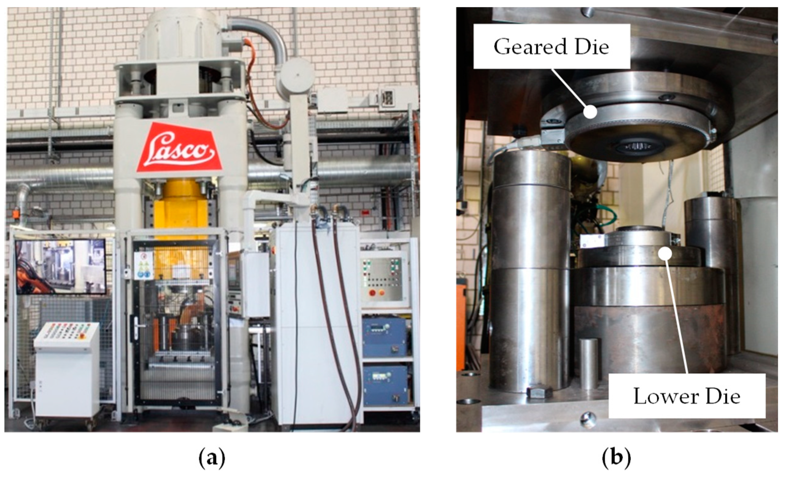
3.3. Forming of Bi-Metal Bevel Gears

For the manufacturing of hybrid bevel gears, the forging tool system depicted in Figure 3b has been developed [24]. It allows a forming of bi-metal semi-finished workpieces to the final geometry in a single stage. The corresponding tool system is constructed modularly and consists in general of a lower die and a pre-stressed geared die which is installed in the upper tool in order to ensure smooth removal of the forged gears. For the experimental forging tests, the forming tool system was integrated in the screw press Lasco SPR500 with a maximum capacity of 40 kJ (LASCO Umformtechnik GmbH, Coburg, Germany) (Figure 3a). The key parameters of the forging process are presented in Table 3.
Single bi-metal workpieces were heated up to the forming temperature of approx. 1200 °C by means of induction heating for about 50 s. The chosen temperature range is typical for the hot forging of steel and allows the achievement of high formability, appropriate mould filling and refinement of microstructure (e.g., by dynamic recrystallisation) in a single forming step [25]. In the case of examined bi-metal workpieces, only slight differences in the flow stresses and in forming behaviour of both steels (C22.8 and 41Cr4) are to be expected at the forming temperature. Therefore, a uniform temperature distribution within the workpieces was used for the forging process. The warm workpieces were transported to the forging dies pre-heated to 200 °C and subsequently formed to the final geometry. Figure 4 shows a bevel gear directly after the forging process. After the forming stage, the bevel gears were cooled in sand. The forged parts displayed complete mould filling without any outward forging defects (e.g., folds), even in the crucial geared area.

3.4. Characterization and Microstructural Analysis

For the analysis of the manufactured components, metallographic cuts were made and subsequently prepared and evaluated on the basis of photographs. For this purpose, the components were cut using a wet cut-off machine Secotom-10 (Struers GmbH, Willich, Germany) and embedded in transparent investment material. Subsequently, grinding was performed on cylindrical grinding machines Tegramin-30 (Struers GmbH, Willich, Germany) with grinding wheels of grain sizes H180 to H2500. After that, the samples were then polished in a polishing machine VibroMet 2 (Buehler GmbH, Esslingen Am Neckar, Germany). First, automatic hardness tests with Q10 A+ (Qness GmbH, Golling, Austria) were performed on polished samples. For metallographic examinations, the samples were additionally etched with two percent nitric acid. A Leica DM4000 M (Leica Camera AG, Wetzlar, Germany) was used as microscope.

4. Results and Discussion

For a characterisation of the microstructure evolution, the specimens extracted from deposition-welded and forged parts were metallographically investigated. The metallographic cuts with resulting macro- and microstructures are presented in Figure 5 and Figure 6. The micrographs show an appropriate material compound without any material separation, damage or microscopic cracks after deposition welding such as after forging. In the longitudinal section along the upsetting direction (shown with a red line), the wavy shape of the interface zone, resulting from the welding process, can be observed (Figure 5a). After the forming process, the wavy interface contour is maintained wavelike in a modified form (Figure 5b). Due to upsetting, the maximum thickness of the welded layer was increased by 76% and the width of the welding seams was reduced by approx. 30% in the middle of the tooth tip (Table 4). The resulting wavy contour of the bonding zone may lead to a higher total joining surface area between the materials and thus to a better bonding quality.
Due to higher plastic strains in the tooth root area, the welded layer at the tooth root is significantly thinner than at the tooth tip (Figure 6b, left). This can also be seen from the linear flow of elongated grains. Before forming, the welded layer shows a primarily pearlitic microstructure with a certain amount of ferrite concentrated at the grain boundaries. The core material (C22.8) exhibits so-called Widmannstaetten ferritic (WS-ferrite) patterns directly at the interface layer, induced by high cooling rates after the welding process (Figure 6a, right). The ferritic-pearlitic structure in the cylinder core is a common microstructure for the steel C22.8. After the subsequent forming, the resulting microstructure became finer and more homogeneous as a result of recrystallisation processes and plastic strains at hot forming temperatures (1200 °C). As shown in Figure 6b (middle, right), it completely consists of fine ferrite and pearlite grains.
In addition, the hardness profiles were examined from the sample edge in radial direction to the middle in both, deposition-welded workpieces and forged bevel gears (Figure 7). The measurement lines are respectively marked with white arrows in Figure 6. In the case of the bevel gear, the measuring line was located at the middle of the tooth tip. The hardness was measured in Vickers HV 0.1 with the WOLPERT TESTOR 930/250 (Instron Deutschland Gmbh, Aachen, Germany), hardness tester. The hardness values differed from the deposition-welded layer (41Cr4) to the core material (C22.8). A hardness drop of approx. 21% is observed in the coating layer after forging, while the hardness of the core material does not change significantly. This can be explained by structural transformation at hot forming temperatures (1200 °C) and slower cooling rates after the forging process compared with the welding process. After welding, the component cools down faster due to self-quenching, which leads to a higher hardness, especially in the outer area.
In comparison with previous studies focused on the upsetting of bi-metal pre-forms [13,18,19], the current study represents a successful implementation of bi-metal forming in context of complex geared geometry in a single step. The forged parts demonstrate an appropriate mould filling; neither surface defects nor micro-cracks have been detected in the interface zone or in the deposited layer. Besides the morphology of the interface zone, the microstructural evaluation of the joining zone was taken into account, whereby a successful grain refinement was achieved.

5. Conclusions and Outlook

The work presented in this paper describes the production of hybrid bevel gears by means of the process steps PTA-welding and subsequent hot forming. The steels C22.8 (1.0402) and 41Cr4 (1.7035) were used in the core and as coating, respectively. Results demonstrate that the composite material joined by welding withstands the forging process without defects and that the microstructure was completely recrystallised. The weld structure has been completely transformed into a homogeneous and fine-grained ferritic-pearlitic forming structure. Longer cooling times after forging led to a lower hardness of the coating than directly after welding. This enables better mechanical processing of the hybrid component, which had not been possible immediately after welding. These facts show that the production of hybrid solid components in high joining quality is possible. The technologies developed in this work, especially the possibility of pore-free welding of heat-treatable steels with high carbon equivalents, result in new competencies for the Institute of Materials Science and the Institute of Forming Technology and Machines at Leibniz Universität Hannover.
The current limits for solid components are to be further expanded in the future. This can be particularly achieved by the application of novel materials, which make the process chain even more challenging. However, these new materials also show significantly more efficiency than those currently used. The welding process is to be further developed in order to be able to process rolling bearing steels such as 100Cr6, which are declared as non-weldable and are able to achieve the highest hardness and wear resistance. Material composites, whose individual materials differ more clearly in their yield stresses, will place higher demands on the design of forging processes. Especially for large components used in tribology, the cost of a workpiece, made entirely of high-performance material, would exceed the budget. In this area, the new hybrid concept is the first approach to almost uncompromisingly high performance that remains affordable.

Author Contributions

T.H. and M.M. designed the deposition welding process and manufactured the welded workpieces; T.H. is the supervisor of M.M. and of A4 subproject; B.-A.B., J.D. and A.C. designed the forging tool, performed the hybrid forging experiments and carried out the metallographic investigations and the micro hardness measurements; B.-A.B. is the supervisor of A.C. and of the B2 subproject; A.C., A.B. and M.M. wrote the paper.

Funding

This research was funded by the German Research Foundation (DFG, Deutsche Forschungsgemeinschaft) within the framework of the Collaborative Research Centre (Sonderforschungsbereich SFB 1153, Projektnummer: 252662854, Teilprojekt A4, B2), which is promoted by the DFG.

Acknowledgments

The results presented in this paper were obtained within the Collaborative Research Centre 1153 “Process chain to produce hybrid high-performance components by Tailored Forming” in subprojects A4 and B2. The authors would like to thank the German Research Foundation (DFG) for the financial and organisational support of this project.

Conflicts of Interest

The authors declare no conflict of interest.

References

  1. Bach, F.W.; Duda, T. Moderne Beschichtungsverfahren; Wiley Verlag: Weinheim, Germany, 2005; pp. 292–305. ISBN 9783527309771. [Google Scholar]
  2. Dilthey, U. Schweißtechnische Fertigungsverfahren 2—Verhalten der Werkstoffe beim Schweißen; 3. Bearbeitete Auflage; Springer: Berlin, Germany, 2005; p. 130. ISBN 978-3540216742. [Google Scholar]
  3. Jhavar, S.; Jain, N.K.; Paul, C.P. Development of micro-plasma transferred arc (µ-PTA) wire deposition process for additive layer manufacturing applications. J. Mater. Process. Technol. 2014, 214, 1102–1110. [Google Scholar] [CrossRef]
  4. Ulutan, M.; Kilicay, K.; Celik, O.N.; Er, Ü. Microstructure and wear behaviour of plasma transferred arc (PTA)-deposited FeCrC composite coatings on AISI 5115 steel. J. Mater. Process. Technol. 2016, 236, 26–34. [Google Scholar] [CrossRef]
  5. Motallebzadeh, A.; Atar, E.; Cimenoglu, H. Raman spectroscopy characterization of hypo-eutectic CoCrWC alloy tribolayers. Ind. Lubr. Tribol. 2016, 68, 515–520. [Google Scholar] [CrossRef]
  6. Ferozhkhan, M.M.; Duraiselvam, M.; Ganesh kumar, K.; Ravibharath, R. Plasma transfered arc welding of stellite 6 alloy on stainless steel for wear resistance. Procedia Technol. 2016, 25, 1305–1311. [Google Scholar] [CrossRef]
  7. Deng, X.; Zhang, G.; Wang, T.; Ren, S.; Bai, Z.; Cao, Q. Investigations on microstructure and wear resistance of Fe-Mo alloy coating fabricated by plasma transferred arc cladding. Surf. Coat. Technol. 2018, 350, 480–487. [Google Scholar] [CrossRef]
  8. Yuan, Y.; Li, Z. Microstructure and tribology behaviors of in-situ WC/Fe carbide coating fabricated by plasma transferred arc metallurgic reaction. Appl. Surf. Sci. 2017, 423, 13–24. [Google Scholar] [CrossRef]
  9. Liu, C.; Peng, H.; Zhao, Y.; Yuan, Y.; Guo, H.-B.; Xu, H.-B. Microstructure, mechanical and corrosion properties of electron-beam-melted and plasma-transferred arc-welded WCp/NiBSi metal matrix composites. Rare Met. 2018, 1–10. [Google Scholar] [CrossRef]
  10. Wohletz, S.; Groche, P. Temperature Influence on Bond Formation in Multi-material Joining by Forging. Procedia Eng. 2014, 81, 2000–2005. [Google Scholar] [CrossRef]
  11. Kong, T.F.; Chan, L.C.; Lee, T.C. Experimental Study of Effects of Process Parameters in Forge-Welding Bimetallic Materials: AISI 316L Stainless Steel and 6063 Aluminium Alloy. Strain 2009, 45, 373–379. [Google Scholar] [CrossRef]
  12. Behrens, B.-A.; Kosch, K.-G. Development of the heating and forming strategy in compound forging of hybrid steel-aluminum parts. Mater. Sci. Eng. Technol. 2011, 42, 973–978. [Google Scholar] [CrossRef]
  13. Essa, K.; Kacmarcik, I.; Hartley, P.; Plancak, M.; Vilotic, D. Upsetting of bi-metallic ring billets. J. Mater. Process. Technol. 2012, 212, 817–824. [Google Scholar] [CrossRef]
  14. Klotz, U.E.; Henderson, M.B.; Wilcock, I.M.; Davies, S.; Janschek, P.; Roth, M.; Gasser, P.; McColvin, G. Manufacture and microstructural characterisation of bimetallic gas turbine discs. Mater. Sci. Technol. 2005, 21, 218–224. [Google Scholar] [CrossRef]
  15. Pfeiffer, I.; Foydl, A.; Kammler, M.; Matthias, T.; Kosch, K.-G.; Jaeger, A.; Khalifa, N.B.; Tekkaya, A.E.; Behrens, B.-A. Compound Forging of Hot-extruded Steel-reinforced Aluminum Parts. Steel Res. Int. 2012, 159–162. [Google Scholar]
  16. Förster, W.; Binotsch, C.; Awiszus, B. Process Chain for the Production of a Bimetal Component from Mg with a Complete Al Cladding. Metals 2018, 8, 97. [Google Scholar] [CrossRef]
  17. Domblesky, J.; Kraft, F.F. Metallographic evaluation of welded forging preforms. J. Mater. Process. Technol. 2007, 191, 82–86. [Google Scholar] [CrossRef]
  18. Frischkorn, C.; Huskic, A.; Hermsdorf, J.; Barroi, A.; Kaierle, S.; Behrens, B.-A.; Overmeyer, L. Investigation on a new process chain of deposition or friction welding and subsequent hot forging. Mater. Werkst. 2013, 44, 783–789. [Google Scholar] [CrossRef]
  19. Wang, J.; Langlois, L.; Rafiq, M.; Bigot, R.; Lu, H. Study of the hot forging of weld cladded work pieces using upsetting tests. J. Mater. Process. Technol. 2014, 214, 365–379. [Google Scholar] [CrossRef] [Green Version]
  20. Behrens, B.-A.; Bistron, M.; Küper, A. Investigation of load adapted gears and shafts manufactured by compound-forging. J. Adv. Manuf. Sys. 2008, 7, 175–182. [Google Scholar] [CrossRef]
  21. Behrens, B.-A.; Bouguecha, A.; Bonk, C.; Bonhage, M.; Chugreeva, A.; Matthias, T. FE-based design of a forging tool system for a hybrid bevel gear. Key Eng. Mater. 2017, 742, 544–551. [Google Scholar] [CrossRef]
  22. Mildebrath, M.; Blohm, T.; Hassel, T.; Stonis, M.; Langner, J.; Maier, H.J.; Behrens, B.-A. Influence of cross wedge rolling on the coating quality of plasma-transferred arc deposition welded hybrid steel parts. Int. J. Emerg. Technol. Adv. Eng. 2017, 7, 1–7. [Google Scholar]
  23. Blohm, T.; Mildebrath, M.; Stonis, M.; Langner, J.; Hassel, T.; Behrens, B.-A. Investigation of the coating thickness of plasma-transferred arc deposition welded and cross wedge rolled hybrid parts. Prod. Eng. Res. Dev. 2017, 11, 255–263. [Google Scholar] [CrossRef]
  24. Behrens, B.-A.; Bouguecha, A.; Frischkorn, C.; Huskic, A.; Chugreeva, A. Process routes for die forging of hybrid bevel gears and bearing bushings. In Proceedings of the AIP Conference Proceedings, Dublin, Ireland, 26–28 April 2017. [Google Scholar]
  25. Doege, E.; Behrens, B.-A. Handbuch Umformtechnik; Springer: Berlin/Heidelberg, Germany, 2010. [Google Scholar]
Figure 1. (a) Coaxial deposition-welded blank, (b) forged hybrid bevel gear [16].
Metals 08 00898 g001
Figure 2. (a) Welding equipment, (b) plasma-transferred arc process, 41Cr4 on C22.8.
Metals 08 00898 g002
Figure 3. (a) Screw press, (b) forming tool system for die forging of bi-metal bevel gears.
Metals 08 00898 g003
Figure 4. A bevel gear after the forging process.
Metals 08 00898 g004
Figure 5. Macrographs of the joining zone in longitudinal section (a) in a deposition-welded workpiece and (b) in a forged bevel gear at the middle of the tooth tip.
Metals 08 00898 g005
Figure 6. Macro- and micrographs of the joining zone in cross section in a deposition-welded workpiece (a) and in a forged bevel gear (b).
Metals 08 00898 g006
Figure 7. Hardness profiles HV 0.1 in a deposition-welded workpiece (a) and in a forged bevel gear (b).
Metals 08 00898 g007
Table 1. Geometrical parameters of the bi-metal workpieces and bevel gears.
Deposition-Welded WorkpieceBi-Metal Bevel Gear
Outside Diameter: Ø 30 mmNumber of teeth: 15
Core diameter: Ø 27 mmOutside Diameter: Ø 62 mm
Height: 79 mmHeight: 30 mm
Table 2. Process parameters of PTA deposition welding.
ParameterValue
Shielding gas flow (Argon)10 L/min
Plasma gas flow (Argon)1.5 L/min
Carrier gas flow (Argon)6 L/min
Welding velocity1.7 mm/s
Working distance12 mm
CurrentDynamic, 150–110 A
Voltage25 V
Powder material1.7035, atomised under argon atmosphere
Particle size distribution in micron50–150 µm (current industry standard)
Powder feeding rate10 g/min
Table 3. Process parameters of the forging process.
ParameterValue
Workpiece temperature1200 °C
Forming tools temperature200 °C
Table 4. Process parameters of the forging process.
Thickness of Welded LayerAfter Deposition WeldingAfter MachiningAfter Forming
Maximal, dmax3.962.965.20
Minimal, dmin2.401.402.70

