1. Introduction
The solidification of immiscible alloys has always been a hard target for researchers because immiscible alloys are easy to form serious segregation, which is caused by a miscibility gap in the phase diagram. Because of the liquid-liquid separation, immiscible alloys are hard to be fabricated by conventional solidification. Since many immiscible alloys have good physical and chemical properties, these alloys have been studied for decades with different fabrication methods, such as the directional solidification [
1,
2], the rapid solidification [
3,
4], the solidification under microgravity in the space [
5,
6] or on the ground [
7,
8] etc. However, a homogenous structure was still hard to achieve in a bulk-size immiscible alloy by solidification, which limited its mass production and application.
This research prefers Cu-Co alloy, which is used as a contact material [
9,
10] and a potential giant magnetoresistance material [
11,
12]. Cu-Co alloys have been fabricated by researchers through different approaches. Rapidly quenched Cu-Co ribbons showed substantially inhomogeneous microstructure with two types of Co-containing inclusions [
13]. The melt-spun Cu
100-x-Co
x alloys showed granular structures consisting of magnetic particles after annealing [
14]. Cu-Co thin films prepared by DC magnetron sputtering consisted of ultrafine Co-rich precipitate particles in a Cu-rich matrix [
15]. A pulsed electrochemical deposition method was used to fabricate Cu-Co multilayered nanowires with Co and Cu layers [
11]. Cu-Co melt processed by electromagnetic levitation had an undercooling larger than 200 K, the microstructure showed Co-rich droplets due to phase separation [
16]. Also, a high undercooling up to 220 K were acquired by melting the alloy together with purifier such as boron oxide [
17]. The Cu-Co alloys fabricated by the above approaches are limited by the small sample size. However, conventional solidification of bulk-sized Cu-Co alloy leads to a heterogeneous structure. The Cu-Co alloy shows a metastable miscibility gap to generate liquid-liquid separation [
18], which is the main cause of macrosegregation. The cobalt has a similar density as copper, which avoids the serious gravitational segregation of minority phase faced by most of the immiscible alloys, therefore Cu-Co alloy has a higher probability to be fabricated into a dispersed structure without serious segregation. However, the segregation behaviors of the Co-rich phase still exist and has not been fully understood. The Co-rich phase transforms into droplets and dendrites respectively due to different reactions, followed by a peritectic reaction. The understanding of these behaviors is essential to further improve the homogeneity and refine the microstructure in Cu-Co alloys.
A forced melt flow under stirring might be a way to improve the solidification structure and understand the role of melt flow in the solidification process. The electromagnetic stirring (EMS) is a non-contact mode of stirring, which has been widely applied to improve the solidification structure in various alloys. EMS has the effect to refine crystal grains and break up large dendrites in copper alloys [
19,
20]. Besides, EMS reduced the casting defects such as porosity, and improved the surface quality [
21,
22]. Strong stirring resulted in the removal of bulk liquid superheating, and lead to a relatively cold liquid on the solidification front [
23]. EMS was used to eliminate the micro- and macrosegregation of solute elements in ingots [
24,
25]. Moreover, EMS applied to the solidification of metals led to the refinement and better distribution of precipitates [
26,
27]. EMS also can be used to refine the size of the minority phase in the immiscible alloy [
28].
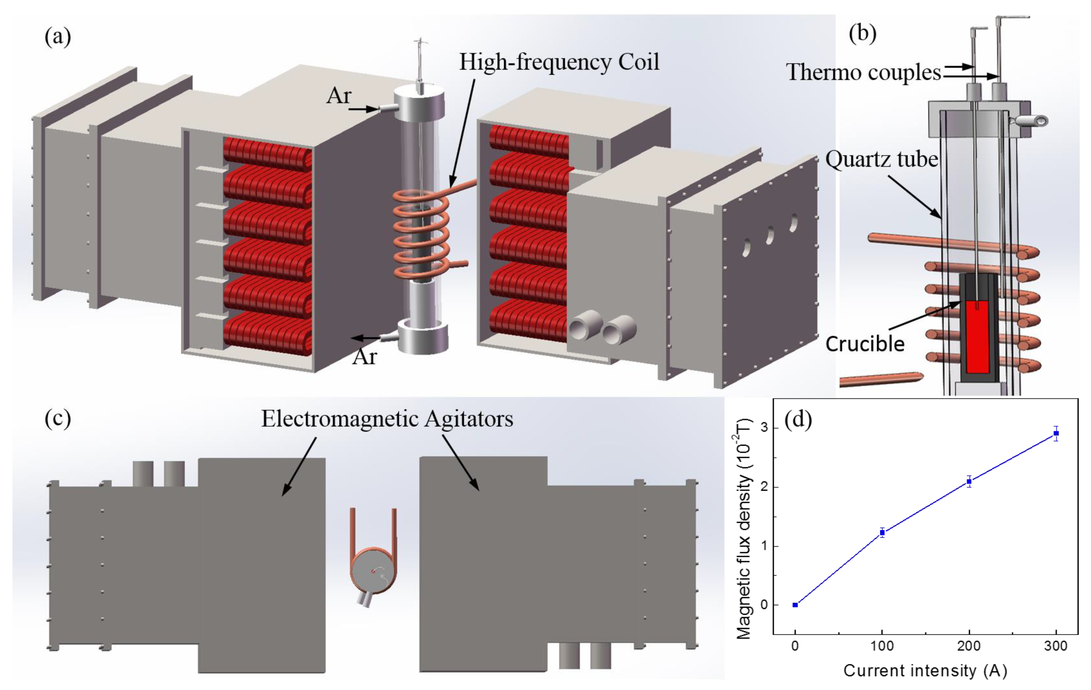
The microstructure of Cu-Co alloy depends on the liquid-liquid segregation, the peritectic reaction and the transition of the solid phase. These solidification behaviors are processed in a liquid matrix; hence they are inevitably influenced by the melt flow. This thesis used a two-side electromagnetic stirrer to generate a forced melt flow in Cu-15%Co alloy, and studied the effect of EMS on the fraction, distribution, and morphology of the Co-rich phase and the peritectic Cu-rich phase.
3. Results and Discussion
Cu-Co alloy has a metastable miscibility gap in the phase diagram which can result in the liquid-liquid separation and generate Co-rich droplets [
18]. Outside the miscibility gap, Co-rich phase is formed as dendrite. Both Co-rich droplets and dendrites were observed in microstructure presented by
Figure 2, in which the dark and bright regions were the Co-rich phase and Cu-rich phase, respectively. The spherical-shaped dark phase was transformed from the Co-rich droplet in the liquid-liquid separation, and the other dark phase was Co-rich dendrite. The droplets occurred in all the four experimental conditions (with different stirring currents: 0 A, 100 A, 200 A, and 300 A respectively), whereas the size and amount of these droplets were different. As the increase of current intensity of EMS, the volume fraction of Co-rich dendrites tended to increase, and the amount and size of Co-rich droplets both decreased.
The EMS also had a large impact on the morphology of the liquid spheres, the droplets were broken apart into smaller ones by the EMS.
Figure 2g,h present the backscattered electron (BSE) images of two Co-rich droplets with similar size, one is without EMS, the other is with an EMS of 300 A current. Both the two droplets underwent a secondary phase separation, leading to the occurrence of Cu-rich particles inside the Co-rich droplets. Without EMS, the tiny Cu-rich particles were distributed dispersively in the Co-rich droplet. Whereas, the Cu-rich particles turned to be large and irregularly shaped in the sample with EMS of 300 A current. Without stirring, the droplet appeared to be a stable sphere (
Figure 2g), indicating a steady state before it transformed into solid. With a strong stirring, the surface of the droplet was flushed by the melt flow and appeared to be unsteady, the droplet tended to be broken by the strong melt flow (
Figure 2h). In this way, the EMS broke apart large droplets and reduced the droplets size. Small droplets were merged by the dendrite nucleating and growing on them, thus EMS tended to reduce the fraction of Co-rich droplets.
We measured the cobalt concentration around the droplets using EDS, as shown in
Figure 2g,h. The concentrations of points 1–6 were 76.58%, 13.99%, 6.56%, 81.19%, 10.35%, and 4.63% respectively, indicating that EMS enhanced the concentration discrepancy between Co-rich and Cu-rich phase, which might be caused by an enhanced mass transport in a forced convection.
Figure 2i–k show the results of EDS mapping in the zone around a Co-rich droplet. The Cu-rich and Co-rich phase were distinctly identified. There were scanning points of Co element distributed in the Cu-rich matrix (
Figure 2k), which is denser near the Co-rich phase, and sparser in the region far from the droplet, such as the region closed to the upper right corner of the image.
A peritectic reaction is supposed to be generated between the Co-rich solid and Cu-rich liquid during the solidification process. The specimens were etched to show the region of peritectic Cu phase. There were two kinds of Cu-rich phase distinctly show in
Figure 2a–f, one was surrounding the Co-rich phase, the other was far from the Co-rich phase. We tested the composition of the two kinds of Cu-rich phase using EDS. The Cu-rich phase surrounding the Co-rich dendrites was identified to have a higher cobalt concentration in the range of 10.35–14.16% Co, which was the peritectic Cu-rich phase generated by the peritectic reaction. Another kind of Cu-rich phase was observed in the space between peritectic regions, which was measured to have a lower cobalt concentration in the range of 3.99–6.56% Co. This Cu-rich phase was transformed from residual melt after an incomplete peritectic reaction, indicating that only a part of Cu-rich liquid took part in the reaction. Since the peritectic reaction was generated between the Cu-rich liquid and the α-Co solid, such a reaction depended on the solute transport between the solid and the liquid phase, which could be influenced by the strong melt flow generated by EMS.
We have analyzed the XRD patterns of the Cu-Co alloys solidified in this experiment and found that EMS had no obvious effect on the XRD pattern.
Figure 3 presents XRD patterns of the specimen without and with EMS. The XRD results revealed that the Co-rich phase in the ingot is α-Co, which has not transformed into ε-Co from face-centered cubic (f.c.c.) to hexagonal close-packed structure (h.c.p.) through the allotropic transformation. Both the droplets and dendrite consisted of α-Co phase. We measured the composition of different Co-rich phases using EDS, the result revealed that Co-rich dendrites contained 82.79–93.44% Co, and Co-rich droplets contained 76.58–84.19% Co. The average cobalt concentration of spherical Co-rich particles was lower than that of the Co-rich dendrites.
The morphology of α-Co phase in the solidification structure depended on several different reactions.
Figure 4 shows a phase diagram of Cu-Co alloy together with its schematic diagram of the solidification process, in which an arc-shaped metastable miscibility gap exists below the liquidus line. When the liquid Cu-Co is cooled into this region, it separated into Co-rich liquid (L
1) and Cu-rich liquid (L
2). The solidification routes of Cu-Co alloy have been studied by many researchers [
29,
30,
31,
32]. A metastable miscibility gap exists below a certain temperature resulted in the separation of the melt into two liquids [
31]. Isolated droplets of minority liquid phase coarsen and grow in a spherical shape to minimize surface energy [
30]. Owing to recalescence, the droplet-shaped particles have a chance to coexist with the α-Co dendrites in the microstructure [
32].
The specimens in all the four experimental conditions contained spherical Co-rich phase in the microstructure, indicating that the melt has entered the miscibility gap. The cooling rate was measured to be 53 K/s, and the undercooling was estimated to be about 120 K (The minimum undercooling for liquid phase separation of Cu-15%Co alloy is 113 K according to
Figure 4). This undercooling might be caused by the boron oxide layer on the melt surface, which has an effect to absorb the tiny impurity particles in the melt. Thus, it might suppress the nucleation and enhance the undercooling. There was no significant discrepancy of undercooling between different EMS conditions. The solidification process included three stages mainly: (a) Liquid-liquid separation prior to solid nucleation. When the melt was cooled below the metastable miscibility gap, phase separation initially appeared as many small Co-rich droplets dispersed within the Cu-rich liquid. The droplets of the minority phase migrated in the melt under the effect of gravity, the interface tension, and the melt flow [
33]. The droplets impinged upon one another, and further resulted in the increase of droplet size. (b) Recalescence and formation of Co-rich dendrites. The heat released by the liquid-liquid separation raised the liquid temperature, both L
1 and L
2 were out of the region of the miscibility gap and the system was in a miscible state again. L
1 Co-rich droplets tended to transform into α-Co solid phase and released more heat, which further increased the liquid temperature. This process due to heat release is recalescence. If the temperature of the melt was above the miscibility gap again, Co-rich dendrites were forming in the matrix, which grew along with the spherical α-Co phase. The solidus line has a higher cobalt fraction than the immiscibility boundaries of L
1 liquid, therefore α-Co dendrites tend to have a higher cobalt concentration than the Co-rich droplets. (c) Peritectic reaction. When the liquid temperature reached the peritectic temperature, a peritectic reaction took place and a peritectic Cu-rich solid phase occurred between the α-Co phase and the liquid Cu-rich matrix. Since the peritectic Cu-rich phase was a solid phase and the diffusion was relatively slow, the solid Cu-rich phase created a diffusion barrier and the peritectic reaction proceeded at an ever-decreasing rate. In this experiment, there was some residual Cu-rich liquid that had not participated in the peritectic reaction, which solidified into the residual Cu-rich phase with a different cobalt concentration compared with the peritectic Cu-rich phase (
Figure 2a–f).
Figure 5a presents the relation between the current intensity and the fraction of the peritectic Cu-rich phase to the whole Cu-rich matrix. The fraction increased with increasing current, indicating that the peritectic reaction was accelerated by the EMS, which was caused by the enhancement of mass transport in a forced melt flow.
Figure 5b shows the fraction of spherical Co-rich particles changed with the current intensity of EMS. The volume fraction decreased with increasing current intensity, indicating that a strong melt flow tended to reduce the fraction of Co-rich droplets during solidification. As discussed above, the large droplets were broken up by the forced flow into smaller droplets and later merged by the growing dendrites.
Figure 5c shows the statistic of the dendrite length under different experimental conditions. EMS broke up long dendrites and reduced the dendrite size. As the stirring current increased, the dendrite length tended to have a higher probability density in the range of 20–180 μm, which corresponded to small size dendrites or fragments, indicating that some dendrites were broken into fragments by the EMS. However, the dendrite lengths in all the four experimental conditions have similar distribution range, which meant there were still many long dendrites keeping unbroken even in a forced flow. The peak position in
Figure 5c was not regularly moved left with increasing current intensity. The region of 90–150 μm was around the peak position and included most of the short dendrites, which had a smaller possibility to be broken by the EMS with current smaller than 200 A. Instead, the dendrite growth tended to be accelerated by the high solute transport under the forced flow. This might move the peak position slightly to the right side. However, some dendrites in this region tended to be broken by the EMS with a current of 300 A, which moved the peak to the left side.
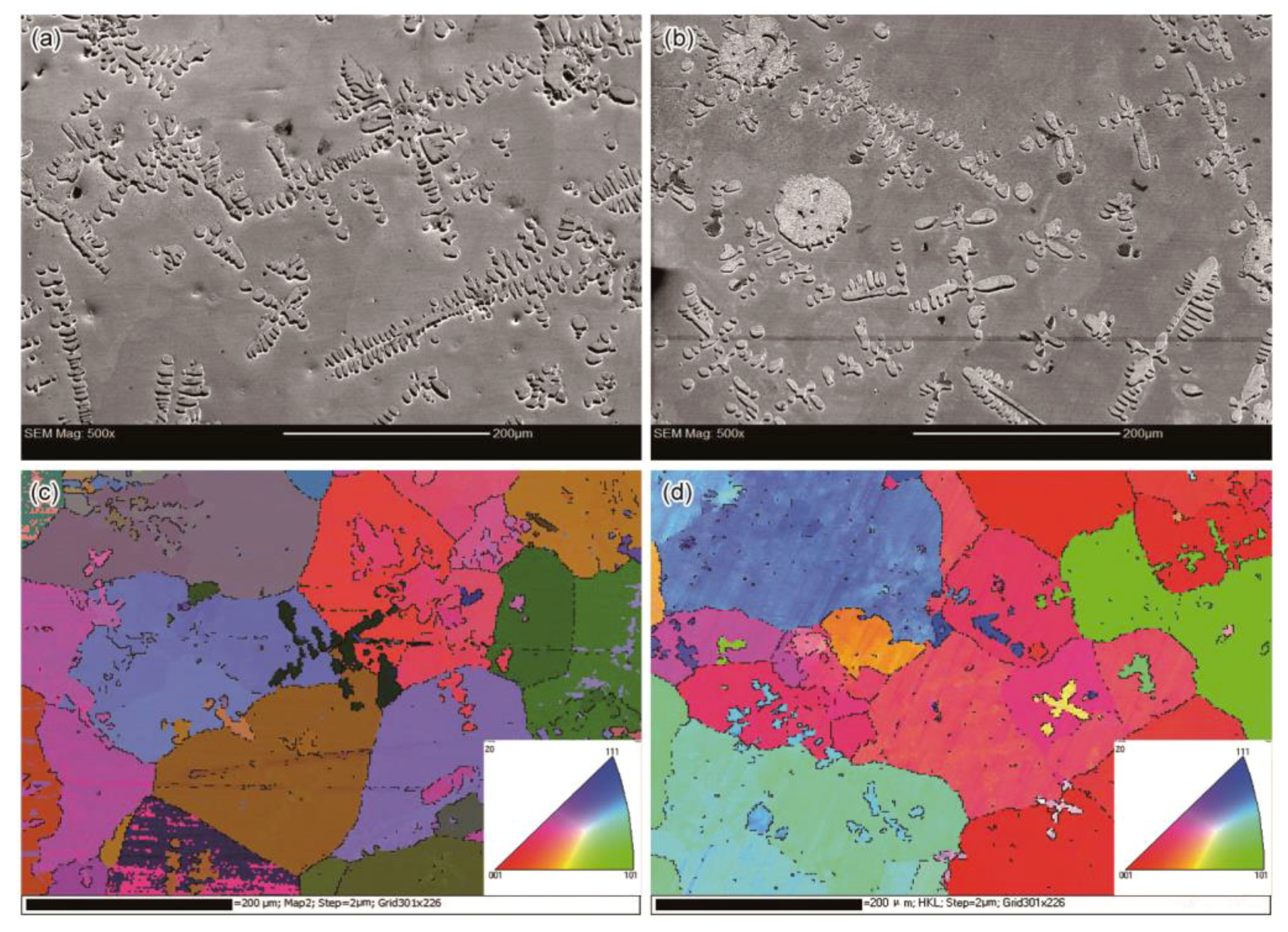
Figure 6 shows the images of electron backscatter diffraction (EBSD) and the corresponding FESEM images of the specimens with and without EMS. Both the FESEM images contained multiple dendrites, some of which appeared to be equiaxed dendrites or fragments. Several long dendrites in the 0 A specimen tended to link closely with each other, while the dendrites in the 200 A specimen were distributed dispersively. Since the Cu-rich phase was initially generated around the α-Co phase thorough peritectic reaction, the amount and size of α-Co dendrites and droplets tended to affect the formation of Cu-rich grains. As discussed above, the peritectic Cu-rich phase surrounded α-Co dendrites and droplets by nucleating and growing on them. Later, the residual melt also transformed into the solid state and surrounded the peritectic Cu-rich region. As revealed by the EBSD results (
Figure 6c,d), the Cu-rich matrix was composed of grains with different orientations. The peritectic and residual Cu-rich phases were of the same crystal orientation and formed one grain when they surrounded one dendrite. Because the small α-Co dendrite fragments distributed dispersively in the 200 A specimen, there were some small grains forming around these α-Co fragments.
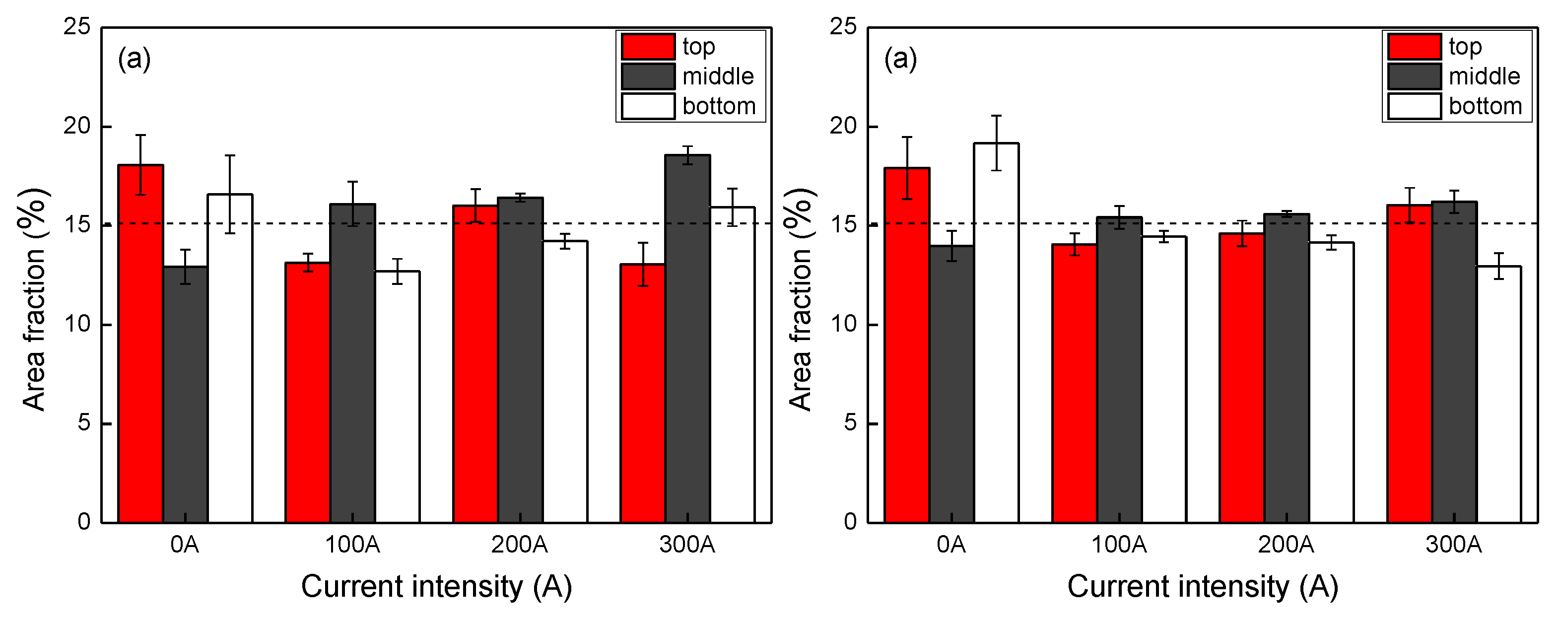
Although the density difference between cobalt and copper is small, there is still a possibility of macrosegregation during solidification of Cu-Co alloy. We analyzed the macrosegregation by measuring the volume fraction of Co-rich phase (area fraction in the microstructure) in different positions, as shown in
Figure 7. Without EMS, the ingot had a higher cobalt fraction in the top and bottom, and a lower fraction in the middle part. On the contrary, the middle part tended to have a higher cobalt fraction when the EMS was applied. By comparing the fractions in different specimens at the 15 mm height from the ingot base, we found that the cobalt area fraction increased with increasing stirring current in both the central and edge part.
Figure 7a compares the phase fraction in the central part of different specimens. The discrepancy in the area fraction with different height tended to be small when the stirring current was set as 200 A. The discrepancy in the edge part was also small when the stirring current was 100 A or 200 A, as shown in
Figure 7b. By comparing the fraction discrepancy in the radial direction, we also found the value having the smallest discrepancy between the center and edge part when the stirring current was 200 A. The EMS tended to reduce the macrosegregation in both the vertical and radial direction of the ingot when the stirring current was set as 100 A and 200 A. However, when the current intensity was enhanced to 300 A, the enlarged discrepancy at different positions indicated a worse macrosegregation.
As revealed by
Figure 2, the Cu-rich phase closed to the α-Co phase was generated by the peritectic reaction, which should have a higher cobalt concentration than the Cu-rich phase transformed from the residual melt.
Figure 8 shows the results of EDS line mapping of element cobalt along a dendrite arm and the surrounding Cu-rich phase. There was an instant drop of cobalt concentration when the line mapping reached the Cu-rich part, which was 115 counts for the specimen without EMS and 125 counts for the specimen with 200 A EMS, indicating that EMS enlarged the concentration discrepancy between Co-rich and Cu-rich phase. In the Cu-rich phase, the cobalt concentration continued to drop in the direction far away from the Co-rich phase. There was a drop of 5 counts to the average level within a short distance in the specimen without EMS. However, the drop was 14 counts, but the concentration decreased monotonically within a larger distance in the 200 A specimen, indicating an enlargement of the region of peritectic Cu-rich phase. The EMS enhanced mass transport through the liquids, which helped to adjust the compositions of the two liquids. Therefore, the two liquids followed the immiscibility boundaries and had a larger composition discrepancy compared with the case without EMS. The high mass transport also accelerated the peritectic reaction, resulting in the enlargement of the peritectic Cu-rich region.


