Article

Change of the Chemical and Mineralogical Composition of the Slag during Oxygen Blowing in the Oxygen Converter Process

Technical University of Kosice, Faculty of Materials, Metallurgy and Recycling, Institute of Metallurgy, Park Komenskeho 14, 04001 Kosice, Slovak
*
Author to whom correspondence should be addressed.
Metals 2018, 8(10), 844; https://doi.org/10.3390/met8100844
Submission received: 28 September 2018 / Revised: 12 October 2018 / Accepted: 16 October 2018 / Published: 18 October 2018
(This article belongs to the Special Issue Refining and Casting of Steel)

Abstract

:
The article presents the results of the investigation of changes in the chemical and mineralogical composition of slag during steel production in a blown oxygen converter. This process was monitored using the slag samples that were collected during the period when oxygen blowing into an oxygen converter was interrupted. The slag samples were collected after 150 s (2.5 min), then after 5, 8, 11, and 24 min of oxygen blowing, and in minute 27 when oxygen blowing was terminated. The sampling was carried out within five consecutive melting processes. The article presents and documents the changes in the contents of CaO, CaO (free), Fe (total), FeO, SiO2, and in the basicity of the slag during oxygen blowing. It also provides the characteristics of individual structural components formed during oxygen blowing and a detailed description of the lime assimilation process, including the formation of the final structure of the slag, consisting of dicalcium silicate (2CaO·SiO2), tricalcium silicate (3CaO·SiO2), RO-phase, and calcium ferrites (2CaO·Fe2O3). The results of the investigation of the changes in the chemical composition of the slag during oxygen blowing in an oxygen converter were compared with the changes in the structural composition of the slag.

1. Introduction

Metallurgical slags play an important role in the processes of steel production and treatment. The knowledge of the formation and development of chemical and mineralogical properties of steel slags is essential. Steel production in oxygen converters is primarily characterised by a high rate of individual operations and this must be considered when determining the slag production rate. Therefore, it is important to know the key factors influencing the rate of slag formation. Additionally, slags must have the required physical and chemical properties to fulfil its purpose during the steel production. And, last but not least, the final chemical and mineralogical composition of slag has a significant impact on its final properties and, hence, its further utilization. Until now, very few scientific papers have dealt with these issues at such a complex level. For the first time, the chemical and mineralogical compositions of steelmaking slags were directly linked.
The main factors that determine the rate of slag formation are the contents of oxides of iron and manganese in the slag, the temperature of the steel, and the conditions under which the lime is added [1]. When the slag formation is delayed, corrosion of the furnace lining increases, oxidised impurities are not completely absorbed, and lime utilization is low. The slag formation process is a key factor affecting the quality of the produced steel and the output of the production process as such.
The important roles of slags during the steel production are described by the author [2]. Steelmaking slag acts as a sink for impurities during refining of steel, and it controls oxidizing and reducing potential of the bath during refining through FeO content. Slag prevents the passage of nitrogen and hydrogen from the atmosphere to the liquid steel in the bath, provides protection to the liquid steel from re-oxidation, and insulates the liquid bath and reduces thermal losses.
In order to control the slag regimen in an oxygen converter, it is important to understand the process of formation of the structure and composition of slag during the steel production. This process must also be studied in relation to the developmental trends in the field of steel production and a growing number of variables.
The importance of converter slag as dephosphorization and desulphuration media has ceased with implementation of special pre- and post-converter treatments. The transfer from top blowing to combined blowing converters has decreased the amount of slagged iron that, together with the tendency towards lower silicon and manganese contents, has decreased slag to steel ratio. Still, the control of slag forming and behaviour during the blow is of great importance [3].
The generated compositions and amounts of slag will depend on the process in which the slag is formed and on the raw materials used in the process, e.g., iron input and fluxing ingredients, such as burnt lime, governed by the proportions of materials required for an effective process [4].
Slag in a BOF (basic oxygen furnace) is heterogeneous and always contains some entrained gas bubbles and solid material (either un-dissolved or precipitated) [5].
Knowledge of the chemical, mineralogical, and morphological properties of steel slags is essential because their cementitious and mechanical properties, which play a key role in their utilization, are closely linked to these properties [6].
The authors of paper [7] reported physical and chemical characteristics of the converter steel slag, as well as its comprehensive utilization by means of internal and external recycling. The major structural phases of the converter steel slag mainly include dicalcium silicate (2CaO·SiO2), tricalcium silicate (3CaO·SiO2), RO-phase (a solid solution of CaO-FeO-MnO-MgO), and calcium ferrite (2CaO·Fe2O3). There are great differences in Vickers hardness between individual mineral phases of the converter steel slag.
At present, after the separation of the metallic fraction that is recycled directly in a metallurgical plant, the processing of the converted slag may be divided into three main trends. Within the first one, the converter slag is used in the building industry [8,9,10,11]. According to the second trend, steel slag is used in agriculture [12]. The third trend shows that the steel converter slag is added directly into a blast-furnace, agglomeration, or steel charge [13,14].
The purpose of the present article was to analyse the process of slag formation and development in a top-blown oxygen converter on the basis of the changes in the chemical and mineralogical composition. This process may be best examined if the slag samples are collected in the period when the oxygen blowing is interrupted. The slag samples were collected after 150 s (2.5 min), then after 5, 8, 11, and 24 min of oxygen blowing, and after the oxygen blowing was terminated in minute 27. For this purpose, the sampling was carried out during five consecutive melting processes (A, B, C, D, E) in a top-blown, 190-tonne oxygen converter. The total melting time was 46 min while the blowing time was 27 min in all the melting processes.

2. Materials and Methods

The charge used in the oxygen converter (VSZ a.s., Kosice, Slovakia) consisted of pig iron and steel scrap, in approximately identical quantities in all melting processes. The slag-forming additives were lime and dolomitic lime. In the case of Melting Processes D and E, the quantities of the added slag-forming additives were identical. In Melting Process C, the quantities of lime were approximately 25% higher. In Melting Process B, the percentage of slag-forming additives was the highest, and in addition to lime and dolomitic lime, magnesite was used as well. In Melting Process A, a portion of the lime was replaced with the demetallized converter slag. The slag-forming additives were added into the oxygen converter gradually. The first dose was always added in the beginning of oxygen blowing and the second dose before minute 2 of oxygen blowing. In Melting Process B, it was necessary to add an extra dose of slag-forming additives due to the unsatisfactory result of the pre-test chemical analysis. The quantities of the charged raw materials used in the steel production in individual melting processes and the doses of slag-forming additives are presented in Table 1.
The chemical analysis of the collected slag samples was carried out in the accredited laboratory by X-ray quantometer RIGKU (VSZ a.s., Kosice, Slovakia), and was supplemented with the identification of the slag basicity (B = CaO/SiO2), as well as the analysis of free lime, as presented in Table 2. The content of free lime was determined applying the method of chemical analysis. This method uses the selective dissolution of free lime in the mixture of sugar and alcohol, and the subsequent determination through the titration with hydrochloric acid. The described methodology is typically used when performing an analysis of free lime directly in a metallurgical plant. However, this methodology is not standardised. Additionally, slag samples were treated applying a standard method, that is, grinding and polishing, in order to prepare metallographic scratch patterns, which were subsequently examined using a NEOPHOT 32 optical microscope (Technical university of Kosice, Kosice, Slovakia). Thus, individual structural components and their morphology were observed and photographically documented.
The performed analyses also included the EDX microscopy analysis that was aimed at qualitative as well as quantitative confirmation of the percentages of individual structural phases present in the slag. This EDX analysis was carried out using a Joel JSM-7000F scanning electron microscope (SAV, Kosice, Slovakia). This analysis was applied to a complete series of slag samples collected from the Melting Process D. The purpose thereof was to predict individual structural components of the slag. The analysis and the microscopic observation facilitated acquiring the best possible understanding of the development of the slag structure in the convertor.
The experimental melting processes also included the sampling during the period when oxygen blowing was interrupted, always after minute 8 and 24, and in minute 27 when oxygen blowing was terminated. Also, the temperature and activity of oxygen in the metal were measured. The chemical composition of the metal, identified in the accredited laboratory by an ARL 8800 spectrometer, the temperature of the metal, and oxygen activity by a CELOX immersion probe are listed in Table 3.

3. Results

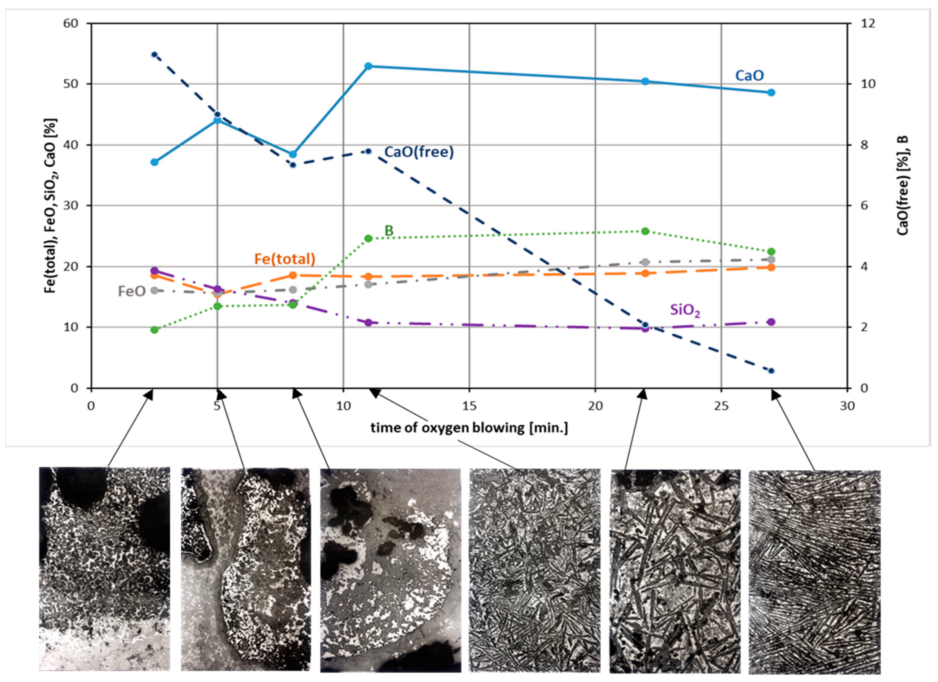
3.1. Changes in the Chemical Composition of Slag during Oxygen Blowing

In the beginning of oxygen blowing, the steel scrap represented the lowest layer inside the converter and it was covered with liquid raw iron with the temperature of 1350 °C. Subsequently, the first dose of slag-forming additives was added and the oxygen jet was triggered. The second dose was added gradually, before minute 2 of oxygen blowing. The melting temperature of the pure lime is 2570 °C. The dissolution as such began after the termination of the passive period that consisted of heating the melt frozen on the lime parts. It was, therefore, necessary, in the beginning of oxygen blowing, to increase the temperature of the bath, as soon as possible, particularly in the upper section of the converter where the parts of undissolved lime, covered with the frozen melt, were floating on the level of the molten metal. Therefore, in the beginning of oxygen blowing, the so-called “soft blowing” is always applied. In this case, the oxygen jet was placed above the bath level, and the oxygen flow rate was reduced. In the beginning of oxygen blowing, oxygen from the oxygen jet in the impact zone was dissolved. The bath temperature rapidly increased. During oxygen blowing, the temperature near the oxygen jet reached over 2000 °C. Following the melting of the slag phase, the oxygen blowing mode changed into the so-called “hard blowing”. The oxygen jet was shifted lower towards the bath level and intensity of oxygen blowing was increased while the entire content of the bath was intensively stirred and oxidised.
The changes in the chemical composition of the slag and in the slag basicity during oxygen blowing in the top-blown oxygen converter for individual melting processes are listed in Table 2. The beginning of blowing was accompanied with intensive oxidation of the upper section of the bath. Temperatures gradually increased due to the running exothermal reactions. Oxygen began to dissolve in the metal bath and this was followed by the oxidation of iron and other additive components. The first to oxidise was silicon due to its strongest affinity for oxygen. As shown in Table 3, the average value of the silicon content in raw iron was 0.808%. After 8 min of oxygen blowing, the silicon contents decreased, in all the melting processes, down to 0.010%. As a result of a low percentage of dissolved CaO and a high concentration of SiO2 in the slag, very aggressive acidic slag was formed in the beginning of oxygen blowing. The slag basicity after 2.5 min of oxygen blowing ranged from 1.42 to 1.94. During oxygen blowing, there was an increase in the quantity of slag from the oxides that are transferred into the slag and the slag-forming additives were gradually dissolved. The basicity of the slag increased. At the end of the refining process, the basicity values ranged between 4.1 and 4.55. In Melting Process B, the final basicity value was 5.15; this was caused by adding another dose of slag-forming additives that were added due to the unsatisfactory chemical composition of the metal at the pre-test. With the increasing percentage of the dissolved lime during oxygen blowing, the content of CaO (free) proportionally decreased. Nevertheless, this process is imperfect and at the end of oxygen blowing the final slag contains undissolved lime parts in the quantities representing 0.58% to 0.95%. In Melting Process B, the final content of free lime reaches the value of as much as 1.77%, as a result of adding the third dose of slag-forming additives. In the details of the study, it is possible to find unassimilated pieces of lime in the all samples. For example, Figure 1 shown free lime in the slag within Melting Process B, which is visible even to the naked eye.
The content of free lime in steel slag is the key factor that hinders potential applications of metallurgical slag in the building industry. If the free lime is not stabilised, it is hydrated at sites where it comes into contact with the surrounding atmosphere and its volume increases, thus causing the volumetric instability and the consequent decomposition of the slag, according to Equation (1):
  CaO ( 1 cm 3 ) H 2 O Ca ( OH ) 2   portlandite ( 1.92 cm 3 ) CO 2 CaCO 3 ( 2.14 cm 3 ) calcite   +   H 2 O  
The content of SiO2 in the slag reached the highest values in the beginning of oxygen blowing (18.06% to 19.30%). Due to the fact that silicon has the strongest affinity for oxygen, the majority portion of silicon oxidises within 8 min of oxygen blowing. As a result of the gradual dissolution of lime, transfer of other oxidised admixtures into the metal, and an increase in the total quantity of slag, the content of SiO2 in the slag gradually decreased during oxygen blowing. At the end of oxygen blowing, the content of SiO2 in the slag represented 9.8% to 12.24%.
In the beginning of oxygen blowing, the content of total iron in the slag was rather high, ranging from 18.54% to 27.96%. This was caused by the fact that the surface of the bath was highly oxidised due to the “soft blowing”, which resulted in oxidation of Fe from the metal bath into FeO and its transfer into the slag. Very intensive mixing of the surface parts of the bath also resulted in a higher content of metallic Fe in the slag in form of drops; this corresponds to the high content of Fe (total). During oxygen blowing, when the operation mode was switched to “hard blowing” and after increasing the quantity of the slag, the percentage of Fe (total) decreased as a result of the reverse reduction of FeO from the slag into the bath. The lowest values of Fe (total) and FeO contents in the slag were observed approximately between minutes 8 and 11 of oxygen blowing. At the end of oxygen blowing, when the temperature of the metal bath was high and the admixture components were oxidised, the oxidation of Fe into FeO ran again in the bath and resulted in the transfer thereof into the slag. At the end of the refining process, Fe (total) ranged from 15.00% to 21.44%.

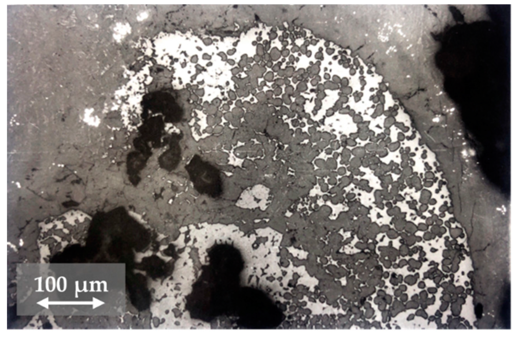
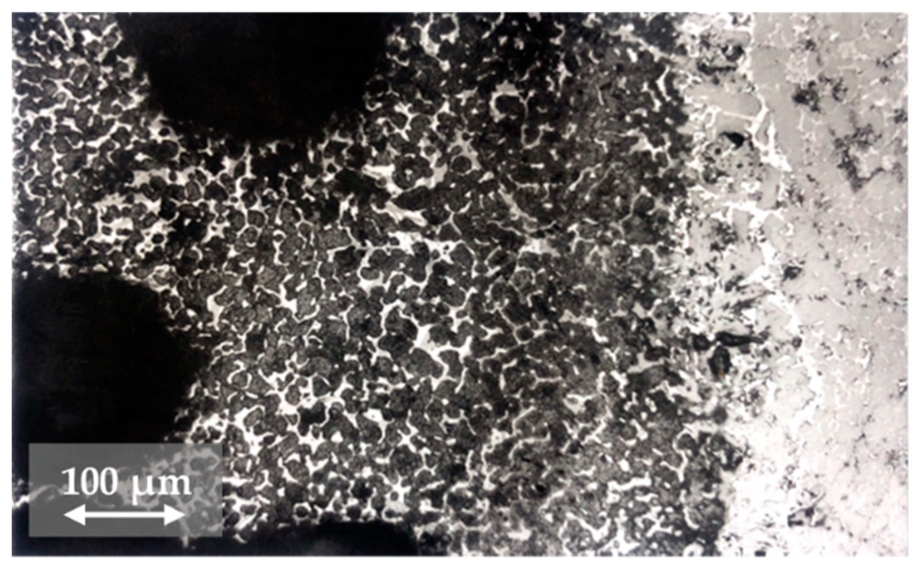
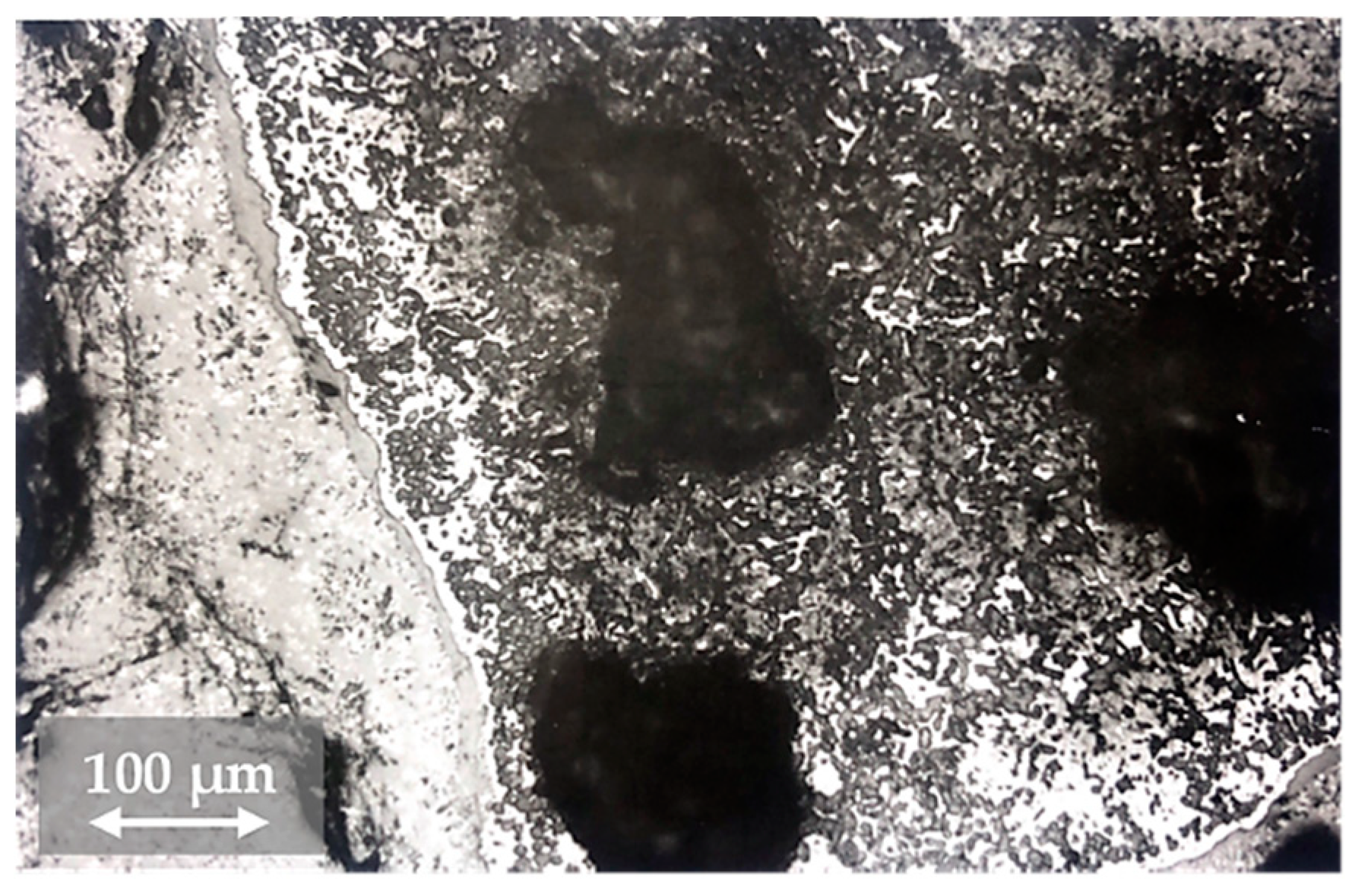
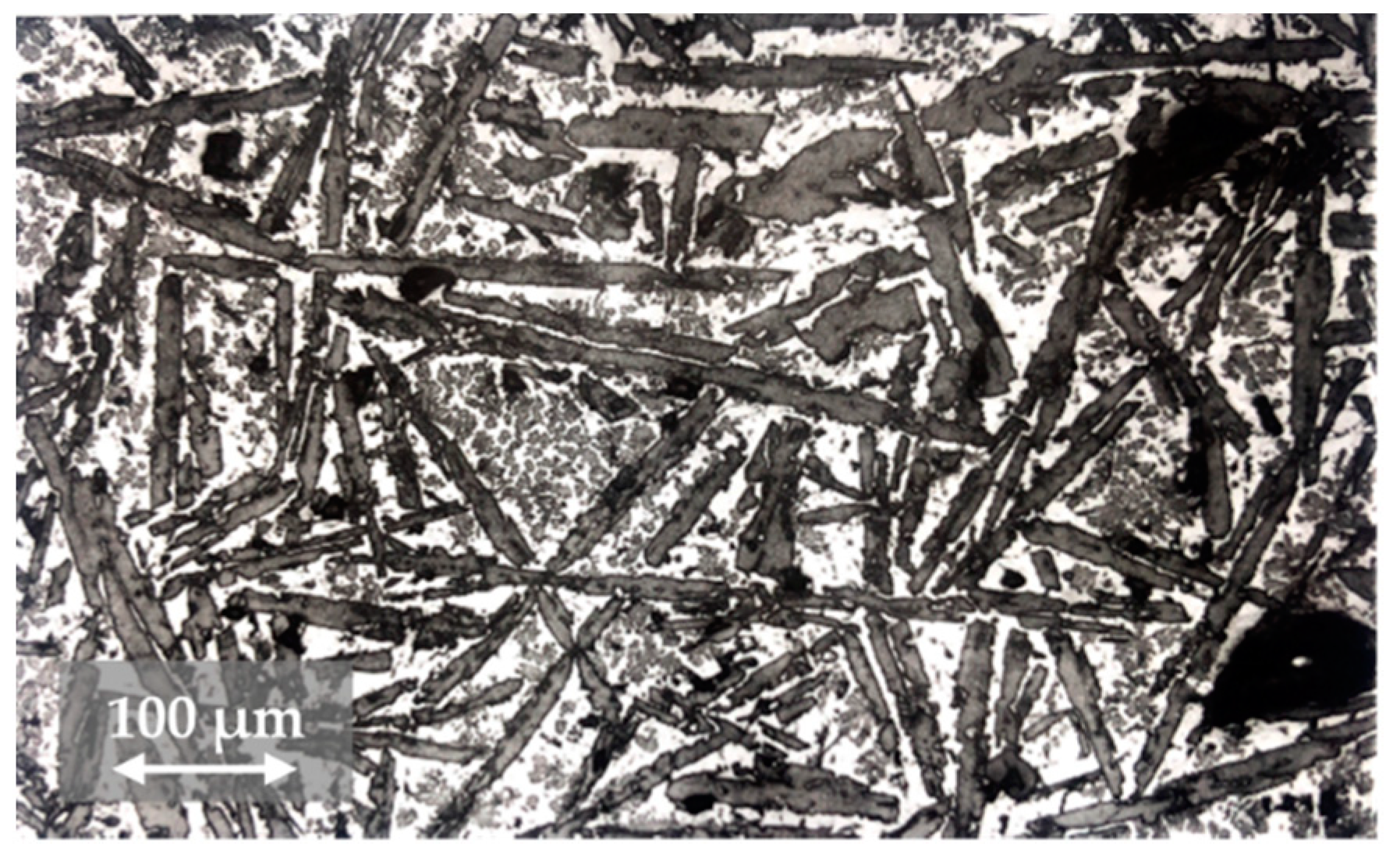
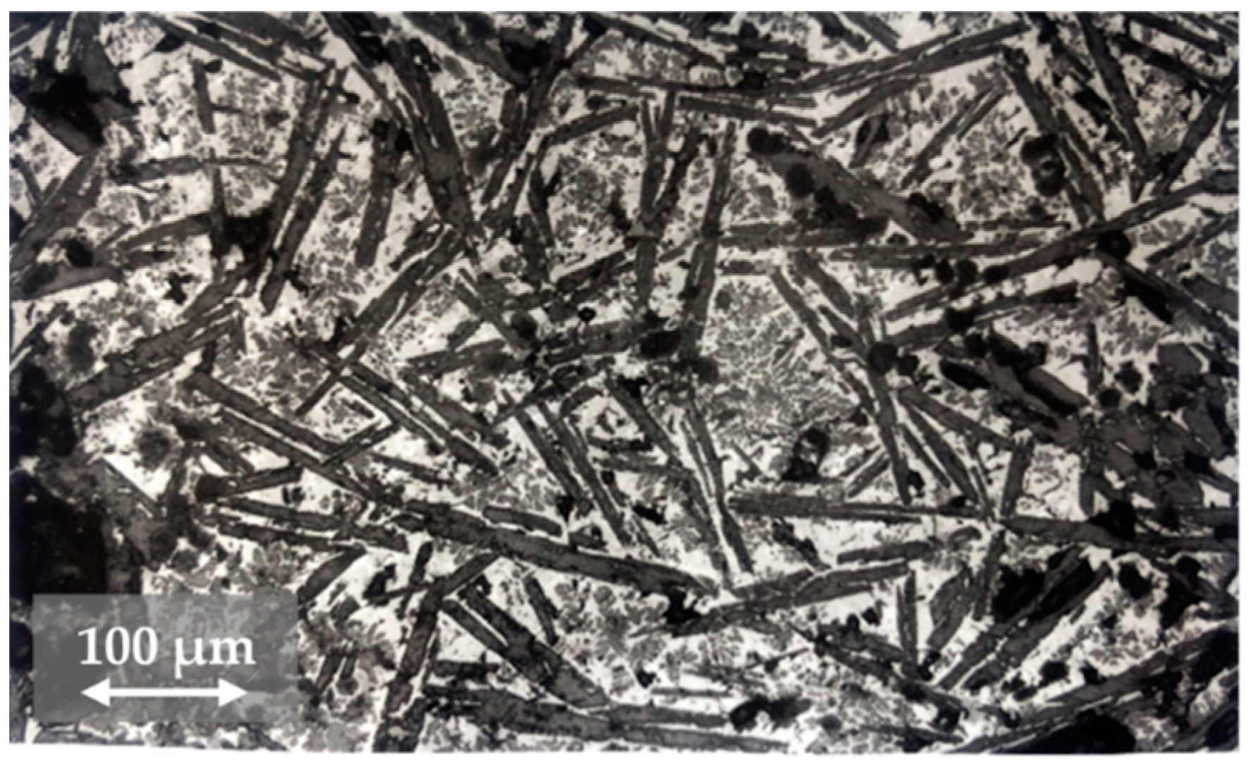
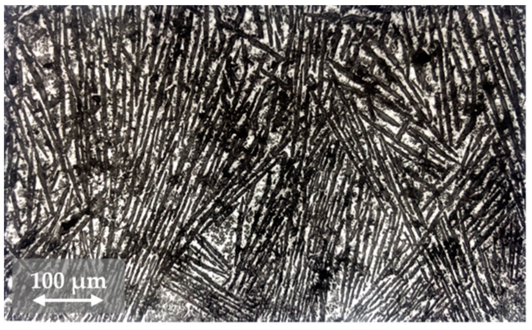
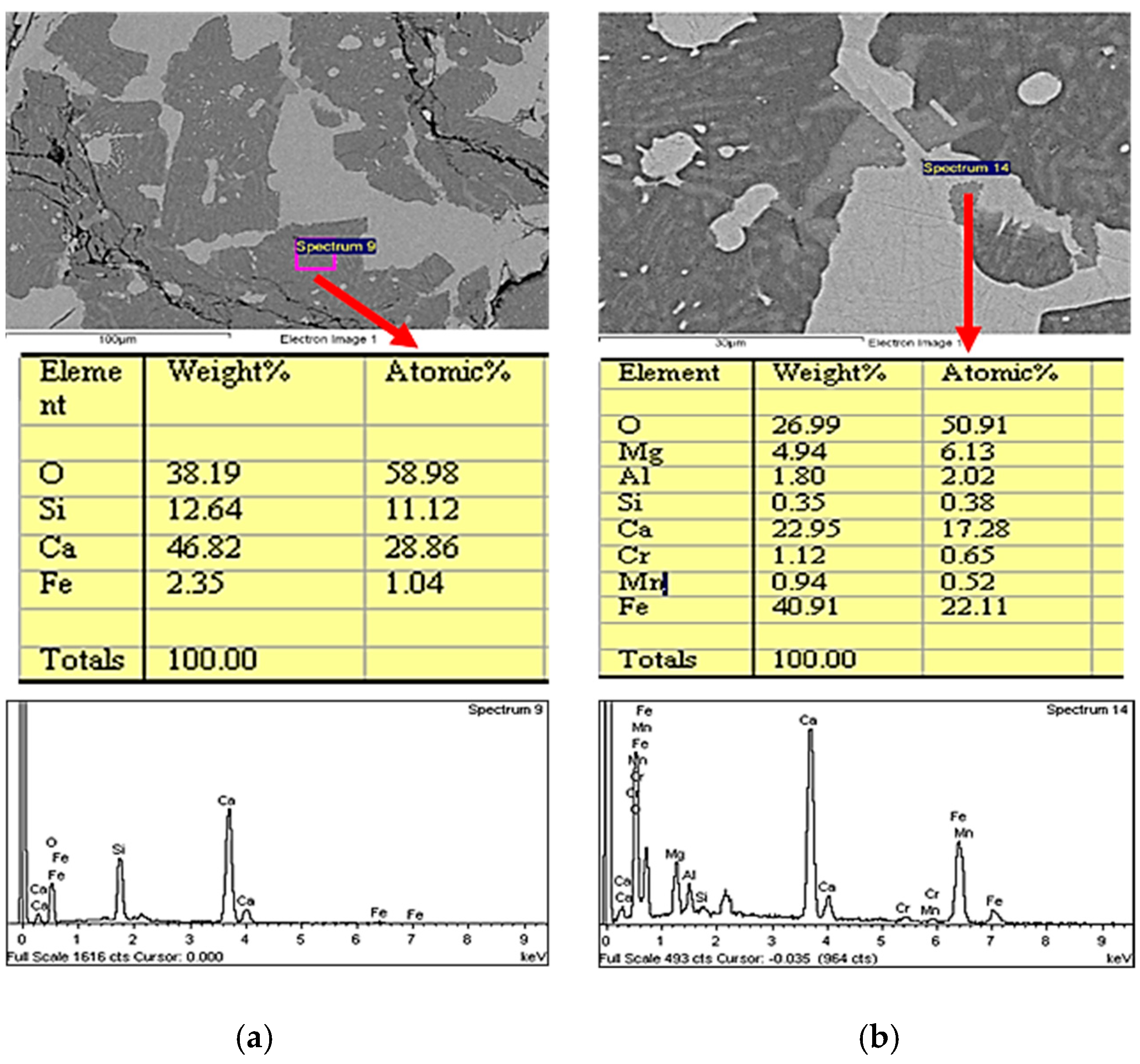
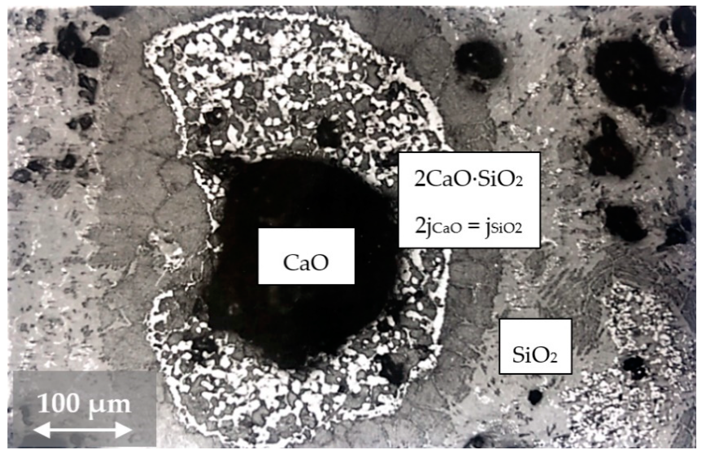
3.2. Changes in the Mineralogical Composition of Slag during Oxygen Blowing
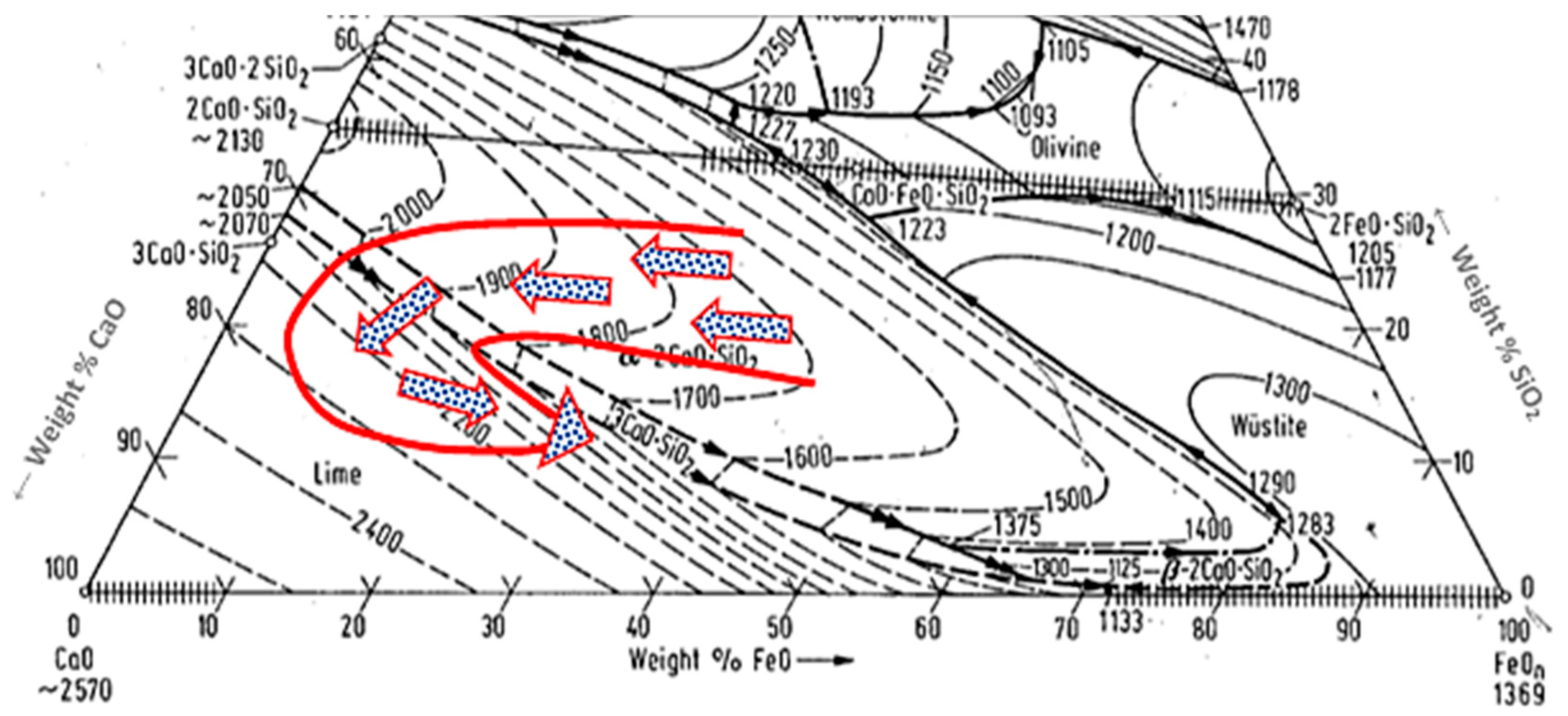
The slag samples collected 2.5 min after the beginning of oxygen blowing reflected the status immediately after the slag-forming additives were added into the converter. Majority of slags were of the glossy character that was caused by the presence of silicon oxide in the slag. In the diffractogram of the X-ray diffraction analysis, the dominating structural patterns were the lines of calcium oxide or calcium hydroxide that were formed as a result of CaO hydration in the sample. Sporadically, monticellite 2(FeO,MnO,MgO,CaO)·SiO2 and dicalcium silicate 2CaO·SiO2 precipitated. Figure 2 presents a lime part in the primary slag, detected 2.5 min after the beginning of oxygen blowing. The figure clearly shows the beginning of the infiltration of a lime part by the slag, as well as mostly glassy character of the slag surrounding the lime part, and the beginning of the formation of dicalcium silicate precipitation front around the lime part.
In the slag samples collected after minute 5 of oxygen blowing, the basic structural component was again the free lime, in form of calcium hydroxide at the time of the X-ray diffraction analysis. In addition to the free lime, the structure also comprised of dicalcium silicate 2CaO·SiO2 and, in a small amount, also calcium ferrites CaO·Fe2O3. Lime parts lay inside the glassy silicate matrix. This stage was characterised by the formation of a dicalcium silicate margin around the lime part and a high degree of infiltration of the lime part by the slag, including the initial formation of calcium silicates and RO-phase that consisted of free oxides (Fe,Mn,Ca,Mg)O inside the lime part. Figure 3 clearly shows the formation of dicalcium silicate margin around the lime part in the glassy silicate slag.
In the slag samples collected after minute 8 of oxygen blowing, there was a significant decrease in the number of pieces of unassimilated lime, or more precisely, reduction of their sizes. Dicalcium silicate became the basic structural component. As compared to the previous group of slags, collected after minute 5 of blowing, there was a slight increase in the content of calcium ferrite CaO·Fe2O3. The structure also contained the primary silicate slag that is characterised by its glassy character. On the basis of the performed analyses we can state that approximately in minute 8 of the refining process the final structure of the slag began to form. Figure 4 shows the lime part in the stage preceding the total assimilation.
The slag samples collected after minute 11 of oxygen blowing contained only the residues of unassimilated lime. The fact that even more calcium oxide was transferred into the slag from the assimilated lime resulted in the transformation of a part of dicalcium silicate into tricalcium silicate, Equation (2):
2CaO·SiO2 + CaO → 3CaO·SiO2
The morphology of calcium silicates was different at various structure sites; some sites were present with globular particles, at some sites the predominating components were acicular formations, as shown in Figure 5.
The structure of slag samples collected after minute 24 was rather homogenous as to their morphology. The slag contained tricalcium silicate, dicalcium silicate, RO-phase, and calcium ferrites. The product of dephosphorisation, 3CaO·P2O5, was bound to dicalcium silicate; the product of desulphurisation, CaS, was bound to calcium ferrites. The structure still contained a certain portion of unassimilated lime, probably originating in the last dose of slag-forming additives. However, it was not in the form of pure calcium oxide, but the solid solution of CaO-FeO containing 10% FeO. The formation of this solid solution was accompanied with the oxidation of iron in the last stages of the refining process. A typical appearance of such structure is presented in Figure 6. It contains needles of tricalcium silicate, dicalcium silicate, as well as RO-phase and calcium ferrites located between the arms of the needles.
Through a visual assessment it was possible to observe dicalcium silicate in irregular formations, representing globular, acicular and irregular formations. As the lime gradually dissolved, the slag became even more intensively saturated with the lime. Subsequently, dicalcium silicate transformed into tricalcium silicate that was predominantly separated out in the acicular form.
In the slag samples collected after the oxygen blowing was terminated, there was no change in their structural composition, as compared to the samples collected after minute 24 of oxygen blowing. The structure of the slag was very homogenous, see Figure 7. Due to intensive mixing in the bath, as well as further dissolution of lime in the slag structure, the majority component was tricalcium silicate. The percentage of dicalcium silicate, separated out in the slag mainly in form of irregular formations, was gradually decreasing. The percentage of tricalcium silicate, which tends to separate out in acicular formations, was increasing. Due to intensive mixing, the homogeneity of the slag was increasing with longer refining times.
Predominating components were tricalcium silicate, dicalcium silicate, RO-phase and calcium ferrites. The structure of the slag also contained a small amount of unassimilated lime. The presence of dicalcium silicate, calcium ferrites in the final slag in Melting Process D is presented in Figure 8.

4. Discussion

As mentioned above, five consecutive melting processes were analysed. In all cases, the same grade of steel was produced. The charge used in the oxygen converter consisted of pig iron and steel scrap in approximately identical quantities in all melting processes, where lime and dolomitic lime were used as the slag-forming additives. In Melting Process C, the quantities of lime were approximately 25% higher. In Melting Process B, it was necessary to add an extra dose of slag-forming additives due to the unsatisfactory result of the pre-test chemical analysis. In Melting Process A, a portion of the lime was replaced with the demetallized converter slag. The amounts and types of the added slag-forming additives did not have any significant effect on the formation of slag, or on its chemical and mineralogical composition.
The rate of slag formation is determined by the rate of dissolution of lime, the melting temperature of which is, as mentioned above, 2570 °C. During the production of steel in an oxygen converter, such temperature could not be achieved in the entire melt content. Dissolution of CaO was therefore rather slow. After the oxygen jet was triggered, oxidation of the bath began. The first to oxidise was silicon; it reacted with CaO under concurrent formation of 2CaO·SiO2 while its melting temperature is 2130 °C) [15]. The slag formation was very positively affected by mixed oxides that were formed in the FeO-MnO-CaO, CaO-Fe2O3, and CaO-P2O5 systems that have lower melting temperatures than CaO. An example of dissolving CaO in the primary slag is shown in Figure 9.
There was a gradient of CaO activity from the lime surface towards the slag; in the opposite direction, there was a gradient of SiO2 activity. Activity of CaO was decreasing towards the slag; similarly, activity of SiO2 was decreasing towards the lime part. Therefore, there must be a certain distance from the lime part at which the values of diffuse solutions of CaO (2jCaO) and diffuse solutions SiO2 (jSiO2) are in the ratio of 2jCaO = jSiO2. At this point, there is a dicalcium silicate precipitation front into which equivalent amounts of CaO and SiO2 constantly diffuse and in which new amounts of dicalcium silicate constantly precipitate until the precipitation surface is fully filled. No other precipitation was running because CaO and SiO2 were spatially separated. Another process of lime dissolution consisted in mechanical decomposition of a dicalcium silicate layer which was significantly facilitated by “soft blowing”. Potential subsequent processes may include recurrent diffusion of more CaO from the lime, formation of another dicalcium silicate layer, its decomposition, or even complete dissolution of the lime part. Once this process is completed, few undissolved crystals remain.
In the first part of the refining process, following the addition of first portions of slag-forming additives, majority of the slag was of glassy character due to the predominating content of silicon oxide in the slag. From this glassy phase, monticellite 2(FeO,MnO,MgO,CaO)∙SiO2 or the mixture of 2FeO·SiO2, 2MnO·SiO2, and 2CaO·SiO2 crystals precipitated, to a larger or smaller extent. There were also small amounts of mixed oxide and RO-phase (Fe,Mn,Ca,Mg)O. The monticellite glassy slag was only little active in the beginning of blowing as a result of a low content of the RO-phase. The purpose of the slag mode was to transfer this low-activity monticellite slag into dicalcium silicate, or tricalcium silicate, containing the RO-phase. The transformation of monticellite into dicalcium silicate (2CaO·SiO2), or tricalcium silicate (3CaO·SiO2), ran as described by Equations (3) and (4) [16]:
2(FeO,MnO,MgO,CaO)·SiO2 + CaO → 2CaO·SiO2 + RO-phase
2CaO·SiO2 + CaO → 3CaO·SiO2
Approximately in the middle of the refining process, homogenous glass ceased to exist, the predominating structural components were monticellite and RO-phase, under the significant presence of dicalcium silicate, the slag contained emulsified small particles of raw iron. In the third fourth of the refining process, dicalcium silicate or tricalcium silicate precipitated, depending on the following addition of lime into the slag. Calcium ferrites began to precipitate and metallic iron and free lime were present. At the end of oxygen blowing, the main components of the slag structure were dicalcium silicate, tricalcium silicate and RO-phase. There was a significant increase in the contents of calcium ferrites and the slag also contained metallic iron and free lime. Metallic iron occurred in two forms, as granules or as facets. Facets were formed during the cooling of residual melt, enriched with CaO and FeO, through the following mechanism (5):
(CaO-FeO)liquid→ calcium ferrite + Fe(metal)
Figure 10 presents a part of the CaO-SiO2-FeO ternary scheme [17] where the arrows indicate the slag development in an oxygen converter during oxygen blowing from the primary slag to the final slag for all of the analysed melting processes.
The change in the mineralogical composition of the steel slag fully corresponded with the change in their chemical composition. Figure 11 presents the change in the chemical composition of the slag formed in Melting Process D during oxygen blowing in the oxygen converter and the corresponding change in the slag structure.

5. Conclusions

The amount of the oxygen converter slag ranges from 120 to 150 kg per tonne of the produced crude steel. The amount of the produced slag primarily depends on the type of technology, the ratio of scrap to pig iron in the batch, the grade of the steel being produced, the initial chemical composition of pig iron, and the amount of slag additives added. At present, efforts are exerted to reduce the amount of slag; this may be achieved through the pre-treatment of pig iron, secondary metallurgy of the molten steel, and careful selection of batch materials. Despite all the efforts, the amount of the produced slag represents about 13% of the total weight of the batch. The knowledge of the creation and development of chemical and mineralogical properties of steel slags is essential. It is important to know the key factors influencing the rate of slag formation. Steelmaking slag must have the required physical and chemical properties to fulfil its purpose during the steel production, and the final chemical and mineralogical composition of slag has a significant impact on its final properties and hence its further utilization.
The chemical composition of slag was very closely related to the chemical composition of the metal; it corresponded to chemical processes running while oxygen was blown into the metal. The amount of the added slag-forming additives, and demetallized slag did not have any significant effect on the formation of slag, chemical, and mineralogical composition. The final content of lime in the slag ranged from 46 to 50%, but the process of lime dissolution was imperfect and after oxygen blowing terminated, the final contents of CaO (free) in the final slags was ranging from 0.58 to 1.77%. The SiO2 content in the primary slag was 18–20%; in minute 8, it slightly increased and then gradually decreased down to the level of approximately 10% in all slags. The amount of FeO in the slag is largely dependent on the blowing mode and on the position of the oxygen lance.
At the end of blowing, the content of FeO in the slag was approximately 15% to 22%. The development of changes in the content of total iron in the slag in all cases corresponded to the development of changes in the content of FeO in the slag.
The structure of the slag related to its chemical composition and was more significantly affected by the added slag-forming additives. The changes in the slag structure reflected the process of gradual dissolution of lime in the slag. While in the primary slag the predominating structure components were SiO2 and lime, after minute 8 of oxygen blowing their contents significantly decreased and the predominating component was dicalcium silicate. After minute 24 of oxygen blowing, the final structure of the slag was formed, with the major component being tricalcium silicate, containing also dicalcium silicate, RO-phase, and calcium ferrites.

Author Contributions

D.B. and A.P. performed experimental analysis, wrote the manuscript, funding, and also evaluated results of change of chemical and mineralogical composition; P.D. designed the experiments performed; B.B. provided paper revision; and P.F. performed a graphical evaluation of experiments.

Acknowledgments

This work was supported by the Scientific Grant Agency of The Ministry of Education of the Slovak Republic nos. VEGA 1/0703/16, VEGA1/0073/17, and VEGA 1/0868/17.

Conflicts of Interest

The authors declare no conflict of interest.

References

  1. Yugov, I.P. Mechanism and kinetics of optimized slag formation in an oxygen converter. Metallurgist 2005, 49, 307–310. [Google Scholar] [CrossRef]
  2. Role of Slag in Converter Steelmaking. Available online: http://ispatguru.com/role-of-slag-in-converter-steelmaking/ (accessed on 3 July 2018).
  3. Jalkanen, H.; Holappa, L. On the role of slag in the oxygen converter process. In Proceedings of the VII International Conference on Molten Slags Fluxes and Salts, Johannesburg, South Africa, 25–28 January 2004; pp. 71–76. [Google Scholar]
  4. Analysis of Metallurgical Processes and Slag Utilisation in an Integrated Steel Plant Producing Advanced High Strength Steels. Available online: https://www.diva-portal.org/smash/get/diva2:1013704/FULLTEXT01.pdf (accessed on 3 August 2018).
  5. Deo, B.; Overbosch, A.; Snoeijer, B.; Das, D.; Srinivas, K. Control of slag formation, foaming, flopping, and chaos in BOF. Trans. Indian Inst. Met. 2013, 66, 543–554. [Google Scholar] [CrossRef]
  6. Yildirim, I.Z.; Prezzi, M. Chemical, mineralogical, and morphological properties of steel slag. Adv. Civ. Eng. 2011, 2011. [Google Scholar] [CrossRef]
  7. Zhao, J.; Yan, P.; Wang, D. Research on mineral characteristics of converter steel slag and its comprehensive utilization of internal and external recycle. J. Clean. Prod. 2017, 156, 50–61. [Google Scholar] [CrossRef]
  8. Jiang, Y.; Ling, T.C.; Shi, C.; Pan, S.Y. Characteristics of steel slags and their use in cement and concrete. Resour. Conserv. Recycl. 2018, 136, 187–197. [Google Scholar] [CrossRef]
  9. Wan, J.; Wu, S.; Xiao, Y.; Chen, Z.; Zhang, D. Study on the effective composition of steel slag for asphalt mixture induction heating purpose. Constr. Build. Mater. 2018, 178, 542–550. [Google Scholar] [CrossRef]
  10. Baricová, D.; Pribulová, A.; Demeter, P.; Buľko, B.; Rosová, A. Utilizing of the metallurgical slag for production of cementless concrete mixtures. Metalurgija 2012, 51, 465–468. [Google Scholar]
  11. Morata, M.; Saborido, C.; Fontserè, V. Slag aggregates for railway track bed layers: Monitoring and maintenance. In Proceedings of the 15th International Conference on Railway Engineering Design and Operation, Madrid, UK, 19–21 July 2016; pp. 283–294. [Google Scholar] [CrossRef]
  12. Rex, M. The use of BF, converter and ladle slags in European agriculture-benefits or risks? Slag-Providing solutions for global construction and other markets. In Proceedings of the 4th European Slag Conference, Oulu, Finland, 20–21 June 2005; pp. 51–55. [Google Scholar]
  13. Diao, J.; Zhou, W. System assessment of recycling of steel slag in converter steelmaking. J. Clean. Prod. 2016, 125, 159–167. [Google Scholar] [CrossRef]
  14. Mihok, Ľ.; Fedičová, D. Recycling of demetallized steelmaking slag into charge of basic oxygen converter. Metalurgija 2000, 39, 93–99. [Google Scholar]
  15. Thermochemical and Mineralogical Tables for Geochemical Modeling. Available online: http://thermoddem.brgm.fr/species/larnitegamma (accessed on 12 October 2018).
  16. Kijac, J. Vysokoteplote procesy výroby ocele I. In High temperature processes in steelmaking I, 1st ed.; Hutnícka fakulta TU v Košiciach: Košice, Slovakia, 2006; ISBN 80-8073-515-8. [Google Scholar]
  17. Allibert, M. Slag atlas, 2nd ed.; Verein Deutscher Eisenhuttenleute: Dusseldorf, Germany, 1995; p. 126. ISBN 3-514-00457-9. [Google Scholar]
Figure 1. Free lime in the slag at the end of oxygen blowing in the melting process B, sample B27.
Metals 08 00844 g001
Figure 2. A lime part in the glassy silicate slag after 2.5 min of oxygen blowing, in the melting process D, sample D2.5.
Metals 08 00844 g002
Figure 3. A lime part in the glassy silicate slag and the beginning of the formation of a dicalcium silicate margin after minute 5 of the refining process, melting process E, sample E5.
Metals 08 00844 g003
Figure 4. Decomposition of the lime part in the slag after minute 8 of oxygen blowing. Sample D8, Melting Process D.
Metals 08 00844 g004
Figure 5. Needles of tricalcium silicate and globular particles of dicalcium silicate in the slag after minute 11 of oxygen blowing, in the melting process B, sample B11.
Metals 08 00844 g005
Figure 6. Needles of tricalcium silicate and globular particles of dicalcium silicate, RO-phase, and calcium ferrites in the slag sample collected after minute 24 of oxygen blowing, in the melting process D, sample D24.
Metals 08 00844 g006
Figure 7. Final structure of the slag collected after termination of oxygen blowing, in the melting process D, sample D27.
Metals 08 00844 g007
Figure 8. Structure of the slag in Melting Processes D and EDX—the analysis proving the presence of dicalcium silicate and calcium ferrites in the final slag in Melting Process D: (a) dicalcium silicate, and (b) calcium ferrites.
Metals 08 00844 g008
Figure 9. A small piece of undissolved lime in the slag from Melting Process C, sample C3, collected after minute 8 of oxygen blowing.
Metals 08 00844 g009
Figure 10. Slag development in an oxygen converter during oxygen blowing, from the primary to the final slag, for all the analysed melting processes highlighted in a part of the CaO-SiO2-FeO ternary scheme, adapted from [17].
Metals 08 00844 g010
Figure 11. Change in the chemical composition of the slag formed in Melting Process D during oxygen blowing in the oxygen converter and the corresponding change in the slag structure.
Metals 08 00844 g011
Table 1. Quantities of the charged raw materials and doses of the slag-forming additives.
SamplePig Iron
(t)
Scrap
(t)
Lime
(kg)
Dolomitic Lime
(kg)
Demetallized Slag
(kg)
Magnesite
(kg)
Melt A150.140.0550020001 000-
1000---
Melt B149.040.090001500-985
15001000--
13003000-990
Melt C152.936.067501000--
45001000--
Melt D152.542.050002000--
3100---
Melt E153.042.050001000--
31001000--
Table 2. Chemical analysis of slag samples.
SampleTime
(min)
Fe(total)
(%)
FeO
(%)
SiO2
(%)
CaO
(%)
MgO
(%)
MnO
(%)
P2O5
(%)
S
(%)
BCaO (free)
(%)
A2.52.522.0020.8019.0627.064.436.491.470.041.427.42
A55.023.1223.9115.3435.674.946.411.940.032.334.63
A88.020.4316.0916.9842.157.054.361.640.042.484.93
A1111.08.6010.9218.3647.957.464.100.980.032.612.97
A2424.012.2910.7813.2649.406.653.110.960.033.731.83
A2727.015.0018.1312.2450.205.895.621.210.094.100.95
B2.52.523.8025.8719.1033.374.037.061.400.041.758.39
B55.014.5214.8018.2740.664.787.391.590.032.236.38
B88.011.2811.7718.5343.824.859.391.340.042.365.45
B1111.014.3114.8710.6455.215.564.671.320.035.196.59
B2424.015.7715.5212.2047.266.035.781.320.043.874.81
B2727.019.0623.1510.0651.765.084.241.040.135.151.77
C2.52.520.2224.1418.0635.054.638.091.000.031.947.86
C55.017.1018.6816.2543.526.658.001.300.032.686.22
C88.06.488.0515.6057.765.444.551.090.043.705.42
C1111.07.803.3815.2463.374.843.341.140.044.164.42
C2424.012.714.3114.1647.535.443.861.000.083.361.84
C2727.015.0115.0911.8250.985.874.661.360.104.310.89
D2.52.518.5416.0919.3037.115.444.711.120.001.9210.97
D55.015.4015.6616.3244.038.263.900.750.032.709.02
D88.018.5416.1414.0038.415.643.930.870.002.747.35
D1111.018.3817.0410.7652.997.863.661.190.084.927.80
D2424.018.8720.699.8050.477.963.731.390.075.152.10
D2727.019.8421.1310.8348.626.754.211.280.124.490.58
E2.52.527.9627.3918.1933.374.863.120.500.001.838.97
E55.026.3730.4613.7337.234.666.232.000.032.715.79
E88.019.1022.8014.9739.544.865.772.010.032.646.30
E1111.014.3210.6312.1248.034.862.170.990.003.966.98
E2424.016.2320.199.9742.904.064.291.370.084.302.06
E2727.021.4422.1310.2446.554.345.791.280.124.550.72
Table 3. Chemical composition of metal samples, temperature and activity of oxygen in the metal.
SampleTime
(min)
C
(%)
Mn
(%)
Si
(%)
P
(%)
S
(%)
Tsteel
(°C)
aO
(ppm)
AM0 pig iron after desulphurization4.5300.5400.7900.0680.011--
AM882.5200.0900.0100.0200.015141810.0
AM24240.0360.1140.0100.0040.0191645882.7
AM27270.0310.0690.0050.0070.0161665989.5
BM0 pig iron after desulphurization4.4700.5100.8900.0810.012--
BM882.2400.1400.0100.0330.033142510.8
BM24240.0400.1200.0100.0070.0181630669.4
BM27270.0200.0500.0050.0040.0171651957.6
CM0 pig iron after desulphurization4.6000.6100.7600.0660.014--
CM882.4900.0900.0100.0190.016148017.8
CM24240.0410.1620.0100.0130.0151667798.5
CM27270.0360.1350.0050.0100.0141659931.2
DM0 pig iron after desulphurization4.4000.4800.7900.0780.012--
DM882.3700.1000.0100.0360.015139119.2
DM24240.0550.1190.0100.0100.0201659759.7
DM27270.0330.0840.0100.0090.0171664983.2
EM0 pig iron after desulphurization4.6000.4700.8100.0690.009--
EM882.2900.0900.0100.0180.022137518.5
EM24240.0530.0970.0100.0060.0231590618.8
EM27270.0280.0660.0050.0060.01716551191.0

