Article

Reaction Mechanism and Distribution Behavior of Arsenic in the Bottom Blown Copper Smelting Process

1
School of Metallurgy and Environment, Central South University, Changsha 410083, China
2
School of Chemical Engineering, University of Queensland, Brisbane, QLD 4702, Australia
*
Authors to whom correspondence should be addressed.
Metals 2017, 7(8), 302; https://doi.org/10.3390/met7080302
Submission received: 17 May 2017 / Revised: 25 July 2017 / Accepted: 2 August 2017 / Published: 5 August 2017
(This article belongs to the Special Issue Heavy Metal Determination and Removal)

Abstract

:
The control of arsenic, a toxic and carcinogenic element, is an important issue for all copper smelters. In this work, the reaction mechanism and distribution behavior of arsenic in the bottom blown copper smelting process (SKS process) were investigated and compared to the flash smelting process. There are obvious differences of arsenic distribution in the SKS process and flash process, resulting from the differences of oxygen potentials, volatilizations, smelting temperatures, reaction intensities, and mass transfer processes. Under stable production conditions, the distributions of arsenic among matte, slag, and gas phases are 6%, 12%, and 82%, respectively. Less arsenic is reported in the gas phase with the flash process than with the SKS process. The main arsenic species in gas phase are AsS (g), AsO (g), and As2 (g). Arsenic exists in the slag predominantly as As2O3 (l), and in matte as As (l). High matte grade is harmful to the elimination of arsenic to gas. The changing of Fe/SiO2 has slight effects on the distributions of arsenic. In order to enhance the removal of arsenic from the SKS smelting system to the gas phase, low oxygen concentration, low ratios of oxygen/ore, and low matte grade should be chosen. In the SKS smelting process, no dust is recycled, and almost all dust is collected and further treated to eliminate arsenic and recover valuable metals by other process streams.

1. Introduction

Arsenic, a toxic and carcinogenic element [1,2,3,4], is often associated with copper concentrates [5,6,7]. In the smelting process of copper sulfide ores, arsenic could carry into gas, slag, and matte phases [7]. Severe environmental pollution and serious harm to people's health would be caused by arsenic emissions, especially As2O3. As the copper concentrate becomes more and more complex, the control of arsenic is an important issue for all copper smelters [8]. The oxygen bottom blown smelting process (SKS process) is a newly developed intensifying smelting process, which has been widely applied to copper [9], lead [10,11], and antimony [12] production. Due to its strong adaptability to complex raw materials and high removal efficiency of arsenic from matte, the SKS process has proven to be an ideal method to treat the complex raw materials containing arsenic [13].
The SKS smelting furnace, which is the key of SKS process, is a horizontal cylindrical reactor similar to the Noranda furnace or the Teniente furnace, as shown in Figure 1. Shui et al. [14,15] studied the bath surface wave and mixing phenomena in a SKS furnace. Zhang et al. [16] and Yan et al. [17] studied gas-liquid multi-phase flows in a SKS furnace. However, most research has focused on the fluid dynamic studies of the SKS process by the CFD (Computational Fluid Dynamics) method, and no work on the thermodynamic behavior of arsenic in the SKS process has been reported.
In this work, the reaction mechanism and distribution behavior of arsenic among matte, slag, and gas phases in SKS process were investigated. This work is part of the comprehensive research program to gain more understanding of this new technology.

2. Materials and Methods

2.1. Arsenic Compositions in Concentrate and Smelting System

In copper sulfide concentrate, arsenic exists as a variety of compositions, such as orpiment (As2S3), arsenopyrite (FeAsS), enargite (Cu3AsS4), and tennantite (Cu12As4Sb13) [6]. However, the dominant arsenic compound in the concentrates is orpiment (As2S3), therefore, in this study the arsenic species were simplified to orpiment (As2S3). Based on research results by other scholars [7,8,18], in copper smelting system at high temperature, the main arsenic species in the gas phase are AsS (g), As2 (g), and AsO (g). Arsenic exists in slag predominantly as As2O3 (l), and in matte as As (l).

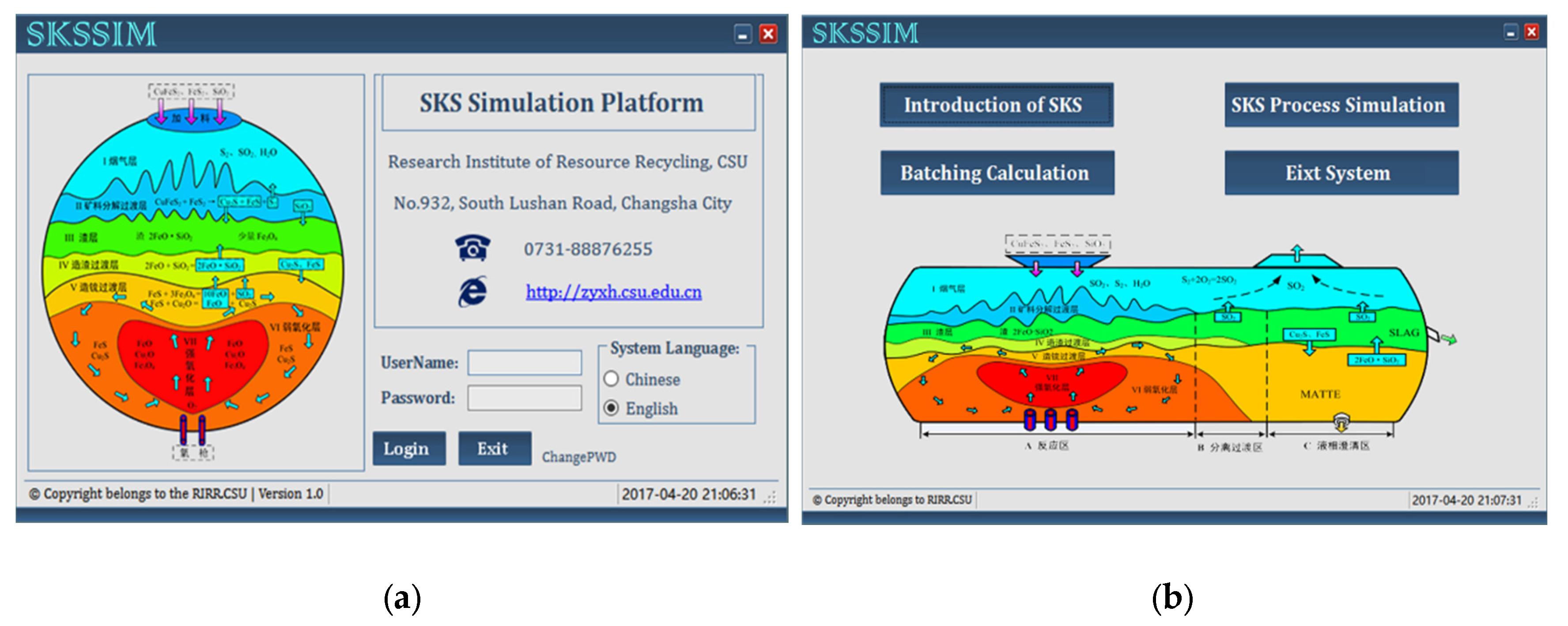
2.2. Research Methodology

The study on distribution of arsenic was carried out by SKSSIM (SKS Simulation) simulation software (version 1.0, Central South University, Changsha, China), combined with actual production in Dongying Fangyuan Nonferrous Metals Co. Ltd. (Dongying, China). SKSSIM is efficient simulation software for the SKS process, which is based on the SKS smelting mechanism and theory of Gibbs free energy minimization. The particle swarm optimization algorithm, C# computer programming language, and Microsoft Visual Studio were used to develop SKSSIM software [19], and Figure 2a,b shows the login screen and navigation interface of SKSSIM. The main function of SKSSIM software is to simulate and optimize the SKS process. SKSSIM has been successfully validated by the actual production in Dongying Fangyuan Nonferrous Metals Co. Ltd. [19]. Therefore, SKSSIM is a convenient way to carry out this study.
Under stable industrial production conditions, the fractional distributions of arsenic among matte, slag, and gas phases were 6%, 12%, and 82% in Dongying Fangyuan Nonferrous Metals Co. Ltd.
The calculation was carried out by adjusting the charging speed of dry mixed concentrates, charging speed of flux, blown speed of pure oxygen, and volume fraction of O2 in oxygen-enriched air using SKSSIM software. The calculation results can be saved in a Microsoft Excel spreadsheet format.

3. Results

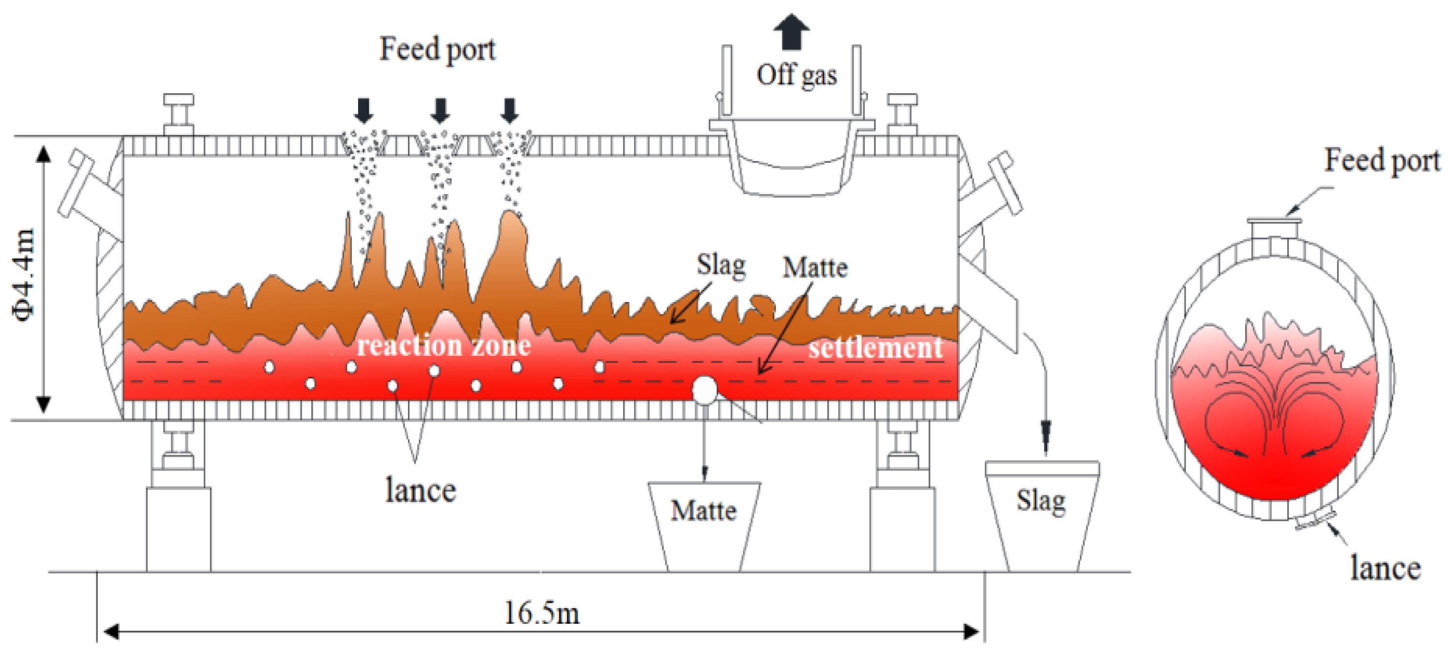
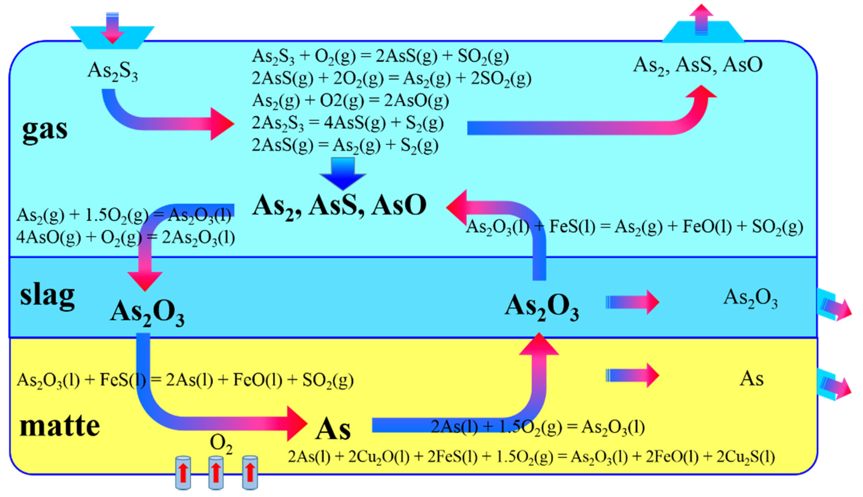
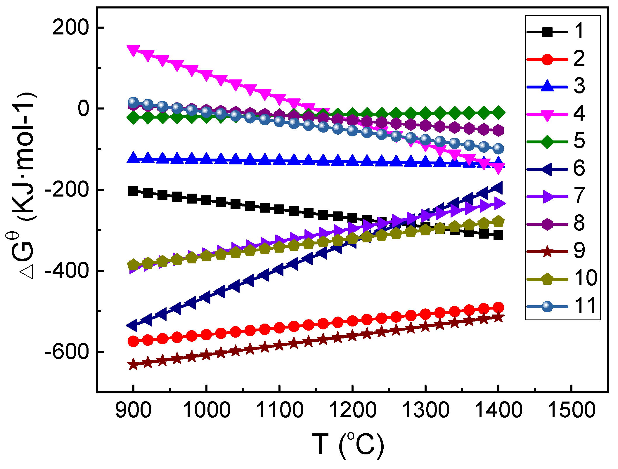
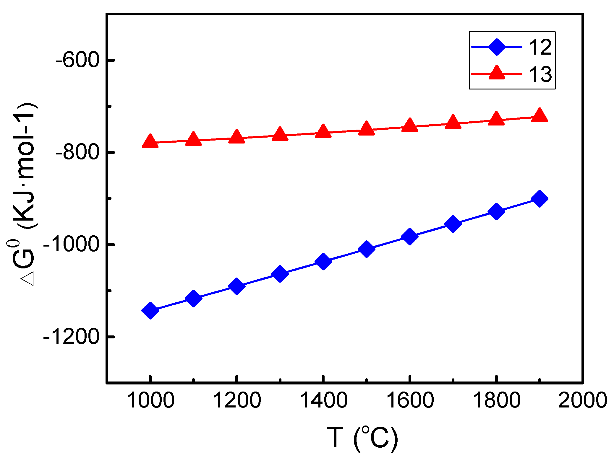
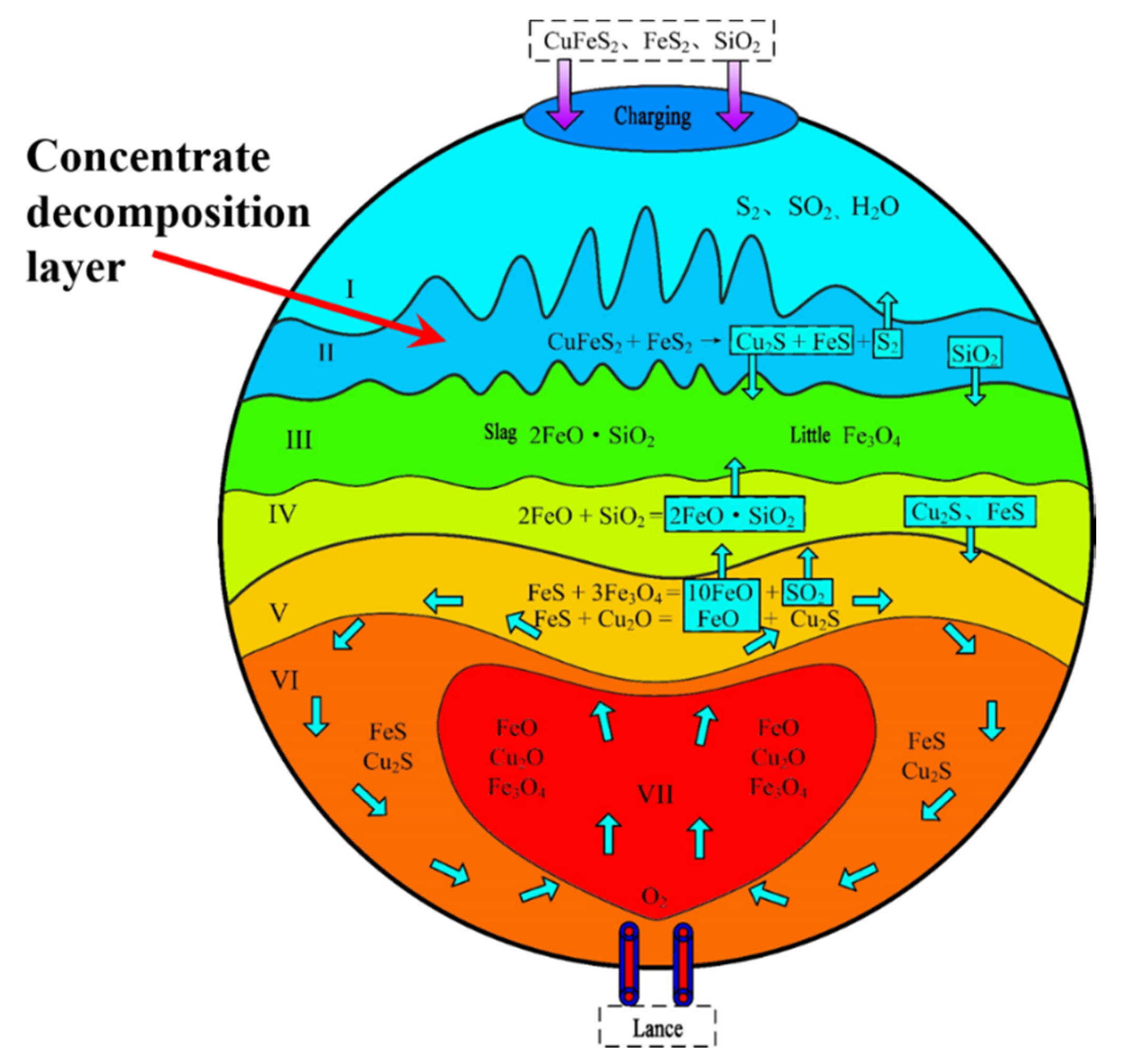
3.1. Reaction Mechanism of Arsenic in SKS Smelting Process

The oxygen bottom blown smelting system is a complicated process with many physical and chemical changes. The main probable reactions with arsenic representing bottom blown smelting system are listed as follows.
Oxidation reactions of AsxSy and As in concentrate and gas phase:
As2S3 + O2 (g) = 2AsS (g) + SO2 (g), ΔGθ = −8.5 − 0.2179T;
2AsS (g) + 2O2 (g) = As2 (g) + 2SO2 (g), ΔGθ = −725.3 + 0.0102T;
As2 (g) + O2 (g) = 2AsO (g), ΔGθ = −102.9 − 0.0237T.
Decomposing reactions of AsxSy in concentrate and gas phase:
2As2S3 = 4AsS (g) + S2 (g), ΔGθ = −664.9 − 0.5795T;
2AsS (g) = As2 (g) + S2 (g), ΔGθ = −43.3 + 0.0240T.
Arsenic transfers into slag from the gas phase in form of As2O3 (l) by oxidation reactions:
4AsO (g) + O2 (g) = 2As2O3 (l), ΔGθ = −1144.2 + 0.6789T;
As2 (g) + 1.5O2 (g) = As2O3 (l), ΔGθ = −675.1 + 0.3158T.
Arsenic transfers into matte from slag in form of As (l) by reduction of FeS (l):
As2O3 (l) + FeS (l) = 2As (l) + FeO (l) + SO2 (g), ΔGθ = −122.3 − 0.1262T.
Arsenic trasnfers into slag from matte in the form of As2O3 (l) by oxidation of Cu2O (l) and O2 (g):
2As (l) + 2Cu2O (l) + 2FeS (l) + 1.5O2 (g) = As2O3 (l) + 2FeO (l) + 2Cu2S (l), ΔGθ = −842.2 + 0.2346T;
2As (l) + 1.5O2 (g) = As2O3 (l), ΔGθ = −578.4 + 0.2143T.
Arsenic transfers into the gas phase from slag in the form of As2 (g) by reduction of FeS (l):
As2O3 (l) + FeS (l) = As2 (g) + FeO (l) + SO2 (g), ΔGθ = 219.1 − 0.2277T.
The Gibbs free energy (ΔGθ) of Reactions (1)–(11) at varying temperatures was calculated by HSC software (Outotec, Espoo, Finland) [20] and given in Figure 3. These reactions may occur spontaneously when the temperature is maintained above 1200 °C (1473 K).
Figure 4 shows the reaction mechanism and mass transfer behavior of arsenic in the SKS process. The main arsenic species in the gas phase are AsS (g), AsO (g), and As2 (g). Arsenic exists in slag predominantly as As2O3 (l), and in matte as As (l). However, a small amount of matte is mechanically entrained in slag, and vice versa. In Figure 4, the copper sulphide concentrates containing arsenic are fed into the furnace from the top feed port. As2S3 decomposes into AsS (g), S2 (g), and As2 (g), and partially are oxidized into AsO (g) under low oxygen potential. Arsenic transfers into slag from the gas phase in form of As2O3 (l) by oxidation of O2 (g), and then goes into matte from slag as As (l) by the reduction of FeS (l). As (l) in matte layer is oxidized into As2O3 (l) by Cu2O (l) and O2 (g), and returns to the slag layer. Finally, arsenic returns to the gas layer from slag layer as As2 (g) by reduction of the FeS (l) that may come from matte or concentrates.

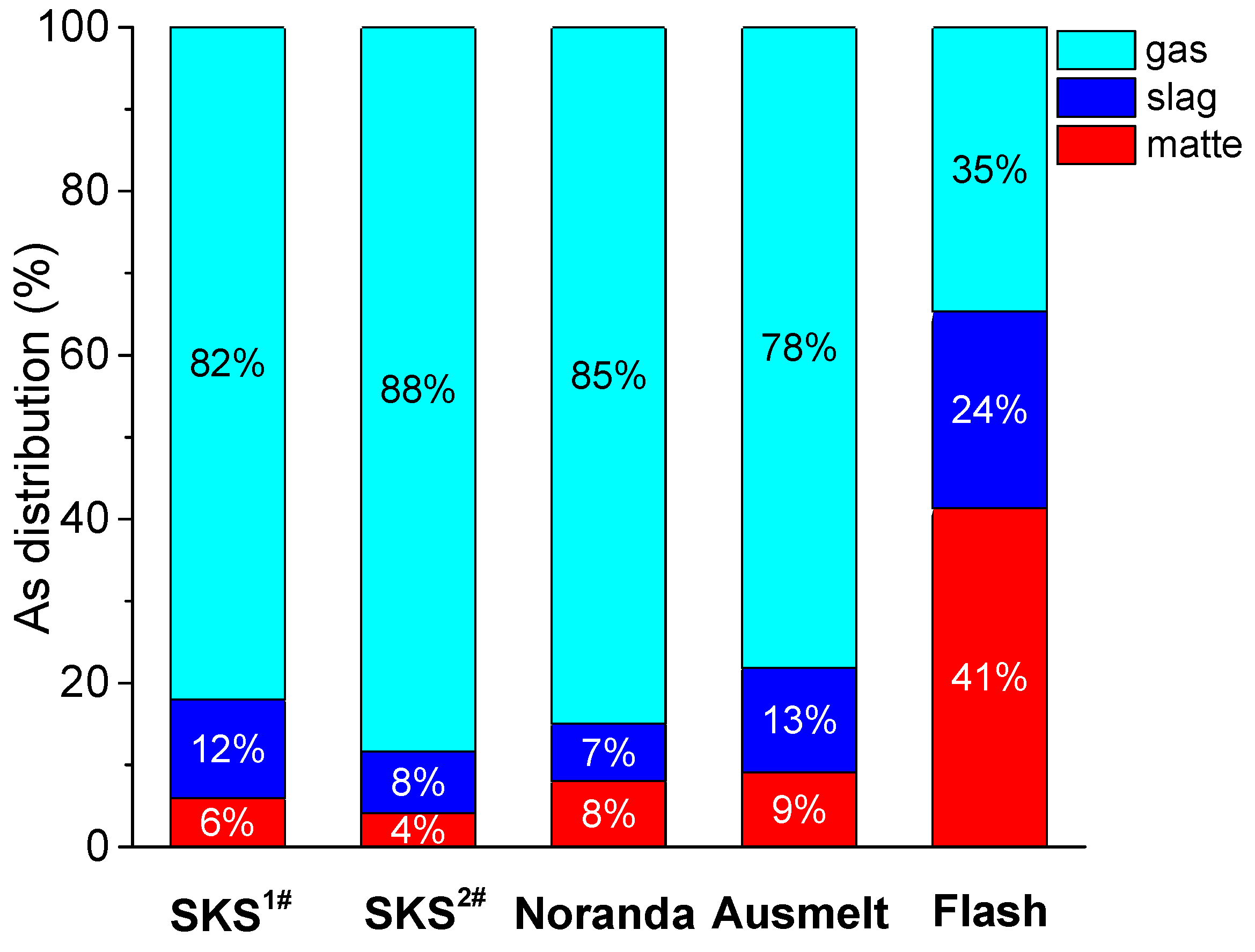
3.2. Arsenic Distribution Behavior in SKS Process and Other Processes

Figure 5 presents the comparison of arsenic distribution among matte, slag, and gas phases respectively in SKS, Noranda [13], Ausmelt [13], and Flash [13] smelting processes. The fractional distribution of arsenic reporting into gas phase in SKS, Noranda, and Ausmelt bath smelting processes is 78–88%, which is much higher than that in the Flash smelting process (35%). However, the distributions into matte and slag in above mentioned three bath smelting processes are 4–9% and 8–13%, which are much lower than that in the Flash smelting process (41% in matte and 24% in slag). It could be concluded that the bath process has much higher arsenic removal efficiency into gas phase from smelting system than the flash smelting process. Especially, in SKS process of Yantai Hengbang Smelter, 88% arsenic distributes in gas phase, and only 4% arsenic distributes in matte [13]. On the contrary, the flash smelting slag could capture much more arsenic than the SKS smelting slag.
The difference of arsenic distribution in the SKS and flash processes may be explained by the following reasons:

3.2.1. Difference of Oxygen Potential and Volatilization

In the SKS process, oxygen-enriched air is constantly blown into matte layer from the bottom of the furnace through the lance, as shown in Figure 6a. The oxygen and liquid (matte and slag) contact sufficiently, which strengthens the reacting efficiency in the smelter. Most oxygen reacts with Cu2S and FeS in the matte layer, rather than contacts with AsxSy directly. Therefore, only small part of oxygen passes through matte and slag layers into gas layer, and the oxygen potential is weak in the gas layer. Tiny arsenic is oxidized into As2O3, and most arsenic exists in form of As, AsS, and AsO. Because the vapor pressures of As, AsS, and AsO are higher than As2O3 at high temperatures (around 1200 °C) in the copper smelting system [5,7,8], most arsenic is volatilized into the gas phase in form of As2 (g), AsS (g), and AsO (g), and a small amount of the arsenic carries into the slag and matte. However, in the flash smelting process, oxygen-enriched air, concentrate particles, and fluxes enter through a single burner in the reaction shaft, and most oxidation takes place while the particles fall toward the settler, as shown in Figure 6b. The concentrate particles and oxygen-enriched air contact sufficiently, and the oxygen potential in reaction shaft is strong enough to oxidize AsxSy into As2O3. As2O3 has lower vapor pressure than AsxSy, and is more easily absorbed by slag. For the above reasons, less arsenic is present in the gas phase and more in the slag and matte phases in the flash smelting process than in the SKS process.

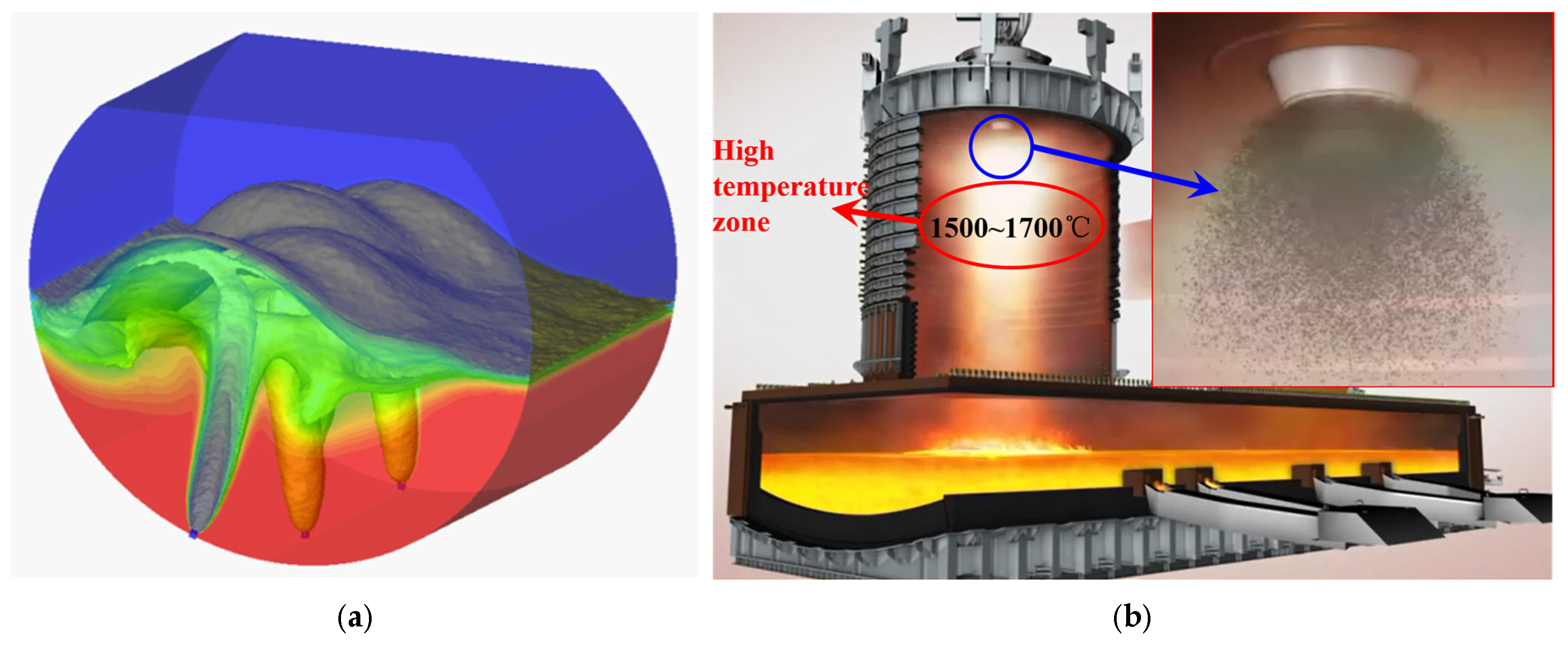
3.2.2. Difference of Smelting Temperature and Reaction Intensity

The average smelting temperature of Flash process is much higher than that of SKS process. Especially under the central nozzle in reaction shaft of Flash smelting furnace, there is a high temperature zone (1500–1700 °C) [21,22]. The oxidation reactions carry out intensely when the concentrates fall through this zone. As2S3 could be oxidized to As (l) and As2O3 (l) by O2 (g) quickly, just as the Reactions (12) and (13). The Gibbs free energy (ΔGθ) of Reactions (12) and (13) at varying temperatures was given in Figure 7. As (l) and As2O3 (l) are absorbed by matte and slag separately. However, the average smelting temperature of SKS process is around 1200 °C [19,23], and temperature above the slag layer may be lower. Therefore, the decomposition and oxidation reactions of As2S3 carry out more gently, and most As2S3 decomposes into AsS (g) or As2 (g) which are presented in the gas phase.
As2S3 + 4.5O2 (g) = As2O3 (l) + 3SO2 (g), ΔGθ = −1413.8 + 0.2697T;
As2S3 + 3O2 (g) = 2As (l) + 3SO2 (g), ΔGθ = −844.4 + 0.0629T.

3.2.3. Difference of Mass Transfer Process of Arsenic

SKS process is a typical bath smelting process. In the SKS smelting furnace, gas, slag, and matte phases coexist. The mass transfer process of arsenic should pass through the interfaces among gas, slag, and matte phases. Furthermore, the mixed concentrates are directly added into the furnace from the top feed port, and a concentrate decomposition layer is formed above the slag layer [20], as shown in Figure 8. The concentrate decomposition layer could be described as a ‘roasting layer’. AsxSy in concentrate is roasted at a high temperature, and decomposes into AsS (g), As2 (g), and S2 (g) which report into gas phase and directly exit from the SKS furnace. In actual production, once arsenic has been distributed into the gas phase, it directly goes into an exhaust-heat boiler and returns to slag and matte. However, in the flash smelting process, AsxOy (gas or liquid) and slag and matte droplets contact sufficiently in the reaction shaft, and arsenic could be absorbed by slag and matte directly. Thus, the content of arsenic in slag and matte is higher.

3.3. Effects of Operation Parameters on Arsenic Distribution Behavior

The distribution of arsenic in different smelting processes is dependent on multiple contributing factors, such as raw material compositions, thermodynamic properties, process characteristics, and operation parameters. For different processes, the operation parameters are diverse and have significant effects on arsenic distribution behavior. In the SKS process, the compositions of the mixed concentrates into the furnace are listed in Table 1, and the operation parameters are listed in Table 2. It is necessary to discuss the effects of main operation parameters on arsenic distribution.

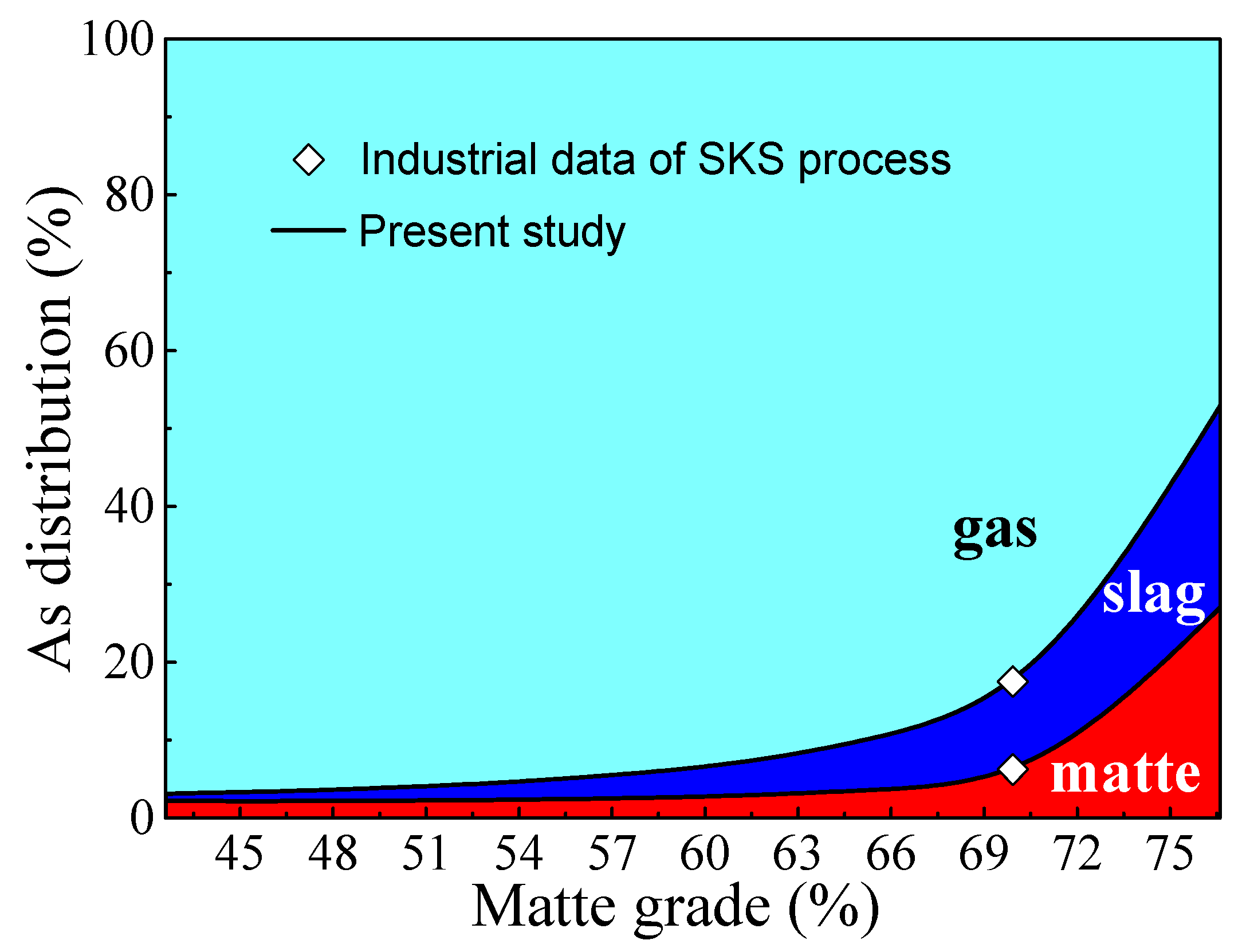
3.3.1 Effects of Matte Grade

Matte grade is a key production parameter, and many factors could affect this parameter. In present work, by adjusting the blown speed of pure oxygen and air in Table 2, the blown speed of total oxygen could change from 6067 Nm3/h to 12,807 Nm3/h, and the volume fraction of O2 in oxygen-enriched air was fixed at 73%. Finally, the smelting result would be that matte grade changes from 42.57% to 76.36%. In the calculation, the composition of the mixed concentrates into the furnace was fixed.
In Figure 9, the variations in the calculated distribution of arsenic among the gas, slag, and matte phases with the final matte grade in SKS process are present. Under stable industrial production conditions of SKS process, more than 80% of arsenic is present in the gas. Its distribution among slag and matte is around 12% and 6% respectively. Concentrating the arsenic to the gas phase is a feature of the SKS smelting process. Figure 9 also shows that at low matte grades (such as 60%), where more than 90% of the arsenic is present in the gas phase with the balance being slightly contained in the matte. However, with the increase of the matte grades, the proportion of arsenic reporting to the matte phase also increases. When the matte grade rises up to 77%, around 30% of the arsenic transfers to matte. The phenomenon may be explained by the following reasons: the activity coefficient of As in matte decreases with an increasing matte grade, and higher grade matte has a higher affinity for arsenic and hence reduces the activity and vapor pressure of arsenic [7,18]. The activity of sulfur in mattes also decreases with increasing matte grade, causing lower partial pressures of S2 and a lower degree of volatilization of arsenic as AsS at higher matte grades [7,18]. So high matte grade is not helpful in removing arsenic. Dealing with complex copper concentrates of high arsenic content by SKS smelting process, the matte grade should be reduced appropriately.

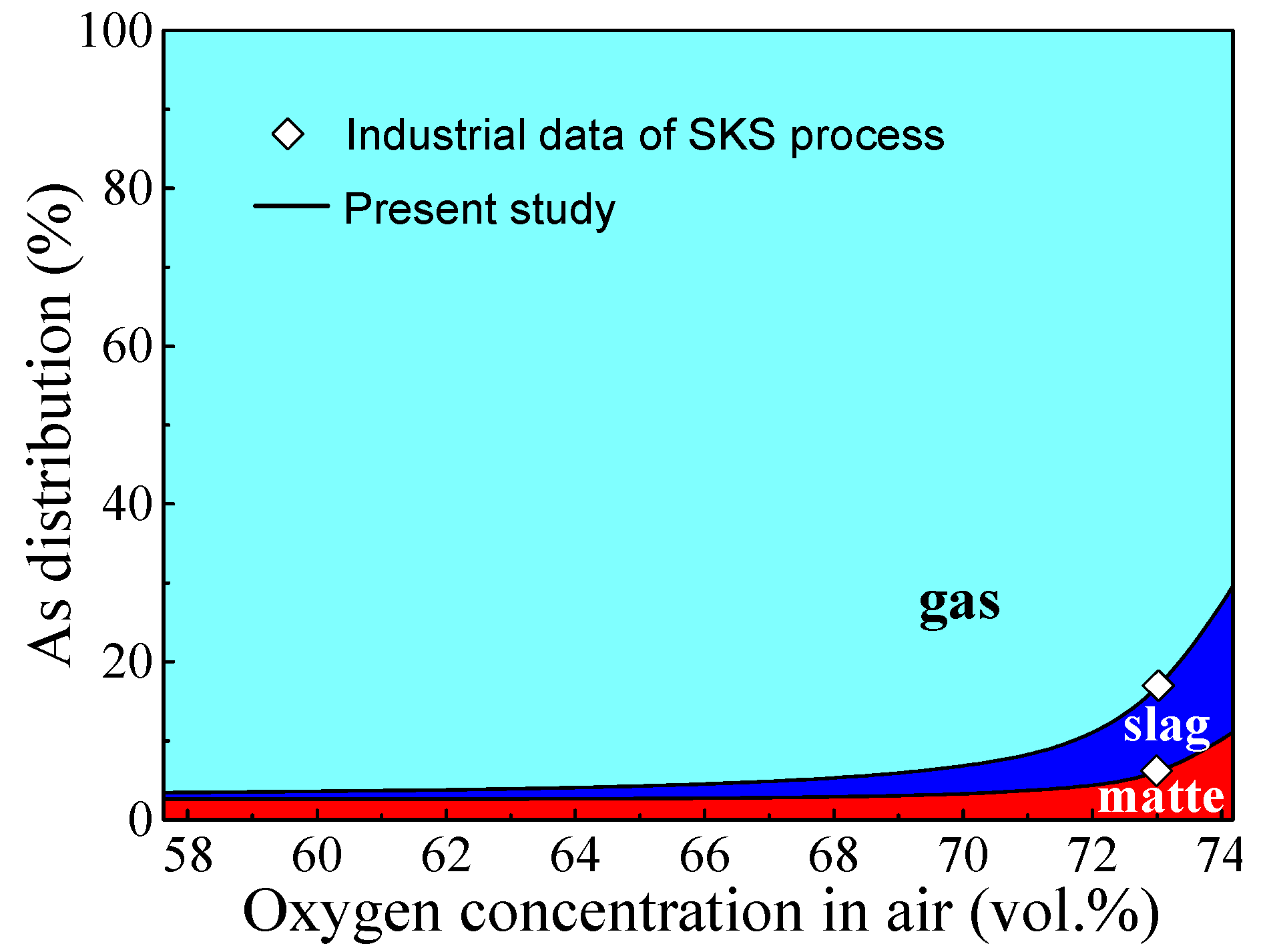
3.3.2 Effects of Oxygen Concentrations in Air

Volume concentration of O2 in oxygen-enriched air is a significant parameter for any smelting process, and it would remarkably affect the distributions of minor elements, especially volatile elements, such as arsenic. In the present study, by adjusting the blown speed of pure oxygen from 4885 Nm3/h to 11,610 Nm3/h and fixing the blown speed of air in Table 2, the volume fraction of O2 in oxygen-enriched air could change from 57.63% to 74.14%. In the calculation, the composition of the mixed concentrates into the furnace and other operation parameters were fixed.
In Figure 10, as the O2 concentration in air increases, the proportions of arsenic present in matte and slag phases both increase, and gas phase decreases. As volume concentration of O2 in air >72%, the distribution of arsenic in gas phase decreases sharply with an increasing concentration of O2. The apparent effect is caused by the changing of total air volume. In practice, the SKS furnace is an open system, i.e., gas is passing through the furnace, which would increase the amount of volatile species leaving the furnace [8]. In this calculation, the charging speed of total oxygen is fixed at 12,072 Nm3/h, the total air volume blown into SKS furnace decreases with an increasing concentration of O2, and the removal efficiency of arsenic also decreases by gas phase. The other key factor to consider is the increase of oxygen potential as the concentration of O2 in air increases. AsxSy is more easily oxidized to As2O3 (l) and As (l) at high oxygen potential, which are absorbed by slag and matte separately.

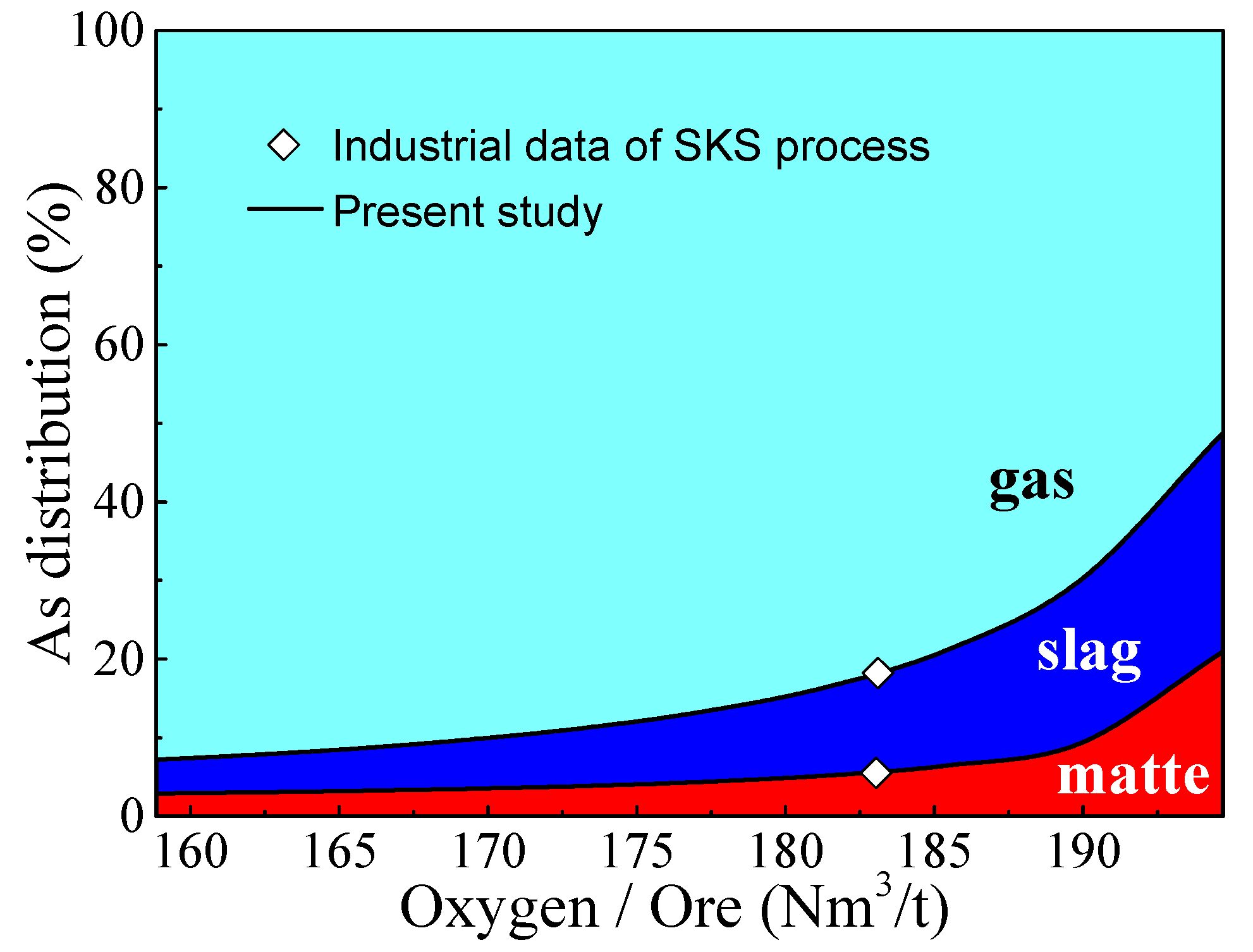
3.3.3 Effects of the Oxygen/Ore Ratio

The ratio of oxygen/ore (total volume of oxygen/total mass of dry mixed concentrates) is also a key production parameter. In the present study, by adjusting the charging speed of dry mixed concentrates from 62 t/h to 76 t/h and fixing the blown speed of pure oxygen and air in Table 2, the ratio of oxygen/ore changed from 158.8 Nm3/t to 194.7 Nm3/t finally. In the calculation, the composition of the mixed concentrates into the furnace and other operation parameters were also fixed.
Figure 11 shows the calculated effect of the ratio of oxygen/ore on the distribution of As among the gas, slag, and matte phases in SKS process. As the ratio of oxygen/ore increases, the proportions of arsenic reporting to matte and slag phases both increase, and the gas phase decreases. The variation trend is similar to the effect of matte grade, resulting from the linear relationship between the ratio of oxygen/ore and matte grade. As the ratio of oxygen/ore increases, matte grade also increases with fixed raw material compositions.

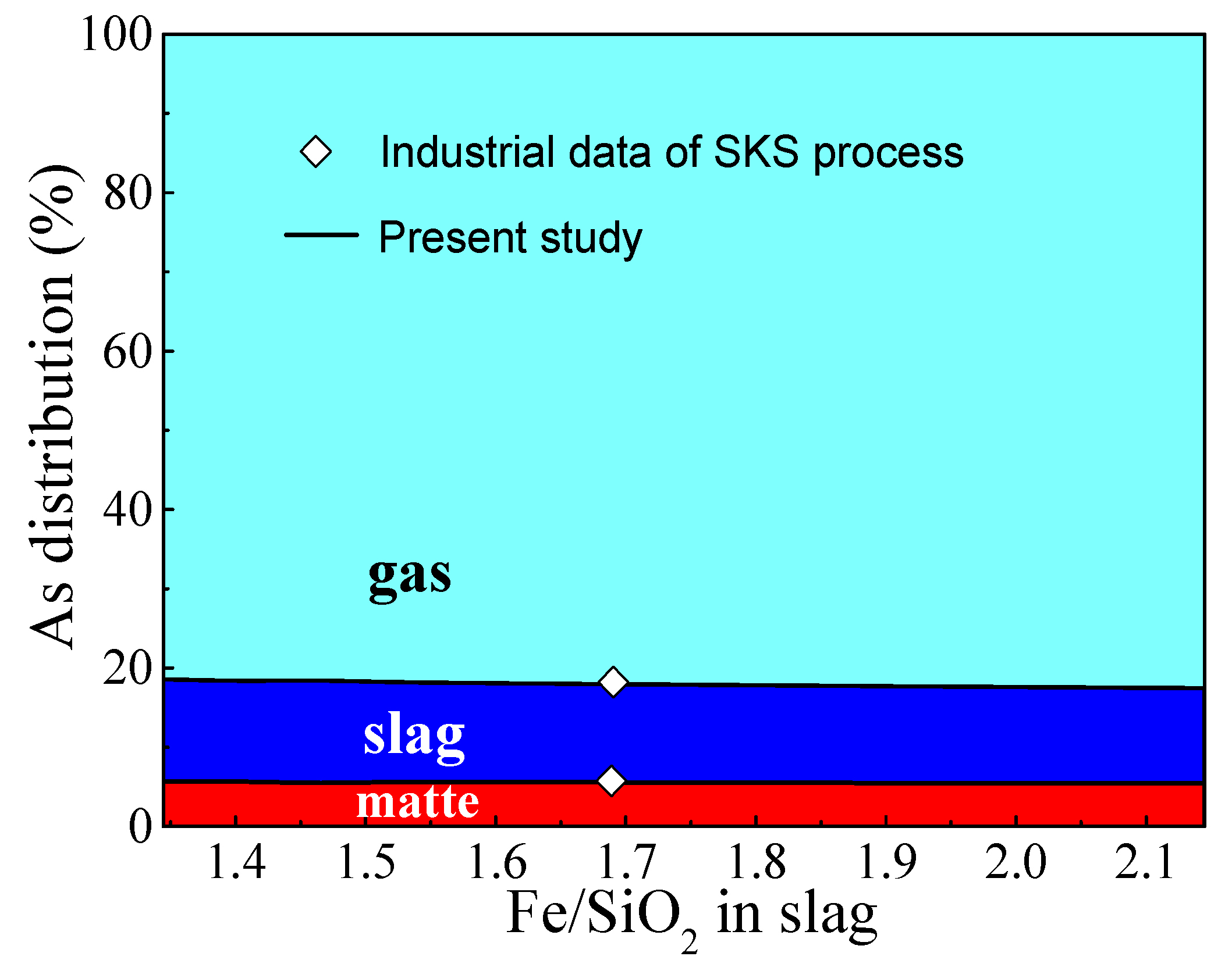
3.3.4. Effects of the Ratio of Fe/SiO2 in Slag

The ratio of Fe/SiO2 in slag could remarkably affect copper loss to slag, and it might also affect the distribution of arsenic. In the present study, by adjusting the charging speed of flux (SiO2) from 3.5 t/h to 9.0 t/h and fixing the charging speed of dry mixed concentrates at 66 t/h in Table 2, the smelting result is that the ratio of Fe/SiO2 in slag changes from 1.33 to 2.17. In the calculation, the composition of the mixed concentrates into the furnace and other operation parameters were also fixed.
Figure 12 shows the distributions of arsenic among gas, slag, and matte phases with various ratios of Fe/SiO2 (1.33–2.17). As is shown, the changing of ratio of Fe/SiO2 has slight effects on the distributions of arsenic. Therefore, in practice, the ratio of Fe/SiO2 is not the key influence factor to control the removal of As to the gas phase in SKS process.

4. Conclusions

Under stable production conditions, the fractional distributions of arsenic among matte, slag, and gas phases are 6%, 12%, and 82%, respectively. The main arsenic species in gas phase are AsS (g), AsO (g), and As2 (g). Arsenic exists in slag predominantly as As2O3 (l), and in matte as As (l). There are obvious differences of arsenic distribution in the SKS and Flash processes, and this phenomenon may be explained by the differences of oxygen potential, volatilization, smelting temperature, reaction intensity, and mass transfer process. In the SKS smelting process, as oxygen concentration, ratios of oxygen/ore and matte grade increase individually, the relative portions of arsenic that report to the gas phase all decrease, and the fractional distributions in slag and matte increase. High matte grade is harmful to the elimination of arsenic. The changing of Fe/SiO2 has slight effects on the distributions of arsenic. It could be concluded that in order to enhance the removal of arsenic from the SKS smelting system in the gas phase, low oxygen concentration, low ratios of oxygen/ore, and low matte grade should be chosen. In the SKS smelting process, no dust is recycled, and almost all dust is collected and further treated to eliminate arsenic and recover valuable metals by other process streams. Therefore, the SKS smelting process is an efficient way to treat arsenic-bearing concentrates.

Acknowledgments

The authors would like to acknowledge the National Nature Science Foundation of China (No. 51620105013) for financial support, and Dongying Fangyuan Nonferrous Metals Co., Ltd. for providing the industrial production data.

Author Contributions

Xueyi Guo and Baojun Zhao designed the research. Qinmeng Wang carried out the research and wrote the paper. Xueyi Guo, Qinghua Tian, Mao Chen, and Baojun Zhao reviewed and contributed to the final manuscript.

Conflicts of Interest

The authors declare no conflict of interest.

References

  1. Kobayashi, Y.; Hirano, S. Distribution and excretion of arsenic metabolites after oral administration of seafood-related organoarsenicals in rats. Metals 2016, 6, 231. [Google Scholar] [CrossRef]
  2. Dosmukhamedov, N.; Kaplan, V. Efficient removal of arsenic and antimony during blast furnace smelting of lead-containing materials. JOM 2017, 69, 381–387. [Google Scholar] [CrossRef]
  3. Zhong, D.P.; Li, L.; Tan, C. Separation of arsenic from the antimony-bearing dust through selective oxidation using CuO. Metall. Mater. Trans. B 2017, 48, 1308–1314. [Google Scholar] [CrossRef]
  4. Yang, W.C.; Tian, S.Q.; Wu, J.X.; Chai, L.Y.; Liao, Q. Distribution and behavior of arsenic during the reducing-matting smelting process. JOM 2017. [Google Scholar] [CrossRef]
  5. Yazawa, A.; Azakami, T. Thermodynamics of removing impurities during copper smelting. Can. Metall. Q. 1969, 8, 257–261. [Google Scholar] [CrossRef]
  6. Nakazawa, S.; Yazawa, A.; Jorgensen, F.R.A. Simulation of the removal of arsenic during the roasting of copper concentrate. Metall. Mater. Trans. B 1999, 30, 393–401. [Google Scholar] [CrossRef]
  7. Chen, C.L.; Zhang, L.; Jahanshahi, S. Thermodynamic modeling of arsenic in copper smelting process. Metall. Mater. Trans. B 2010, 41, 1175–1185. [Google Scholar] [CrossRef]
  8. Swinbourne, D.R.; Kho, T.S. Computational thermodynamics modeling of minor element distributions during copper flash converting. Metall. Mater. Trans. B 2012, 43, 823–829. [Google Scholar] [CrossRef]
  9. Coursol, P.; Mackey, P.J.; Kapusta, J.P.T.; Valencia, N.C. Energy consumption in copper smelting: A new Asian horse in the race. JOM 2015, 67, 1066–1074. [Google Scholar] [CrossRef]
  10. Li, W.F.; Zhan, J.; Fan, Y.Q.; Wei, C.; Zhang, C.F.; Hwang, J.Y. Research and industrial application of a process for direct reduction of molten high-lead smelting slag. JOM 2017, 69, 784–789. [Google Scholar] [CrossRef]
  11. Chen, L.; Hao, Z.D.; Yang, T.Z.; Liu, W.F.; Zhang, D.C.; Zhang, L.; Bin, S.; Bin, W.D. A comparison study of the oxygen-rich side blow furnace and the oxygen-rich bottom blow furnace for liquid high lead slag reduction. JOM 2015, 67, 1123–1129. [Google Scholar] [CrossRef]
  12. Liu, W.F.; Yang, T.Z.; Zhang, D.C.; Chen, L.; Liu, Y.F. A new pyrometallurgical process for producing antimony white from by-product of lead smelting. JOM 2014, 66, 1694–1700. [Google Scholar] [CrossRef]
  13. Qu, S.L.; Dong, Z.Q.; Chen, T. Distribution of minor elements in complex copper concentrates in oxygen-enriched bottom blown smelting process. China Nonferrous Metall. 2016, 3, 22–24. (In Chinese) [Google Scholar]
  14. Shui, L.; Cui, Z.X.; Ma, X.D.; Rhamdhani, M.A.; Nguyen, A.V.; Zhao, B.J. Mixing phenomena in a bottom blown copper smelter: A water model study. Metall. Mater. Trans. B 2015, 46, 1218–1225. [Google Scholar] [CrossRef]
  15. Shui, L.; Cui, Z.X.; Ma, X.D.; Rhamdhani, M.A.; Nguyen, A.V.; Zhao, B.J. Understanding of bath surface wave in bottom blown copper smelting furnace. Metall. Mater. Trans. B 2016, 47, 135–144. [Google Scholar] [CrossRef]
  16. Zhang, Z.Y.; Chen, Z.; Yan, H.J.; Liu, F.K.; Liu, L.; Cui, Z.X.; Shen, D.B. Numerical simulation of gas-liquid multi-phase flows in oxygen enriched bottom-blown furnace. Chin. J. Nonferrous Met. 2012, 22, 1826–1834. (In Chinese) [Google Scholar]
  17. Yan, H.J.; Liu, F.K.; Zhang, Z.Y.; Gao, Q.; Liu, L.; Cui, Z.X.; Shen, D.B. Influence of lance arrangement on bottom-blowing bath smelting process. Chin. J. Nonferrous Met. 2012, 22, 2393–2400. (In Chinese) [Google Scholar]
  18. Chen, C.L.; Jahanshahi, S. Thermodynamics of arsenic in FeOX-CaO-SiO2 slags. Metall. Mater. Trans. B 2010, 41, 1166–1174. [Google Scholar] [CrossRef]
  19. Liao, L.L.; Wang, Q.M.; Tian, Q.H.; Guo, X.Y. Multiphase equilibrium modeling study on the oxygen bottom blowing copper smelting (SKS) process. In Proceedings of the 9th International Copper Conference (Copper 2016), Kobe, Japan, 13–16 November 2016; pp. 1252–1264. [Google Scholar]
  20. HSC Chemistry, version 6.1. Chemical Reaction and Equilibrium Software with Extensive Thermochemical Database. Outokumpu: Pori, Finland, 2007.
  21. Li, X.F. The numerical analysis and optimization on process in copper flash furnace. Ph.D. Thesis, Central South University, Changsha, China, October 2001. (In Chinese). [Google Scholar]
  22. Li, J.B. Multifield Simulation of Copper Flash Smelting Process Based on Fluent Software. Master’s Thesis, JiangXi University of Science and Technology, Ganzhou, China, June 2001. (In Chinese). [Google Scholar]
  23. Wang, Q.M.; Guo, X.Y.; Tian, Q.H. Copper smelting mechanism in oxygen bottom-blown furnace. Trans. Nonferrous Met. Soc. China 2017, 27, 946–953. [Google Scholar] [CrossRef]
Figure 1. Schematic diagram of SKS (Shuikoushan) process.
Metals 07 00302 g001
Figure 2. Login screen and navigation interface of SKSSIM: (a) login screen; (b) navigation interface.
Metals 07 00302 g002
Figure 3. Relationships between ΔGθ (kJ·mol−1) and temperature (°C) of Reactions (1)–(11).
Metals 07 00302 g003
Figure 4. Reaction mechanism and mass transfer behavior of arsenic in the SKS process.
Metals 07 00302 g004
Figure 5. Distribution of arsenic in different smelting processes. SKS1#: industrial data of SKS process with matte grade 70% in Dongying Fangyuan Smelter; SKS2#: industrial data of SKS process with matte grade 50% in Yantai Hengbang Smelter.
Metals 07 00302 g005
Figure 6. Schematic diagram of multiphase interaction in different processes; (a) SKS process; (b) Flash process.
Metals 07 00302 g006
Figure 7. Relationships between ΔGθ (kJ·mol−1) and temperature (°C) in Reactions (12) and (13).
Metals 07 00302 g007
Figure 8. Mechanism model of SKS process in reaction zone.
Metals 07 00302 g008
Figure 9. Effects of matte grade on arsenic distribution in SKS process.
Metals 07 00302 g009
Figure 10. Effects of oxygen concentrations on arsenic distribution in SKS process.
Metals 07 00302 g010
Figure 11. Effects of the ratio of oxygen/ore on arsenic distribution in SKS process.
Metals 07 00302 g011
Figure 12. Effects of the ratio of Fe/SiO2 in slag on arsenic distribution.
Metals 07 00302 g012
Table 1. Compositions of the mixed concentrates into the furnace.
CompositionsCuFeSPbZnAsSbBiSiO2MgOCaOAl2O3Others
Content (wt %)24.426.828.60.961.90.370.100.106.41.92.42.33.9
Table 2. Industrial operation parameters in SKS (Shuikoushan) process.
Operation ParametersSKS Plant Data
Charging speed of dry mixed concentrates (t/h)66
Water percent in the mixed concentrates (%)10.21
Charging speed of flux (t/h)5.277
Smelting temperature (K)1473
Negative pressure in furnace (Pa)50–200
Volume of pure oxygen (Nm3/h)10,885
Volume of air (Nm3/h)5651
Volume of O2 in oxygen-enriched air (%)73
Matte grade (%)70
Oxygen efficiency (%)99

