Article

Effect of Welding Heat Input on Microstructure and Low-Temperature Toughness of Laser-Arc Hybrid Welded Super-Duplex Stainless-Steel Joints


1
College of Aviation and Materials, Anhui Technical College of Mechanical and Electrical Engineering, Wuhu 241000, China
2
Wuhu Engineering Technology Research Center for Intelligent Welding Robots, Wuhu 241000, China
3
School of Materials Science and Engineering, Shanghai Jiao Tong University, Shanghai 200240, China
*
Author to whom correspondence should be addressed.
Metals 2026, 16(7), 787; https://doi.org/10.3390/met16070787
Submission received: 15 June 2026 / Revised: 9 July 2026 / Accepted: 10 July 2026 / Published: 13 July 2026
(This article belongs to the Special Issue Laser Welding of Steels and Alloys)

Abstract

This paper studies the effect of welding heat input on microstructure and low-temperature toughness of laser-arc hybrid welded (LAHW) SAF2507 super-duplex stainless-steel (SDSS) joints. Heat input was adjusted from 0.204 to 0.407 kJ/mm by changing the welding speed. Results indicate that low heat input brings high ferrite content and low impact toughness. The medium heat input generates a balanced two-phase microstructure and gains the highest impact energy of 36.0 J at −46 °C. Excessively high heat input results in obvious grain coarsening and degraded impact performance. This study offers an experimental basis and parameter reference for practical welding production.

1. Introduction

SDSS is widely employed in demanding offshore, chemical, and petrochemical applications due to its exceptional combination of high strength, excellent corrosion resistance, and good toughness [1,2,3,4,5]. Its use in critical environments like deep-sea pipelines and Arctic structures, where components are exposed to sub-zero temperatures and cathodic protection, places paramount importance on the low-temperature toughness of welded joints. Historically, inadequate toughness in such conditions has been linked to catastrophic failures, such as hydrogen-induced stress cracking in subsea assets [6]. Welding, however, poses a significant metallurgical challenge to this key property. The primary issue is maintaining a balanced ferrite/austenite phase ratio near 50/50 in the weld zone, as deviations and microstructural changes severely degrade performance.
Extensive research on welding SDSS reveals common challenges across different processes. Studies on advanced techniques like Cold-Metal Transfer-Pulse welding have shown that the heat-affected zone (HAZ) often becomes a weak toughness link, exhibiting the lowest austenite content (as low as 32.3%) and susceptibility to detrimental Cr2N nitride precipitation [7]. While methods such as adding nitrogen to the shielding gas can improve austenite reformation and toughness, the fundamental sensitivity of the HAZ to thermal cycles remains. Similarly, investigations into traditional methods like shielded metal arc welding have focused on fracture toughness at temperatures as low as −40 °C [8,9]. However, the faster thermal cycles introduced by modern, high-productivity welding processes necessitate a renewed evaluation of their impact on microstructural stability and, crucially, low-temperature impact toughness [10]. The common threat across all arc welding processes is the potential for welding thermal cycles to promote an unbalanced microstructure, grain coarsening, and the precipitation of brittle intermetallic phases (e.g., sigma phase), collectively compromising the ductility of the ferrite phase at low temperatures and making the weld joint a reliability concern [11].
To address these limitations, LAHW has emerged as a promising advanced joining technology. It synergistically combines the deep penetration and high speed of laser welding with the superior gap-bridging ability and process stability of arc welding [12,13]. For SDSS, LAHW offers the potential for higher welding speeds, lower overall heat input, and more precise thermal control. This leads to narrower HAZs, reduced distortion, and, most importantly, tighter regulation of the cooling rate—a key factor controlling phase transformation kinetics and the suppression of harmful precipitates. Consequently, LAHW presents a distinct opportunity to produce welded joints with a more favorable and stable microstructure, which is a prerequisite for achieving excellent mechanical properties, including low-temperature toughness [14,15].
Initial research on laser welding and LAHW of duplex stainless steels has demonstrated advantages in productivity and joint integrity [16,17]. However, a critical and systematic investigation focusing on the low-temperature toughness of SDSS LAHW joints is notably absent from the literature. Existing studies often prioritize macro-characteristics, hardness, or corrosion resistance, leaving a significant gap in understanding the microstructure–toughness relationship under controlled thermal conditions. Most published works only evaluate mechanical performance at room temperature or limited single heat input conditions, while few systematically track the continuous evolution of dual-phase microstructure and cryogenic impact performance under a full gradient of heat inputs. Specifically, the role of welding heat input—a master variable directly manipulated via welding speed in industrial practice—on the phase balance and consequent impact energy at service-relevant low temperatures (e.g., −46 °C) remains poorly elucidated. Few existing reports further distinguish the toughness difference and failure mechanism between the weld metal and HAZ under identical heat input gradients, ignoring that the HAZ acts as the intrinsic thermally controlled weak region unable to be adjusted by filler wire. This knowledge gap hinders the development of optimized, reliability-focused welding procedures.
Therefore, this study aims to bridge this gap by systematically investigating the effect of welding heat input on the microstructure and mechanical properties of LAHW joints in SAF2507 SDSS. Unlike previous limited studies, this work carries out gradient heat input experiments covering low, medium and high thermal cycles, and separately characterizes the low-temperature impact toughness of weld center and HAZ notch specimens at −46 °C. We quantitatively measure the ferrite/austenite fraction of weld metal, correlate continuous microstructural evolution with tensile and cryogenic impact performance, and further clarify the distinct fracture failure characteristics corresponding to different heat input levels. By producing joints with varying heat inputs through controlled changes in welding speed and conducting comprehensive microstructural analysis coupled with tensile and −46 °C Charpy impact tests, this work seeks to establish a clear processing–structure–property relationship. The findings are intended to provide a scientific basis for parameter selection to achieve LAHW joints in SDSS that meet the stringent demands of modern low-temperature and corrosive service environments.

2. Materials and Methods

2.1. Materials and Joint Preparation

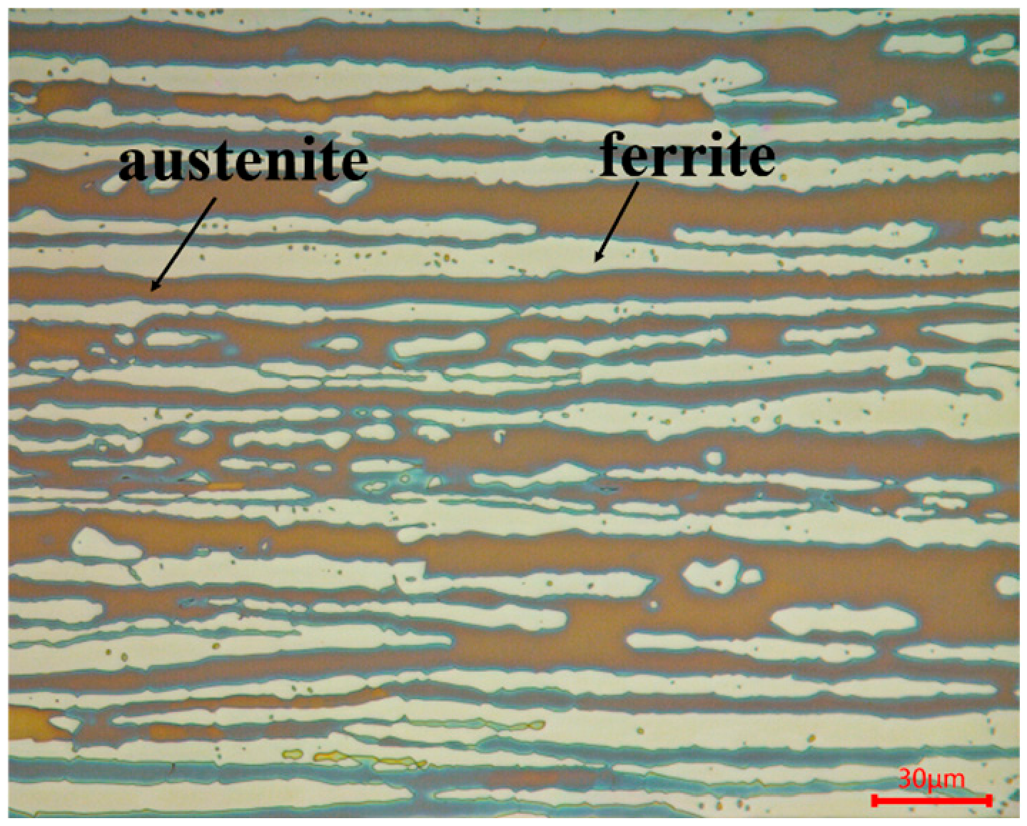
The base metal (BM) adopted in this study was a 6 mm-thick SAF2507 SDSS plate (Taiyuan Iron and Steel (Group) Co., Ltd., Taiyuan, Shanxi, China), and the matching filler wire was ER2594 (Sichuan Atlantic Welding Materials Co., Ltd., Zigong, Sichuan, China) with a diameter of 1.2 mm. The chemical compositions of the BM and filler metal are listed in Table 1 and Table 2, respectively. The as-received BM presents a typical dual-phase microstructure, where the contents of ferrite (α) and austenite (γ) are roughly equivalent, as displayed in Figure 1. Before welding, all plates were machined with an I-groove. The groove surfaces were mechanically polished to remove contaminants, guaranteeing a clean surface and uniform assembly for butt joint welding. Considering the excellent penetration capacity of laser-arc hybrid welding, the 6 mm-thick plate can be fully penetrated via a single welding pass. Thus, the simple I-groove is adopted instead of the traditional V-groove.

2.2. Welding Procedure and Heat Input Design

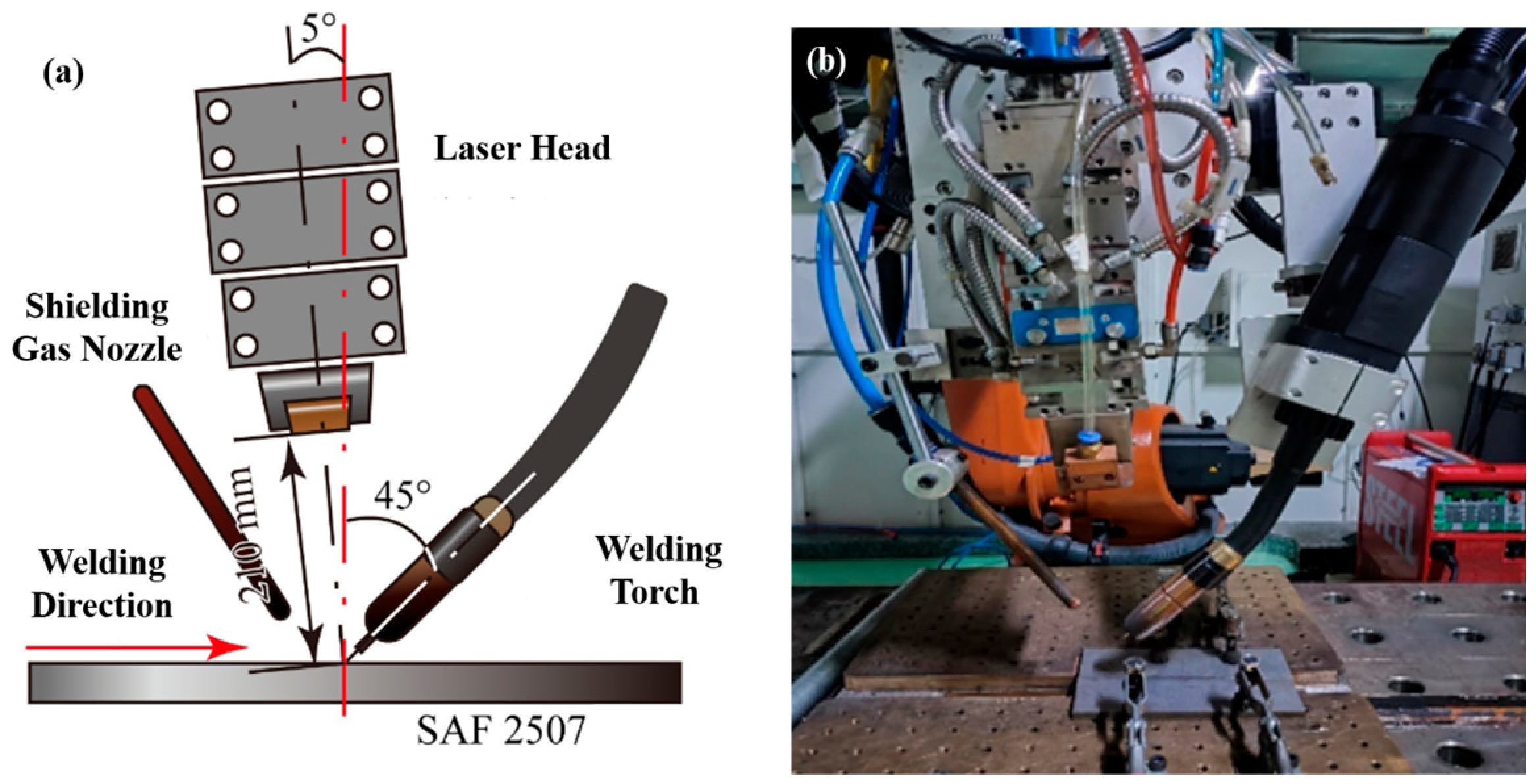
The LAHW experiments were performed using an IPG YLS-6000 fiber laser system (IPG Photonics Corporation, Marlborough, MA, USA) combined with a Fronius TPS-5000 arc welding source (Fronius International GmbH, Wels, Austria). A key feature of the setup was the self-developed hybrid welding torch, mounted on a KUKA robot, which operated in an arc-leading mode, as shown in Figure 2. The laser head was tilted at 5°, and the angle between the laser beam and the MIG torch nozzle was set at 50°. A mixed gas of argon plus 2% nitrogen was used as the front shielding gas for the MIG torch and was delivered coaxially through the welding torch at a flow rate of 25 L/min. This gas mixture can effectively inhibit nitrogen loss via diffusion on the weld surface of duplex stainless steel. Meanwhile, high-purity argon (99.99%) was used as the back shielding gas with a flow rate of 5 L/min to prevent oxidation of the weld root.
The core experimental variable was the welding heat input, which was calculated by integrating the laser power and arc thermal energy. The formula for heat input calculation of laser-arc hybrid welding is shown in Equation (1) [18]:
Q = η P l a s e r + I U 1000 v
where
Q is the heat input, unit: kJ/mm.
η is the comprehensive thermal efficiency coefficient of laser-arc hybrid welding; a value of 0.8 is adopted in this work. The range of η for fiber laser–MIG hybrid welding on stainless steel is widely reported as 0.75–0.85 in the existing literature; the selected value comprehensively accounts for the laser energy absorption efficiency of the duplex stainless-steel substrate and arc heat transfer efficiency.
Plaser is the laser power, unit: W (J/s).
I is the arc current, unit: A.
U is the arc voltage, unit: V.
v is the welding speed, unit: mm/s. Since the welding speed recorded in this experiment is measured in m/min, a unit conversion is required to convert v from m/min to mm/s, as shown in Equation (2):
v = 1000 v m i n 60 ,
where vmin denotes the original welding speed value with the unit of m/min. Substituting the conversion relation into the above formula, the final heat input calculation formula based on the raw welding speed data vmin (m/min) is obtained as Equation (3):
Q = 60 η P l a s e r + I U 1000 2 v m i n ,
To isolate its effect, a series of preliminary trial welding tests was first carried out to screen stable baseline welding parameters and establish a stable welding parameter window that ensured sound weld formation with no defects such as porosity, cracks, or incomplete penetration. Based on this optimization, the following parameters were held constant: laser power (3000 W), welding current (143 A), arc voltage (14.7 V), laser-to-wire distance (1 mm), and defocus distance (+20 mm). Welding speed was selected as the sole variable to regulate heat input, and the range of 0.6–1.2 m/min was determined from preliminary trials because fully sound, defect-free welds can be steadily obtained within this speed interval. The four gradient speeds of 0.6 m/min, 0.8 m/min, 1.0 m/min, and 1.2 m/min were systematically set, generating four distinct heat input levels ranging from 0.204 kJ/mm to 0.407 kJ/mm, corresponding to four joint specimens (labeled 1 to 4), as detailed in Table 3. This single-variable design allows for a direct assessment of how changes in the cooling rate, governed by heat input, affect the solid-state phase transformations and final microstructure.

2.3. Microstructural and Mechanical Characterization

The welded joints were cross-sectioned perpendicular to the welding direction using wire electrical discharge machining to avoid damage to the microstructure. The specimens for metallographic observation were prepared using standard procedures of mounting, grinding, polishing, and finally etching with a solution of 100 mL HCl, 100 mL C2H5OH, and 5 g CuCl2. The microstructures of the weld metal (WM) and HAZ were examined using a Leica DM2500M optical microscope (Leica Microsystems GmbH, Wetzlar, Germany).
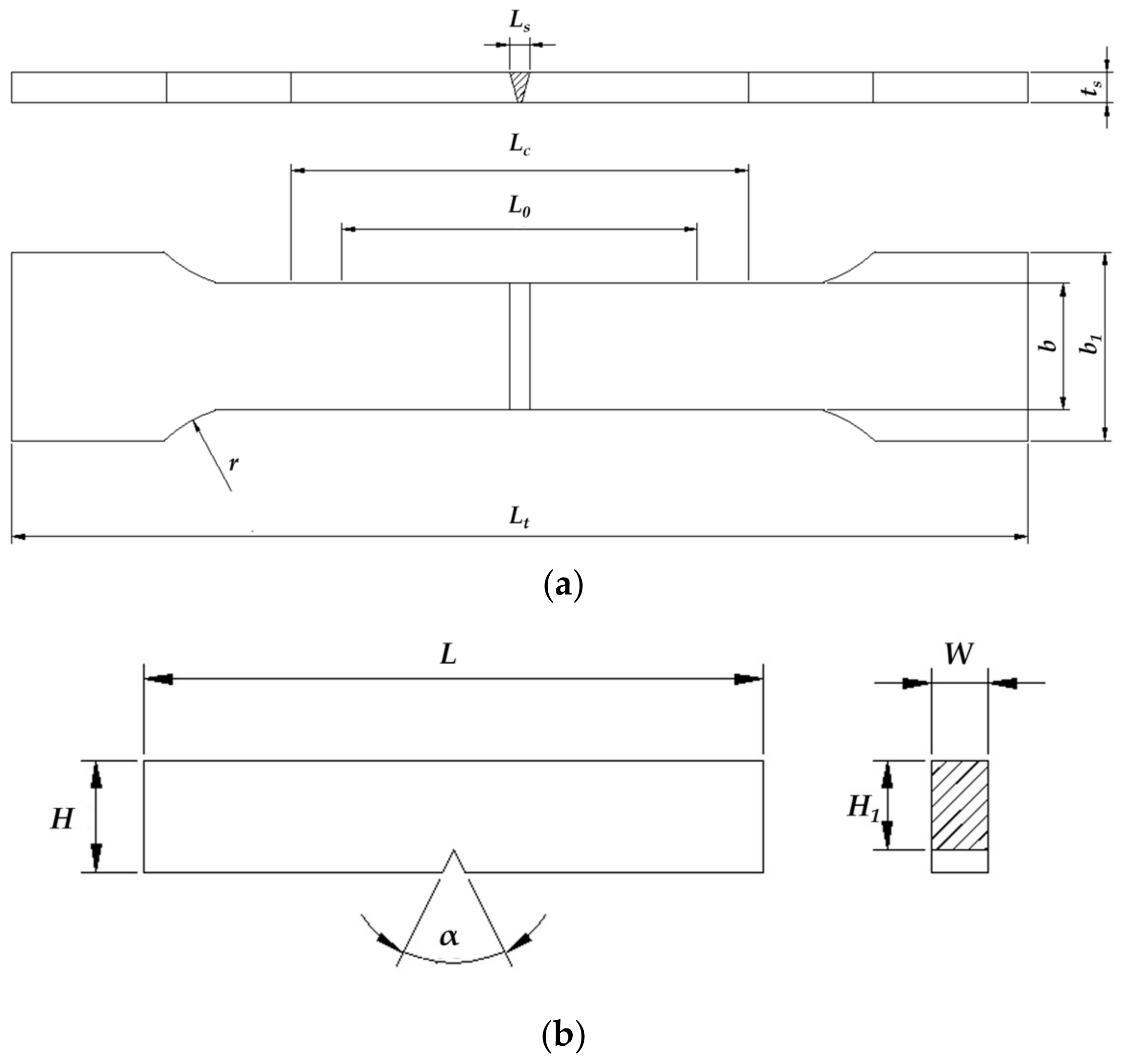
Mechanical tests were conducted to evaluate the performance–quality relationship. Flat tensile specimens were machined in strict accordance with GB/T 228.1-2021 (ISO 6892-1) [19,20]. The geometric parameters of the tensile specimen are listed as follows: total specimen length Lt = 200 mm, specimen thickness ts = 6 mm, parallel section width b = 25 mm, gripping end width b1 = 37 mm, transition filet radius r = 25 mm, parallel length Lc = 90 mm, and proportional original gauge length L0 = 70 mm. A clip-on extensometer with a gauge length of 50 mm and a measuring range of 0–5 mm was mounted on the parallel section to record strain data throughout tensile loading. The tensile tests were performed at a crosshead displacement rate of 2 mm/min, corresponding to an initial nominal strain rate of 6.67 × 10⁻⁴ s−1 based on the 50 mm gauge length. The load cell used had a rated capacity of 100 kN and an accuracy of class 0.5. The maximum width of the weld zone on the tensile specimen cross-section was measured to be Ls = 3.5 mm. One tensile specimen was prepared and tested at room temperature for each set of welding parameters, due to the limited size of the welded test plates available. Schematic diagrams of the dimensions of the specimens are presented in Figure 3a.
Given the research focus on low-temperature integrity, Charpy V-notch impact tests were carried out at −46 °C in accordance with the GB/T 229-2020 and GB/T 2650-2022 standards [21,22]. Three replicate impact samples were fabricated for both the weld center notch and HAZ notch under every heat input condition. All specimens were cooled to the target temperature using the built-in liquid nitrogen cooling system of the professional low-temperature impact tester, which ensures stable and accurate temperature control. Due to the limited thickness of the base metal (BM, 6 mm), small-sized Charpy V-notch impact specimens with dimensions of 55 mm × 10 mm × 5 mm were adopted. Figure 3b shows the dimensional drawing of the Charpy impact specimens. Impact V notches were machined at the weld center and the HAZ, respectively, so as to assess the toughness characteristics of the weld metal (WM) and HAZ microstructures separately. Finally, to understand the fracture mechanisms, the fracture surfaces of the broken impact specimens were analyzed using a Zeiss GEMINISEM 300 field emission scanning electron microscope (SEM, Carl Zeiss AG, Oberkochen, Germany).

3. Results

3.1. Microstructure Evolution of Welded Joints

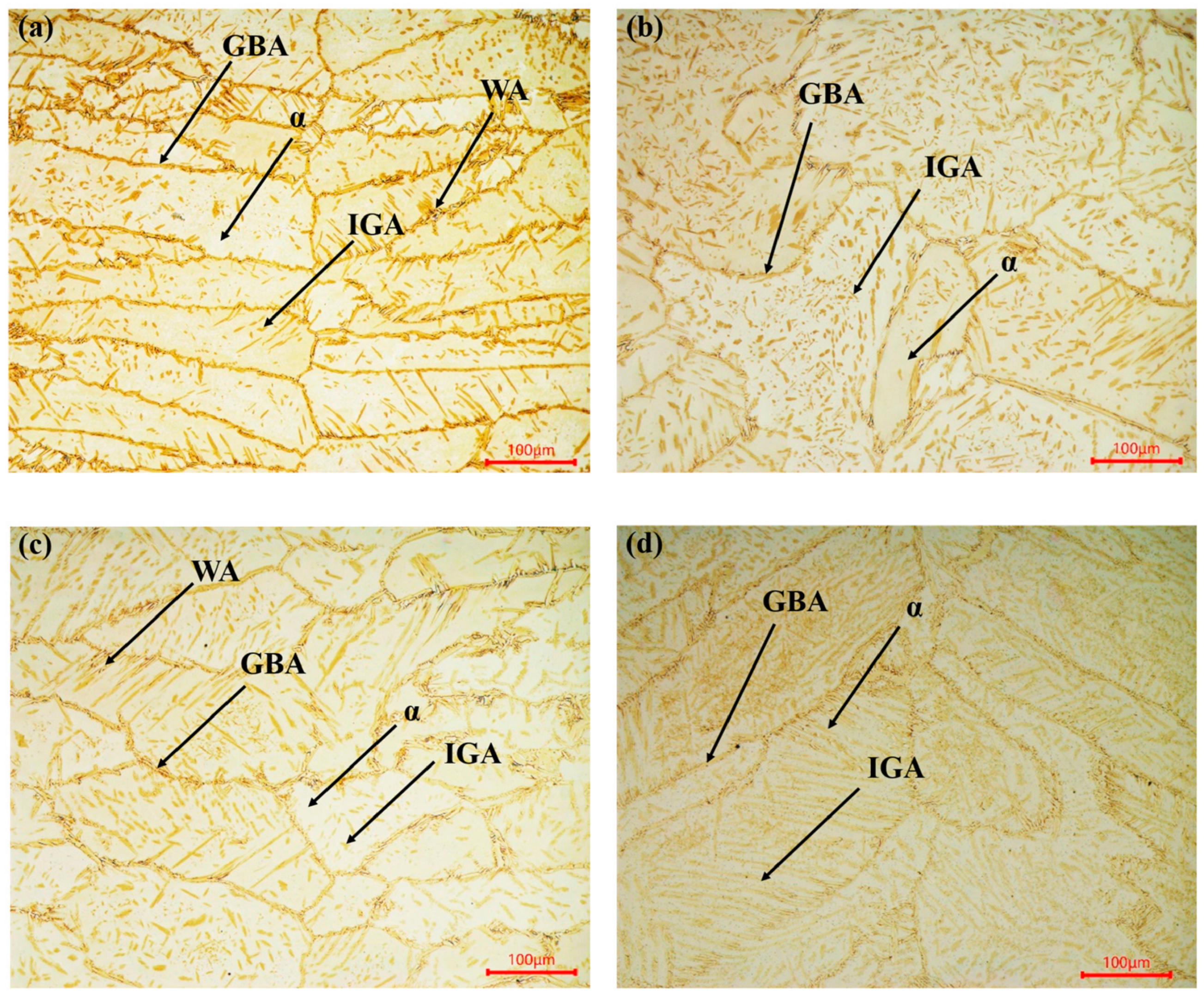
During welding, the WM of LAHW SAF2507 SDSS joints first solidifies as a fully ferritic phase. As the temperature decreases, austenite nucleates preferentially at ferrite grain boundaries and grows inward, forming grain boundary austenite (GBA) and Widmanstätten austenite (WA). Under moderate cooling rates, a small amount of intragranular austenite (IGA) can also form within ferrite grains. The final room-temperature microstructure consists of ferrite and austenite phases, with their fractions and morphologies strongly dependent on the welding heat input. The following sections analyze the microstructure of the WM and HAZ under different heat input conditions.

3.1.1. WM Microstructure

The WM is formed by the solidification of the molten pool, and its microstructure evolution is directly dominated by the cooling rate, which is precisely controlled by the welding heat input. The microstructure of the WM under different heat inputs consists of a bright white ferrite (α) matrix and dark gray austenite (γ) precipitates, which are consistent with the typical solidification and phase transformation characteristics of SDSS. The ferrite content of the WM was quantitatively measured by an F-2A ferrite tester.
Under low heat input conditions (Specimen 4, v = 1.2 m/min, Q = 0.204 kJ/mm), the cooling rate is the highest. The WM consists of fine equiaxed ferrite (bright white matrix). Austenite mainly exists as discontinuous GBA and dense acicular WA, which dispersedly divides the ferrite matrix. A small amount of IGA is also observed. Although the ferrite phase is fragmented visually, the actual volume fraction of ferrite reaches 68%, the highest among all groups. For Specimen 3 (v = 1.0 m/min, Q = 0.244 kJ/mm), the cooling rate is moderate. Ferrite grains grow slightly and become more connected. The number of acicular WA decreases, while IGA increases obviously. The measured ferrite fraction drops to 53%, and the two phases achieve an optimal balance.
The phase composition results of the WM under different heat inputs are summarized in Table 4. The ferrite and austenite contents are the average values of three repeated measurements. It can be seen that the austenite content in the WM increases with the increase in heat input, while the ferrite content decreases. This is because the increase in heat input reduces the cooling rate and prolongs the phase transformation time, which significantly promotes the diffusion of austenite-forming elements and the ferrite→austenite solid-state phase transformation, thus continuously increasing the austenite content in the final weld microstructure.
When the heat input is further increased (Specimen 2, v = 0.8 m/min, Q = 0.306 kJ/mm, high heat input; Specimen 1, v = 0.6 m/min, Q = 0.407 kJ/mm, ultra-high heat input), the cooling rate is further reduced, and the high-temperature residence time of the weld pool is prolonged. For Specimen 2, the austenite content increases to 52%, and the ferrite content decreases to 48%. The GBA becomes wider and more continuous, and a large number of long needle-like WA grows into the ferrite grains from the grain boundaries, with the ferrite grains showing an obvious coarsening trend (Figure 4c). For Specimen 1 with the highest heat input, the austenite content further increases to 58%, and the ferrite content decreases to 42%. The ferrite grains are severely coarsened, the GBA is thick and continuous, the grains are filled with dense, long, lath-like austenite, and some austenite phases are connected into sheets (Figure 4d). Meanwhile, the prolonged high-temperature residence time may create favorable conditions for the potential formation of detrimental brittle intermetallic phases along phase boundaries, which is reasonably inferred to deteriorate WM toughness.

3.1.2. HAZ Microstructure

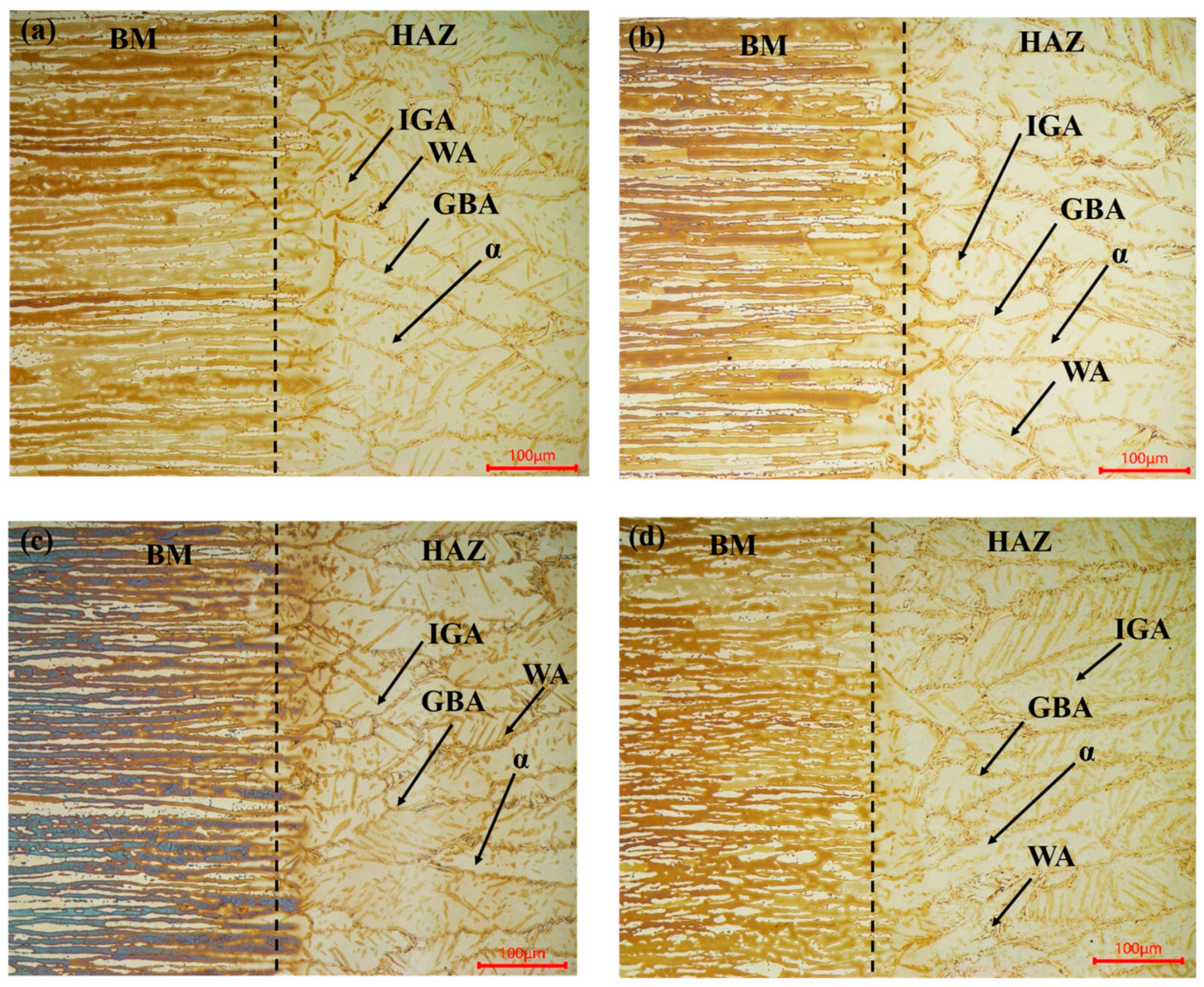
The HAZ is the transition region between the BM and WM, which is not melted during welding but undergoes a complex, non-equilibrium thermal cycle, resulting in significant microstructural evolution. The microstructural evolution of the HAZ under different welding heat inputs is presented in Figure 5. All micrographs are arranged with the BM on the left and the HAZ on the right, showing a continuous transition from the rolled BM structure to the recrystallized HAZ microstructure.
The BM exhibits a typical duplex stainless-steel microstructure, consisting of elongated, banded ferrite (bright white phase) and austenite (dark brown phase) aligned along the rolling direction. When subjected to welding thermal cycles, the BM structure transforms significantly in the HAZ.
As shown in Figure 5a (low heat input), the high cooling rate limits the recrystallization of ferrite grains and the precipitation of austenite. The original banded structure is partially retained near the BM side, while in the region closer to the fusion line, ferrite begins to recrystallize into fine equiaxed grains. Austenite mainly precipitates as discontinuous GBA and fine acicular WA, with only a small amount of IGA forming inside ferrite grains.
With the increase in heat input to medium (Figure 5b) and high levels (Figure 5c), the cooling rate decreases and the high-temperature residence time extends. Ferrite recrystallization becomes more complete, and the equiaxed ferrite grains gradually grow. Austenite precipitation is enhanced, with the fraction of IGA increasing significantly and the morphology of WA becoming coarser. The transition from the banded BM structure to the equiaxed HAZ structure becomes more obvious.
At an ultra-high heat input (Figure 5d), the HAZ experiences the longest high-temperature exposure. Ferrite grains are severely coarsened, and austenite precipitates in large quantities, forming a mixed morphology of GBA, coarse WA and abundant IGA. The high austenite fraction and severe grain coarsening under this condition may provide a favorable condition for the potential generation of brittle secondary phases, which is a plausible factor contributing to the degradation of HAZ low-temperature toughness.
Overall, the HAZ microstructure is highly sensitive to welding heat input. Increasing heat input promotes ferrite recrystallization and grain growth, as well as the precipitation of austenite in various forms. The evolution of these microstructural features directly affects the mechanical performance of the welded joint.

3.2. Mechanical Properties of Welded Joints

3.2.1. Tensile Properties

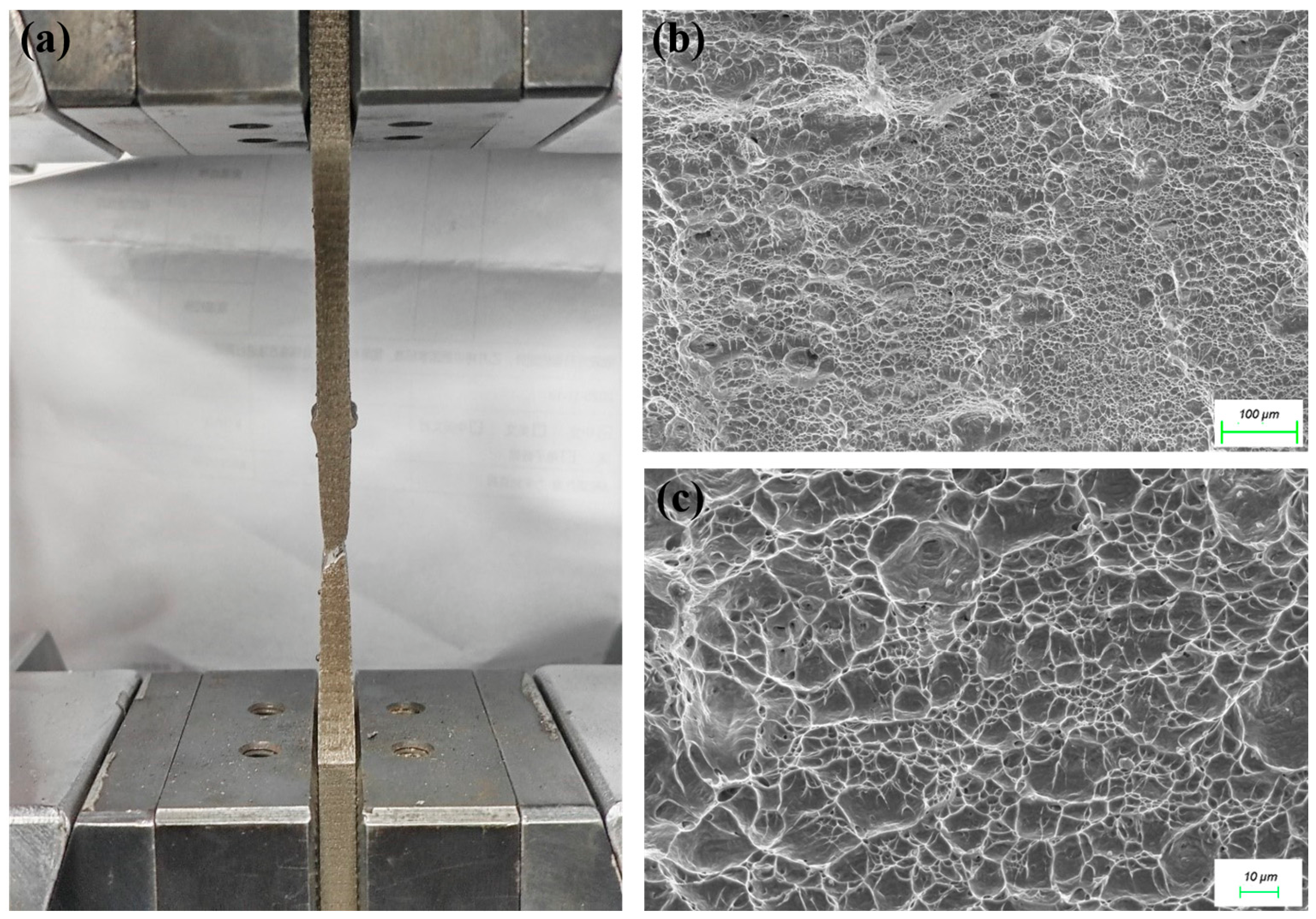
The tensile test results of LAHW SAF2507 SDSS joints under different heat inputs are summarized in Table 5. All tensile specimens fractured in the BM, as shown in Figure 6a, indicating that the weld joint has a higher tensile strength than the BM, which is consistent with the excellent weldability of LAHW for SDSS.
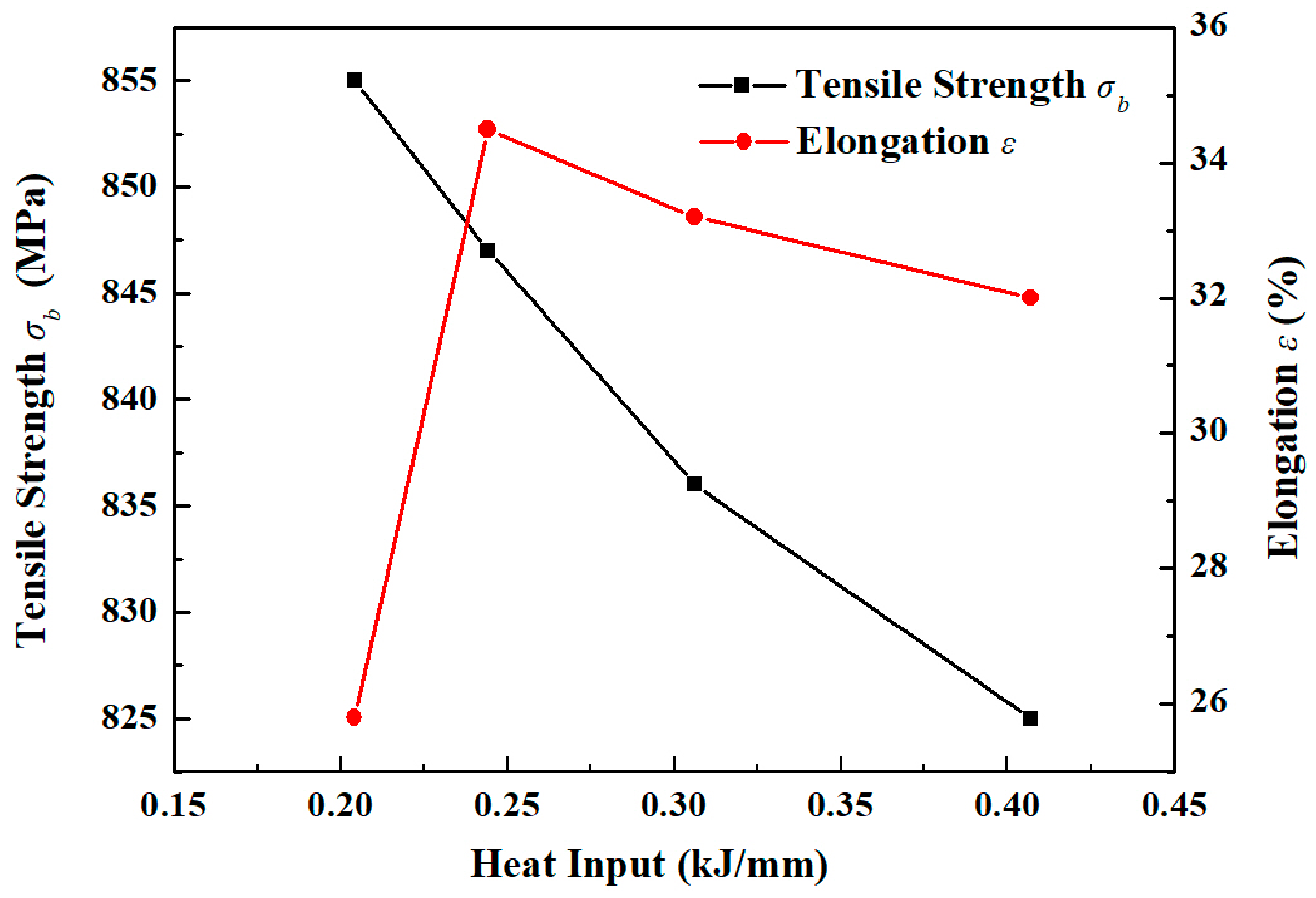
Variation in the tensile strength and elongation of welded joints with welding heat input is shown in Figure 7. With the increase in heat input, the tensile strength and yield strength of the joint show a slight downward trend, while the elongation after fracture shows a trend of first increasing and then decreasing. Under low heat input conditions (Specimen 4, v = 1.2 m/min, Q = 0.204 kJ/mm), the joint has the highest tensile strength (855 MPa) and yield strength (σs: 630 MPa), but the lowest elongation (ε: 25.8%). This is because the low heat input leads to a high ferrite content (68%) in the WM, which has high strength but low ductility.
With the increase in heat input, the austenite content in the WM increases, and the phase ratio becomes more balanced, leading to an increase in ductility (elongation increases). However, grain coarsening under high heat input leads to a slight decrease in tensile strength. For Specimen 3 (v = 1.0 m/min, Q = 0.244 kJ/mm, medium heat input), the joint has a good balance of tensile strength (σb: 847 MPa) and ductility (ε: 34.5%), which is the optimal heat input for tensile performance.
Fracture morphology analysis of Specimen 3 was performed via SEM to reveal the underlying fracture mechanism. The low-magnification SEM image (Figure 6b) shows a relatively flat fracture surface without obvious cleavage steps or brittle fracture features, confirming a dominant ductile fracture mode. High-magnification observations (Figure 6c) reveal a dense distribution of deep, equiaxed dimples across the entire fracture surface. These uniform, well-developed dimples indicate extensive plastic deformation prior to fracture, which effectively dissipates fracture energy and contributes to the high elongation of Specimen 3. This ductile fracture behavior is closely related to the balanced ferrite–austenite phase ratio and fine, uniform microstructure obtained under moderate heat input.
When the heat input is further increased (Specimen 2, v = 0.8 m/min, Q = 0.306 kJ/mm; Specimen 1, v = 0.6 m/min, Q = 0.407 kJ/mm), the tensile strength and yield strength continue to decrease slightly, while the elongation remains relatively high but declines slightly. This can be partly attributed to grain coarsening and the possible generation of harmful brittle intermetallic precipitates under prolonged high-temperature exposure. For Specimen 1 with the highest heat input, the tensile strength decreases to 825 MPa, and the elongation decreases to 32.0%, indicating that excessive heat input has a negative impact on both strength and ductility.

3.2.2. Low-Temperature Charpy Impact Toughness

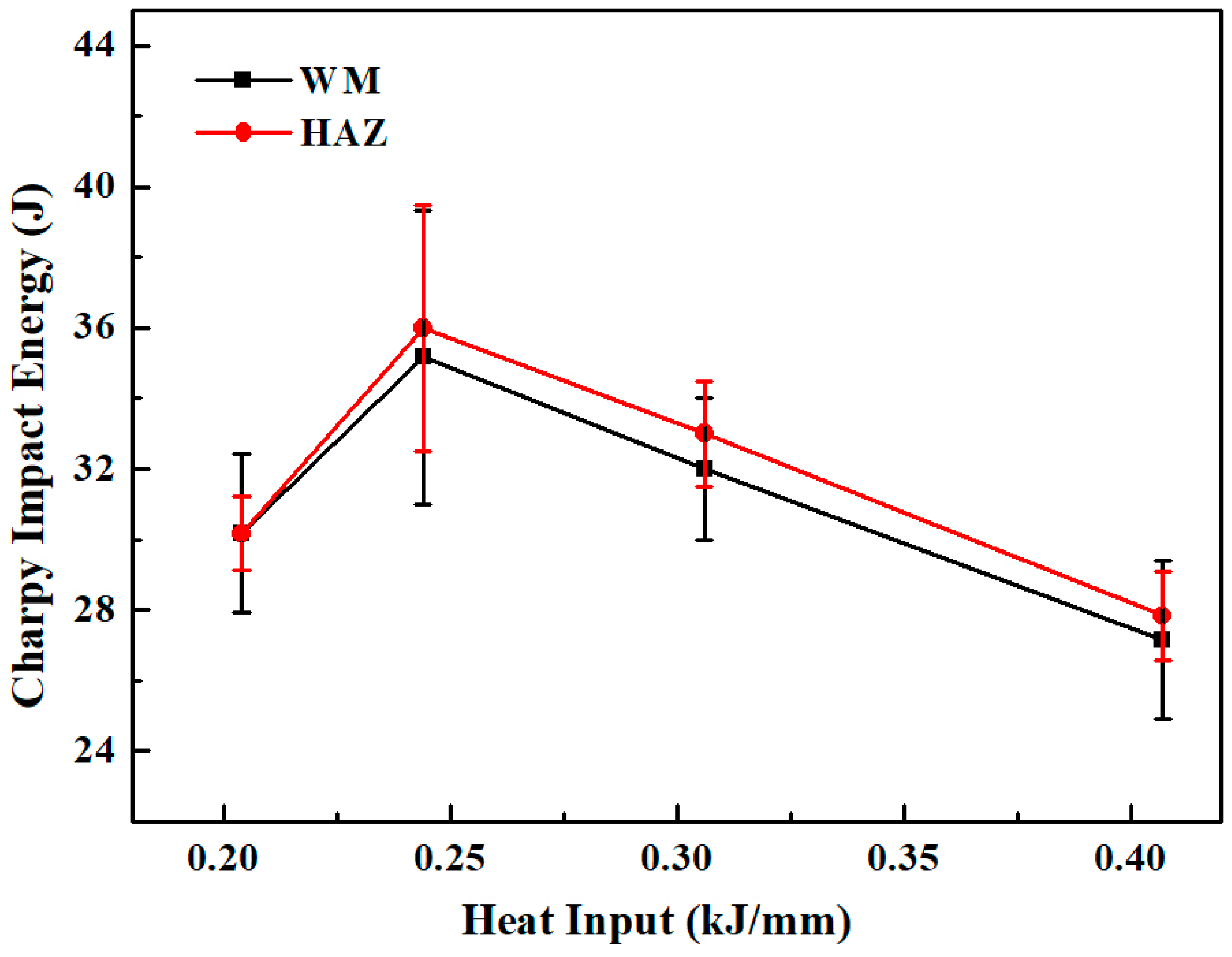
The −46 °C Charpy impact energy results are presented in Table 6 and Figure 8. The impact toughness of the joint exhibits a clear trend of first increasing and then decreasing with the rise in welding heat input, which is highly consistent with the microstructure evolution of the WM and HAZ analyzed above. The BM shows a superior average impact energy of 74.0 J, serving as a reliable performance benchmark for the welded joints.
Under low heat input conditions (Specimen 4, v = 1.2 m/min, Q = 0.204 kJ/mm), the joint possesses the lowest impact toughness, with average impact energies of 30.2 J for the weld center and 30.2 J for the HAZ. This is mainly attributed to the excessively high ferrite content (68%) and severely unbalanced phase ratio in the WM induced by rapid cooling under low heat input. The limited austenite phases fail to effectively hinder crack propagation, and the high cooling rate may also produce considerable residual stress within the joint, which could further degrade the low-temperature toughness.
With the increase in heat input to the medium level (Specimen 3, v = 1.0 m/min, Q = 0.244 kJ/mm), the joint reaches the peak impact toughness. The average impact energy of the weld center is 35.2 J, and that of the HAZ is 36.0 J, both being the highest among all welded specimens. This optimal toughness is ascribed to the nearly balanced ferrite–austenite phase ratio (approximately 53:47) and fine, uniform microstructure in both the weld and HAZ. The ductile austenite phases distributed along ferrite grain boundaries and inside grains can effectively blunt cracks and absorb impact energy, while the ferrite phase ensures the structural strength, realizing a perfect coordination of strength and toughness [6,11,23,24].
When the heat input is further increased to a high level (Specimen 2) and ultra-high level (Specimen 1), the impact toughness decreases noticeably. For Specimen 2, the average impact energies of the weld center and HAZ are 32.0 J and 33.0 J, respectively. For Specimen 1 with the maximum heat input (v = 0.6 m/min, Q = 0.407 kJ/mm), the average impact energies drop to 27.2 J (weld center) and 27.8 J (HAZ). This significant toughness degradation is attributed to excessive heat input, which leads to severe grain coarsening in both the WM and HAZ, weakening the grain boundary strengthening effect.
The impact test results fully demonstrate that moderate heat input is the key to obtaining excellent low-temperature impact toughness for SAF2507 SDSS LAHW joints. The welding parameter corresponding to Specimen 3 (welding speed 1.0 m/min, heat input 0.244 kJ/mm) is determined as the optimal parameter, which can meet the strict service requirements of low-temperature engineering scenarios.

3.2.3. Fracture Surface Analysis of the Impact Specimens

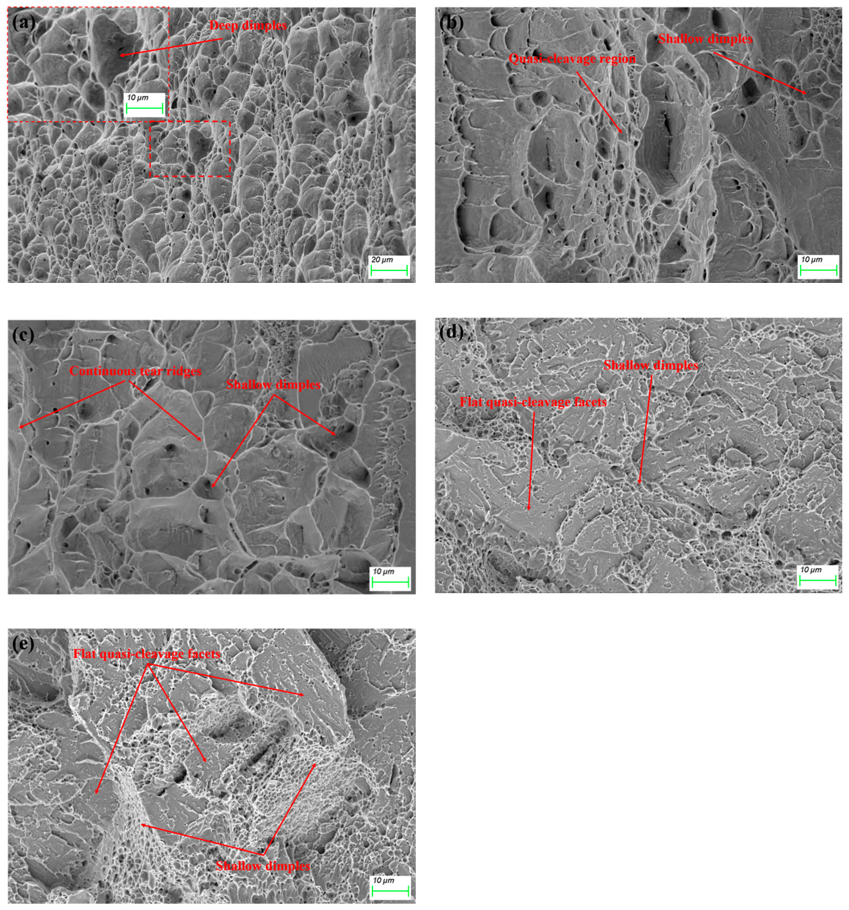
Impact tests were conducted on notched specimens machined at both the weld center and the HAZ. From an engineering regulation perspective, the WM toughness can be readily optimized by selecting matched high-toughness filler wires following the low-strength matching design principle, which improves ductility without obvious loss of joint strength. In contrast, the HAZ is the base metal region subjected to irreversible welding thermal cycles, and its microstructure and low-temperature toughness cannot be adjusted by filler metal. The only feasible method to regulate HAZ toughness is controlling welding heat input during manufacturing. Therefore, the HAZ represents the intrinsic weak toughness zone of the welded joint determined by thermal processing parameters, which is the core research object of this work. For this reason, the fractographic analysis mainly concentrates on HAZ fracture morphology to reveal the intrinsic correlation between heat input and joint toughness. The fracture surfaces of the BM and HAZ specimens under different heat inputs are shown in Figure 9. The BM exhibits a superior ductile fracture morphology, serving as the benchmark for the welded joints.
The BM fracture surface (Figure 9a) is characterized by a dense distribution of large, deep, equiaxed dimples of uniform size. These well-developed dimples indicate extensive plastic deformation prior to fracture, which effectively dissipates impact energy and contributes to the high average impact energy of 74.0 J. This ductile fracture behavior is attributed to the original balanced ferrite–austenite phase ratio and fine rolling microstructure of the as-received BM.
Under low heat input conditions (Specimen 4, v = 1.2 m/min, Q = 0.204 kJ/mm), the HAZ fracture surface shows a relatively flat morphology with shallow, sparse dimples and occasional cleavage-like ridges (Figure 9b). The dimples are small and poorly developed, and local regions exhibit quasi-cleavage features. This mixed fracture mode (quasi-cleavage + limited ductile dimples) aligns with the low impact energy (average Akv: 30.2 J). The excessively high ferrite fraction (68%) and unbalanced phase composition formed under rapid cooling deteriorate the plastic deformation capacity of the material, reducing crack resistance and resulting in premature fracture.
For Specimen 3 (medium heat input, v = 1.0 m/min, Q = 0.244 kJ/mm), the HAZ fracture surface is very rough and covered with a dense array of deep, uniform, and equiaxed dimples (Figure 9c). These well-defined dimples are uniformly distributed across the entire fracture surface, with clear tear ridges between adjacent dimples, indicating significant plastic deformation and energy absorption during impact loading. This typical ductile fracture mode is consistent with the highest impact energy (average Akv: 36.0 J) and is attributed to the balanced ferrite–austenite phase ratio (53% ferrite, 47% austenite) and fine, uniform microstructure in the HAZ.
When the heat input is further increased (Specimen 2, v = 0.8 m/min, Q = 0.306 kJ/mm; Specimen 1, v = 0.6 m/min, Q = 0.407 kJ/mm), the fracture morphology gradually transitions to a mixed mode of ductile dimples and intergranular brittle fracture. For Specimen 2, a large number of flat quasi-cleavage facets dominate the fracture surface, with scattered shallow small dimples distributed along the facet boundaries (Figure 9d). For Specimen 1 with the highest heat input, the fracture surface is covered by extensive flat quasi-cleavage facets, whose occupied area is remarkably larger than that of Specimen 2. Only sparse shallow dimples are sporadically distributed along the boundaries of these smooth cleavage planes (Figure 9e). A long high-temperature residence time at high heat input leads to obvious grain coarsening, leading to a significant reduction in impact toughness.
In summary, the fracture mechanism of the LAHW SAF2507 SDSS joints is closely related to the welding heat input. Under low heat input, the fracture is dominated by quasi-cleavage brittle fracture; under medium heat input, it is dominated by ductile dimple fracture; and under high heat input, it is a mixed fracture of ductile dimples and intergranular brittle fracture. It can be concluded that Specimen 3, with medium heat input, exhibits the best low-temperature impact toughness among the four groups of parameters.

3.3. Correlation Between Heat Input, Microstructure, and Mechanical Properties

Based on the above results, a clear correlation between the welding heat input, microstructure, and mechanical properties of LAHW SAF2507 SDSS joints has been established. Welding heat input directly governs the cooling rate, which in turn determines the phase transformation kinetics, grain size evolution, and precipitate formation behavior.
The ferrite→austenite solid-state phase transformation in SDSS is both thermally activated and diffusion-controlled [25,26]. As illustrated in Figure 4 and quantified in Table 4, the austenite content increases monotonically with heat input, from 32 vol.% at 0.204 kJ/mm to 58 vol.% at 0.407 kJ/mm. This trend can be explained by the competing effects of thermodynamic driving force and kinetic constraints. At low heat inputs (high cooling rates), although undercooling provides a strong driving force for phase transformation, the severely limited diffusion time for austenite-stabilizing elements (Ni, N) restricts austenite nucleation and growth to discontinuous grain boundary films [27,28]. This results in the excessively high ferrite content (68%) observed in Specimen 4.
As heat input increases to an intermediate level (0.244 kJ/mm, Specimen 3), the cooling rate becomes optimal for balancing these factors. The thermal cycle provides sufficient time for long-range diffusion of alloying elements while maintaining a sufficiently high cooling rate to prevent excessive grain coarsening. This enables both GBA and IGA to precipitate abundantly, achieving the near-ideal phase balance (53% ferrite, 47% austenite). The fine and uniform distribution of austenite within the ferrite matrix effectively partitions the microstructure, providing numerous interfaces that impede crack propagation and enhance impact toughness [23,29]. The observed correlation between austenite content and impact toughness aligns with the findings of Hu et al. [24,30], who reported that an optimal austenite fraction of 45–50 vol.% maximizes low-temperature impact energy in SDSS WM.
At excessively high heat inputs (0.306–0.407 kJ/mm, Specimens 1–2), the cooling rate becomes too slow. While this further promotes austenite formation (up to 58%), two detrimental effects emerge. First, the prolonged high-temperature residence time leads to significant coarsening of both ferrite grains and austenite precipitates (Figure 4c,d), weakening grain boundary strengthening. Second, the prolonged high-temperature holding time deteriorates the interfacial bonding between different phases. These microstructural changes may cause severe stress concentration and accelerate crack propagation under impact loading, explaining the sharp decline in impact toughness from 36.0 J (Specimen 3) to 27.8 J (Specimen 1) despite the more balanced phase ratio.
The observed toughness degradation at high heat inputs is consistent with the findings of Li et al. [31,32]. Their studies indicated that prolonged high-temperature residence during slow cooling will cause continuous grain coarsening in super-duplex stainless-steel welds, which severely deteriorates the impact resistance. Meanwhile, Acuna et al. [33] pointed out that an excessively low cooling rate leads to undesirable microstructural evolution and brittle fracture characteristics in SDSS joints. In this work, the cooling rate of Specimen 1 (0.407 kJ/mm) with ultra-high heat input is excessively low, which well explains the typical intergranular fracture features shown in Figure 9e.
From an engineering perspective, these findings have direct implications for welding procedure specification in low-temperature service applications. For SAF2507 SDSS components intended for Arctic or deep-sea environments (design temperatures as low as −46 °C to −60 °C), the welding heat input should be carefully controlled within an optimal window. Based on the present results, a heat input of 0.24–0.25 kJ/mm (corresponding to a welding speed of 1.0 m/min under the current parameter set) is recommended. This range ensures (i) sufficient austenite reformation (45–50 vol.%) to provide crack-arresting capability and (ii) a fine grain size to maximize grain boundary strengthening. For thicker sections (>10 mm), preheating and interpass temperature control might be required to maintain a comparable optimal cooling rate, while for thinner sections, lower heat input could be needed to avoid excessive ferrite content. The above inferences regarding plates with different thicknesses are only preliminary engineering suggestions, and dedicated verification experiments on plates of other thicknesses are still required to confirm these speculations.
Therefore, reasonable control of welding heat input is critical to obtain LAHW SAF2507 SDSS joints with uniform microstructure and good comprehensive mechanical properties, especially low-temperature toughness. The parameter of 0.244 kJ/mm obtained in this work can serve as a practical reference for the formulation of relevant industrial welding procedures.

4. Conclusions

Based on a systematic investigation of the effect of welding heat input on the microstructure and low-temperature toughness of LAHW SAF2507 SDSS joints, the following conclusions are drawn:
  • Welding heat input has a significant effect on the microstructure of LAHW SAF2507 SDSS joints. With the increase in heat input, the austenite content in the WM and HAZ increases, the ferrite content decreases, and the grain size first refines and then coarsens.
  • The tensile properties of the joint are slightly affected by heat input. All joints fracture in the BM, indicating that the weld joint has higher tensile strength than the BM. The tensile strength and yield strength decrease slightly with increasing heat input, while the elongation increases slightly, and medium heat input achieves the best balance of strength and ductility.
  • The low-temperature impact toughness of the joint exhibits a clear peak at intermediate heat input. The optimal condition (welding speed 1.0 m/min, heat input 0.244 kJ/mm) produced the highest Charpy impact energies of 35.2 J (weld center) and 36.0 J (HAZ) at −46 °C, corresponding to a balanced ferrite/austenite phase ratio of 53:47 with fine, uniformly distributed austenite. Deviation from this optimum degraded toughness: low heat input (0.204 kJ/mm) yielded only 30.2 J due to excessive ferrite content (68%), while high heat input (0.407 kJ/mm) reduced toughness to 27.8 J because of grain coarsening.
  • The fracture mechanism is strongly dependent on the heat input level: low heat input leads to mixed brittle–ductile fracture, medium heat input leads to ductile dimple fracture, and high heat input leads to mixed ductile–intergranular brittle fracture.
  • Within the present test range, the welding heat input of 0.244 kJ/mm (welding speed of 1.0 m/min) shows preferable performance for LAHW of SAF2507 SDSS. This parameter yields joints with a near-ideal phase balance (53% ferrite, 47% austenite) and fine grain size, achieving a superior combination of tensile strength (847 MPa), ductility (34.5% elongation), and low-temperature toughness (36.0 J at −46 °C), thereby meeting the stringent requirements of critical low-temperature service environments such as Arctic pipelines and offshore structures.

Author Contributions

Conceptualization, S.Z. and L.B.; Methodology, L.B. and J.S.; Validation, L.B.; Formal Analysis, S.Z.; Investigation, S.Z.; Resources, S.Z. and L.B.; Data Curation, S.Z. and J.S.; Writing—Original Draft, S.Z.; Writing—Review and Editing, L.B.; Project Administration, S.Z.; Funding Acquisition, S.Z. and L.B. All authors have read and agreed to the published version of the manuscript.

Funding

This research was funded by THE KEY SCIENTIFIC RESEARCH PROJECT OF THE ANHUI PROVINCIAL DE-PARTMENT OF EDUCATION, grant number 2025AHGXZK30465 and THE KEY PROJECT OF NATURAL SCI-ENCE RESEARCH FOR UNIVERSITIES IN ANHUI PROVINCE, grant number KJ2020A1105.

Data Availability Statement

The original contributions presented in this study are included in the article. Further inquiries can be directed to the corresponding author.

Conflicts of Interest

The authors declare that they have no conflicts of interest.

Nomenclature

The following abbreviations and symbols are used in this manuscript:
SDSSSuper-Duplex Stainless-Steel
LAHWLaser-Arc Hybrid Welding
BMBase Metal
WMWeld Metal
HAZHeat-Affected Zone
GBAGrain Boundary Austenite
WAWidmanstätten Austenite
IGAIntragranular Austenite
SEMScanning Electron Microscope
αFerrite Phase
γAustenite Phase
σβTensile Strength
σsYield Strength
εElongation After Fracture
AkvCharpy Impact Energy
QWelding Heat Input
ηWelding Thermal Efficiency
PlaserLaser Lower
IWelding Current
UWelding Voltage
vWelding Speed

References

  1. Yuan, Y.; Yuan, S.; Wang, Y.; Li, Q.; Deng, Z.; Xie, Y.; Ke, Y.; Xu, J.; Yu, H.; Sun, D. Nanostructure, Mechanical Properties, and Corrosion Resistance of Super Duplex Stainless Steel 2507 Aged at 500 °C. Crystals 2023, 13, 243. [Google Scholar] [CrossRef]
  2. Shin, B.-H.; Kim, D.; Yoon, J.-H. Crystallization of Secondary Phase on Super-Duplex Stainless Steel SAF2507: Advanced Li-Ion Battery Case Materials. Crystals 2024, 14, 378. [Google Scholar] [CrossRef]
  3. Wang, Q.; Gu, G.C.; Jia, C.B.; Li, K.; Wu, C.S. Investigation of Microstructure Evolution, Mechanical and Corrosion Properties of SAF 2507 Super Duplex Stainless Steel Joints by Keyhole Plasma Arc Welding. J. Mater. Res. Technol. 2023, 22, 355–374. [Google Scholar] [CrossRef]
  4. Sharma, L.; Sharma, K. Dissimilar welding of super duplex stainless steel (SDSS) and pipeline steel—A brief overview. In Materials Today: Proceedings; Elsevier: Amsterdam, The Netherlands, 2022. [Google Scholar]
  5. Khan, W.N.; Chhibber, R. Effect of filler metal on solidification, microstructure and mechanical properties of dissimilar super duplex/pipeline steel GTA weld. Mater. Sci. Eng. A 2021, 803, 140476. [Google Scholar] [CrossRef]
  6. Zhang, Z.Q.; Chu, H.R.; Zhang, T.G.; Xu, L.Y.; Lu, X.C.; Qu, S.C.; Liu, B. Microstructural Evolution and Its Influence on Low-Temperature Toughness of Simulated Heat-Affected Zone in Super Duplex Stainless Steel Welded Joint. Steel Res. Int. 2024, 95, 202300460. [Google Scholar] [CrossRef]
  7. Xu, L.Y.; Bai, Y.J.; Han, Y.D.; Jing, H.Y.; Zhang, Z.Q. Microstructure Characteristics of Duplex Stainless Steel CMT-P Composite Welding. Trans. China Weld. Inst. 2022, 43, 1–6. [Google Scholar]
  8. Yıldızlı, K. Investigation on the Microstructure and Toughness Properties of Austenitic and Duplex Stainless Steels Weldments under Cryogenic Conditions. Mater. Des. 2015, 77, 83–94. [Google Scholar] [CrossRef]
  9. Ajenifuja, E.; Popoola, A.P.I.; Popoola, O. Comparative Analysis of Structural and Mechanical Properties of Duplex Stainless Steel (DSS) Weldments Prepared by Flux Core Arc Welding and Shielded Metal Arc Welding Processes. J. Adv. Join. Process. 2025, 11, 100295. [Google Scholar] [CrossRef]
  10. Šimeková, B.; Dománková, M.; Kovaříková, I.; Kovačócy, P.; Martinkovič, M.; Šimek, M.; Ciuła, L. Microstructural and Mechanical Characterization of the Laser Beam Welded SAF 2507 Super-Duplex Stainless Steel. Metals 2024, 14, 1184. [Google Scholar] [CrossRef]
  11. Hu, X.; Qin, L.; Wang, H.; Zhang, L.; Xie, X. Microstructure Formation and Its Effect on Mechanical Properties for Duplex Stainless Steel 2205 Plasma Arc Welded Joint. Metals 2024, 14, 68. [Google Scholar] [CrossRef]
  12. Acherjee, B. Hybrid Laser Arc Welding: State-of-Art Review. Opt. Laser Technol. 2018, 99, 60–71. [Google Scholar] [CrossRef]
  13. Bao, L.L.; Wang, Y.; Han, T. Study on Microstructure-Toughness Relationship in Heat Affected Zone of EQ70 Steel by Laser-Arc Hybrid Welding. Mater. Charact. 2021, 171, 110788. [Google Scholar] [CrossRef]
  14. He, Y.; Song, X.; Yang, Z.; Duan, R.; Xu, J.; Wang, W.; Chen, L.; Shi, M.; Chen, S. Research and Development Progress of Laser–Arc Hybrid Welding: A Review. Metals 2025, 15, 326. [Google Scholar] [CrossRef]
  15. Bunaziv, I.; Akselsen, O.M.; Frostevarg, J.; Kaplan, A.F.H. Application of Laser-Arc Hybrid Welding of Steel for Low-Temperature Service. Int. J. Adv. Manuf. Technol. 2019, 102, 2601–2613. [Google Scholar] [CrossRef]
  16. Abdo, H.S.; Seikh, A.H. Mechanical Properties and Microstructural Characterization of Laser Welded S32520 Duplex Stainless Steel. Materials 2021, 14, 5532. [Google Scholar] [CrossRef] [PubMed]
  17. Krawczyk, R.; Słania, J.; Golański, G.; Pfeifer, T. Mechanical Properties and Microstructure of Austenite—Ferrite Duplex Stainless Steel Hybrid (Laser + GMAW) and SAW Welded Joint. Materials 2023, 16, 2909. [Google Scholar] [CrossRef] [PubMed]
  18. Akyel, F.; Üstündag, Ö.; Bakir, N.; Brunner-Schwer, C.; Gumenyuk, A.; Rethmeier, M. Influence of Heat Input on Cooling Rates and Mechanical Properties of Laser Hybrid Welded Thick Structural Steels. Weld. World 2025, 69, 1813–1827. [Google Scholar] [CrossRef]
  19. GB/T 229-2020; Metallic Materials—Charpy Pendulum Impact Test Method. State Administration for Market Regulation. Standardization Administration of China: Beijing, China, 2020.
  20. GB/T 2650-2022; Destructive Tests on Welds in Metallic Materials—Impact Tests. State Administration for Market Regulation. Standardization Administration of China: Beijing, China, 2022.
  21. GB/T 228.1-2021; Metallic Materials—Tensile Testing—Part 1: Method of Test at Room Temperature. State Administration for Market Regulation. Standardization Administration of China: Beijing, China, 2021.
  22. ISO 6892-1:2019; Metallic Materials—Tensile Testing—Part 1: Method of Test at Room Temperature. International Organization for Standardization: Geneva, Switzerland, 2019.
  23. Wang, B.J.; Zhang, Y.P.; Shen, X.J.; Huan, P.C.; Zhang, Q.Y.; Wang, X.N. Austenite Morphology and Distribution Dependence of Impact Toughness in S32101 Duplex Stainless Steel Laser Welds. Metall. Mater. Trans. A 2024, 55, 1183–1192. [Google Scholar] [CrossRef]
  24. Hu, Y.; Shi, Y.; Wang, K.; Huang, J. Effect of Heat Input on the Microstructure and Mechanical Properties of Local Dry Underwater Welded Duplex Stainless Steel. Materials 2023, 16, 2289. [Google Scholar] [CrossRef] [PubMed]
  25. Pezzato, L.; Calliari, I. Advances in Duplex Stainless Steels. Materials 2022, 15, 7132. [Google Scholar] [CrossRef] [PubMed]
  26. Yamashita, S.; Ike, K.; Yamasaki, K. Relationship between Ferrite–Austenite Phase Transformation and Precipitation Behavior of Sigma Phase in Super Duplex Stainless Steel Weldment. Weld. World 2022, 66, 351–362. [Google Scholar] [CrossRef]
  27. Kugelmeier, C.L.; Silva, R.; Mendes Filho, A.A.; Magnabosco, R.; Kliauga, A.M.; Rovere, C.A.D. Gleeble® Simulation of the Heat-Affected Zones in Lean Duplex Stainless Steel 2404: Understanding the Effect of Cooling Rates on Microstructure Evolution and Pitting Corrosion Resistance. J. Mater. Res. Technol. 2024, 33, 7518–7533. [Google Scholar] [CrossRef]
  28. Wu, X.H.; Nai, Q.L.; Han, F.; Yao, L.; Wu, M.H.; Wang, B.S.; Song, Z.G.; Zheng, W.J. Morphologies of Secondary Austenite in 2507 Duplex Stainless Steel after Heat Treatment. J. Iron Steel Res. Int. 2022, 29, 994–1003. [Google Scholar]
  29. Gerosa, R.; Panzeri, D.; Rivolta, B. Influence of Microstructure on the 2507 Duplex Stainless Steel Toughness. Eng. Fract. Mech. 2026, 335, 111937. [Google Scholar] [CrossRef]
  30. Kwon, D.Y.; Na, H.S.; Choi, J.Y.; Kang, J.H. Effect of Annealing Temperature on Tensile and Impact Properties of S31803 Duplex Stainless Steel. Mater. Sci. Eng. A 2025, 931, 148222. [Google Scholar] [CrossRef]
  31. Li, H.W.; Zhao, Z.Y.; Xue, R.D. Effect of Heat Input on the Microstructure and Hardness of SAF2507 Super Duplex Stainless Steel Welded Joints. Trans. China Weld. Inst. 2022, 43, 20–26. [Google Scholar]
  32. Arun, D.; Ramkumar, K.D.; Vimala, R. Multi-Pass Arc Welding Techniques of 12 mm Thick Super Duplex Stainless Steel. J. Mater. Process. Technol. 2019, 271, 126–143. [Google Scholar] [CrossRef]
  33. Acuna, A.; Ramirez, A.; Riffel, K.C. Using kinetics to avoid sigma phase formation on hyper duplex stainless weld cladding. Sci. Technol. Weld. Join. 2023, 28, 885–893. [Google Scholar] [CrossRef]
Figure 1. The microstructure of the as-received SAF2507 SDSS.
Metals 16 00787 g001
Figure 2. Laser-arc hybrid welding torch. (a) Schematic diagram; (b) physical photo.
Metals 16 00787 g002
Figure 3. Dimensional schematic diagram. (a) Flat tensile specimen, where Lt = total length of specimen (200 mm), Lc = parallel length (90 mm), L0 = proportional original gauge length (70 mm), Le = extensometer gauge length (50 mm), b = width of parallel section (25 mm), b1 = width of gripping part (37 mm), r = transition arc radius (25 mm), ts = specimen thickness (6 mm), and Ls = maximum width of weld seam on specimen cross-section (3.5 mm); (b) Charpy impact specimens, where L = length of specimen (55 mm), W = width (thickness) of specimen (5 mm), H = height of specimen (10 mm), and H1 = height below the V notch (8 mm); α = V notch angle (45°).
Metals 16 00787 g003
Figure 4. Microstructure of WM under different heat inputs. (a) Specimen 4 (1.2 m/min, low heat input); (b) Specimen 3 (1.0 m/min, medium heat input); (c) Specimen 2 (0.8 m/min, high heat input); (d) Specimen 1 (0.6 m/min, ultra-high heat input).
Metals 16 00787 g004
Figure 5. Microstructure of HAZ under different heat inputs. (a) Specimen 4 (1.2 m/min, low heat input); (b) Specimen 3 (1.0 m/min, medium heat input); (c) Specimen 2 (0.8 m/min, high heat input); (d) Specimen 1 (0.6 m/min, ultra-high heat input).
Metals 16 00787 g005
Figure 6. Tensile fracture characteristics of Specimen 3 (medium heat input). (a) Macrograph of the tensile specimen showing fracture in the BM; (b) low-magnification SEM image of the fracture surface (500×); (c) high-magnification SEM image showing dense equiaxed dimples (2500×).
Metals 16 00787 g006
Figure 7. Variation in tensile strength and elongation of welded joints with welding heat input.
Metals 16 00787 g007
Figure 8. Charpy impact energies of LAHW SAF2507 SDSS joints at −46 °C.
Metals 16 00787 g008
Figure 9. SEM fracture surface morphology of impact specimens at −46 °C. (a) BM (500×): the upper-left dashed box indicates the cropped region for the central embedded inset, which shows the fracture features at an equivalent 1000× scale with a standard 10 μm scale bar; (b) Specimen 4 (low heat input, HAZ, 1000×); (c) Specimen 3 (medium heat input, HAZ, 1000×); (d) Specimen 2 (high heat input, HAZ, 1000×); (e) Specimen 1 (ultra-high heat input, HAZ, 1000×).
Metals 16 00787 g009
Table 1. Chemical composition of SAF2507 SDSS (wt.%).
CMnSiPSCrNiNMoFe
0.031.20.80.0350.0224–266–80.24–0.323–5else
Table 2. Chemical composition of ER2594 filler wire (wt.%).
CMnSiCrNiNMoFe
0.020.40.35259.50.254else
Table 3. Welding parameters.
Specimen
No.
Welding Speed
(m/min)
Laser Power
(W)
Current
(A)
Voltage
(V)
Beam to Wire
(mm)
Defocus
(mm)
Heat Input (kJ/mm)
10.6300014314.71200.407
20.8300014314.71200.306
31.0300014314.71200.244
41.2300014314.71200.204
Table 4. The phase composition of WM under different welding heat inputs.
Specimen No.Welding Speed (m/min)Heat Input (kJ/mm)Ferrite Content (vol.%)Austenite Content (vol.%)
10.60.4074258
20.80.3064852
31.00.2445347
41.20.2046832
Table 5. Tensile properties of LAHW SAF2507 SDSS joints at different heat inputs.
Specimen No.Welding Speed (m/min)Heat Input (kJ/mm)Tensile Strength σb (MPa)Yield Strength σs (MPa)Elongation ε (%)Fracture Position
10.60.40782560532.0BM
20.80.30683661533.2BM
31.00.24484762234.5BM
41.20.20485563025.8BM
Table 6. Charpy impact toughness of LAHW SAF2507 SDSS welded joints at −46 °C.
Specimen No.Testing
Position
Test Impact Energy (J)Average Akv (J)
BMBM 74767274.0
4Weld Center 32.530.028.030.2
4HAZ30.529.031.030.2
3Weld Center 38.536.530.535.2
3HAZ37.532.038.536.0
2Weld Center 34.032.030.032.0
2HAZ33.031.534.533.0
1Weld Center 29.527.025.027.2
1HAZ28.026.529.027.8
Disclaimer/Publisher’s Note: The statements, opinions and data contained in all publications are solely those of the individual author(s) and contributor(s) and not of MDPI and/or the editor(s). MDPI and/or the editor(s) disclaim responsibility for any injury to people or property resulting from any ideas, methods, instructions or products referred to in the content.