Abstract
The anodic oxidation technique was used for surface modification, resulting in the creation of a titanium-based nanotube oxide layer on a coarse-grained and ultrafine-grained Ti-13Nb-13Zr alloy. The modified surface morphology was analyzed using scanning electron microscopy (SEM), atomic force microscopy (AFM), and X-ray diffraction (XRD). The electrochemical impedance spectroscopy (EIS) method was employed to evaluate the corrosion stability of the Ti-13Nb-13Zr alloy before and after anodic oxidation. Corrosion stability was determined by exposing the examined alloy to a solution that simulates environment in the human organism (Ringer’s solution). To examine the titanium-based nanotube oxide layer adhesion on the Ti-13Nb-13Zr alloy’s surface, a scratch test was performed. The hydrophilicity of the modified surface was measured using the contact angle between a drop of Ringer’s solution and the modified surface. The anodic oxidation led to the creation of a nanotube oxide layer on the surface of the Ti-13Nb-13Zr (wt.%) alloy. The impact of the ultrafine-grained structure on the homogeneity of the nanotube oxide layer obtained using anodic oxidation was observed. The ultrafine-grained structure contributed to the increased diameter of the nanotubes, while the combined effect of anodic oxidation and high-pressure torsion significantly increased the roughness of the Ti-13Nb-13Zr alloy’s surface, which is expected to enhance biomechanical compatibility by reducing cytotoxicity, providing a more adaptable modulus of elasticity for human body conditions and ensuring adequate corrosion resistance and hydrophilicity. In this study, it was established that the examined alloy had suitable corrosion resistance for utilization in medicine as a metallic implant in the human body. The scratch test showed acceptable adhesion from the titanium-based nanotube oxide layer created using anodic oxidation. Also, the determination of the surface contact angle showed that the surface after anodic oxidation was more hydrophilic than the surface before anodic oxidation.
1. Introduction
1.1. Titanium-Based Biomaterials
Titanium and its alloys have been extensively scientifically researched and used for biomedical applications, primary for metallic implants due to their favorable combination characteristics: biocompatibility, low density, good corrosion behavior, and adequate mechanical properties [1,2,3]. Compositions of titanium alloys with titanium (Ti), niobium (Nb), and zirconium (Zr) allow for improved strength, enhanced corrosion resistance, and better bioactivity than other titanium alloys [1,4,5]. Also, the Ti-13Nb-13Zr alloy exhibits an attractive combination of mechanical properties, low modulus of elasticity, and resistance to fatigue, making it highly appropriate for long-term implant applications in the human body [1,6,7] and more suitable for applications that demand materials that better match the stiffness of bone and reduce the risk of stress shielding [8]. Additionally, Ti-13Nb-13Zr exhibits superior corrosion resistance, good tensile characteristics (high yield strength and low modulus of elasticity) and biocompatibility, making it a promising candidate for implants in the human body [4,9]. Lee et al. [8] investigated the mechanical characteristics of Ti-13Nb-13Zr alloys produced using different manufacturing processes and noticed that the modulus of elasticity could be reduced, while the mechanical compatibility could be considered adequate for biomedical application [10]. Ke et al. [11] showed that addition of Cu as an alloying element in a Ti-13Nb-13Zr alloy can lead to excellent mechanical characteristics and high antibacterial activity. It was shown that the corrosion stability of the Ti-13Nb-13Zr alloy in a simulated human body solution is adequate for biomedical application and is better than a Ti-6Al-6V alloy and commercially pure titanium [12,13].
1.2. Surface Modification of Titanium Alloys
Regardless of above-mentioned advantages, the characteristics of the Ti-13Nb-13Zr alloy can be additionally enhanced using surface modification [14,15,16,17,18,19,20]. The efficiency of titanium alloys for medical applications is significantly influenced by their surface characteristics [21]. Various methods have been developed for surface modification of titanium alloys to modify their surface characteristics, such as anodic oxidation (AO), plasma electrolytic oxidation (PEO), ion implantation plasma treatment, and laser surface modification [22,23,24]. Anodic oxidation is one of the most widely studied and applied surface modification methods for titanium alloys. Anodic oxidation involves using a current density to form a controlled stable oxide layer, consisting of nanotubes or nanopores, on the surfaces of titanium alloys [25,26]. By controlling the anodic oxidation parameters—voltage, electrolyte composition, current density, and anodic oxidation time—the thickness of the oxide layer, nanotube/nanopore dimensions (wall thickness, diameter, and length of the nanotubes/nanopores), surface porosity, and the crystalline structure of the modified surface can be tailored to meet specific requirements for biomedical applications [27,28,29,30]. This oxide layer, mainly composed of titanium dioxide (TiO2), leads to the enhancement of several important surface characteristics—surface modulus of elasticity, corrosion stability, and biocompatibility—and potentially increases surface roughness, which can improve cellular attachment and osseointegration [31,32,33,34]. The anodized surface can also be made to exhibit increased hydrophilicity, which is beneficial for protein and cell adhesion. Zhong et al. [35] noticed that the AO of a Ti-13Nb-13Zr alloy notably enhances the corrosion stability by forming a dense and stable oxide layer that behaves like a protective barrier against the environment of the human body. Additionally, they showed that anodic oxidation can increase the hydrophilicity of the surfaces of titanium-based materials, while the parameters of anodic oxidation process have a significant influence on both surface characteristics: corrosion resistance and hydrophilicity [35]. Many studies show that modified surfaces of the titanium alloys lead to improved corrosion resistance [36,37,38]. Further, a modified surface is a key part in achieving the better biocompatibility, adhesion, and proliferation of cells and in enhancing the osseointegration process [16,17,18,39]. The surfaces roughness of titanium alloys obtained using anodic oxidation can be controlled at the microscale or nanoscale, influencing cellular behavior. A rougher surface can enhance the biomechanical interlocking between the metallic implant and surrounding bone tissue, leading to better osseointegration [39]. Titanium alloys are subject to wear and damage in clinical applications. Surface modification improves the wear stability of titanium-based materials, especially when combined with other techniques such as severe plastic deformation (SPD).
1.3. High-Pressure Torsion (HPT) and Surface Modification of Titanium Alloys
High-pressure torsion (HPT) is a severe plastic deformation (SPD) technique that is commonly used to refine the structure of metallic materials by imparting ultrafine with submicron (100 nm–1000 nm) or nanocrystalline (<100 nm) grains in the structure of metallic materials [40]. HPT apparatuses work by applying high hydrostatic pressure and torsion to a metallic disk, resulting in the formation of a very fine microstructure (ultrafine structure) due to the plastic deformation that occurs under the high-pressure conditions [41]. For titanium alloys, the application of HPT can modify the microstructure by refining grain size in the range from 100 nm to 1000 nm and by increasing the density of dislocations [20,40,42]. This ultrafine-grained structure improves mechanical characteristics of the titanium-based materials, including tensile characteristics and microhardness, which are particularly important for load-bearing implants [43,44]. Additionally, this refinement in the microstructure has been shown to influence to the corrosion stability of the titanium alloys [45,46,47,48]. The combination of HPT and anodic oxidation has recently garnered attention as a potential method for simultaneously enhancing the mechanical properties and surface characteristics (surface modulus of elasticity, nanohardness, roughness, surface biocompatibility) of titanium alloys [7,48,49]. While HPT improves the bulk properties of titanium alloys by refining their microstructure, anodic oxidation modifies their surface characteristics by forming an oxide layer [7,49]. Additionally, the ultrafine-grained structure produced by HPT enhances the adhesion of the anodized oxide layer, resulting in better wear properties. Together, these two techniques lead to superior mechanical and physical properties with adequate surface characteristics, making them ideal for use in biomedical applications [17,18]. Previous studies demonstrate that the combination of HPT and anodic oxidation lead to the adequate corrosion stability of Ti-13Nb-13Zr alloys for biomedical application [20,48], but anodic oxidation could lead to better corrosion protection of Ti-13Nb-13Zr alloys than any other treatments, even better than the signification effect from the HPT process and AO of Ti-13Nb-13Zr alloys [20,43]. Miyamoto [44], in his overview of the corrosion resistance of metallic materials after the SPD process, showed that corrosion resistance is affected not only by grain regeneration, but also by other changes in microstructure that commonly occur in SPD methods. He showed that UFG Fe-Cr alloys have superior corrosion stability compared to CG Fe-Cr material, without exception, while UFG Cu and Ti (for biomedical application) do not have significant changes in corrosion resistance [44]. Perez at al. [50] showed that the corrosion stability of the Ti-13Nb-13Zr alloy in the simulated body environment after the HPT process increased, but that the highest corrosion resistance was seen in the CG TNZ alloy after anodic oxidation with the combined morphology of nanopores and nanotubes. Also, they indicated that the morphology of the TiO2 oxide layer (length, diameter, distribution) has an impact on corrosion stability, while the surfaces of titanium alloys with very irregular morphologies and voids (which can lead to crevice corrosion) have worse corrosion resistance [50,51,52]. Other studies found that anodic oxidation after HPT treatment led to increased hydrophilicity, which promoted better osteoblast adhesion and proliferation on the surface of titanium-based materials [53].
The contemporaneity of this research topic is reflected primarily in the simultaneous application of two methods of modification of Ti-113Nb-13Zr alloys, which have not been researched so far, except in our already published works [7,20,48]. The synergistic use of these two methods can lead to the production of new implant materials with adequate biological, physical, and mechanical properties, which represents a major advance in the development of metallic biomaterials. This modification of the Ti-13Nb-13Zr alloy allowed for a direct comparison of the characteristics of CG and a UFG Ti-13Nb-13Zr alloy after AO, but also the influence of AO on the surface characteristics of an ultrafine-grained Ti-113Nb-13Zr alloy, which has not been researched. Also, this work can be distinguished by the specificity of the parameters of the HPT and AO processes, which are unique in the literature. In our previous papers [7,20,48], we have presented an analysis on the influence of AO and HPT processes, individually and jointly, on the biocompatibility, tensile properties, and corrosion behavior of artificial saliva; in this paper, we present results that evaluate the integrated influence of HPT and AO on the corrosion behavior in Ringer’s solution, as well as the surface and adhesion properties of the Ti-13Nb-13Zr alloy.
2. Materials and Methods
2.1. Surface Modification of Materials
For the necessities of testing, the alloy Ti-13Nb-13Zr (coarse-grained TNZ, CG TNZ), intended for biomedical applications, was selected.
2.1.1. High-Pressure Torsion
To make an ultrafine-grained structure (UFG), the alloy was exposed to severe plastic deformation using the high-pressure torsion (HPT) process. The HPT process was carried out at room temperature under a pressure of 4.1 GPa and with 5 rotations.
In our previous paper [41], we stated that there is a problem that limits the maximum effectiveness of this method: the limitation of pressure application due to the capacity of the HPT apparatus. In order to properly perform the HPT procedure, it is necessary to apply a high hydrostatic pressure, which is generally three times higher than the yield stress of the material in an undeformed state [41]. Selection of the hydrostatic pressure was made based on the limitations of the HPT apparatus, but also on our previous research [48] and research by scientists from our institution, which is presented in reference [54].
The number of rotations during the HPT process plays a dominant role in terms of influencing the physical and mechanical characteristics of the metallic material. In order to determine the effect of rotations on the metallic material’s characteristics, in a large number of scientific papers, HPT procedures with certain pressures were applied to metallic materials, while the number of rotations varied [42]. The number of rotations was selected as a parameter based on the literature and previous research by scientists from our institution, which is presented in reference [54].
2.1.2. Anodic Oxidation
Anodic oxidation (AO) was performed using platinum as a cathode and a sample of the CG or UFG TNZ alloy as a working electrode, i.e., anode. The anodic oxidation was carried out at a voltage of 25V. In total, 1M H3PO4 + 0.5 wt.% NaF was selected as the solution, and the duration of AO was 90 min. The PEQLAB EV 231 apparatus (Consort nv, Turnhout, Belgium was utilized as a power supply for anodic oxidation.
The literature review established that the influence of the duration of anodic oxidation on the morphology and surface characteristics of the titanium-based materials with an ultrafine-grained structure has not yet been sufficiently researched. In addition, it was found that analysis of the influence of the duration of the anodic oxidation on the morphology and characteristics of nanostructured oxide layers formed on the surface of titanium-based materials is very rarely mentioned, or is otherwise not mentioned at all, in the literature. These were the bases for choosing the duration of the anodic oxidation as a parameter, which was varied in the experimental procedures in previous papers [7,20,48], and, in addition, a potential of 25 V and H3P04 + 0.5 wt.% NaF as electrolytes were selected as parameters based on the literature [55]. The morphology created on the CG and UFG alloys after durations of anodic oxidation of 30, 60, 90, and 120 min are shown in our previous papers [7,48]. According to the obtained morphology, showing a larger nanotube diameter and greater roughness of the surface, the coarse-grained and ultrafine-grained Ti-13Nb-1Zr alloys after anodic oxidation for 90 min were chosen for studying.
The number of replicates for all conditions and samples was three. For all experiments in this study, three samples per condition were tested. For all tested materials, consistent morphology/roughness outcomes were obtained, while the best AFM and SEM images are presented in this paper.
2.2. Surface Characterization
Characterization of surface morphology was analyzed using a scanning electron microscopy (SEM) (Tescan Group a.s., Brno, Czech Republic)—TESCAN MIRA3 XMU microscope, voltage 20 keV.
The topographies and surface roughness of the materials obtained using conventional methods, as well as those subjected to the HPT process and AO, were analyzed using atomic force microscopy (AFM) (Vecco Instruments Inc., New York, NY, USA). All tests were performed in room-temperature conditions in oscillatory mode with a scanning speed of 1 Hz. A Veeco—Nanoscope III d microscope was used for AFM analysis.
The oxide layer created on the CG and UFG TNZ alloy was analyzed using X-ray diffraction (XRD). The CG and UFG samples were prepared using anodic oxidation conducted at 25 V for 90 min, and then the anodized samples were left to air-dry for the next 24 h at room temperature. In this experiment, the samples were not exposed to annealing or drying at high temperatures. The Philips PW 1050 diffractometer (Philips Analytical, Almelo, The Netherlands) with Ni- filtered CuKα radiation was used to detect the structure of the titanium nanotube oxide layer formed on the Ti-13Nb-13Zr alloy. The spectra were obtained from 0° to 100° in 2-theta range, with a step size of 0.05° and scan speed of 2° per minute, at room temperature (25 °C).
Determination of the Surface Contact Angle
The static method and measurement of the tangent angle at the three-phase contact point was used to determine the contact angle. A digital single-lens reflex Nikon D3500 camera (Nokon Corporation, Tokyo, Japan) was used to make high-resolution photographs of Ringer’s solution drops. The volume of the drops was 0.15 mL, and the distance of dropping was 10 mm. The contact angle measurement was repeated three times on an independent sample, while the contact angle was measured on both sides (left and right, three times) on each individual sample.
Results present the average of the contact angle measurement with standard deviations (SDs).
2.3. Measurement of Corrosion Resistance
Determination of the oxide film’s corrosion stability, for the alloy before and after AO, was examined by the electrochemical impedance spectroscopy (EIS) test using Gamry Reference 600 potentiostat/galvanostat/ZRA (Gamry Instruments, Warminster, PA, USA) ). The testing was performed in Ringer’s solution with a pH value of 5.5 and a temperature of 37 °C in order to simulate the environment in the human body. The chemical composition of Ringer’s solution was 8.60 g/L NaCl, 0.30 g/L KCl, and 0.33 g/L CaCl. The tests were performed in a Faraday cage. The impedance was measured at open circuit potential using an alternating voltage of 10 mV across a frequency range from 100 kHz to 10 mHz. An analysis of impedance values is given in the Nyquist and Bode diagrams. To reach statistically valid results, it was desirable to replicate the EIS measurements at least three times and to use fresh Ringer’s solution for every experiment.
Figure 1 presents the corresponding equivalent electrical circuit (EEC), which was utilized for fitting the results of titanium alloy EIS testing [56]. EIS data analysis was conducted using Gamry Instruments Echem Analyst software, version 5.50. The quality of the impedance data fitting to the equivalent electrical circuit (EEC) model was evaluated using the “Goodness of Fit” parameter. In all tested conditions, this value remained below 2.3 × 10⁻⁴, indicating that the EEC model was suitable for fitting the obtained electrochemical impedance spectroscopy (EIS) results.
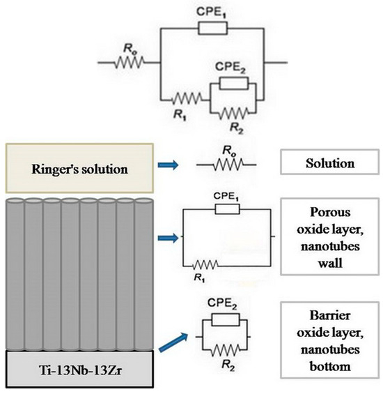
Figure 1.
The equivalent electrical circuit utilized for fitting the results.
In the mentioned EEC, Ro represents the resistance of the electrolyte, R2 and CPE2 constitute the resistance of the compact barrier layer and an element with a constant phase angle that directly depends on the frequency and which is often used instead of the compact barrier layer capacitance (C2) for inhomogeneous surfaces, while, R1 and CPE1 constitute the resistance of the porous layer and an element with a constant phase angle that directly depends on the frequency and which is used instead of the porous layer capacitance (C1). Also, R2 represents the resistance of the bottom of the nanotube, (Rnb), and R1 represents the resistance of the walls of the nanotube (Rnv).
The relationship between C and CPE can be represented by the following expressions [57]:
where n is a coefficient with values ranging from 0 to 1. The CPE is a resistor when n is 0. The Warburg impedance, which related to diffusion processes, has n values of 0.5, while complete capacitance C has n values of 1 [58]. By fitting experimentally obtained data, the values of resistance R, capacitance C, and coefficient n were determined for the natural oxide layer and nanostructured oxide layer created using the anodic oxidation process.
2.4. Scratch Test
A testing machine Nanoindenter G200 (Agilent Technologies, Santa Clara, CA, USA) with an indenter Berkovich-type diamond tip, was used to perform the tests by making a scratch on the surface of the Ti-13Nb-13Zr alloy before and after AO. The scratch’s length was 700 μm (with 50 μm/s) with the load progressively raised up to 40 mN (Figure 2). In this research, scratch testing was utilized to analyze the cross-profile of the topography and adhesion characterization of nanotubes surface formed after AO.
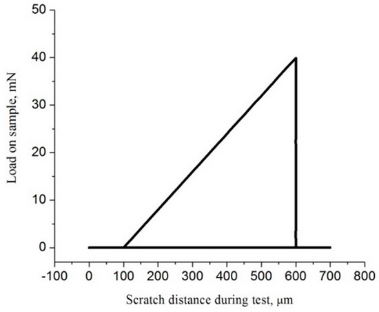
Figure 2.
Applied load during scratch test.
During this test, the normal force on the sample was controlled and increased. The scratch test procedure consists of 3 steps: First, a very small load was applied to detect the morphology of the same surface. Then, along the same scratch path, a normal force was applied that increases from the starting to the maximum scratch load. Finally, a very small force was used for the next profile, which measures the residual deformations in the indentations.
3. Results
3.1. Surface Morphology
The CG and UFG TNZ alloy was anodized in H3PO4 solution; the modified surfaces of titanium alloys were uniform compact oxide layers obtained at 25 V for 90 min, as shown in Figure 3 It can be observed that the oxide layer obtained on the CG surface was composed of nanotubes with larger and smaller diameters, but also larger and smaller wall thicknesses. This distribution of the dimensions of the formed nanotubes is known in the literature as a bimodal distribution [59]. The difference in the morphology of the nanotube oxide layer is thought to be due to the HPT procedure, which can change dissolution the rate of the oxides. Faghihi et al. [60] noticed that the nanotube oxide layer created on UFG cpTi is quite different from that on CG cpTi in chemical structure. They showed that the UFG structure has a weakening of the Ti bond in TiO2, which can induce a faster dissolution rate in the oxides during the formation of the nanotube oxide layer.
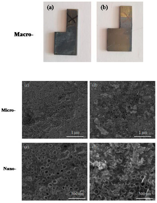
Figure 3.
Appearance of the samples and morphology of modified surface for (a,c,e) CG and (b,d,f) UFG Ti-13Nb-13Zr alloy after anodic oxidation.
Mean values of the nanotube dimensions with a standard deviation (SD) of 30 measures the function of the material structure, as shown in Figure 3.2a. Measurement of the nanotube dimension was performed using Image J software. The mean value of the nanotube diameter for the CG TNZ alloy is 76.44 nm, and the nanotube wall thickness is 20.34 nm (Figure 3c,e and Figure 4a). The oxide layer created on the UFG surface after anodic oxidation has a homogeneous structure. The mean value of the nanotube diameter for the UFG TNZ alloy is 90.17 nm, and the nanotube wall thickness is 19.57 nm (Figure 3d,f and Figure 4a).

Figure 4.
Comparison of (a) nanotube dimensions and (b) surface roughness for tested materials.
Figure 3 shows that the nanostructured surfaces consisted of larger and smaller nanotubes, but also larger and smaller wall thicknesses. This is confirmed by the large difference in the dimension measurements of the diameters of the nanotubes, ranging from 47.1 nm to 121.69 nm, for both alloys. The SD values indicate that a significant difference between the sizes of the nanotube diameters formed on the alloys under the same conditions of the electrochemical anodization process does not exist. The SD values of the diameter measurements are ±20.62 nm and ±16.27 nm for the za CG and UFG alloy, respectively, which indicates the better uniformity of the diameter for the nanotube oxide layer formed on the alloy after the HPT process. The values of the diameters of the nanotubes formed on the surface of the CG TNZ alloy range from 47.1 nm to 117.57 nm. On the other hand, the value of the diameter of the nanotubes formed on the surface of the UFG TNZ alloy ranges from 59.4 nm to 121.69 nm after anodic oxidation for 90 min. Observed in relation to the microstructure of the alloy, this difference in nanotube dimensions is greater on the surface of the coarse-grained alloy than on the surface of the fine-grained alloy. These results confirm the possibility of using the HPT procedure to obtain an adequate homogeneous nanotube oxide layer. Also, the SD values indicate that a significant difference between the sizes of the nanotube wall thicknesses formed on the alloys under the same conditions of the electrochemical anodization process does not exist. The SD values of the wall thickness measurements are ±2.46 nm and ±2.6 nm for the CG and UFG alloys, respectively. The values of the nanotube wall thickness formed on the surface of the CG TNZ alloy ranges from 14.94 nm to 22.91 nm. On the other hand, the value of the nanotube wall thickness formed on the surface of the UFG TNZ alloy ranges from 17.01 nm to 24.05 nm after anodic oxidation for 90 min.
UFG metallic materials processed by SPD methods have a high concentration of lattice imperfections, including vacancies, dislocations, and grain boundaries [61]. Those lattice defects are commonly related with a growth in electrical resistance and enhanced atom diffusivity, which can change electrochemical behavior, namely corrosion and anodic oxidation. The HPT process significantly refines the microstructure of titanium alloys, reducing the grain size to the ultrafine or nanocrystalline level (<100 nm). This UFG structure leads to more a uniform nanotube oxide layer, enhancing nanotube formation during anodic oxidation. It was shown that the large grain size of cpTi resulted in a less regular and less homogeneous nanotube oxide layer because the large grains were non-equiaxed [62]. In addition, in our previous study [48], we showed that, for a shorter anodic oxidation time, a more homogeneous nanotube oxide layer was obtained on the UFG TNZ than on the CG TNZ alloy. The presence of grain boundaries in UFG materials after HPT process provides additional diffusion pathways for ions during anodic oxidation. The results show that nanotube growth on the UFG surface induces larger-diameter nanotubes with more consistent and smaller wall thicknesses compared to nanotubes grown on the CG surface. A previous paper shows that the final dimensions (diameter, wall thickness, and length) of the nanotubes are influenced by both the anodic oxidation parameters and HPT process parameters [7,48,63]. In our previous papers [7,20,48,49], we have shown that the dimensions of the nanotubes and morphologies of the modified surface depend on the anodic oxidation time, and that, with increasing anodic oxidation duration, an increase in nanotube diameter is accompanied by a decrease in wall thickness. We have also shown that nanotubes become longer after processing the TNZ alloy using the HPT process [41]. Hu et al. [63] noticed that torsion strain in the HPT procedure had an influence on the dimension of the nanotubes. They showed that increasing turns from 1 to 10 led to longer nanotubes. Also, increasing turns from 1 to 10 led to increasing diameters of the nanotubes.
Figure 5 presents 2D AFM diagrams and linear profiles for the CG and UFG TNZ alloys before and after AO. A distinct variation in peak height is observed. The measured value of Ra for the non-anodized CG surface is 6.6 nm and the non-anodized UFG surface is 3.6 nm, while for the anodized CG surface it is 19.1 nm and for the anodized UFG surface it is 34.1 nm (Figure 4b). As a result of AFM measurement, the RMS (root mean squared) roughness of the anodized and non-anodized CG and UFG TNZ alloys was also obtained. RMS presents the standard deviation of the heights of the profile, and it is a more precise indicator of roughness because it includes the entire defined surface. As we present in our previous paper [7,64], the RMS value for the non-anodized CG TNZ was 2.36 nm and the anodized CG TNZ was 11.27 nm, while for the non-anodized UFG TNZ it was 4.52 and for anodized UFG TNZ it was 17.12 nm (Figure 4b). Results show that larger diameters of the nanotubes lead to higher surface roughness values due to the more pronounced surface topography. On the other hand, thicker walls of the nanotubes can lead to a denser and rougher structure. The homogeneity of the nanotube oxide layer formed using anodic oxidation significantly affects roughness consistency across the surface. A uniform, highly ordered nanotube oxide layer results in consistent roughness, favorable for biomedical applications like improved cell adhesion. In contrast, an inhomogeneous nanotube oxide layer can create micro-rough areas or defects, leading to unpredictable surface behavior and decreased biocompatibility. Although HPT is not a surface modification treatment, it can influence surface roughness indirectly. Results show that the HPT process can slightly change roughness, probably due to intense shear strain. However, polishing or surface modification treatments after the HPT process are often applied to tailor the roughness of the surface for specific applications. Moreover, the refined microstructure using the HPT process enhances the uniformity of the nanotube oxide layer, promoting the formation of a more homogeneous nanotube oxide layer, which can also help control the roughness of the surface more precisely.
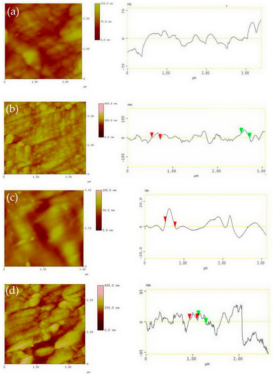
Figure 5.
Two-dimensional AFM images and linear profile for non-anodized surface of CG TNZ (a), anodized surface of CG TNZ (b), non-anodized surface of UFG TNZ (c) and anodized surface of UFG TNZ (d).
3.2. XRD Analyses
Figure 6 presents an XRD diagram of an oxide layer created on the tested materials. Figure 6 shows that no anatase and/or rutile phases appeared on the surfaces of the CG TNZ and UFG TNZ alloys, independent of the alloy’s microstructure, after anodic oxidation in an 1M H3PO4 + NaF electrolyte for 90 min. Results of the XRD method show that the amorphous nanotube oxide layer is created on the CG and UFG’s surface after AO in defined solutions.
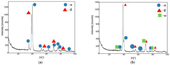
Figure 6.
XRD diagram of nanotube oxide layer created on the (a) CG and (b) UFG Ti-13Nb-13Zr alloys after anodic oxidation.
Conventional XRD has limited surface sensitivity when applied to the analysis of thin films on the surfaces of metallic materials, such as the oxide layers of nanotubes. Namely, the penetration depth of the radiation can be greater than the thickness of the nanotube oxide layer. This means that XRD could collect signals from both the nanotube surface and the substrate surface. In this case, Grazing Incidence XRD (GIXRD) is often applied. However, the literature indicates that GIXRD is often used for thin nanotube layers with thicknesses from 100 nm to 500 nm and less than 1000 nm, while conventional XRD is possible to use for thin nanotube layers with thicknesses higher than 1000 nm [65]. In our previous paper [41], we show that nanotube oxide layers formed on the CG and UFG Ti-13Nb-13Zr alloys are thicker than 1000 nm. Also, a previous study [55,66] successfully apply the conventional XRD method to analyze thin nanotube oxide layers formed on titanium alloys whose thicknesses ranged from 1250 to 2000 nm.
As is shown in the literature, the crystallization of titanium nanotubes occurs in the anatase phase at a temperature around 300 °C, while the rutile phase occurs at around 500 °C, with the dominated rutile phase of nanotubes occurring after annealing at 700 °C [67]. Also, the intensity of the anatase phase decreases with increasing applied voltage [68]. A previous study showed that the anatase phase of titanium nanotubes totally converted into the rutile phase after anodic oxidation at 180V [69]. An amorphous titanium nanotube oxide layer can provide good corrosion resistance due to their uniform defect-free structure, which can act as an effective barrier against ion transport and localized corrosion. Studies have shown that an amorphous titanium nanotube oxide layer can be chemically stable in physiological environments, especially in chloride-rich solutions like simulated body fluid [70,71]. On the other hand, crystalline structures lead to superior corrosion resistance. A rutile structure is more chemically stable and less reactive in simulated body fluid, while an anatase structure is less stable than the rutile structure, but still has good corrosion resistance. Saji et al. [55] studied and compared the corrosion behavior of a Ti-13Nb-13Zr alloy with a formed amorphous nanotube oxide layer and crystalline anatase nanotube oxide layer in Ringer’s solution. Their results showed that an amorphous nanotubes oxide layer shows better corrosion resistance than a crystalline anatase nanotube oxide layer. On the other hand, Saji et al. [66] showed that a crystalline nanoporous oxide layer has better corrosion resistance in Ringer’s solution than a crystalline nanotube oxide layer formed on Ti–35Nb–5Ta–7Zr. The crystalline anatase TiO2 layer is known for its superior hydrophilicity with a small contact angle [72], which promotes better protein adsorption and cell attachment—critical for osseointegration. In contrast, an amorphous TiO2 layer tends to be less hydrophilic, although surface treatments (e.g., UV irradiation or functionalization) can enhance its wettability [73].
3.3. Contact Angle
Contact angle images of the CG TNZ and UFG TNZ alloys before and after anodic oxidation are shown in Figure 7, while values of the contact angle are given in Table 1. The contact angle of the CG TNZ material was measured as 99.45°, while after anodic oxidation for 90 min, the contact angle of the CG TNZ material was decreased to 56.7°. The contact angle of the UFG TNZ material was measured as 67.3°, while after anodic oxidation for 90 min, the contact angle of the UFG TNZ material was decreasing to 40.9°. The values of the contact angle decreased in the following order: CG TNZ > UFG TNZ > CG TNZ after anodic oxidation, 90 min > UFG TNZ alloy after anodic oxidation, 90 min.
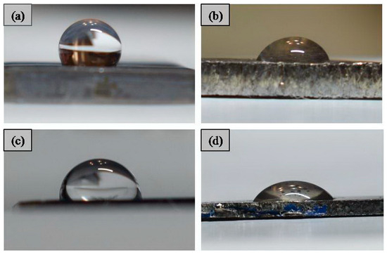
Figure 7.
Contact angle images of (a) CG TNZ, (b) CG TNZ after anodic oxidation, (c) UFG TNZ, and (d) UFG TNZ after anodic oxidation.

Table 1.
Comparison of roughness and contact angle for tested materials.
Results show that the contact angle decreases after anodic oxidation of CG TNZ and UFG TNZ, giving the surfaces of the materials a more hydrophilic character. Also, the contact angle decreases after the HPT process of the CG TNZ alloy. The results show that the synergistic effect of the HPT treatment and anodic oxidation leads to the lowest values of the contact angle, i.e., the highest hydrophilicity of the UFG TNZ alloy. Table 1 presents a comparison of the contact angles and roughness of the tested materials. Results show that increasing the roughness of the surface after anodic oxidation, at the same time, leads to a decrease in the value of the contact angle. The increasing roughness of the surface leads to an increase in the region that the solution can contact—in other words, it increases wettability of the surface. Also, it is known that, after the anodic oxidation of materials, the hydroxyl groups are formed and lead to increasing wettability [74]. Decreasing the contact angle means increasing the hydrophilicity of the titanium alloys [74], while a previous study found that the hydrophobic surface has a water contact angle higher than 65° [75]. It has been shown that the hydrophilicity of the surface of the metallic implant significantly affects the absorption of proteins, macromolecules, and bacteria, the interaction of hard and soft tissue with the surface of the implant, as well as the degree of osseointegration in in vivo studies [76]. For instance, Zhang et al. [77] studied the biological behavior of a Ti-(0–25 wt.%) Nb alloy and found that the contact angle influenced cell proliferation in a biocompatibility test. A previous study showed that the surface modification parameters of metallic biomaterials affect not only the morphology, roughness, and topography of the surface, but also the contact angle [75]. Kovaci et al. [74] investigated the influence of the anodic oxidation time on the contact angle of the cpTi, Ti-45 Nb, and Ti-6Al-4V surfaces. The results showed that, for all three materials, the contact angle decreased as the anodizing time increased.
3.4. Corrosion Resistance
The electrochemical impedance spectrum for the UFG and CG TNZ alloys, before and after anodic oxidation, is shown using Nyquist (Figure 8) and Bode (Figure 9) charts. All of the tested materials have the properties of corrosion stability, where it can be seen, based on the shape of the diagram and size of the semicircle diameter, that the CG TNZ, after anodic oxidation, has the best corrosion resistance of the nanotube oxide layer (Figure 8a). The Bode diagram has two time constants that describe the two oxide layers.
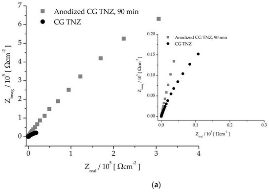
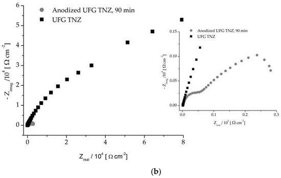
Figure 8.
Nyquist diagram of non-anodized and anodized CG TNZ (a) and UFG TNZ (b) alloy.
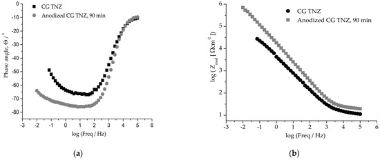
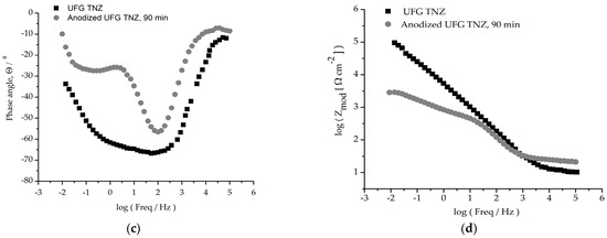
Figure 9.
Graphic representation of Bode diagrams (a,c) of phase angles and (b,d) moduli for CG TNZ and UFG TNZ alloys before and after anodic oxidation.
As can be seen in Figure 9b,d, an impedance magnitude around 105 Ωcm2 achieved in the low-frequency region indicates good corrosion resistance, while a value in the order of magnitude around 103 Ωcm2 for UFG TNZ, after anodic oxidation, indicates a drop in corrosion stability. For all materials, Zmod values in the order of 101 Ωcm2 in the frequency range of 0–100 kHz and phase angles close to 0° were achieved, which indicates the significant thickness of the outer porous layer [78]. In the Bode phase angle diagram, Figure 9a,c, wide peaks for CG TNZ after anodic oxidation and the UFG TNZ alloy indicate better their corrosion stability compared to their counterparts, CG TNZ and UFG TNZ, after anodic oxidation, respectively.
The obtained results for the tested materials using the EIS method are given in Table 2. It is evident that the outer porous layer (R1) exhibits lower corrosion resistance compared to the inner barrier layer (R2). Specifically, the resistance at the bottom of the nanotube (R2 or Rnb) is higher than that of the nanotube walls (R1 or Rnv). These findings indicate that the barrier layer demonstrates superior stability over the porous layer across all tested materials. The improvement in the corrosion stability of the CG TNZ alloy after anodic oxidation is clearly demonstrated by the results presented in Table 2. The lowest value of R2 in the Ringer solution was found for the UFG TNZ alloy. After anodic oxidation, R2 is 3.77 × 10³ Ω cm2, while the highest value of R2 in the Ringer solution was found for the CG TNZ alloy; after anodic oxidation, R2 is 1.42 × 10⁶ Ω cm2. The higher value of R2 indicates better stability of oxide layer, which indirectly indicates that the CG TNZ alloy, after AO, has superior corrosion stability than the UFG TNZ alloy after AO. Moreover, the time constant at medium frequencies, 0.1–1 Hz, becomes more pronounced with anodic oxidation for both the CG and UFG alloys, which confirms the creation of a compact barrier layer located at the base of the nanotube.
Table 2.
Electrochemical impedance spectroscopy results of CG and UFG TNZ alloys before and after anodic oxidation.
According to the presented equation, the thickness of the oxide film increases with a decrease in CPE [79]:
where ε0 is the electrical permittivity of the vacuum (8.854 × 10⁻¹⁴ Fcm−1), ε represents the dielectric constant of the film, S denotes the surface area, and h corresponds to the thickness of the oxide film.
The surface of the UFG TNZ alloy exhibits a greater thickness of the nanotube oxide layer than that of the CG TNZ alloy. This is indicated based on the capacitance (CPE) value because the CPE value of nanotube oxide layer on the UFG TNZ is lower than the CPE value of the nanotube oxide layer on the CG TNZ. Also, results in our previous paper [42] indicate that the HPT process leads to the possibility of obtaining a greater thickness in the oxide layer, i.e., longer nanotubes, after the anodic oxidation process. On the other hand, the thickness of the oxide layer on the surface after anodic oxidation is greater than that formed on the surface before anodic oxidation for both materials. It was also shown that the capacitance (CPE) of the nanotube oxide layer is lower than the capacitance of the naturally formed oxide layer. The coefficient n takes on values in the interval 0.65–0.86, as can be seen in Table 2.
Hence, the results of the EIS measurements verify the results of the potentiodynamic polarization measurement, which was presented in our previous paper [20]. Both methods show that the corrosion stability of oxide layer stability was higher on the CG TNZ after anodic oxidation and UFG TNZ alloy compared to their counterparts, CG TNZ and UFG TNZ, after anodic oxidation, respectively. The results show that forming a nanotube oxide layer on the surface of the CG TNZ alloy enhances its corrosion stability compared to the alloy before anodic oxidation. On the other hand, there is a drop in the corrosion stability of the UFG TNZ alloy after anodic oxidation. The morphology of the nanostructured oxide layer affects the corrosion stability of the material. The results show that increasing the nanotube diameter from 76.44 nm to 90.17 nm in the morphology of the nanotube oxide layer led to a decrease in corrosion resistance, i.e., a decrease in the inner barrier layer resistance value, R2, from 1.42 × 10⁶ Ω cm2 to a R2 value of 3.77 × 10³ Ω cm2. This results in an increase in the dimensions of the nanotube diameter, which leads to a decrease in corrosion resistance, as is already known in the literature [80,81]. Guo et al. [80] states in their review that the oxide layer with nanotubes with diameters ranging from 22 nm to 59 nm lead to an increase in corrosion resistance, while an increase in diameter to about 86 nm leads to a decrease in corrosion resistance. Also, Ossowska et al. [81] showed that a nanotube with a larger diameter (about 100 nm) had significantly worse corrosion resistance compared to a nanotube with a smaller diameter (about 60 nm). This is attributed to the large intra-tubular cavities that increased the contact area of the electrolyte and nanotube interface. Also, the numerous and larger channels between the nanotubes may allow for the electrolyte to penetrate the protective oxide layer, resulting in a corrosion reaction between the surface and the electrolyte ions [48]. On the surface of the CG TNZ alloy, after anodic oxidation, compact nanotubes without channels between them are formed, Figure 3a, which affected the enhancement in corrosion stability compared to the CG TNZ. Conversely, the development of a nanostructured oxide layer on the surface of the UFG TNZ leads to a drop in corrosion resistance because the morphology of the nanotube oxide layer is characterized by more space between nanotubes (Figure 3b). Measurement of the inter-tubular spacing was performed using Image-J software (version 1.54, NIH, Rockville Pike Bethesda, MD, USA). The mean space between nanotubes, with a standard deviation (SD) of 15 measurements as a function of material structure, is shown in Figure 4a. The mean space between nanotube values, calculated from 15 measurements, are 30.26 nm for the CG TNZ alloy and 55.71 nm for the UFG TNZ alloy, while SD values are ±4.13 nm and ±7.95, respectively.
Usually, titanium alloys with modified surfaces have higher corrosion resistances compared to the substrate [82,83]. It was shown that surfaces with a hybrid morphology composed of nanotubes and nanopores have higher corrosion protection than the morphology with nanotubes only [50]. Modifying the surface with nanopores or nanotubes on the TNZ alloy led to equivalent corrosion resistance when compared to other titanium alloys [50]. Many papers discuss the impact of modified surface morphology on corrosion stability and show that surfaces of titanium alloys with irregular morphology and, in some cases, voids can lead to decreases in corrosion resistance [50]. Jang et al. [51] showed that Ti-Nb alloys before and after anodic oxidation have good corrosion resistance and when, due to the irregular morphology of the nanotube oxide layer, the corrosion resistance was lower after anodization. Campanell et al. [52] noticed that anodic oxidation, with parameters of 40 V and 6 h or 20 V and 1h for a Ti-Mo alloy did not increase corrosion resistance, but did not significantly decrease corrosion resistance either. In our earlier study [48], the corrosion behavior and stability of the UFG and CG alloys, both before and after anodic oxidation, were examined in artificial saliva. It was found that the UFG TNZ alloy exhibited the best corrosion stability after undergoing anodic oxidation for 90 min. In the current study, corrosion stability was evaluated in Ringer’s solution, where the UFG TNZ alloy after anodic oxidation showed lower corrosion resistance compared to the CG TNZ alloy treated the same way. This variation in corrosion stability is attributed to the high concentration of chloride ions in Ringer’s solution, which are known to cause corrosion damage on the surfaces of titanium alloys [84]. Previous research indicates that UFG titanium alloys exhibit different corrosion behaviors in simulated body fluid versus artificial saliva [85]. Specifically, the UFG titanium alloy demonstrates better corrosion resistance in artificial saliva than in simulated body fluid. Also, it is well established that the microstructure of metallic materials greatly impacts their corrosion behavior. UFG materials contain a higher density of grain boundaries, which can serve as anodic sites. Consequently, a greater grain boundary density might be expected to reduce corrosion resistance [86]. However, contrary to this assumption, numerous studies have demonstrated that UFG titanium-based materials exhibit good corrosion stability due to their uniform grain distribution [87,88]. On the other hand, some research has found that grain refinement either did not enhance corrosion resistance or had no significant effect on the corrosion behavior of these materials [85,89]. From the literature review, it can be concluded that grain size significantly influences the corrosion resistance of titanium-based materials, while both the processing method and the electrolyte used also play crucial roles in determining corrosion stability. In order to determine the more precise effect of Ringer’s solution on the corrosion stability of CG and UFG TNZ alloys before and after anodic oxidation, future experiments will include tests of these materials immersed in Ringer’s solution for different time intervals, as well as tests of corrosion stability using the potentiodynamic polarization and electrochemical impedance spectroscopy methods.
3.5. Scratch Test
Figure 10 presents the profile along the cross-section of the scratched surface of CG TNZ and UFG TNZ after anodic oxidation for 90 min. As can be seen, the cross-section of the scratch is composed of two regions, groove area (GA) and pile-up areas (PA1, PA2) (show in Figure 10 in black and gray colors), while summation of PA1 and PA2 presents material remove area (MRA), Figure 10.
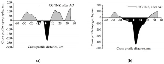
Figure 10.
The profile of scratch cross-section of the (a) CG TNZ and (b) UFG TNZ surface after anodic oxidation.
In cases when PA is larger, the dominant mechanism for removing materials is plowing; on the other hand, when GA is larger, the dominant mechanism for removing materials is shearing [90]. In cases when is radius of scratch indenter is large, material deforms plastically without formation of the material fragment; this is case when the depth or thickness of the material fragment is small. When the thickness of the material fragment exceeds limit values, formation of the material fragment, as well as the material’s removal mechanism, is shearing-dominant. Many previous studies defined parameters such as “Pile up ratio” and “Material removal area” to characterize the mechanisms of scratch testing metallic materials, and defined the criteria for the method of removing material [90] as follows: (1) PA1 + PA2 = GA = 0; pile-up ratio = ∞; dominant mechanism: rubbing, (2) PA1 + PA2 > GA; pile-up ratio > 1; dominant mechanism: plowing, (3) PA1 + PA2 = GA 0; pile-up ratio = 1; dominant mechanism: elastic-plastic transition, (4) PA1 + PA2 < GA; pile-up ratio < 1; dominant mechanism: shearing (plastic flow). The profiles of the scratch cross-sections for both materials show that PA is lower than GA, which indicated that the dominant mechanism for removing materials and forming material fragments during the scratch test is shearing (Figure 10). Also, the profile of the scratch cross-section for CG TNZ, after anodic oxidation, shows that the groove (scratch) depth is 223 nm, while the groove (scratch) width is about 17.5 μm (Figure 10a). The profile of the scratch cross-section for UFG TNZ, after anodic oxidation, shows that the groove (scratch) depth is 436 nm, while the groove (scratch) width is about 37.5 μm (Figure 10b). Wear can be evaluated based on the width and depth of the scratches. In most cases, scratch width is used to monitor wear progression, whereas scratch depth or material volume loss is more critical in applications requiring high wear resistance [91]. The values of scratch width and scratch depth depend on the scratch test conditions, i.e., the applied force, shape and radius of the indenter tip. For example, it has been shown that with the applied force increasing, the values of scratch width and depth increase too [92]. Also, it has been shown that increasing the indenter tip radius from 25 μm to 200 μm led to an increase in values of scratch width, while the values of scratch depth remain unchanged [92]. From Figure 11, it is noted that the scratch width is less for CG TNZ, while depth for CG TNZ, the surfaces are almost two times smaller than for UFG TNZ surfaces in the same test conditions. These results indirectly signify that the CG TNZ alloy after anodic oxidation could be more wear-resistant than the UFG TNZ alloy after anodic oxidation.
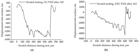
Figure 11.
Scratch test curve of (a) CG TNZ and (b) UFG TNZ surfaces after anodic oxidation.
Figure 11 presents the scratch test curve for the CG TNZ and UFG TNZ surfaces after anodic oxidation. In the case of the UFG TNZ surface, the slope of the scratch curve decreases with increasing displacement into the surface (when the mass of the nanotubes layer increased) (Figure 11). As can be seen, in the first and latter stages of the scratch, both curves indicate reapplication to the applied load. The slope of the scratch curves is relatively stiff (along scratch distance), indicating a slim possibility to annul the applied load. These facts indicate that the failure of the nanotube oxide layer occurred along the length of the scratch.
Scratch test curves show three regions, the ductile region, transition region (brittle-ductile transition) and brittle region, while large fluctuations appear at the beginning of region change. According to the literature [92], the appearance and changes in the diagram, as well as the surface morphology characteristics of the scratch, depend on the normal loading rate, indenter, and direction of the indenter, but it indicates that the above-mentioned three regions comprise every scratch test curve. Figure 12 presents the morphology characteristics of the scratch and damage to the oxide layer after the scratch test for CG TNZ and UFG TNZ surfaces after AO. Figure 12a–c present the whole scratch, some part of the scratch, and the final part of the scratch obtained on the CG TNZ surface after anodic oxidation. As can be seen, the scratch exists with a visible lateral accumulation of oxide layer material on both sides of the scratch’s edge. Also, at the final part of the scratch, accumulation of the material exists. On the other hand, Figure 12d,e, presents the whole scratch and some part of the scratch obtained on the UFG TNZ surface after anodic oxidation. As can be seen, with the progress of the scratching, both sides of the scratch show cracks and pieces of the fracture with much smaller or larger fragments of material (shown with red arrows). A previous paper showed that damaged to the oxide layer on the titanium-based surfaces is possible, but the adhesion of the coating is sustainable [93,94,95,96,97]. Zielenski et al. [93] noticed that the nanotube oxide layer created on the Ti-13Nb-13Zr alloy has a delamination mechanism associated with the brittle fracturing. Durdu et al. [94] created a nanotube oxide layer on a titanium alloy using anodic oxidation with different voltages and showed that increasing the voltage led to the increasing adhesion of the nanotube oxide layer. Sarraf et al. [95] researched the adhesion of the nanotube oxide layer created on the Ti-6Al-4V. They showed that adhesion increased after annealing. Hu et al. [96] showed that forming the homogeneous nanotube oxide layers after the HPT process led to improvements in their adhesion. Dikova et al. [97] showed that a higher roughness of the surface of titanium-based materials led to delamination of the smaller areas of the nanotube oxide layer after scratch-testing. The results of our study show that damage to the nanotube oxide layer occurs, but the magnification of the SEM image shows that the nanotubes are still adhesively stable at the very edges of the scratch (Figure 12e).
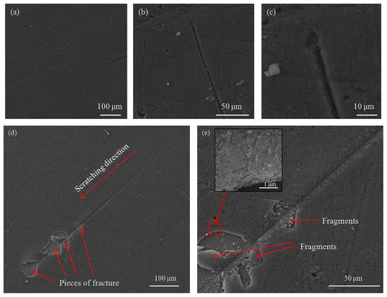
Figure 12.
Damage to the nanotube oxide layer formed on (a–c) CG and (d,e) UFG Ti-13Nb-13Zr alloy after scratch test.
Critical load (Lc) is used for the characterization of the adhesion strength of the coating of the materials. Lc denotes the moment of separation of the nanotube oxide layer from the metallic substrate. The literature shows that values of Lc depend on the thickness, hardness, and load-carrying capacity of the coating. Also, it was shown that methods such as microscopic evaluation are suitable for determining the value of the critical load [98]. Figure 2 shows a linear increase in load from 0 to 40 mN over a scratch length of about 700 μm, and this mode is typical for a progressive scratch test, where critical forces can be accurately read. A uniform increase in force enables the detection of multiple stages of damage to the coating. Based on Figure 2, the scratch-test curve in Figure 11b, and SEM images in Figure 12d,e, for the nanotube oxide layer formed on the UFG TNZ alloy, it can be seen that the beginning of the initial damage (Lc1) is in the form of a micro-crack (Figure 12d,e), and the first visible sharp jump on the scratch test curve (Figure 11b) is at about 436.36 μm, which is at the applied force of about 26.85 mN. Furthermore, it is visible that the cohesive peeling and crowning (Lc2) of the nanotube oxide layer occurs at 487.87 μm, or at a force of 30.94 mN. Also, local separation of the layer is present at both of the above-mentioned loads, while larger separation of the nanotube oxide layer is similar to a complete adhesion fracture (Lc3), and a sharp jump on the scratch test curve, as well as a break in the load, are visible near the value of 590–600 μm, i.e., for a force value of approximately 39.8 mN. On the other hand, for the nanotube oxide layer formed on CG TNZ, based on the scratch test curve in Figure 11a and the representation of the linear load during the scratch test, Figure 2, it can be seen that the first significant break in the nanotube oxide layer occurs at 226.15 μm, which corresponds to a force of 9.99 mN. This phenomenon in Figure 11a can indicate the initial micro-deformation and the appearance of the first cracks (Lc1) in the nanotubes. Furthermore, a pronounced drop and instability in the signal was recorded at around 302.4 μm, which corresponds to a force of 15.94 mN; this phenomenon can be associated with the beginning of peeling and cohesive failure (Lc2). Finally, a sharp jump in the diagram near 590–600 μm, which corresponds to a force of about 39.15 mN, can indicate the complete break of the coating (Lc3). These results indicate that the critical forces are lower in the CG TNZ alloy than in the UFG TNZ alloy, which means that the nanotube oxide layer shows weaker adhesion and scratch resistance when it is formed on a coarse-grained material. In addition, the nanotube oxide layer with a higher thickness showed better adhesion and resistance to scratching. The thickness of the nanotube oxide layer (the length of the nanotubes) has a significant influence on scratch resistance and adhesion behavior in scratch testing. The thickness of the nanotube oxide layer has a double effect on the mechanical responses in the scratch test. On the one hand, thicker layers with poorer adhesion yield easily at low loads, while, on the other hand, thicker layers with good adhesion improve resistance by achieving greater elasticity and better load distribution [95,96,97,98]. A small number of studies were carried out on the adhesion strength of a nanotube oxide layer formed on the titanium-based materials. Hu et al. [99] showed that the nanotube oxide layer formed on the UFG Ti–6Al–4V alloy obtained using the HPT process had enhanced adhesion strength. Adhesion strengths of the nanotube oxide layer on CG Ti-6Al-4V and UFG Ti-6Al-4V were 18.4 ± 2.2 mN and 26.1 ± 1.3, respectively. Durdu et al. [100] showed that scratching resistance and Lc values for the oxide layer formed on the Ti-6Al-4V alloy increased with increasing oxide layer thickness. Additionally, Sarraf et al. [95] showed that, after thermal annealing at 500 °C, the failure point in a scratch test increased from 862 mN to 1814 mN, indicating increased adhesion and resistance, which is highly dependent on changes in the properties of the oxide layer, such as thickness and microstructure.
4. Conclusions
Surface modification of titanium alloys through anodic oxidation has been shown to be an efficient technique for enhancing the properties required for biomedical applications. The results of this study demonstrate that anodic oxidation could improve corrosion stability, hydrophilicity, and roughness. The nanotube oxide layer was fabricated on the CG and UFG Ti-13Nb-13Zr alloys’ surface by the anodic oxidation method in an F-containing H3PO4 electrolyte for 90 min. Nanotube surfaces were more homogenous on the UFG surface than the ones produced on the CG surface. The surface roughness and diameters of the nanotubes notably grew after the HPT process on the Ti-13Nb-13Z alloy, while the nanotubes’ wall thickness decreased. Thus, the nanotube oxide layer fabricated on the CG surface consisted of nanotubes with larger and smaller diameters, but also larger and smaller wall thicknesses, as a randomly bimodal distribution of nanotubes dimensions. On the UFG surface, a nanotube oxide layer was fabricated with a more homogenous distribution of nanotubes dimensions, but with more spaces between nanotubes. These spaces between nanotubes in the morphology formed on the UFG surface led to a drop in corrosion resistance in the Ringer solution. Thus, anodic oxidation and the resulting morphology led to an increase in the corrosion stability of the CG TNZ, while the UFG TNZ alloy experienced a drop in corrosion resistance. The resistance of the barrier layer, obtained in this study, and corrosion current density values, obtained in our previous paper [20], indicate that the tested materials had adequate corrosion behavior for biomedical applications. The average contact angle values of the nanotube surfaces were approximately measured between 56.7° and 99.5°. Thus, this indicated that both the CG and UFG surfaces with nanotubes had a hydrophilic character. The scratch test showed that the nanotube oxide layer was damaged, but was still connected to the UFG Ti-13Nb-13Zr substrate, which indicated a strong interaction between the nanotube oxide layer and substrate and the good adhesion of the nanotubes. The synergistic effects of the HPT process and anodic oxidation offer significant potential for enhancing the surface characteristics of the Ti-13Nb-13Zr alloy, which are essential for its successful use in biomedical applications. Future research will continue to explore the optimization parameters of these processes to further improve the performance of the Ti-13Nb-13Zr alloy.
Author Contributions
Conceptualization, D.R.M.; Methodology, D.R.M., B.I.M., J.B.B. and V.R.D.; Validation, B.I.M., J.B.B. and V.R.D.; Formal analysis, D.R.M.; Investigation, D.R.M., B.I.M., J.B.B. and V.R.D.; Writing—original draft, D.R.M. and V.R.D.; Writing—review & editing, B.I.M., J.B.B. and V.R.D.; Visualization, B.I.M., J.B.B. and V.R.D.; Supervision, B.I.M., J.B.B. and V.R.D. All authors have read and agreed to the published version of the manuscript.
Funding
This research was funded by Ministry of Science and Technological Development and Innovation of the Republic of Serbia grant number [451-03-47/2025-01/200135 and 451-03-47/2025-01/200287].
Data Availability Statement
The original contributions presented in this study are included in the article. Further inquiries can be directed to the corresponding authors.
Acknowledgments
The authors acknowledge the help and constructive comments of Marko Rakin from the Faculty of Technology and Metallurgy, University of Belgrade, Serbia, during the research, and the help of Anton Hohenwarter from the Department of Materials Science, Montanuniversitat Leoben, Austria, for preparing UFG samples.
Conflicts of Interest
The authors declare no conflict of interest.
References
- Abd-Elaziem, W.; Darwish, M.A.; Hamada, A.; Daoush, W.M. Titanium-Based alloys and composites for orthopedic implants Applications: A comprehensive review. Mater. Des. 2024, 241, 112850. [Google Scholar] [CrossRef]
- Marin, E.; Lanzutti, A. Biomedical Applications of Titanium Alloys: A Comprehensive Review. Materials 2024, 17, 114. [Google Scholar] [CrossRef]
- Baltatut, M.S.; Tugui, C.A.; Perju, M.C.; Benchea, M.; Spataru, M.C.; Sandu, A.V.; Vizurean, P. Biocompatible Titanium Alloys used in Medical Applications. Rev. Chim. 2019, 70, 1302–1306. [Google Scholar] [CrossRef]
- Hoppe, V.; Szymczyk-Ziółkowska, P.; Rusinska, M.; Dybała, B.; Poradowski, D.; Janeczek, M. Assessment of Mechanical, Chemical, and Biological Properties of Ti-Nb-Zr Alloy for Medical Applications. Materials 2021, 14, 126. [Google Scholar] [CrossRef]
- Sypniewska, J.; Szkodo, M.; Majkowska-Marzec, B.; Mielewczyk-Gryń, A.D. Exploring the composition and corrosion resistance in hybrid-modified Ti13Nb13Zr alloy. MRS Commun. 2024, 14, 1439–1445. [Google Scholar] [CrossRef]
- Vasilescu, C.; Drob, S.; Osiceanu, P.; Drob, P.; Moreno, J.; Preda, S.; Ivanescu, S.; Vasilescu, E. Surface analysis, microstructural, mechanical and electrochemical properties of new Ti-15Ta-5Zr alloy. Met. Mater. Int. 2015, 21, 242–250. [Google Scholar] [CrossRef]
- Mihajlović, D.; Rakin, M.; Hohenwarter, A.; Veljović, D.; Kojić, V.; Djokić, V. The Effect of the Nanostructured Surface Modification on the Morphology and Biocompatibility of Ultrafine-Grained Titanium Alloy for Medical Application. In Mechanical Engineering in Biomedical Application: Biomaterials, Implant Design, Bio-3D Printing, Computational, Tissue & Biofluid Mechanics; Srivastava, J.P., Kozak, D., Ranjan, V., Kumar, P., Kumar, R., Tayal, S., Eds.; Wiley-Scrivener Publishing LLC: Austin, TX, USA, 2024; pp. 121–150. [Google Scholar] [CrossRef]
- Lee, T.; Lee, S.; Kim, I.S.; Moon, Y.H.; Kim, H.S.; Park, C.H. Breaking the limit of Young’s modulus in low-cost Ti–Nb–Zr alloy for biomedical implant applications. J. Alloys Compd. 2020, 828, 154401. [Google Scholar] [CrossRef]
- Klinge, L.; Kluy, L.; Spiegel, C.; Siemers, C.; Groche, P.; Coraça-Huber, D. Nanostructured Ti-13Nb-13Zr alloy for implant application—Material scientific, technological, and biological aspects. Front Bioeng. Biotechnol. 2023, 11, 1255947. [Google Scholar] [CrossRef] [PubMed]
- Lee, T. Variation in Mechanical Properties of Ti-13Nb-13Zr Depending on Annealing Temperature. Appl. Sci. 2020, 10, 7896. [Google Scholar] [CrossRef]
- Ke, Z.; Yi, C.; Zhang, L.; He, Z.Y.; Tan, J.; Jiang, Y.H. Characterization of a new Ti-13Nb-13Zr-10Cu alloy with enhanced antibacterial activity for biomedical applications. Mater. Lett. 2019, 253, 335–338. [Google Scholar] [CrossRef]
- Takadoum, J. Review on Corrosion, Tribocorrosion and Osseointegration of Titanium Alloys as Biomaterials. Corros. Mater. Degrad. 2023, 4, 644–658. [Google Scholar] [CrossRef]
- Mace, A.O.; Kurtz, M.A.; Gilbert, J.L. Fretting and Fretting Corrosion Behavior of Additively Manufactured Ti-6Al-4V and Ti-Nb-Zr Alloys in Air and Physiological Solutions. J. Funct. Biomater. 2024, 15, 38. [Google Scholar] [CrossRef]
- Kumar, P.; Mahobia, G.S.; Mandal, S.; Singh, V.; Chattopadhyay, K. Enhanced corrosion resistance of the surface modified Ti-13Nb-13Zr alloy by ultrasonic shot peening. Corros. Sci. 2021, 189, 109597. [Google Scholar] [CrossRef]
- Kong, Q.; Lai, X.; An, X.; Feng, W.; Lu, C.; Wu, J.; Wu, C.; Wu, L.; Wang, Q. Characterization and corrosion behaviour of Ti-13Nb-13Zr alloy prepared by mechanical alloying and spark plasma sintering. Mater. Today Commun. 2020, 23, 101130. [Google Scholar] [CrossRef]
- Fan, X.; Fan, W. Preparation and biological activity study of Ti13Nb13Zr surface nanotubes. Biosurf. Biotribol. 2024, 10, 2405–4518. [Google Scholar] [CrossRef]
- Hoppe, V.; Szymczyk-Ziółkowska, P.; Rusińska, M. Study of cytotoxic activity of Ti–13Nb–13Zr medical alloy with different surface finishing techniques. J. Mater. Sci. 2021, 56, 17747–17767. [Google Scholar] [CrossRef]
- Xu, J.; Hu, J.; Liu, S.; Wang, J.; Ma, Z.; Guo, S.; Li, M.; Zhang, E. Effect of Anodic Oxidation on Antibacterial Properties and Biocompatibility of Ti-13Nb-13Zr-3Cu for Biomedical Application. Adv. Eng. Mater. 2024, 26, 1438–1656. [Google Scholar] [CrossRef]
- Tan, A.; Pingguan-Murphy, B.; Ahmad, R.; Akbar, S. Review of titania nanotubes: Fabrication and cellular response. Ceram. Int. 2012, 38, 4421–4435. [Google Scholar] [CrossRef]
- Barjaktarević, D.; Medjo, B.; Štefane, P.; Gubeljak, N.; Cvijović-Alagić, I.; Djokić, V.; Rakin, M. Tensile and Corrosion Properties of Anodized Ultrafine-Grained Ti–13Nb–13Zr Biomedical Alloy Obtained by High-Pressure Torsion. Met. Mater. Int. 2021, 27, 3325–3341. [Google Scholar] [CrossRef]
- Nikolova, M.P.; Apostolova, M.D. Advances in Multifunctional Bioactive Coatings for Metallic Bone Implants. Materials 2023, 16, 183. [Google Scholar] [CrossRef]
- Jazdzewska, M.; Kwidzinska, D.B.; Seyda, W.; Fydrych, D.; Zielinski, A. Mechanical Properties and Residual Stress Measurements of Grade IV Titanium and Ti-6Al-4V and Ti-13Nb-13Zr Titanium Alloys after Laser Treatment. Materials 2021, 14, 6316. [Google Scholar] [CrossRef]
- Jiang, P.; Zhang, Z.; Hu, R.; Shi, B.; Zhang, L.; Huang, Q.; Yang, Y.; Tang, P.; Lin, C. Advanced surface engineering of titanium materials for biomedical applications: From static modification to dynamic responsive regulation. Bioact. Mater. 2023, 27, 15–57. [Google Scholar] [CrossRef]
- Nicholson, W.J. Titanium Alloys for Dental Implants: A Review. Prosthesis 2020, 2, 100–116. [Google Scholar] [CrossRef]
- Barjaktarević, D.; Cvijović-Alagić, I.; Dimić, I.; Đokić, V.; Rakin, M. Anodization of Ti-based materials for biomedical applications: A review. Metall. Mater. Eng. 2016, 22, 129–143. [Google Scholar] [CrossRef] [PubMed]
- Barjaktarević, D.; Đokić, V.; Rakin, M. Nanotubular oxide layer formed on the Ti-based implants surfaces-application and possible damages: A review. Metall. Mater. Eng. 2018, 24, 243–259. [Google Scholar] [CrossRef] [PubMed]
- Manovah, D.T.; Ranjan, P.D.; Wilson, P.; Sagayaraj, P.; Mathews, T. A critical review on the variations in anodization parameters toward microstructural formation of TiO2 nanotubes. Electrochem. Sci. Adv. 2021, 2, 2698–5977. [Google Scholar] [CrossRef]
- Ribeiro, B.; Offoiach, R.; Rahimi, E.; Salatin, E.; Lekka, M.; Fedrizzi, L. On Growth and Morphology of TiO2 Nanotubes on Ti6Al4V by Anodic Oxidation in Ethylene Glycol Electrolyte: Influence of Microstructure and Anodization Parameters. Materials 2021, 14, 2540. [Google Scholar] [CrossRef]
- Osak, P.; Skwarek, S.; Łukowiec, D.; Przeliorz, G.; Łosiewicz, B. Preparation and Characterization of Oxide Nanotubes on Titanium Surface for Use in Controlled Drug Release Systems. Materials 2024, 17, 3753. [Google Scholar] [CrossRef] [PubMed]
- Hanna, S.; Adelia, K.; Ludek, H.; Saldan, I.; Celko, L.; Edgar, B.M.; Macak, J.M. Anodic TiO2 Nanotubes on 3D-Printed Titanium Meshes for Photocatalytic Applications. Nano Lett. 2021, 21, 8701–8706. [Google Scholar] [CrossRef]
- Kim, J.; Lee, H.; Jang, T.S.; Kim, D.; Yoon, C.B.; Han, G.; Kim, H.E.; Jung, H.D. Characterization of Titanium Surface Modification Strategies for Osseointegration Enhancement. Metals 2021, 11, 618. [Google Scholar] [CrossRef]
- Kumar, P.S.; Grandhi, V.V.; Gupta, V. The Effects of Titanium Implant Surface Topography on Osseointegration: Literature Review. JMIR Biomed. Eng. 2019, 4, e13237. [Google Scholar] [CrossRef]
- Sepúlveda, M.; Capek, J.; Baishya, K.; Rodriguez-Pereira, J.; Bacova, J.; Jelinkova, S.; Zazpe, R.; Sopha, H.; Rousar, T.; Macak, J.M. Enhancement of biocompatibility of anodic nanotube structures on biomedical Ti–6Al–4V alloy via ultrathin TiO2 coatings. Front Bioeng. Biotechnol. 2024, 12, 1515810. [Google Scholar] [CrossRef]
- Fuentes, E.; Alves, S.; López-Ortega, A.; Mendizabal, L.; Sáenz, V.V. Advanced Surface Treatments on Titanium and Titanium Alloys Focused on Electrochemical and Physical Technologies for Biomedical Applications. In Biomaterial-Supported Tissue Reconstruction or Regeneration; Barbeck, M., Jung, O., Smeets, R., Koržinskas, T., Eds.; In Tech: Rijeka, Croatian, 2019. [Google Scholar] [CrossRef]
- Zhong, M.H.; Liu, Y.; Wei, K.X. Microstructure, Wettability and Corrosion Behaviors of TiO2 Nanotube Arrays on Ti-13Nb-13Zr Alloy. J. Mater. Eng. Perform. 2025, 34, 1–9. [Google Scholar] [CrossRef]
- Oliveira, N.T.C.; Ferreira, E.A.; Duarte, L.T.; Biaggio, S.R.; Rocha-Filho, R.C.; Bocchi, N. Corrosion resistance of anodic oxides on the Ti–50Zr and Ti–13Nb–13Zr alloys. Electrochim. Acta 2006, 51, 2068–2075. [Google Scholar] [CrossRef]
- Vasilescu, C.; Drob, S.I.; Neacsu, E.I.; Rosca, M.J.C. Surface analysis and corrosion resistance of a new titanium base alloy in simulated body fluids. Corros. Sci. 2012, 65, 431–440. [Google Scholar] [CrossRef]
- Jiang, H. Enhancement of Titanium Alloy Corrosion Resistance via Anodic Oxidation Treatment. J. Electrochem. Sci. 2018, 13, 3888–3896. [Google Scholar] [CrossRef]
- Sowa, M.; Piotrowska, M.; Widziołek, M.; Dercz, G.; Tylko, G. Bioactivity of coatings formed on Ti–13Nb–13Zr alloy using plasma electrolytic oxidation. Mater. Sci. Eng. C 2015, 49, 159–173. [Google Scholar] [CrossRef]
- Valiev, Z.R.; Straumal, B.; Langdon, T.G. Using Severe Plastic Deformation to Produce Nanostructured Materials with Superior Properties. Annu. Rev. Mater. Res. 2022, 52, 357–382. [Google Scholar] [CrossRef]
- Mihajlović, D.; Medjo, B.; Cvijović-Alagić, I.; Djokić, V. Coarse to Fine: The Role of Severe Plastic Deformation in Advancing Titanium-Based Medical Implants—A Comprehensive Review. J. Wuhan Univ. Technol. Mater Sci. Ed. 2025, 4, 295–306. [Google Scholar] [CrossRef]
- Edalati, K. Review of Advances in High-Pressure Torsion of Titanium and Ti-Based Materials (Alloys, Intermetallics, Oxides and High-Entropy Compounds). Mater. Trans. 2025, 66, 464–478. [Google Scholar] [CrossRef]
- Xu, Q.H.; Wei, X.K.; Wei, W.; Dzugan, J.; Alexandrov, V.I.; An, L.X.; Wang, D.D.; Liu, K.X.; Daniel, M.K.; Hradil, D. Microstructure and mechanical properties evolution of Ti-13Nb-13Zr alloy processed by ECAP-Conform and rotary swaging. J. Alloys Compd. 2023, 969, 172351. [Google Scholar] [CrossRef]
- Agarwal, K.M.; Tyagi, R.K.; Singhal, A.; Bhatia, D. Effect of ECAP on the mechanical properties of titanium and its alloys for biomedical applications. Mater. Sci. Energy Technol. 2020, 3, 921–927. [Google Scholar] [CrossRef]
- Jorge, M.A.; Roche, J.V.; Pérez, A.G.D.; Valiev, Z.R. Nanostructuring Ti-Alloys by HPT: Phase Transformation, Mechanical and Corrosion Properties, and Bioactivation. Mater. Trans. 2023, 64, 1306–1316. [Google Scholar] [CrossRef]
- Miyamoto, H. Corrosion of Ultrafine Grained Materials by Severe Plastic Deformation, an Overview. Mater. Trans. 2016, 57, 559–572. [Google Scholar] [CrossRef]
- Barjaktarević, D.; Dimić, I.; Cvijović-Alagić, I.; Veljović, Đ.; Rakin, M. Corrosion resistance of high pressure torsion obtained commercially pure titanium in acidic solution. Tech. Gaz. 2017, 24, 1689–1695. [Google Scholar] [CrossRef]
- Barjaktarević, D.; Djokić, V.; Bajat, J.; Dimić, I.; Cvijović-Alagić, I.; Rakin, M. The influence of the surface nanostructured modification on the corrosion resistance of the ultrafine-grained Ti–13Nb–13Zr alloy in artificial saliva. Theor. Appl. Fract. Mech. 2019, 103, 102307. [Google Scholar] [CrossRef]
- Barjaktarević, D.; Međo, B.; Đokić, V.; Rakin, M. Morphology and nanomechanical properties of the ultrafine-grained Ti-13Nb-13Zr alloy surface obtained using electrochemical anodization. In Experimental and Numerical Investigations in Materials Science and Engineering; Mitrović, N., Mladenović, G., Mitrović, A., Eds.; Springer: Cham, Switzerland, 2021; pp. 123–141. [Google Scholar] [CrossRef]
- Pérez, D.A.G.; Alberto Junior, M.J.; Asato, H.G.; Lepretre, J.C.; Virginie Roche, V.; Bolfarini, C.; Botta, W.J. Surface anodization of the biphasic Ti13Nb13Zr biocompatible alloy: Influence of phases on the formation of TiO2 nanostructures. J. Alloys Compd. 2019, 796, 93–102. [Google Scholar] [CrossRef]
- Jang, H.; Choe, H.C.; Ko, Y.M.; Brantley, W.A. Electrochemical characteristicsof nanotubes formed on TieNb alloys. Thin Solid Film. 2009, 517, 5038–5043. [Google Scholar] [CrossRef]
- Campanelli, C.; Oliveira, N.T.C.; da Silva, P.S.C.P.; Bolfarini, C.; Palmieri, A.; Cura, F.; Carinci, F.; Motheo, A.J. Fatigue resistance, electrochemical corrosion and biological response of Ti-15Mo with surface modified by amorphous TiO2 nanotubes layer. J. Biomed. Mater. Res. Part B Appl. Biomater. 2019, 107, 86–96. [Google Scholar] [CrossRef]
- Brammer, K.; Oh, S.; Cobb, C.; Bjursten, L.; Heyde, H.; Jin, S. Improved bone-forming functionality on diameter-controlled TiO2 nanotube surface. Acta Biomaterialia 2009, 5, 3215–3223. [Google Scholar] [CrossRef]
- Dimić, I.; Cvijović-Alagić, I.; Volker, B.; Hohenwarter, A.; Pippan, R.; Veljović, Đ.; Rakin, M.; Bugarski, B. Microstructure and Metalic Ion Release of Pure Titanium and Ti-13Nb-13Zr Alloy Processed by High Pressure Torsion. Mater. Des. 2016, 91, 340–347. [Google Scholar] [CrossRef]
- Saji, V.; Choe, C.H. Electrochemical corrosion behaviour of nanotubular Ti–13Nb–13Zr alloy in Ringer’s solution. Corros. Sci. 2009, 51, 1658–1663. [Google Scholar] [CrossRef]
- Ratner, B.; Brunette, D.; Tengvall, P.; Textor, M.; Thomsen, P. Titanium in Medicine; Springer: New York, NY, USA, 2001. [Google Scholar]
- Jianwen, Z.; Henglei, Q.; Jianchao, Y.; Zhi, Z.; Tingting, C.; Changliang, L.; Li-ang, Q.; Ying, S.; Wenbo, O.; Jian, Y. The application and prospect of titanium materials in marine engineering equipments. Mar. Appl. 2008, 12, 2268–2270. [Google Scholar]
- Askeland, D. The Science and Engineering of Materials; PWS-KENT: Boston, MA, USA, 1989. [Google Scholar]
- Ossowska, A.; Sobieszczyk, S.; Supernak, M.; Zielinski, A. Morphology and properties of nanotubular oxide layer on the Ti–13Zr–13Nb alloy. Surf. Coat. Technol. 2014, 258, 1239–1248. [Google Scholar] [CrossRef]
- Faghihi, S.; Zhilyaev, A.P.; Szpunar, J.A.; Azari, F.; Vali, H.; Tabrizian, M. Nanostructuring a titanium material by high-pressure torsion improves pre-osteoblast attachment. Adv. Mater. 2007, 19, 1069–1073. [Google Scholar] [CrossRef]
- Valiev, R.Z.; Estrin, Y.; Horita, Z.; Langdon, T.G.; Zehetbauer, M.J.; Zhu, Y.T. Producing bulk ultrafine-grained materials by severe plastic deformation. J. Mater. Sci. 2006, 58, 33–39. [Google Scholar] [CrossRef]
- Ferreira, C.P.; Gonçalves, M.C.; Caram, R.; Bertazzoli, R.; Rodrigues, C.A. Effects of substrate microstructure on the formation of oriented oxide nanotube arrays on Ti and Ti alloys. Appl. Surf. Sci. (Part B) 2013, 285, 226–234. [Google Scholar] [CrossRef]
- Hu, N.; Gaoa, N.; Chen, Y.; Starink, J.M. Achieving homogeneous anodic TiO2 nanotube layers through grain refinement of the titanium substrate. Mater. Des. 2016, 110, 346–353. [Google Scholar] [CrossRef]
- Barjaktarević, D.; Đokić, V.; Stevanović, S.; Rakin, M. Influence of the electrochemical anodization on the surface roughness of Ti-13Nb-13Zr medical alloy. In Proceedings of the 10th International Conference on Tribology-Balkantrib ’20, Beograd, Serbia, 20–22 May 2021; pp. 59–62. [Google Scholar]
- Burns, E.W.; Pergolesi, D.; Schmidt, T.J.; Lippert, T.; Daramalla, V. Systematic Material Study Reveals TiNb2O7 as a Model Wide-Bandgap Photoanode Material for Solar Water Splitting. Chem. Eur. J. 2020, 26, 7065–7073. [Google Scholar] [CrossRef]
- Saji, V.; Choe, C.H.; Brantley, A.W. An electrochemical study on self-ordered nanoporous and nanotubular oxide on Ti–35Nb–5Ta–7Zr alloy for biomedical applications. Acta Biomater. 2009, 5, 2303–2310. [Google Scholar] [CrossRef]
- Viswanathan, S.; Saji, S.V.; Choe, C.H.; Brantley, A.W. Nanotubular oxide layer formation on Ti–13Nb–13Zr alloyas a function of applied potential. J. Mater. Sci. 2009, 44, 3975–3982. [Google Scholar] [CrossRef]
- Simka, W.; Krzakała, A.; Masełbas, M.; Dercz, G.; Szade, J.; Winiarski, A.; Michalska, J. Formation of bioactive coatings on Ti–13Nb–13Zr alloy for hard tissue implants. RSC Adv. 2013, 3, 11195–11204. [Google Scholar] [CrossRef]
- Cuia, X.; Kimb, H.M.; Kawashitac, M.; Wanga, L.; Xiong, T.; Kokubod, T.; Nakamurae, T. Preparation of bioactive titania films on titanium metal via anodic oxidation. Dent. Mater. 2009, 25, 80–86. [Google Scholar] [CrossRef]
- Tuba Yetim, T. Corrosion Behavior of Ag-doped TiO2 Coatings on Commercially Pure Titanium in Simulated Body Fluid Solution. J. Bionic Eng. 2016, 13, 397–405. [Google Scholar] [CrossRef]
- Minhas, B.; Dino, S.; Zuo, Y.; Qian, H.; Zhao, X. Improvement of Corrosion Resistance of TiO2 Layers in Strong Acidic Solutions by Anodizing and Thermal Oxidation Treatment. Materials 2021, 14, 1188. [Google Scholar] [CrossRef]
- Zeng, Q.; Liu, K. Surface characterization and superhydrophilic properties of TiO2 nanopores prepared by multi-step anodizing process. Appl. Surf. Sci. 2025, 690, 162617. [Google Scholar] [CrossRef]
- Terriza, A.; Díaz-Cuenca, A.; Yubero, F.; Barranco, A.; Gonzalez-Elipe, A.R.; Caballero, J.L.G.; Vilches, J.; Salido, M. Light induced hydrophilicity and osteoblast adhesion promotion on amorphous TiO2. J. Biomed. Mater. Res. Part A 2013, 101A, 1026–1035. [Google Scholar] [CrossRef]
- Kovacı, H.; Senela, K.; Acar, M.T.; Bozkurt, Y.B.; Çelik, A. Comparative investigation of structural, morphological, mechanical, tribological and electrochemical properties of TiO2 films formed on Cp-Ti, Ti6Al4V and Ti45Nb alloys. Surf. Coat. Technol. 2024, 487, 131024. [Google Scholar] [CrossRef]
- Strnad, G.; Chirila, N.; Petrovan, C.; Russu, O. Contact Angle Measurement on Medical Implant Titanium Based Biomaterials. Procedia Technol. 2016, 22, 946–953. [Google Scholar] [CrossRef]
- Gittens, R.A.; Scheideler, L.; Rupp, F.; Hyzy, S.L.; Geis-Gerstorfer, J.; Schwartz, Z.; Boyan, B.D. A review on the wettability of dental implant surfaces II: Biological and clinical aspects. Acta Biomater. 2014, 10, 2907–2918. [Google Scholar] [CrossRef]
- Zhang, Y.; Sun, D.; Cheng, J.; Tsoi, H.K.J.; Chen, J. Mechanical and biological properties of Ti (0–25 wt%) Nb alloys for biomedical implants application. Regen. Biomater. 2020, 7, 119–127. [Google Scholar] [CrossRef]
- Cvijović-Alagić, I. Damage and Fracture Resistance of Titanium Based Alloys for Medical Application. Ph.D. Thesis, Faculty of Technology and Metallurgy, University of Belgrade, Belgrade, Serbia, 2013. (In Serbian). [Google Scholar]
- Dimić, I.; Cvijović-Alagić, I.; Hohenwarter, A.; Pippan, R.; Kojić, V.; Bajat, J.; Rakin, M. Electrochemical and biocompatibility examinations of high-pressure torsion processed titanium and Ti–13Nb–13Zr alloy. J. Biomed. Mater. Res. B Appl. Biomater. 2017, 106, 1097–1107. [Google Scholar] [CrossRef]
- Guo, T.; Scimeca, J.-C.; Ivanovski, S.; Verron, E.; Gulati, K. Enhanced Corrosion Resistance and Local Therapy from Nano-Engineered Titanium Dental Implants. Pharmaceutics 2023, 15, 315. [Google Scholar] [CrossRef]
- Ossowska, A.; Zieliński, A.; Olive, J.-M.; Wojtowicz, A.; Szweda, P. Influence of Two-Stage Anodization on Properties of the Oxide Coatings on the Ti–13Nb–13Zr Alloy. Coatings 2020, 10, 707. [Google Scholar] [CrossRef]
- Rafieerad, A.R.; Bushroa, A.R.; Zalnezhad, E.; Sarraf, M.; Basirun, W.J.; Nasiri-Tabrizi, B.S. Microstructural development and corrosion behavior of self-organized TiO2 nanotubes coated on Ti-6Al-7Nb. Ceram. Int. 2015, 41, 10844–10855. [Google Scholar] [CrossRef]
- Sarraf, M.; Sukiman, N.L.; Bushroa, A.R.; Nasiri-Tabrizi, B.; Dabbagh, A.; Abu Kasim, N.H.; Basirun, W.J. In vitro bioactivity and corrosion resistance enhancement of Ti-6Al-4V by highly ordered TiO2 nanotube arrays. J. Aust. Ceram. Sociate 2018, 55, 187–200. [Google Scholar] [CrossRef]
- Prando, D.; Brenna, A.; Diamanti, M.; Beretta, S.; Bolzoni, F.; Ormellese, M.; Pedeferri, M. Corrosion of titanium: Part 1: Aggressive environments and main forms of degradation. Appl. Biomater. Funct. Mater. 2017, 15, e291–e302. [Google Scholar] [CrossRef]
- Nie, L.; Zheng, F.; Cheng, Y.; Wei, C.; Valiev, Z. In vitro corrosion and cytotoxicity on microcrystalline, nanocrystalline and amorphous NiTi alloy fabricated by high pressure torsion. Mater. Lett. 2010, 64, 983–986. [Google Scholar] [CrossRef]
- Sankar, M.; Gopal, V.; Alexander, R.; Manivasagam, G.; Ramalingam, M. Nanobiomaterials-Classification, Fabrication and Biomedical Applications; Wiley-VCH Verlag GmbH & Co: Weinheim, Germany, 2018. [Google Scholar]
- Janeček, M.; Čížek, J.; Stráský, J.; Václavová, K.; Hruška, P.; Polyakova, V.; Gatina, S.; Semenova, I. Microstructure evolution in solution treated Ti-15Mo alloy processed by high pressure torsion. Mater. Charact. 2014, 98, 233–240. [Google Scholar] [CrossRef]
- Lin, Z.; Wang, L.; Xue, X.; Lu, W.; Qin, J.; Zhang, D. Microstructure evolution and mechanical properties of a Ti–35Nb–3Zr–2Ta biomedical alloy processed by equal channel angular pressing (ECAP). Mater. Sci. Eng. C 2013, 33, 4551–4561. [Google Scholar] [CrossRef]
- Marnier, G.; Keller, C.; Noudem, J.; Hug, E. Functional properties of a spark plasma sintered ultrafine-grained 316L steel. Mater. Des. 2014, 63, 633–640. [Google Scholar] [CrossRef]
- Pratap, A.; Divse, V.; Saurav Goel, S.; Joshi, S.S. Understanding the surface generation mechanism during micro-scratching f Ti-6Al-4V. J. Manuf. Process. 2022, 82, 543–558. [Google Scholar] [CrossRef]
- Rajendhran, N.; Baets, P.; Huang, S.; Vleugels, J.; Sukumaran, J. Single-point scratch testing for understanding particle engagement in abrasion of multiphase materials. Wear 2021, 476, 203689. [Google Scholar] [CrossRef]
- Tang, K.; Ou, W.P.; Mao, C.; Liang, J.; Zhang, M.K.; Zhan, M.J.; Hu, Y.L. Material removal characteristics of single crystal 4H-SiC based on varied-load nanoscratch tests. Chines J. Mech. Eng. 2023, 36, 111. [Google Scholar] [CrossRef]
- Zielinski, A.; Antoniuk, P.; Krzysztofowicz, K. Nanotubular oxide layers and hydroxyapatite coatings on ‘Ti–13Zr–13Nb alloy. Surf. Eng. 2014, 30, 643–649. [Google Scholar] [CrossRef]
- Durdua, S.; Sancakb, M.; Yalcinb, E.; Ustac, M.; Akagunduzc, E.; Altinkoke, A. Surface characterization of TiO2 nanotube arrays produced on Ti-6Al-4V alloy by anodic oxidation. Surf. Coat. Technol. 2021, 428, 127903. [Google Scholar] [CrossRef]
- Sarraf, M.; Razak, B.A.; Crum, R.; Gamez, C.; Ramirez, B.; Abu Kasim, N.H.B.; Nasiri- Tabrizi, B.; Gupta, V.; Sukiman, N.L.; Basirun, W.J. Adhesion measurement of highly-ordered TiO2 nanotubes on Ti-6Al-4V alloy. Process. Appl. Ceram. 2017, 11, 311–321. [Google Scholar] [CrossRef]
- Hu, N.; Wu, Y.; Xie, L.; Yusuf, M.S.; Gao, N.; Starink, M.J.; Tong, L.; Chu, P.K.; Wang, H. Enhanced interfacial adhesion and osseointegration of anodic TiO2 nanotube arrays on ultra-fine-grained titanium and underlying mechanisms. Acta Biomater. 2020, 106, 360–375. [Google Scholar] [CrossRef] [PubMed]
- Dikova, A.; Nikolova, M.; Yankov, E. Adehsion analysis of titanium oxide nanocoating on titanium surface. Scientific proceedings XIII international congress. Mach. Technol. Mater. 2016, 2, 46–51. [Google Scholar]
- Azari, R.; Rezaie, R.H.; Khavandi, A. Effect of titanium dioxide intermediate layer on scratch and corrosion resistance of sol–gel-derived HA coating applied on Ti-6Al-4V substrate. Prog. Biomater. 2021, 10, 259–269. [Google Scholar] [CrossRef]
- Hu, N.; Liu, Y.; Zhao, M.; Wang, P.; Wu, G.; Hu, S.; Sun, J.; Wang, Y.; Zhang, Z.; Ma, L.; et al. Influence of the Intensity, Components, and Spreading of the Deqi Sensation on the Analgesic Effect of SP6 Needling in Primary Dysmenorrhea Patients: A Secondary Analysis of a Randomised Controlled Trial. Evid. Based Complement. Altern. Med. 2019, 384, 133985. [Google Scholar] [CrossRef] [PubMed]
- Durdu, S.; Usta, M. The tribological properties of bioceramic coatings produced on Ti6Al4V alloy by plasma electrolytic oxidation. Ceram. Int. 2014, 40, 3627–3635. [Google Scholar] [CrossRef]
Disclaimer/Publisher’s Note: The statements, opinions and data contained in all publications are solely those of the individual author(s) and contributor(s) and not of MDPI and/or the editor(s). MDPI and/or the editor(s) disclaim responsibility for any injury to people or property resulting from any ideas, methods, instructions or products referred to in the content. |
© 2025 by the authors. Licensee MDPI, Basel, Switzerland. This article is an open access article distributed under the terms and conditions of the Creative Commons Attribution (CC BY) license (https://creativecommons.org/licenses/by/4.0/).