Article

Dissimilar Resistance Spot Weld of Ni-Coated Aluminum to Ni-Coated Magnesium Using Cold Spray Coating Technology

Department of Mechanical & Mechatronics Engineering, University of Waterloo, 200 University Ave W, Waterloo, ON N2L 3G1, Canada
*
Author to whom correspondence should be addressed.
Metals 2025, 15(9), 940; https://doi.org/10.3390/met15090940
Submission received: 18 July 2025 / Revised: 15 August 2025 / Accepted: 19 August 2025 / Published: 24 August 2025

Abstract

Direct fusion welding of aluminum (Al) to magnesium (Mg) results in the formation of brittle intermetallic compounds (IMCs) that significantly restrict the application of these joints in structural applications. In this study, cold spray, a promising solid-state coating deposition technology, was employed to introduce a nickel (Ni) interlayer to facilitate joining of Al to Mg sheets by means of resistance spot welding (RSW). The ability of cold spraying to deposit metallic powder on the substrate without melting proves beneficial in mitigating the formation of the Al-Mg IMCs. The Ni-coated coupons were subsequently welded via resistance spot welding at optimized parameters: 27 kA for 15 cycles in two pulses with a 5-cycle inter-pulse delay. Scanning electron microscopy confirmed metallurgical bonding between the Al, Mg, and Ni coatings in the fusion zone. It is shown that the bonding between the three elements inhibits the formation of deleterious IMCs. Tensile shear testing showed joint strength exceeding 4.2 kN, highlighting the potential of the proposed cold spray RSW approach for dissimilar joining in structural applications.

1. Introduction

Cold spraying (CS) is a solid-state coating deposition process in which metal powder particles are accelerated at supersonic speeds towards a substrate. This technology was developed originally as a coating deposition method in the 1980s [1,2]. In this coating technique, a propulsion gas such as air, nitrogen, or helium is compressed to high temperature and pressure to accelerate the particles or the powders of raw materials to high speeds exceeding the speed of sound. Upon impact, the particles experience localized plastic deformation at the inter-particle and particle-substrate interfaces, and deposit onto the substrate by a combination of mechanical interlocking and metallurgical bonding. The formation of a cold spray coating depends largely on the kinetic energy of the particles prior to impact and not on the thermal energy. The particles used in cold spraying remain solid during the entire coating process.
The parameters which affect the coat quality are the size and the velocity of the particles. Reliable deposition via cold spraying requires exceeding the critical particle velocity [3,4,5,6,7]. In general, the critical velocity for adhesion depends on material type, particle size, and particle temperature during the spray process. Increasing the size of the particles and the temperature can reduce the critical velocity during the cold spray coating process [3,5,7,8]. The acceptable range of the powder size is between 10 and 100 μm in diameter in the cold spray process to ensure there is sufficient particle speed to exceed the critical velocity [6]. Accelerating particles outside of the size range is not beneficial and will reduce deposition efficiency considerably [9]. The effective particle size range that has frequently been used is 20 to 60 μm; however, with low-density materials such as Al and Zn, the useful particle size can increase up to 100 μm [6]. The flexibility of the cold spray coating process allows this technique to be utilized in many fields of application [10,11].
Cold spray technology presents a promising approach for enabling resistance spot welding (RSW) of dissimilar joints. Lara et al. [12] conducted significant research using CS to enhance RSW of Al/steel welds by comparing CS and Laser Powder Bed Fusion (LPBF) for coating 316L stainless steel interlayers. Their work demonstrated the benefits of using additively manufactured interlayers over conventional sheets, highlighting the advantage of CS due to its lower temperature operation. More recently, Szwajka et al. [13] investigated the application of copper and gold interlayers fabricated by cold spray to improve the RSW of Ti6Al4V titanium alloy and DP600 steel. Their study showed that the cold-sprayed interlayers effectively enhanced joint strength by suppressing the formation of brittle Ti–Fe intermetallic compounds and promoting more favorable microstructural transformations, which significantly increased the tensile-shear strength compared to joints without an interlayer. Additionally, Hagen et al. [14] employed CS to deposit a 316L stainless steel interlayer when welding AlSi10MnMg aluminum alloy to micro-alloyed steel, demonstrating that the interlayer successfully produced robust joints while reducing defects and softening in the heat-affected zone. Collectively, these studies underline the great potential of CS as an enabling technology for improving RSW of dissimilar material combinations. However, the application of CS coating in facilitating welding magnesium (Mg) to aluminum (Al) via resistance spot welding (RSW), alloys, and welding methods of interest in the automotive industry, for achieving weight reductions, remains unexplored.
Fusion welding of Mg to Al creates brittle intermetallic compounds (IMCs) such as Al12Mg17 and/or Al2Mg3, which deteriorate joint properties and may form cracks in the weld. Improved strength of Mg/Al joints can be achieved by controlling IMCs and/or by reducing their undesired effects [15]. One approach that has been used is placing interlayers between the sheets in order to avoid Al and Mg interactions, and thus inhibiting the formation of IMCs [15,16,17]. However, the strength of the joint will be dependent on the strength of the intermetallic compounds formed either at the Mg side or the Al side. Mg’s and Al’s melting points are 650 and 660 °C, respectively, whereas the Ni interlayer investigated here has a melting point of 1455 °C. Nickel and steel (melting point 1425–1540 °C) have been used as interlayers to restrict the mixing of Al and Mg to form IMCs, since the interlayer will remain as a solid barrier during welding [17,18]. Also, Ni has been adopted to promote the formation of Al-Ni and Mg-Ni IMCs, which are less brittle than Al-Mg IMCs. These factors make Ni-based interlayers a good candidate as a barrier interlayer with the RSW dissimilar joint Al/Mg.
The possibility of using a Ni-based interlayer in RSW of Al and Mg has been investigated by Penner et al. [17]. A pure Ni foil interlayer was used in an attempt to join AZ31B magnesium alloy to 5754 aluminum alloy. The results pointed out that pure Ni foil as an interlayer did not successfully provide a bonded intermetallic between Al and Mg sheets using the investigated welding parameters. The low heat input applied with a pure Ni interlayer led to failure of the Ni bonding in the Al to Mg joints as reported by Sun et al. [19], in a study where AZ31B magnesium alloy and 5754 aluminum alloy were joined with a pure Ni interlayer. However, in this case, a higher welding current was applied with the electrode tip on the Al side being smaller than the Mg side to promote more uniform heat generation. The weld fracture loads in this case reached about 5.1 kN when the welding current ranged from 32 to 36 kA. The Ni interlayer restricted the formation of Al-Mg IMC by staying unmelted while Al–Ni and Mg–Ni intermetallic layers were created at Al/Ni and Mg/Ni interfaces, respectively [19]. On the other hand, Penner et al. [17] showed that a gold-coated Ni interlayer can also achieve a successful bonding of the two material sheets and operate as a barrier to avoid Al-Mg IMC formation. Since the gold-coated nickel interlayer has a higher melting point than the Al and the Mg, it did not melt during welding. RSW joints produced an average load of 4.69 kN under a quasi-static lap-shear test, which is up to 90% of the strength obtained from similar AZ31B welds.
Other interlayer materials have also been considered as well. For example, Penner et al. [18] also placed a pure zinc foil and zinc-coated HSLA steel as interlayers in RSW of AZ31B Mg alloy to Al 5754 alloy. Al-Mg IMC was found when using pure zinc foil, resulting in poor joint strength with microhardness values in the nugget zone of 224–304 HV. However, the zinc-coated steel provided higher weld strength according to the AWS D17.2 standard [18], which reached up to 74% of the strength of similar AZ31B RSW joints, since the zinc-coated steel prevented the formation of Al-Mg IMCs [18]. According to Penner et al. [18], placing pure zinc foil as an interlayer did not enhance the strength of the Mg/Al RSW joint. Zhang et al. [16] suggested the thermo-compensated RSW process, which uses a zinc interlayer to weld AZ31B Mg alloy to AA5052-H12 Al alloy. In such a process, more heat may be generated at the weld area and specifically at the Al side. Placing a stainless-steel tape between the Al sheet and the electrode, which increases the melted metal and size of the nugget at the Al side, subsequently enhances the welded joint strength. The tensile-shear load resulting from this process was three times higher than that produced load by conventional RSW with the same interlayer. However, strengths achieved with the thermo-compensated RSW process with a zinc foil interlayer were low compared with the zinc-coated steel and Ni interlayers [16]. Sun et al. [20] used a Sn-coated steel interlayer in welding dissimilar joint AA5052 to AZ31 compared with Mg/Mg RSW joints. The strength of Al/Mg RSW joints with a Sn-coated steel interlayer was 88% of the strength of a similar Mg joint. Few performance studies of interlayer modified dissimilar joints have been performed, where Sun et al. [21] performed fatigue test for Al/Mg RSW with Sn-coated steel interlayer, and the results of the tests point out that the fatigue life of Al/Mg RSW joint has the same life as the Mg/Mg joints. Although there was a difference in the degradation rate until the final fatigue failure, where the Al/Mg has a faster degradation rate in the life range <105 than the Mg/Mg RSW joint. Table 1 summarizes and compares the strength of Al/Mg RSW joints that have been reported in earlier studies available in the literature using different interlayers.
To date, the cold spray coating process has not been used to enhance Al/Mg dissimilar RSW joints. However, cold spray has been considered for a lower energy welding method, the ultrasonic spot weld (USW) [24]. Panteli et al. [24,25] evaluated Al to Mg joining using USW and the effect of depositing a 50 to 100 μm thick layer of Al powder on the Mg substrate using the cold spray coating process prior to welding. The researchers found that strength can be improved to levels comparable with Mg-Mg joints when a cold spray interlayer is employed. In addition, the microstructure of the dissimilar Al to Mg USW joint containing a cold-sprayed layer was investigated in Panteli’s work [25]. The researchers found that the cold spray coating layer can significantly reduce the formation of the Al-Mg IMCs between the two sheets by 50% and increase the resulting fracture energy. Also, they found that there is an interaction between the Al-coated layer and the Mg surface after the welding process, which creates Al-Mg IMCs.
Hou et al. [26,27] adopted cold spray to apply a Ni coating layer on the Cu in order to improve the strength of dissimilar friction stir welded Cu/Al butt joints and to prevent undesirable IMCs. They reported an average tensile strength increase of 25%, from 152 MPa to 190 MPa, which was attributed to an improvement in the ductility of the joint by nearly 100%. Additionally, a notable drop in the thickness of the IMCs was observed, decreasing from 1.2 μm to around 200 nm. Kavian et al. [23] adopted another coating method for depositing three different distinct layers, Ni-TiO2, Ni, and Ni-Al2O3, which were electrodeposited individually on the Al in a lap shear joint configuration. The researchers reported that the addition of nano-sized TiO2 and Al2O3 helped reduce grain size in the weld zone, contributing to improved shear strength of the Al/Mg RSW joint. However, the maximum load that was obtained in this study was 520 N when Ni-Al2O3 was used as the interlayer. Dong et al. [28] placed a Ni foil interlayer with different thicknesses to explore the effect of the thickness of the Ni foil on the strength of the dissimilar Al/Mg friction stir-welded (FSW) butt joint. The study found that the maximum strength was achieved by placing 0.3 mm Ni foil, which increased the strength by 13.5% compared to the Al/Mg FSW joint without a Ni interlayer.
Despite the growing body of research exploring various interlayer materials and joining techniques for dissimilar Al/Mg welds, the review above highlights two critical gaps. First, there has been no investigation into the fatigue performance of cold-sprayed interlayers in RSW of Al/Mg joints. Second, the behavior of cold-sprayed Ni coatings under the unique thermal and mechanical conditions of the RSW process remains unexplored, as prior studies have focused on alternative welding methods with differing thermal cycles. To address these gaps, the present study aims to enable the welding of dissimilar Al/Mg sheets via RSW using cold spray coating technology and to systematically evaluate the performance, structural behavior, and utility of cold-sprayed Ni interlayers in this context. Figure 1 displays schematically the research in the current study.

2. Materials and Methods

2.1. The Materials

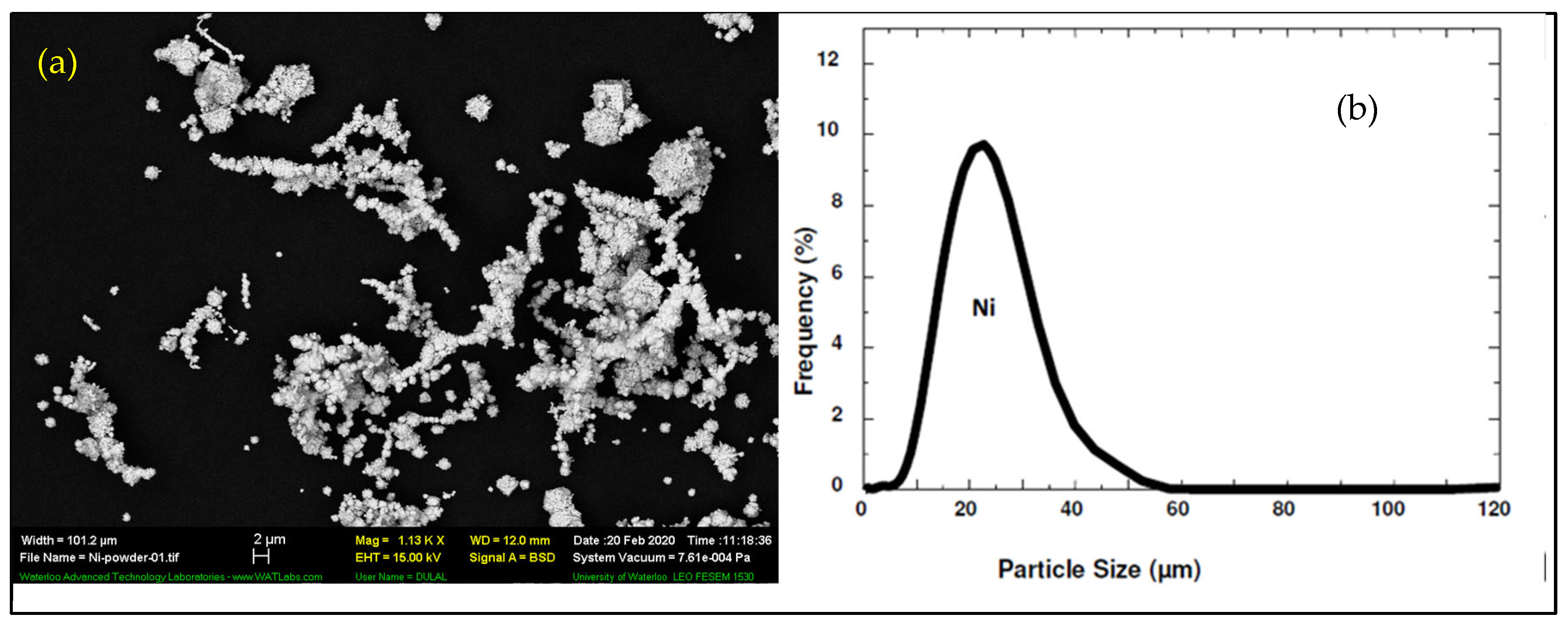
Ni powder was deposited on the Al AA6022-T4 sheet and the Mg AZ31B-O sheet as substrates. The Ni particles acquired from Centerline Ltd, Windsor, ON, Canada, with morphology and size distributions shown in Figure 2, were used in this coating process. The specifications of Ni powder, which is obtained by the supplier of the powder that the Ni powder has an irregular shape and the average particle size is 5–45 μm [29].
Two sets of samples have been prepared. First, the Al sheet dimensions are 25 × 25 × 1.5 mm, and the Mg sheet dimensions are 25 × 25 × 2 mm, which were prepared to optimize the welding parameters. Another set of samples were prepared for the monotonic test with the Al sheet dimensions of 100 × 39 × 1.5 mm, and the Mg sheet dimensions of 100 × 39 × 2 mm. The chemical compositions of the Al and Mg sheets are shown in Table 2.

2.2. Methods

A commercial low-pressure cold spray system (Centerline SST Series P, Windsor, ON, Canada) was used to deposit pure Ni powders. The substrate surfaces were prepared by sandblasting and cleaned with acetone right before the coating process. The AA6022-T4 and AZ31B-O Mg substrates were coated with Ni powder using the parameters summarized in Table 3.
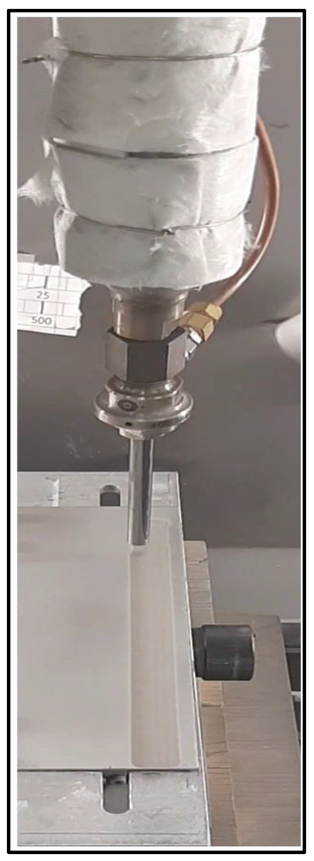
The SST Series P by Centerline Ltd. Windsor, ON, Canada is a low-pressure cold spray system specifically designed for depositing soft metal coatings such as aluminum, copper, nickel, zinc, and tin directly and onsite. At operating, pressures can be set between 100 and 250 psi (7–17.2 bar) and temperatures up to 550 °C. The process is housed in a cabinet with automated spray gun configurations as shown in Figure 3, easily maneuvered with UltiLife™ nozzles. Also, the system is equipped with a non-pressurized feeder that delivers consistent powder flow (up to ~120 g/min). The system includes an optional calibration kit for precise temperature and pressure control, which makes this device ideal for lightweight, site-specific coatings.
Coated coupons were studied for the coat deposition quality, thickness, and surface roughness. To make sure the substrate was totally covered with a uniform Ni layer, a caliper was used to measure the thickness right after the coating process, and then optical microscopy was used on metallographic samples to measure the thickness of the coating layer before and after the welding process. Surface roughness was measured using a Nanovea M1 surface roughness measurement device. The device operates using optical profilometry, specifically white light interferometry or chromatic confocal technology, for a contactless scan of the surface to generate high-resolution 3D surface topography. Its principle relies on detecting variations in reflected light intensity or interference patterns to measure surface height differences with nanometer precision.
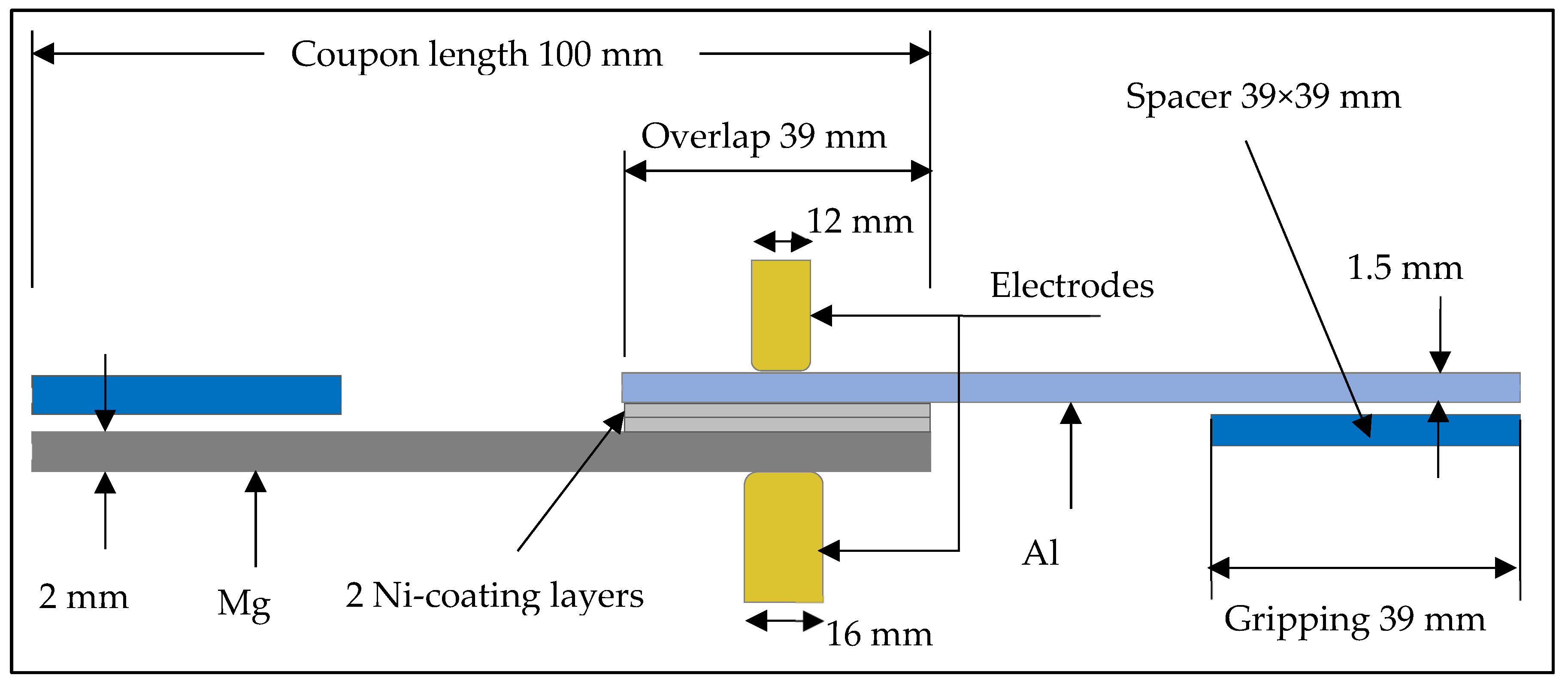
A Medium-Frequency Direct Current (MFDC) spot welder was used to weld the coupons. The maximum current of MFDC is 60 kA, and the maximum electrode force is 25 kN. The weld process was performed on the Ni-coated Al and Ni-coated Mg coupons. For all samples through the welding process, the electrode force was 4 kN, the water flow rate was 7 L/min, and the electrode diameters were 16 mm on the Mg side and 12 mm on the Al side. All samples with the different welding currents and times successfully bonded together or produced a sound weld.
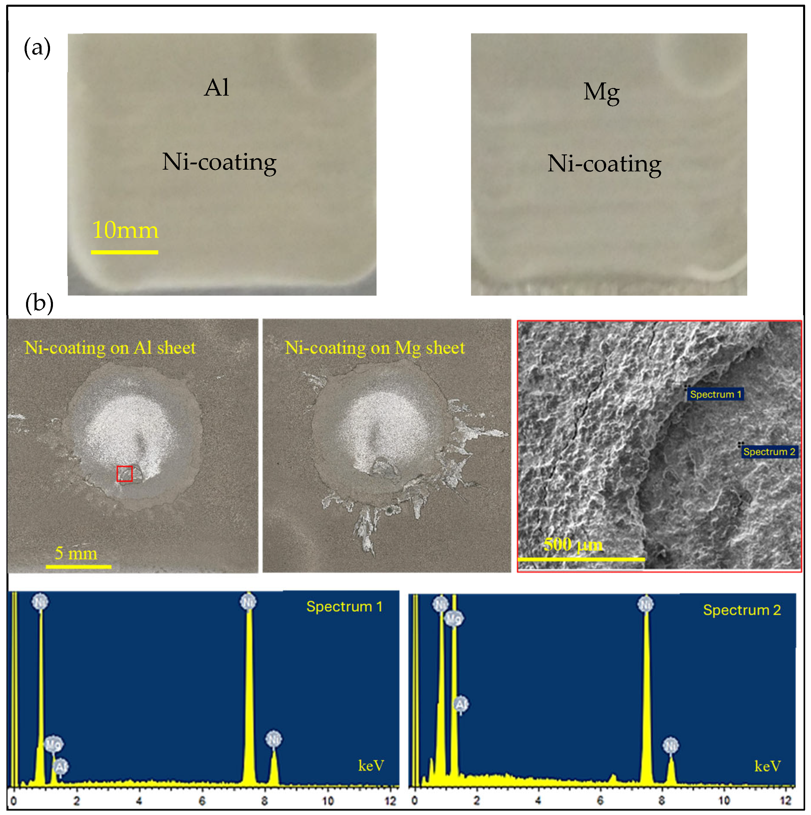
An 810 MTS frame with a load capacity of up to 50 kN was used to perform the tensile test. The dimensions of the Al coupons are 39 × 100 × 1.5 mm, and the Mg coupons are 39 × 100 × 2 mm. Therefore, the length of the Al to Mg lap shear samples, which were used in the monotonic test after the welding, is 161 mm. All the dimensions of the lap-shear configuration are schematically shown in Figure 4. The samples were coated with Ni as shown in Figure 3 and Figure 5. All quasi-static tests were performed in load control mode with a loading rate of 0.5 mm/min.
Scanning Electron Microscopy (SEM), LEO 1530 microscope, and FEI Quanta FEG 250 ESEM microscope (with EDX) were employed to study the microstructure characterization of the welding area and to find out how the Ni-coating at the welding zone restricts IMCs formation, in addition to studying the fracture surface and failure behavior.

3. Results and Discussion

3.1. Cold Spray Coating

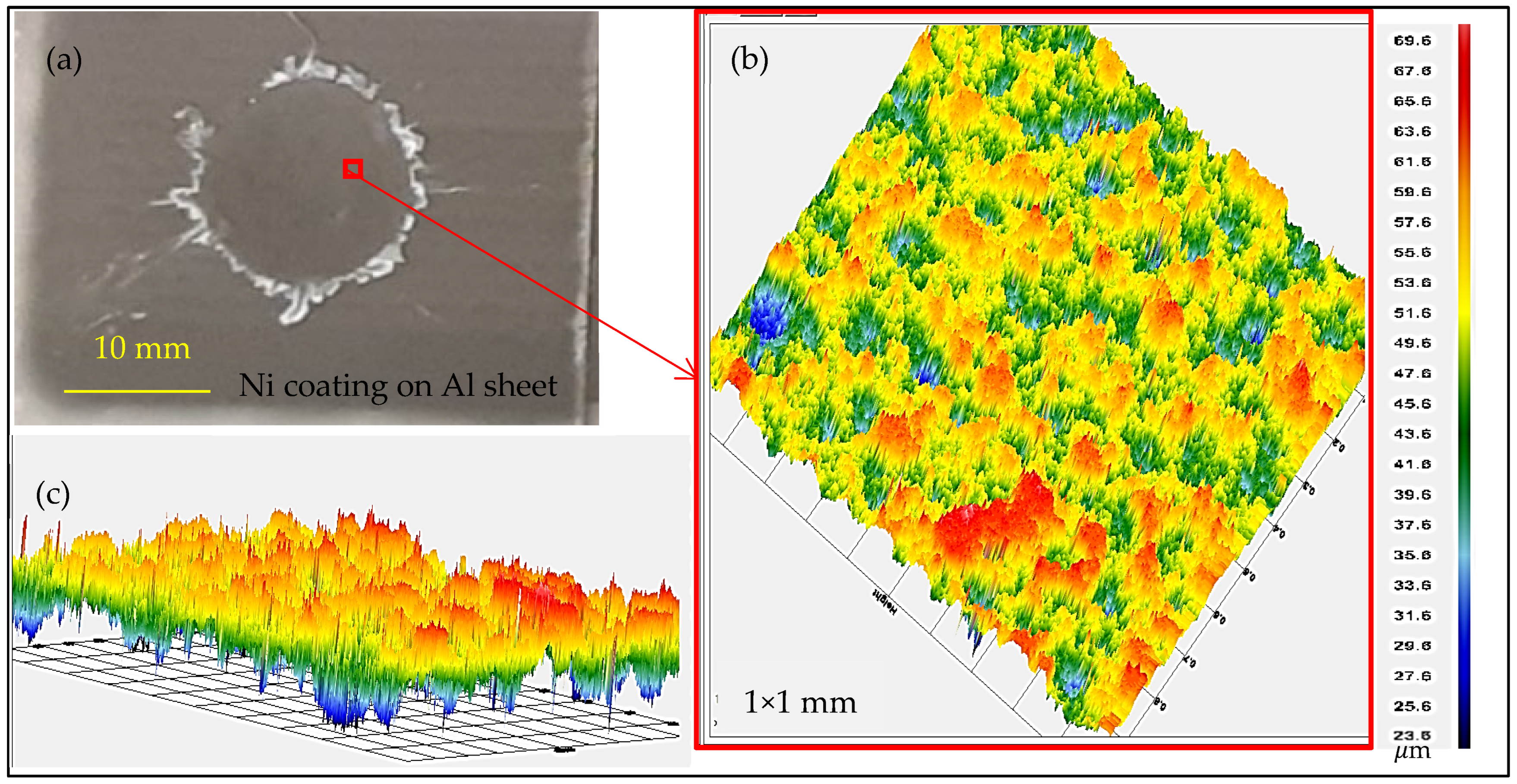
The average thickness of the Ni coating layer obtained with the parameters in Table 3 was around 110 μm on each substrate, for a total Ni coating thickness of around 220 μm between the two coupons. The thickness of the Ni-coating was measured by optical microscopy in order to obtain the range between the peaks and valleys, which gives a range of 70–110 μm. This range of thickness is matched well with surface roughness results from the Ni-coating that has been examined using a Nanovea M1, which ranges from ~40 μm to 25 and 65 μm, in the 3D scanning images. The 3D scans of the coating surfaces are shown in Figure 6.

3.2. Resistance Spot Weld

Figure 7 shows the effect of different welding parameters on the extent of weld nugget formation. Welding parameters have been optimized as follows: initially with one pulse, coated samples have been welded with five levels of welding currents—26, 26.5, 27, 27.5, and 28 kA, and three different welding times—25, 30, and 35 cycles. However, to determine which parameters are best suited to weld, the weld nugget sizes for different levels of welding current and welding times were measured. Following trials with a single pulse, it was found that weld nugget sizes and strengths were insufficient for overlap testing, and subsequently, two pulses with 15 to 20 cycles each have been implemented, as shown in Table 4 below.
Attempts number 1, 2, 3, and 10 produced suitable results in terms of superficial bonding and peel tests, and the best during the tensile test was the condition in Test 2, followed by Test 5.
After welding the coated dissimilar sheets, the joint specimens were pulled out to study the welded strength and to optimize the welding parameters. According to these results, the welding parameters, which provided the largest welded area, were at a welding current of 27 kA with a welding time of 15 cycles for two pulses with a delay of 5 cycles. The width of the fusion zones created with those parameters ranged from 10 to 15 mm, as shown in Figure 5b. The heat-affected zone is usually larger on the Mg side than the Al side, as shown in Figure 7.

3.3. Tensile Test

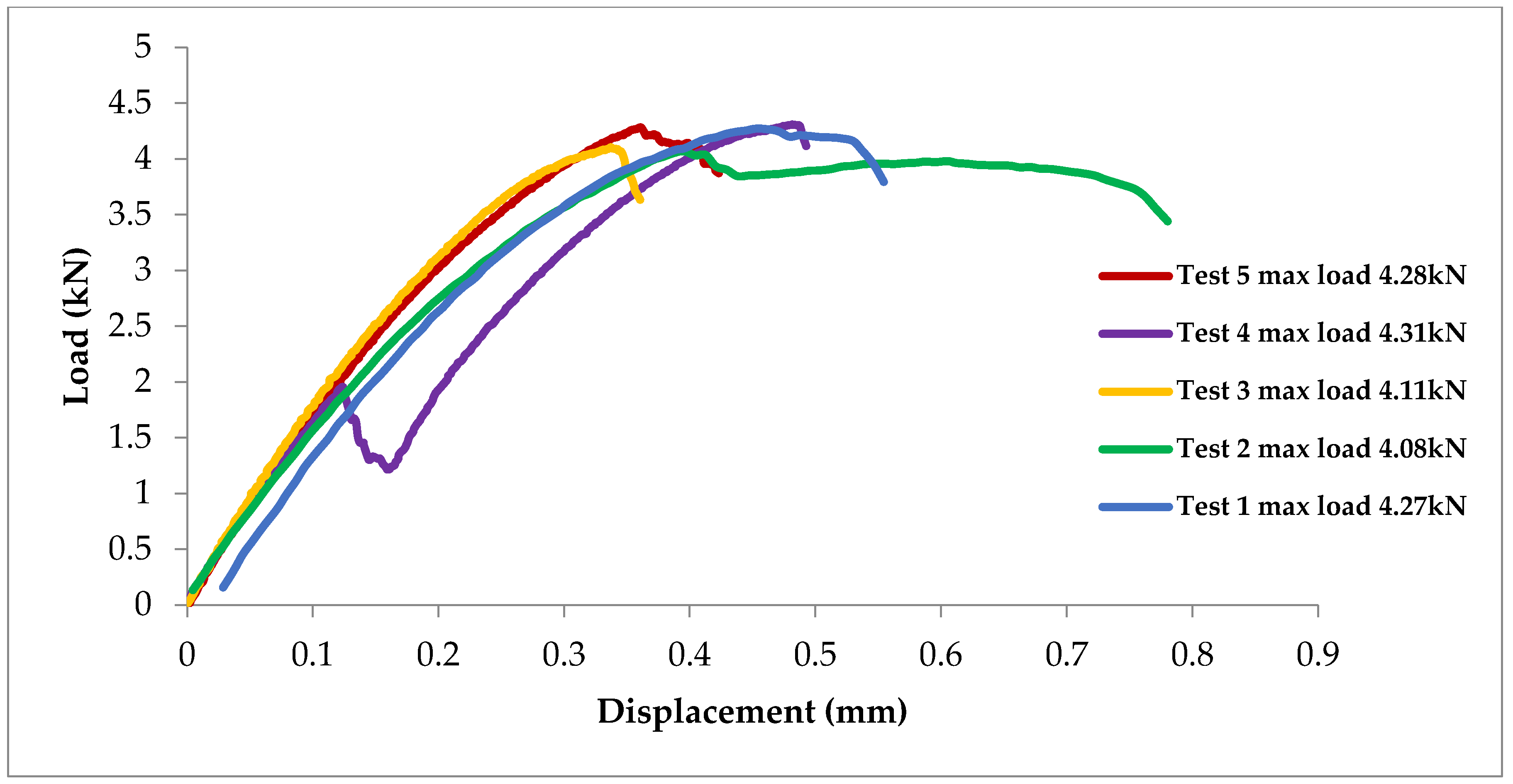
Quasi-static test samples were welded at 27 kA and 15 cycles, 2 pulses, with a 5-cycle delaying time. The average peak load was 4210 N, with a standard deviation of 112 N. All samples exhibited a similar behavior with a negligible amount of plasticity after the peak load; see Figure 8.
To assess the quality of the welds based on the tensile test results shown in Table 1, a comparison is made among the results with the strength of dissimilar joints using an interlayer in earlier studies available in the literature. According to Table 1, the average strength of 4.21 kN compares well with prior work, which ranged from 0.52 to 5.1 kN.

3.4. Microstructure Characterization

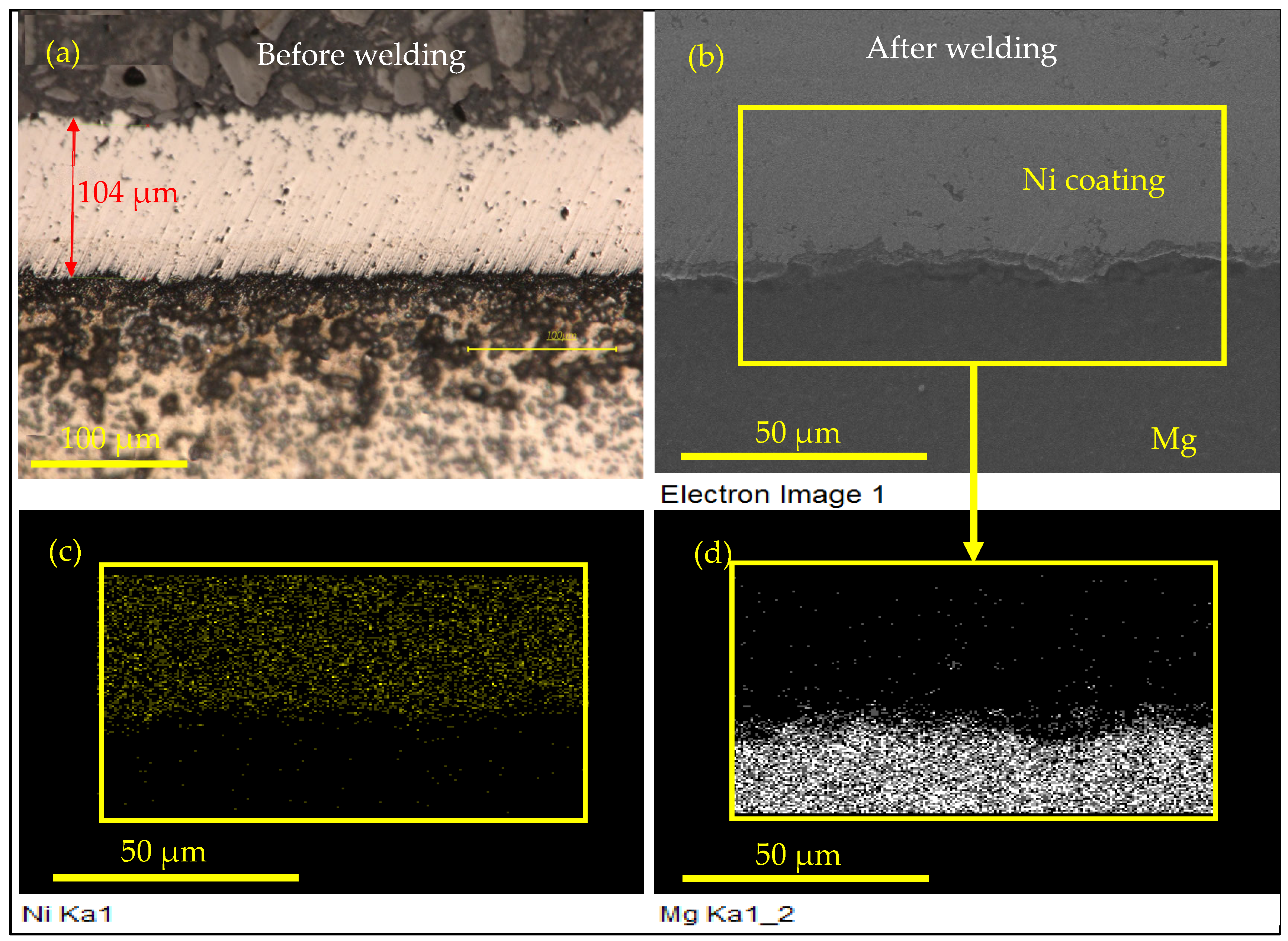
SEM images have been prepared to characterize the cold-spray-coated welded region between Ni-coated Al and Ni-coated Mg, and to evaluate the presence of intermetallics. Figure 9 shows the Ni-coated Al sheet before and after welding. The Ni coating layers contain micro-pores, as shown in Figure 9a. These micro-pores are reduced after welding due to the heat generated and the holding force of the electrodes, as shown in Figure 9b. Also, comparing the results before welding in Figure 9a with those after the weld in Figure 9b, there is clear evidence that Ni penetrated into the Al substrate side. The presence of Ni in the Al is confirmed by element analysis shown in Figure 9b–d. Figure 10 presents the Ni-coated Mg sheet before and after welding. As depicted in Figure 10b–d, a distinct interface is evident between Mg and Ni, in contrast to the Al/Ni mixture observed in Figure 9b–d, with no observable intermixing of the two elements. This indicates that the Ni–Al bond is stronger than the Ni–Mg bond, a conclusion further supported by the occurrence of interfacial fracture at the weld interface. The fracture initiates either from Mg entrapped within the Ni layer or from the Mg/Ni interface itself, as elaborated in Section 3.5 and Section 3.6.
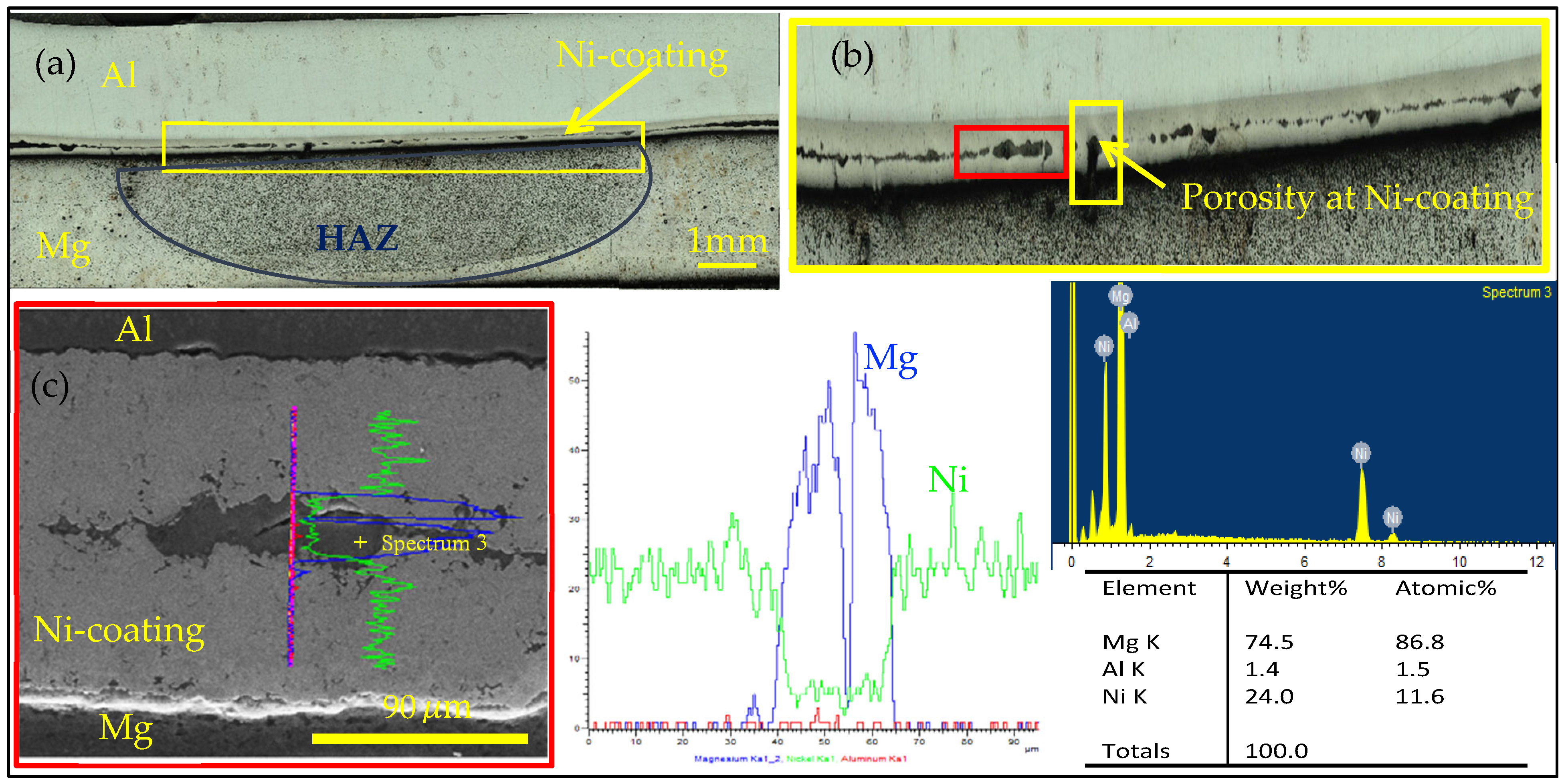
In general, these images show that the Ni coating successfully prevented the formation of IMCs between Al and Mg after the welding process, as shown in Figure 11c. However, a notable feature observed in the SEM results is the presence of voids that were created between the two welded Ni-coated layers after the weld, as depicted in Figure 11. Within these voids, traces of Mg were found, as shown in Figure 11c. The presence of Mg within the welded Ni coating shows that Mg penetrated through the porosities and into the thinner Ni coating layer, as shown in Figure 9a. These results are from samples that were not etched.
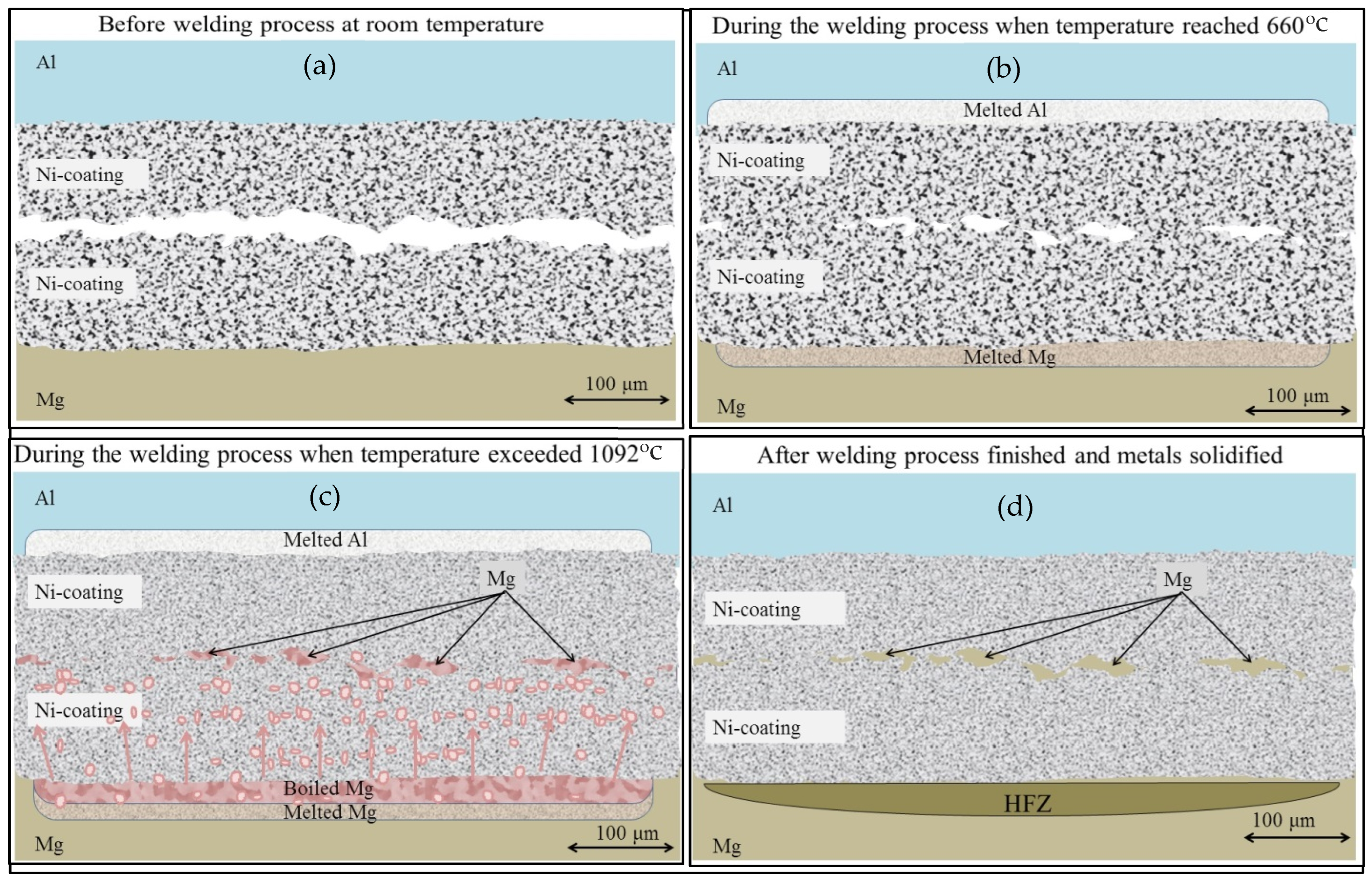
The joining of the Ni layers appears to be influenced by the presence of the Mg at the interface between welded Ni coating layers, as well as by the porosity of the coating. Considering the melting points of Ni (1455 °C), Mg (650 °C), and Al (660 °C), along with the forging temperature of Ni (approximately 1095–1455 °C) and the boiling point of Mg (1091 °C), the following mechanism is likely how Mg reached the Ni coating layers. During the RSW process, the successful bonding of the Ni coating layers suggests that the localized temperature reached at least the forging range of Ni. Given that the boiling temperature of Mg is below this range, it is possible that some Mg present at or near the interface evaporated during welding. This vaporized Mg then found its way into the interface region between the two Ni coating layers through existing porosity, or the thinner regions of the coating structure, as evidenced in Figure 9a. Additionally, the roughness of the Ni coating surface, shown in Figure 6, likely contributed to the formation of interfacial voids between the two coating layers, which could have acted as receptacles for the Mg vapor to condensate. Upon completion of the welding cycle and subsequent cooling, the Mg is trapped within these interfacial voids. This phenomenon is depicted in Figure 12, which shows the formation and entrapment of Mg within voids or cavities within the welded Ni coating layers.

3.5. Joining Mechanism

The joining mechanism can be delineated into two principal stages, as illustrated in Figure 1, at the conclusion of the Introduction. Initially, bonding between the cold-sprayed Ni coating and the underlying substrate is achieved through a combination of mechanical interlocking and metallurgical bonding inherent to the cold spray deposition process [33]. Subsequently, a secondary metallurgical bond is formed between the opposing Ni coating layers at their interface through resistance spot welding. The concurrent phenomena of mechanical interlocking and metallurgical bonding are widely recognized as the dominant adhesion mechanisms governing cold-sprayed coatings [1,34,35]. Post-welding, at the Al/Ni interfacial region, localized penetration of Ni into the Al substrate is observed. This embedded Ni is likely attributable to the initial layer of Ni particles that directly adhered to the Al substrate during the cold spray deposition. During the RSW process, localized melting of the Al at the Ni/Al interface (as depicted in Figure 12b,c) permits partial migration and entrapment of Ni particles within the molten Al matrix. Upon subsequent solidification of the Al, these Ni particles remain locked and metallurgically bonded within the solidified Al matrix, as evidenced in Figure 9b.
Following the cold spray deposition of Ni coatings on both substrates, the interfacial region between the coated Al and Mg substrates effectively transforms the dissimilar Al/Mg joint into a nominally similar Ni/Ni interface. The specimens coated on both sides were subsequently joined via the resistance spot welding process.
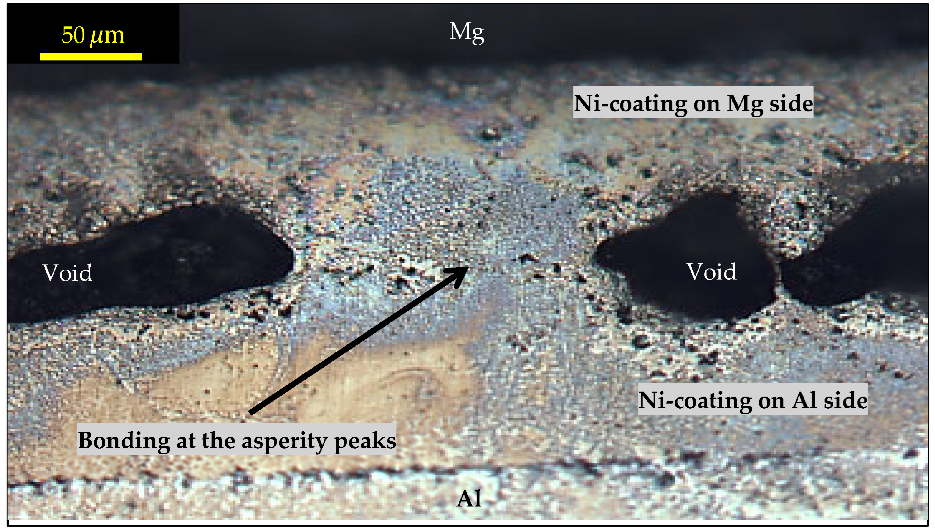
Due to the inherent surface topography of the cold-sprayed Ni coatings, characterized by asperities with peak-to-valley variations ranging from approximately 25 µm to 65 µm (Figure 6), contact at the faying interface primarily occurs at the crests of these surface asperities. This non-uniform contact leaves micro-gaps between the peaks, which act as sites for void formation during the welding process, as shown in Figure 11b,c and Figure 13. Consequently, these interfacial voids can be attributed directly to the surface roughness of the cold-sprayed coatings.
Additionally, the intrinsic porosity within the Ni coating, originating from the powder deposition process, in combination with the interfacial voids, contributes to localized increases in electrical resistance at the contact zones during RSW. These air gaps inherently exhibit high electrical resistivity, which promotes localized Joule heating, resulting in enhanced softening and partial melting at the asperity contact points on both the Al and Mg sides. This localized heating effect intensifies heat generation precisely at the welded faying surfaces, which is consistent with the bonding morphology observed in Figure 13, where the peaks of the Ni coating asperities are fused at the interface between the coated Al and coated Mg substrates.
Given that these asperity peaks are metallurgically bonded, it is inferred that the interfacial temperature locally reached the range bounded by the forging temperature of Ni (~1095 °C) and its melting point (~1455 °C). Achieving temperatures within this range is critical, as insufficient thermal input would preclude effective joining of the underlying Al and Mg sheets, thereby preventing the welded joint from sustaining significant loads under monotonic mechanical testing.

3.6. Fracture Mechanism

Examination of the fracture surface of the monotonic lap-shear test samples revealed no traces of Al/Mg IMCs, confirming that the cold-sprayed Ni interlayer effectively suppressed their formation. This absence of brittle IMCs contributed to the high ultimate load of 4.2 kN.
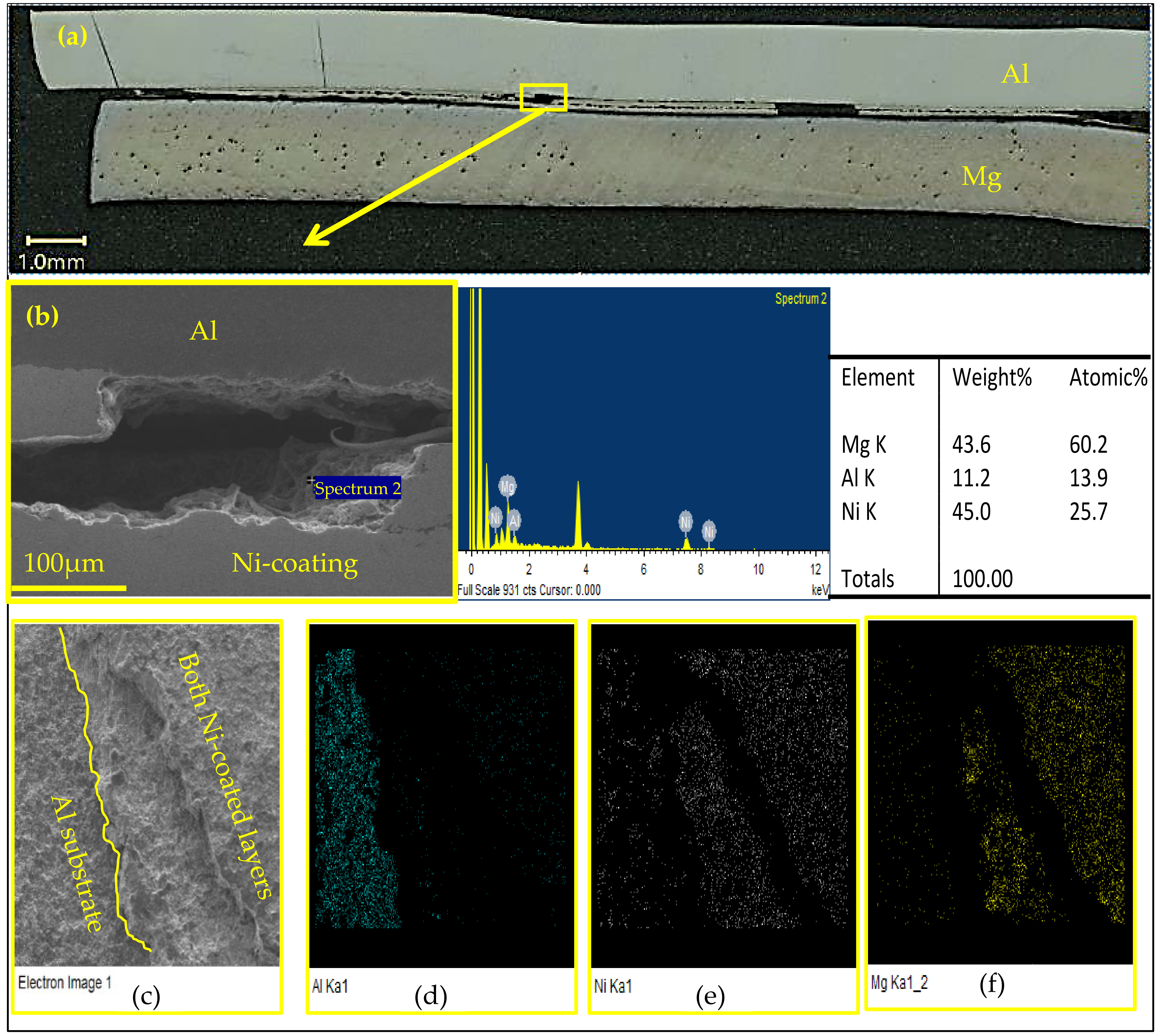
The cause of failure in all the quasi-static tests was either due to Mg penetration to the void at the Ni/Ni weld interface or at the Mg/Ni interface. The Mg infiltration was due to the inherent surface topography of the cold-sprayed Ni coatings. These porous regions (Figure 13), rich in Mg (Figure 14b), provided crack initiation points and subsequently propagated through the welded Ni-coated layer. This is depicted in Figure 14, which shows that the cracks propagate along the voids that contain traces of Mg on their walls. Figure 14a,b shows a cross-section at the welded area after failure in the monotonic test, and then the two halves of the sample were put together to study the fracture zone. Additionally, Figure 14 shows the fracture surface SEM evaluation in which spectrum 2 at (a) contains 43.6% weight percent Mg at the welded Ni-coated area (Figure 14b). The penetration of the Mg through the Ni-coat is attributed to the porosities that were created by the powder deposition and the asperities peak-to-valley of the Ni-coat surface and/or any thin-coated areas. Figure 14c–f shows the top view of the fracture surface on the Al side, (c) shows the Al substrate and two welded Ni-coating layers after failure in the monotonic test, (d) and (e) show the presence of the Al and the Ni, respectively. The Al side of the fracture surface examined by SEM, shown in Figure 14f, indicates there is Mg present on the fracture surface, with a negligible amount of Mg on the Al side (Al 6022 contains 0.45–0.7% Mg, Table 2), and certainly not enough to form IMCs. However, the small amount of Mg at the porosity shown in Figure 14b, at the interface of Ni and Al, contributed to cracking and failure along the Al/Ni interface.
Overall, the majority of the failures during the monotonic test occurred on the Mg side, specifically between the Mg substrate and the welded Ni coating. To mitigate Mg vapor through the Ni interlayer during RSW, optimizing cold spray parameters to increase the density and/or the thickness of the coat could be an effective strategy.

4. Conclusions

In this study, we have demonstrated that cold spray coating is an effective strategy for mitigating the formation of detrimental IMCs in Mg/Al dissimilar metal joints. The coating serves as a robust interlayer, enabling the joint to withstand tensile shear loads exceeding 4.2 kN. This mechanical performance can be further enhanced through optimization of the cold spray parameters, particularly those governing surface roughness, to minimize porosity and void formation at the Ni–Ni weld region. It was observed that residual porosity facilitated the migration of magnesium into interfacial voids, leading to the formation of Mg-rich regions that ultimately acted as initiation sites for failure. From the results shown, the following conclusions can be drawn:
  • Ni-coated layer successfully prevented the direct interaction between the Al and Mg after the welding process, and the formation of undesirable Al/Mg IMCs.
  • The peak load of 4.2 kN was achieved in the tensile lap-shear test of Al/Mg RSW samples with cold-sprayed Ni-coating interlayer, which meets the required load capacity based on AWS standards for similar sheet joints.
  • The mechanism of Mg penetrating into the Ni/Ni weld region was established. It was shown that, due to excessive local heat, vaporized Mg found its way through the coating porosity.
  • The fracture mechanism of joints during mechanical testing was attributed to the roughness of the coated Ni layer, which caused voids/porosity at the weld surface, acting as the stress concentration area, in addition to the presence of porosity within the interlayer, which contained Mg that migrated from the sheet during welding.

Author Contributions

Conceptualization, H.J. and A.G.; methodology, M.O. and D.S.; validation, M.O., D.S., A.G. and H.J.; formal analysis, M.O.; investigation, M.O. and D.S.; resources, A.G. and H.J.; data curation, M.O. and D.S.; writing—original draft preparation, M.O., D.S. and H.J.; writing—review and editing, A.G. and H.J.; visualization, M.O. and D.S.; supervision, A.G. and H.J.; funding acquisition, A.G. and H.J. All authors have read and agreed to the published version of the manuscript.

Funding

This research was financially supported by the Natural Sciences and Engineering Council of Canada through Grants RGPIN-2019-05636 and RGPIN-2020-05135.

Data Availability Statement

The raw data supporting the conclusions of this article will be made available by the authors on request.

Conflicts of Interest

The authors declare no conflicts of interest.

References

  1. Alkhimov, A.P.; Kosarev, V.F.; Papyrin, A.N. A method of “cold” gas-dynamic spraying. Dokl. Akad. Nauk. SSSR 1990, 315, 1062–1065. [Google Scholar]
  2. Alkimov, A.N.P.A.P.; Kosarev, V.F.; Nesterovich, N.I. Method of Applying Coatings. Russian Patent No. 1,618,778; SU 1618778, 7 January 1991. [Google Scholar]
  3. Hassani-Gangaraj, M.; Veysset, D.; Nelson, K.A.; Schuh, C.A. In-situ observations of single micro-particle impact bonding. Scr. Mater. 2018, 145, 9–13. [Google Scholar] [CrossRef]
  4. Meng, F.; Yue, S.; Song, J. Quantitative prediction of critical velocity and deposition efficiency in cold-spray: A finite-element study. Scr. Mater. 2015, 107, 83–87. [Google Scholar] [CrossRef]
  5. Hassani-Gangaraj, M.; Veysset, D.; Nelson, K.A.; Schuh, C.A. Melting Can Hinder Impact-Induced Adhesion. Phys. Rev. Lett. 2017, 119, 175701. [Google Scholar] [CrossRef] [PubMed]
  6. Grujicic, M.; Zhao, C.L.; DeRosset, W.S.; Helfritch, D. Adiabatic shear instability based mechanism for particles/substrate bonding in the cold-gas dynamic-spray process. Mater. Des. 2004, 25, 681–688. [Google Scholar] [CrossRef]
  7. Assadi, H.; Schmidt, T.; Richter, H.; Kliemann, J.-O.; Binder, K.; Gärtner, F.; Klassen, T.; Kreye, H. On parameter selection in cold spraying. J. Therm. Spray Technol. 2011, 20, 1161–1176. [Google Scholar] [CrossRef]
  8. Yin, S.; Wang, X.; Suo, X.; Liao, H.; Guo, Z.; Li, W.; Coddet, C. Deposition behavior of thermally softened copper particles in cold spraying. Acta Mater. 2013, 61, 5105–5118. [Google Scholar] [CrossRef]
  9. Yin, S.; Meyer, M.; Li, W.; Liao, H.; Lupoi, R. Gas Flow, Particle Acceleration, and Heat Transfer in Cold Spray: A review. J. Therm. Spray Technol. 2016, 25, 874–896. [Google Scholar] [CrossRef]
  10. Moridi, A.; Hassani-Gangaraj, S.M.; Guagliano, M.; Dao, M. Cold spray coating: Review of material systems and future perspectives. Surf. Eng. 2014, 30, 369–395. [Google Scholar] [CrossRef]
  11. Villafuerte, J. Modern Cold Spray: Materials, Process, and Applications, 1st ed.; Springer International Publishing: Windsor, ON, Canada, 2015. [Google Scholar] [CrossRef]
  12. Lara, B.; Giorjao, R.; Ramirez, A. Resistance spot welding of printed interlayers to join Al–Fe sheets. Sci. Technol. Weld. Join. 2023, 28, 18–26. [Google Scholar] [CrossRef]
  13. Szwajka, K.; Zielińska-Szwajka, J.; Szewczyk, M.; Mezher, M.T.; Trzepieciński, T. Analysis of the Microstructure and Mechanical Performance of Resistance Spot-Welding of Ti6Al4V to DP600 Steel Using Copper/Gold Cold-Sprayed Interlayers. Materials 2024, 17, 3251. [Google Scholar] [CrossRef]
  14. Hagen, C.; Klinkenberg, F.-J.; Ossenbrink, R.; Michailov, V. Resistance spot welding of dissimilar material joints with a cold-gas-sprayed inlayer. Int. J. Adv. Manuf. Technol. 2023, 127, 5679–5690. [Google Scholar] [CrossRef]
  15. Liu, L.; Ren, D.; Liu, F. A review of dissimilar welding techniques for magnesium alloys to aluminum alloys. Materials 2014, 7, 3735–3757. [Google Scholar] [CrossRef]
  16. Zhang, Y.; Luo, Z.; Li, Y.; Liu, Z.M.; Huang, Z.Y. Microstructure characterization and tensile properties of Mg/Al dissimilar joints manufactured by thermo-compensated resistance spot welding with Zn interlayer. Mater. Des. 2015, 75, 166–173. [Google Scholar] [CrossRef]
  17. Penner, P.; Liu, L.; Gerlich, A.; Zhou, Y. Feasibility study of resistance spot welding of dissimilar Al/Mg combinations with Ni based interlayers. Sci. Technol. Weld. Join. 2013, 18, 541–550. [Google Scholar] [CrossRef]
  18. Penner, P.; Liu, L.; Gerlich, A.; Zhou, Y. Dissimilar resistance spot welding of aluminum to magnesium with Zn-coated steel interlayers. Weld. J. 2014, 93, 225–231. [Google Scholar]
  19. Sun, M.; Niknejad, S.T.; Zhang, G.; Lee, M.K.; Wu, L.; Zhou, Y. Microstructure and mechanical properties of resistance spot welded AZ31/AA5754 using a nickel interlayer. Mater. Des. 2015, 87, 905–913. [Google Scholar] [CrossRef]
  20. Sun, M.; Niknejad, S.T.; Gao, H.; Wu, L.; Zhou, Y. Mechanical properties of dissimilar resistance spot welds of aluminum to magnesium with Sn-coated steel interlayer. Mater. Des. 2016, 91, 331–339. [Google Scholar] [CrossRef]
  21. Sun, M.; Behravesh, S.B.; Wu, L.; Zhou, Y.; Jahed, H. Fatigue behaviour of dissimilar Al 5052 and Mg AZ31 resistance spot welds with Sn-coated steel interlayer. Fatigue Fract. Eng. Mater. Struct. 2017, 40, 1048–1058. [Google Scholar] [CrossRef]
  22. Manladan, S.M.; Yusof, F.; Ramesh, S.; Fadzil, M. A review on resistance spot welding of magnesium alloys. Int. J. Adv. Manuf. Technol. 2016, 86, 1805–1825. [Google Scholar] [CrossRef]
  23. Cooke, K.O.; Khan, T.I. Resistance spot welding aluminium to magnesium using nanoparticle reinforced eutectic forming interlayers. Sci. Technol. Weld. Join. 2018, 23, 271–278. [Google Scholar] [CrossRef]
  24. Panteli, A.; Chen, Y.-C.; Strong, D.; Zhang, X.; Prangnell, P.B. Optimization of aluminium-to-magnesium ultrasonic spot welding. JOM 2012, 64, 414–420. [Google Scholar] [CrossRef]
  25. Panteli, A.; Robson, J.D.; Chen, Y.C.; Prangnell, P.B. The effectiveness of surface coatings on preventing interfacial reaction during ultrasonic welding of aluminum to magnesium. Metall. Mater. Trans. A 2013, 44, 5773–5781. [Google Scholar] [CrossRef]
  26. Hou, W.; Oheil, M.; Shen, Z.; Shen, Y.; Jahed, H.; Gerlich, A. Enhanced strength and ductility in dissimilar friction stir butt welded Al/Cu joints by addition of a cold-spray Ni interlayer. J. Manuf. Process. 2020, 60, 573–577. [Google Scholar] [CrossRef]
  27. Hou, W.; Shen, Z.; Huda, N.; Oheil, M.; Shen, Y.; Jahed, H.; Gerlich, A.P. Enhancing metallurgical and mechanical properties of friction stir butt welded joints of Al–Cu via cold sprayed Ni interlayer. Mater. Sci. Eng. A 2021, 809, 140992. [Google Scholar] [CrossRef]
  28. Dong, S.-K.; Lin, S.; Zhu, H.; Wang, C.-J.; Cao, Z.-L. Effect of Ni interlayer on microstructure and mechanical properties of Al/Mg dissimilar friction stir welding joints. Sci. Technol. Weld. Join. 2022, 27, 103–113. [Google Scholar] [CrossRef]
  29. CenterLine (Windsor) Limited, Supersonic Spray Technologies Div. SST-TDS-N5001-PR-2.0-0120, Technical Data Sheet: SST-N5001 Powder, Release Date: January 2020. Available online: https://www.supersonicspray.com/uploads/documents/SST-TDS-N5001-PR-2_0-0120.pdf (accessed on 15 August 2025).
  30. Özbilen, S.; Vasquez, J.F.B.; Abbott, W.M.; Yin, S.; Morris, M.; Lupoi, R. Mechanical milling/alloying, characterization and phase formation prediction of Al0.1–0.5(Mn)CoCrCuFeNi-HEA powder feedstocks for cold spray deposition processing. J. Alloys Compd. 2023, 961, 170854. [Google Scholar] [CrossRef]
  31. Kang, J.; McDermid, J.R.; Bruhis, M. Determination of the constitutive behaviour of AA6022-T4 aluminium alloy spot welds at large strains. Mater. Sci. Eng. A 2013, 567, 95–100. [Google Scholar] [CrossRef]
  32. Giraud, E.; Rossi, F.; Germain, G.; Outeiro, J.C. Constitutive modelling of AZ31B-O magnesium alloy for cryogenic machining. Procedia CIRP 2013, 8, 522–527. [Google Scholar] [CrossRef]
  33. Tang, Q.; Veysset, D.; Assadi, H.; Ichikawa, Y.; Hassani, M. Strength gradient in impact-induced metallic bonding. Nat. Commun. 2024, 15, 9630. [Google Scholar] [CrossRef]
  34. Assadi, H.; Gärtner, F.; Stoltenhoff, T.; Kreye, H. Bonding mechanism in cold gas spraying. Acta Mater. 2003, 51, 4379–4394. [Google Scholar] [CrossRef]
  35. Ito, K. Mechanistic Analysis of Cold Sprayed Particle Deposition Behavior by Single Particle Impact Testing System and Improvement of Coating Properties. Ph.D. Thesis, Tohoku University, Sendai, Japan, 12 January 2016. [Google Scholar]
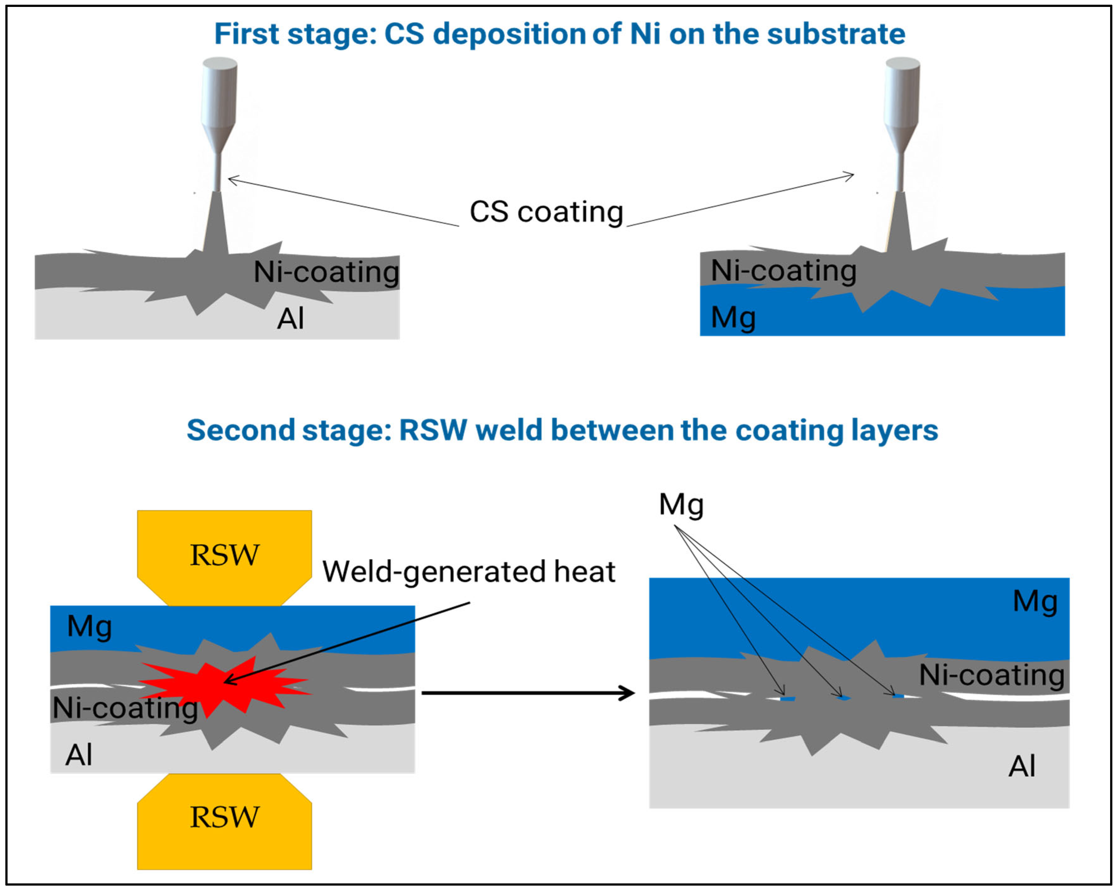
Figure 1. A graphical visualization of the processes that lead to final adhesion joint of the coating Al/Mg. First stage, illustrated in the top two images, is bonding between coating layer and substrate during CS process by interlock phenomena. The second stage, illustrated in the bottom images, involves joining the Ni coating layers on the Al side to those on the Mg side during the RSW process by welding them together. Further details are provided in the following sections. The joining mechanism, in which Mg ends up embedded between the Ni–Ni weld, is explained in Section 3.5.
Metals 15 00940 g001
Figure 2. (a) SEM image shows the particle shape and size of Ni powder, and; (b) size distribution [30].
Metals 15 00940 g002
Figure 3. The cold spray gun and nozzle during Ni-coating process using nitrogen as process gas.
Metals 15 00940 g003
Figure 4. Schematic of lap-shear configuration with associated dimensions.
Metals 15 00940 g004
Figure 5. (a) Coatings on Al and Mg coupons before the welding process and (b) weld interface region following welding and subsequent lap-shear testing, with a magnified view of the area highlighted in the red box, accompanied by elemental point analysis of the Ni coating on the Al (spectrum 1) and Mg (spectrum 2) sides.
Metals 15 00940 g005
Figure 6. Three-dimensional scan of 1 × 1 mm of Ni coating on Al substrate that shows the roughness of 1 mm2 of the coating surface. (a) Ni coating on Al sample and the test position before the weld; (b) Top view of the 3D scan; (c) Side view of the 3D scan.
Metals 15 00940 g006
Figure 7. Metallography of cross-sectioned welds between Ni-coated Al to Ni-coated Mg produced with varying currents. (a) Welded at 26 kA and 15 cycles 2 pulses with delaying time 5 cycles; (b) Welded at 27 kA and 15 cycles 2 pulses with delaying time 5 cycles that show the larges bonding area and; (c) Welded at 28 kA and 15 cycles 2 pulses with delaying time 5 cycles off.
Metals 15 00940 g007
Figure 8. Load displacement curves obtained from lap-shear specimens produced using welded parameters: −27 kA and 15 cycles, 2 pulses, with 5-cycle delaying time that was applied for all samples.
Metals 15 00940 g008
Figure 9. SEM images of the Al-coated sheet before (a) and after (bd) welding. (a) shows a clear interface between coating and the substrate, porosity in coating, and uneven thickness of coating. (b) Show a mixed Al-Ni region between coating and substrate, confirmed by line element analysis (red: Al and green: Ni), lower porosity in the coating, and even thickness of Ni layer. (c,d) Show the presence of both Ni and Al in around 30 μm thick region at the interface between Ni coating and Al substrate, shown by the white box in (b).
Metals 15 00940 g009
Figure 10. SEM images of the Mg-coated sheet before (a) and after (bd) welding. (a) shows the interface between coating and the substrate, and uniform thickness of coating; (b) interface between Ni and Mg after welding, showing a distinct Mg-Ni region between coating and substrate, confirmed by element analysis shown in (c,d), (white: Mg and yellow: Ni).
Metals 15 00940 g010
Figure 11. Sample after welding showing (a) Details of the weld area and; (b) Higher magnification image of porosity at welded Ni-coated layer in the yellow box; (c) Details of one of the areas (red rectangle in (b)), in the middle of Ni showing presence of Mg with further line element analysis inside this area showing heavy to moderate presence of Mg. The middle figure in (c) shows the element distribution that includes Mg and Ni, with element peaks shown in the far-right figure in (c) along with the weight%.
Metals 15 00940 g011
Figure 12. Schematic representation of the joining mechanisms occurring at critical temperatures during the resistance spot welding process, highlighting the interaction behavior of Ni, Al, and Mg. (a) Initial positioning of the specimen for welding; (b) Progression as the interfacial temperature reaches the melting points of Al and Mg; (c) At the boiling point of Mg (~1092 °C) and the forging temperature of Ni (~1095 °C), vaporized Mg migrates through the inherent porosity of the Ni coating, accumulating within interfacial voids between the opposing Ni layers; (d) Final stage illustrating the completion of the welding process and formation of the bonded joint.
Metals 15 00940 g012
Figure 13. Microstructural evidence of bonding at the asperity peaks of the cold-sprayed Ni coatings at the faying interface formed during the resistance spot welding process. The image also illustrates the presence of voids generated in the regions where the rough Ni-coated surfaces were in partial contact.
Metals 15 00940 g013
Figure 14. Fracture surfaces and failure characteristics influenced by coating voids, indicating a relatively high concentration of Mg at the fracture path. (a) Cross-section of sample after quasi-static failure with the two sides reassembled; (b) magnified SEM image of the cross-section after quasi-static failure; (cf) SEM top-view images of the fracture surface within the coating layers; (f) highlights significant Mg content along the fracture path.
Metals 15 00940 g014
Table 1. Summary of dissimilar Mg/Al RSW joining studies [22].
Weld ProcessSheet MaterialsInterlayer MaterialInterlayer TypeStrength (kN)Ref.
Conventional RSWAZ31B Mg/Al 5754Pure nickelInsert foilno bonding[17]
Conventional RSWAZ31B Mg/Al 5754Pure nickelInsert foil5.1[19]
Conventional RSWAZ31B Mg/Al 5754Gold-coated nickel foilInsert foil4.69[17]
Conventional RSWAZ31B Mg/Al 5754Zinc-coated HSLA steelInsert foil3.86[18]
Conventional RSWAZ31B Mg/Al 5754(1) Ni
(2) Ni-TiO3
(3) Ni-Al2O3
Electrodeposit(1) 0.45
(2) 0.48
(3) 0.52
[23]
Conventional RSWAZ31B Mg/Al 5052-H12Zinc interlayerInsert foil0.727[16]
Thermo-compensated RSWAZ31B Mg/Al 5052-H12Zinc interlayerInsert foil2.199[16]
Conventional RSWAZ31B Mg/Al 5052-H12No interlayerNo interlayer0.833[16]
Table 2. Chemical composition of the Al AA6022-T4 [31] and Mg AZ31B-O (wt. %) sheet base metals [32].
Al 6022-T4 (wt. %)
SiFeCuMnMgCrZnTiAl
0.8–1.50.05–0.20.01–0.110.02–0.10.45–0.7≤0.1≤0.25≤0.15Balance
Mg AZ31B-O (wt. %)
AlZnMnSiCuCaNiFeMg
2.5–3.50.6–1.4≥0.2≤0.1≤0.005≤0.004≤0.005≤0.005balance
Table 3. Cold spray coating parameters used for deposition of nickel on both substrates.
Coating MaterialsNi on MgNi on Al
Flow GasN2N2
Gas Temperature (°C)500500
Gas Pressure (MPa)1.51.5
Powder Feed Rate (gr/min)88
Nozzle Speed (mm/s)2525
Step Over (mm)2.73
Stand-off Distance (mm)1212
Nozzle Length (mm)120120
Nozzle Orifice Diameter (mm)22
Nozzle Exit Diameter (mm)6.36.3
Type of Nozzlede Laval UltiLifeTM
Table 4. Summary of welding parameters examined.
Welding Current (kA)Two Pulse Welding Time (Cycles)Delay Time
151820(Cycles)
26Test 1Test 7Test 135
27Test 2Test 8Test 145
28Test 3Test 9Test 155
26Test 4Test 10Test 1610
27Test 5Test 11Test 1710
28Test 6Test 12Test 1810
Disclaimer/Publisher’s Note: The statements, opinions and data contained in all publications are solely those of the individual author(s) and contributor(s) and not of MDPI and/or the editor(s). MDPI and/or the editor(s) disclaim responsibility for any injury to people or property resulting from any ideas, methods, instructions or products referred to in the content.