Article

Research on Hybrid Blue Diode-Fiber Laser Welding Process of T2 Copper

1
School of Materials, Shanghai Dianji University, No. 300, Shuihua Road, Pudong New Area, Shanghai 200245, China
2
Shanghai Aerospace Equipments Manufacturer Co., Ltd., Shanghai 200245, China
3
Heilongjiang Construction & Installation Group Co., Ltd., Harbin 150036, China
*
Authors to whom correspondence should be addressed.
Metals 2025, 15(9), 1058; https://doi.org/10.3390/met15091058
Submission received: 8 August 2025 / Revised: 2 September 2025 / Accepted: 16 September 2025 / Published: 22 September 2025
(This article belongs to the Special Issue Advanced Laser Welding and Joining of Metallic Materials)

Abstract

This research proposes a non-penetration lap welding process for joining T2 copper power module terminals in high-frequency and high-power electronic applications, using a hybrid laser system combining a 445 nm blue diode laser and a 1080 nm fiber laser. The composite laser beam, formed by coupling a circular blue laser beam with a spot-shaped fiber laser beam, was oscillated along circular, sinusoidal, and 8-shaped trajectories to control weld geometry and joint quality. Results indicate that all trajectories produced U-shaped weld cross-sections with smooth toe transitions and good surface quality. Specifically, the circular trajectory provided uniform energy distribution and stable weld formation; the 8-shaped trajectory achieved a balanced width-to-depth ratio; and the sinusoidal trajectory exhibited sensitivity to welding speed, often resulting in uneven fusion width. Increased welding speed promoted grain refinement, but excessive speed led to porosity and poor surface quality in both 8-shaped and sinusoidal trajectories. Oscillating laser welding facilitated equiaxed grain formation, with the circular and 8-shaped trajectories yielding more uniform microstructures. The circular trajectory maintained consistent weld dimensions and hardness distribution, while the 8-shaped trajectory exhibited superior tensile strength. This work highlights the potential of circular and 8-shaped trajectories in hybrid laser welding for regulating weld microstructure, enhancing mechanical performance and ensuring weld stability.

1. Introduction

With the ongoing trend of miniaturization, high performance, and low power consumption in electronic products, the demands for the connection quality and efficiency of copper power terminals in power electronic devices, such as IGBTs, have become increasingly stringent. Copper and its intrinsic joining methods, enabled by its excellent electrical and thermal conductivities, are gaining increasing importance [1,2]. The applications span a wide range of scales—from the microscale to the millimeter scale—covering diverse joint geometries, such as interconnections in power semiconductor modules [3] and high-current conductors, commonly referred to as busbars. However, its high reflectivity and superior thermal conductivity pose significant challenges for conventional welding methods when processing copper. Traditional manual arc welding and manual TIG welding techniques often suffer from insufficient power density, making it difficult to achieve ideal welding results [4,5]. Kim HT et al. found that with increasing energy input during ultrasonic welding of copper terminals, deformation intensified, and cracks appeared along the edges. In contrast, low energy levels resulted in unbonded regions, adversely affecting the performance of power modules [6]. Therefore, there is an urgent need for a novel welding technology to overcome these challenges and improve both the quality and efficiency of copper welding.
Laser welding emerges as a promising technique to achieve this objective due to its inherent advantages, including high power density, low heat input, large aspect ratio, and a narrow heat-affected zone (HAZ) [7,8]. Vincenzo Dimatteo et al. investigated the influence of process parameters on laser welding of pure copper. Their results demonstrated that optimized parameters significantly reduced porosity to below 1%, while achieving a tensile load capacity of up to 490 N. This indicates a substantial improvement in weld integrity and mechanical performance, confirming the potential of laser welding for high-quality copper joints [9]. Arjmand E et al. investigated the laser welding process of copper terminals to DCB substrates in discrete power semiconductor packages. They found that, compared with conventional techniques, laser welding improved the shear strength by 50% [10]. Alter L et al. employed a 515 nm wavelength laser to weld pure copper, achieving a stable and reliable conduction-mode welding process at high welding speeds, with no spatter generation [11]. Haubold M et al. pointed out that, compared with conventional infrared lasers, green lasers exhibit a significantly higher absorption coefficient for copper materials, thereby enhancing energy utilization efficiency [1]. Chung W.S. et al. further demonstrated, by comparing the metal bonding process using laser pulses with wavelengths of 515 nm and 1064 nm, that copper exhibits a significantly higher absorption rate for the 515 nm wavelength [12]. These studies indicate that short-wavelength lasers offer distinct advantages in welding copper and its alloys. In contrast traditional long-wavelength lasers suffer from limited absorption, thus constraining welding efficiency and quality. Based on these findings, the blue–fiber hybrid laser technology—combining a 445 nm blue laser for preheating and a 1070 nm fiber laser for deep penetration—synergistically improves weld quality and process efficiency by leveraging the high absorptivity of blue light and the deep penetration capability of the fiber laser.
In recent years, numerous studies have confirmed the advantages and application potential of blue–fiber hybrid laser welding technology. Hai Cai et al. demonstrated that, in lap welding of 3 mm thick copper, the addition of blue laser significantly increased near-infrared absorption, resulting in improved weld density and stability [13]. Hang Yang et al. reported that dual-beam hybrid welding using 450 nm and 1060 nm lasers enhanced fiber laser absorption by approximately 20%, effectively optimizing weld formation [14]. Fujio S et al. conducted welding experiments on pure copper using a red–blue hybrid laser source. The results showed that, compared with single-fiber laser welding, the hybrid system improved welding efficiency by approximately 1.45 times and increased the melt pool volume by around 1.8 times, thereby significantly enhancing weld compactness and stability [15]. Dongsheng Wu et al. investigated the molten pool dynamics and laser energy absorption characteristics during coaxial blue–infrared hybrid laser welding of copper. Their findings revealed that the preheating effect of the blue laser significantly increased and stabilized the infrared laser absorption, optimizing energy distribution and molten pool morphology during welding [16]. Shumpei Fujio et al. further reported that blue laser preheating enlarged the molten pool volume by 1.8 times, increased welding efficiency by 1.45 times, and simultaneously suppressed spatter and porosity formation [17].
In summary, the blue–fiber hybrid laser welding technology, leveraging the high absorption of blue light and the deep penetration capability of fiber laser, has significantly enhanced the welding stability, weld quality, and efficiency of copper materials, providing an innovative approach for high-performance copper joining. Current research mainly focuses on thick plates or wire welding. At the same time, systematic parameter optimization and performance evaluation for non-penetration lap joints of 0.5 mm thick T2 copper power terminals remain insufficiently explored. Therefore, this study simplifies the IGBT power terminal structure to 0.5 mm thick T2 copper lap specimens and conducts blue–fiber hybrid laser non-penetration welding experiments. The objective is to clarify the influence of key process parameters on weld formation and mechanical properties, thereby providing theoretical and practical guidance for efficient and reliable joining of ultra-thin copper terminals.

2. Materials and Methods

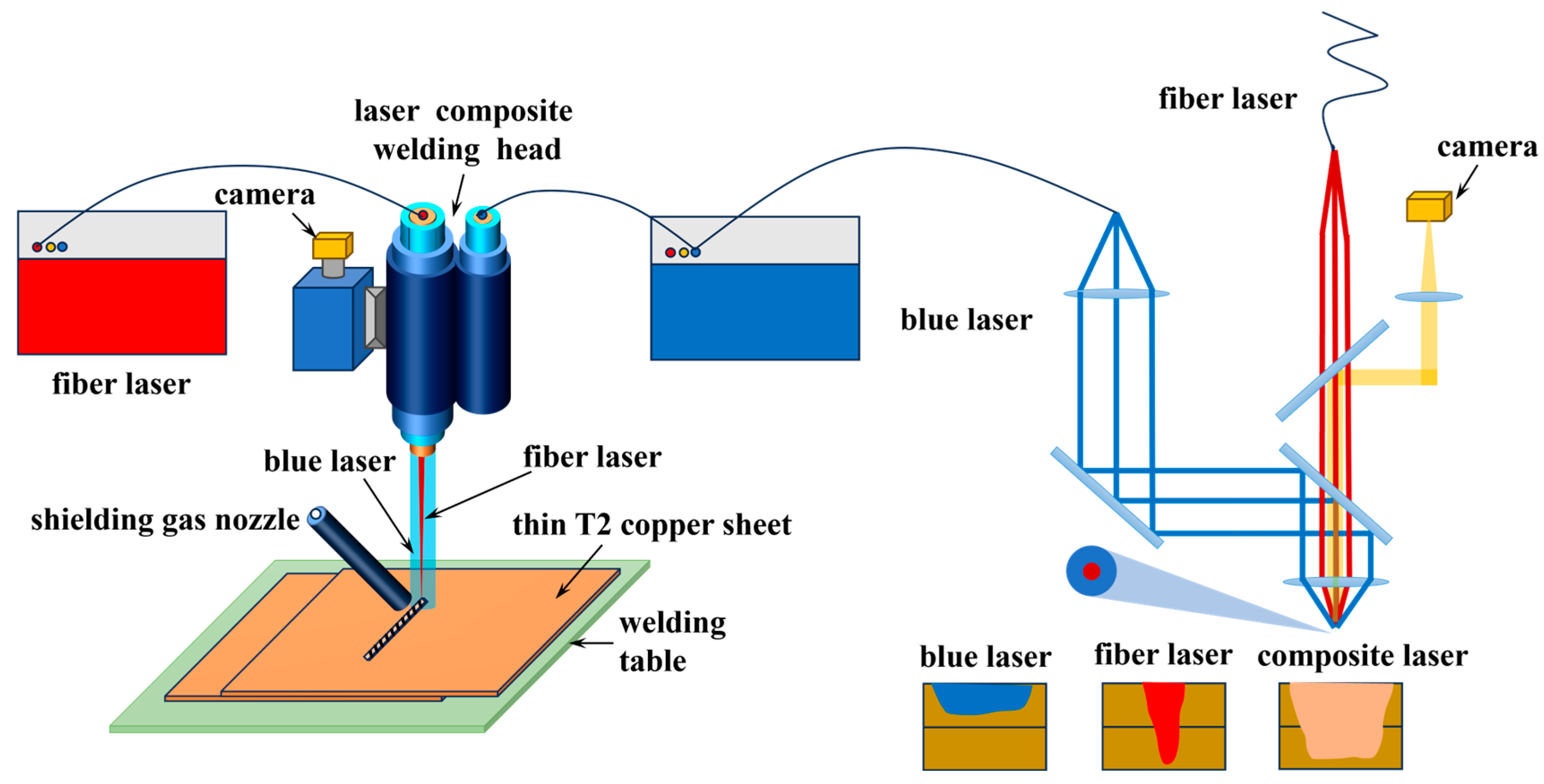
The experimental material was T2 copper with a sheet thickness of 0.5 mm and dimensions of 100 mm × 100 mm × 0.5 mm. Its chemical composition is listed in Table 1.The key parameters of the blue laser and fiber laser used in the experiments are shown in Table 2. The blue–fiber composite laser welding system comprised an RFL-B500D blue laser, an RFL-1500/1500 fiber laser with adjustable beam mode, and an ND36 laser composite welding head, as illustrated in Figure 1. The welding parameters and trajectory settings were controlled using the C6L fiber welding control system. The laser welding system and the C6L fiber welding control system were provided by Wuhan Raycus Fiber Laser Technologies Co., Ltd, Wuhan, China.
The welding method employed a blue–fiber composite laser welding technique, where the blue laser formed a ring-shaped spot with a diameter of 1000 μm, and the fiber laser was positioned at the center of the blue laser ring, creating a circular spot with a diameter of 50 μm. The schematic diagram of the blue–fiber composite laser welding process is shown in Figure 2. The blue laser power was set to 300 W, and the fiber laser power to 600 W. Argon was used as the shielding gas at a flow rate of 15 L/min. In the present study the shielding gas flow rate was fixed at 15 L/min to isolate the effects of welding speed and oscillation trajectory. The T2 copper sheets were mechanically polished and ultrasonically cleaned in ethanol before welding. The chosen power (blue laser 300 W, fiber laser 600 W) and speeds (15–25 mm/s) were based on pretests ensuring stable keyhole formation and reference studies [9,13], which confirmed their effectiveness in copper welding. The welding parameters were chosen based on both literature reports and preliminary trials. Speeds of 15–25 mm/s represent typical low-to-high regimes in copper welding, while the constant shielding gas flow and laser power ensured stable keyhole behavior. These conditions enabled a systematic evaluation of oscillation trajectory effects on weld formation and properties. During welding, two copper plates were lap-jointed and fixed using a fixture. Welding was conducted under three trajectory conditions: circular, 8-shaped, and sinusoidal, as illustrated in Figure 3. The weld seam width was set to 2 mm. Relevant process parameters are listed in Table 3. All experiments were performed on a calibrated [Blue laser–fiber laser hybrid welding system, positioning accuracy ±0.01 mm, power fluctuation within ±1.5%]. The reproducibility of the results was confirmed by three independent trials, and the observed differences were within the experimental error, indicating negligible influence of equipment inaccuracy.
The weld surface and the macroscopic morphology of the welded joints were observed using a stereomicroscope, and parameters such as welding trajectory spacing, weld width, and weld penetration depth were measured. The welded joints were sectioned transversely by laser cutting to prepare metallographic specimens. After grinding and polishing, the specimens were etched with a ferric chloride–hydrochloric acid solution and examined under an optical microscope to observe the microstructure. Micro-Vickers hardness testing was performed on the transverse cross-section of the welded joints. Measurements were taken every 0.2 mm from the weld centerline toward the base metal at a position one-third from the top of the weld seam. The applied load was 1 N with a dwell time of 10 s. The indent diagonal lengths during Vickers microhardness testing ranged from ~42 μm (at maximum hardness of 102.8 HV) to ~50 μm (at minimum hardness of 72.5 HV), which ensured accurate measurement without interference from adjacent features. Tensile tests were conducted using a universal testing machine at a tensile rate of 1 mm/min.

3. Results and Discussion

3.1. Effect of Welding Trajectory and Speed on Weld Formation

3.1.1. Weld Appearance Analysis

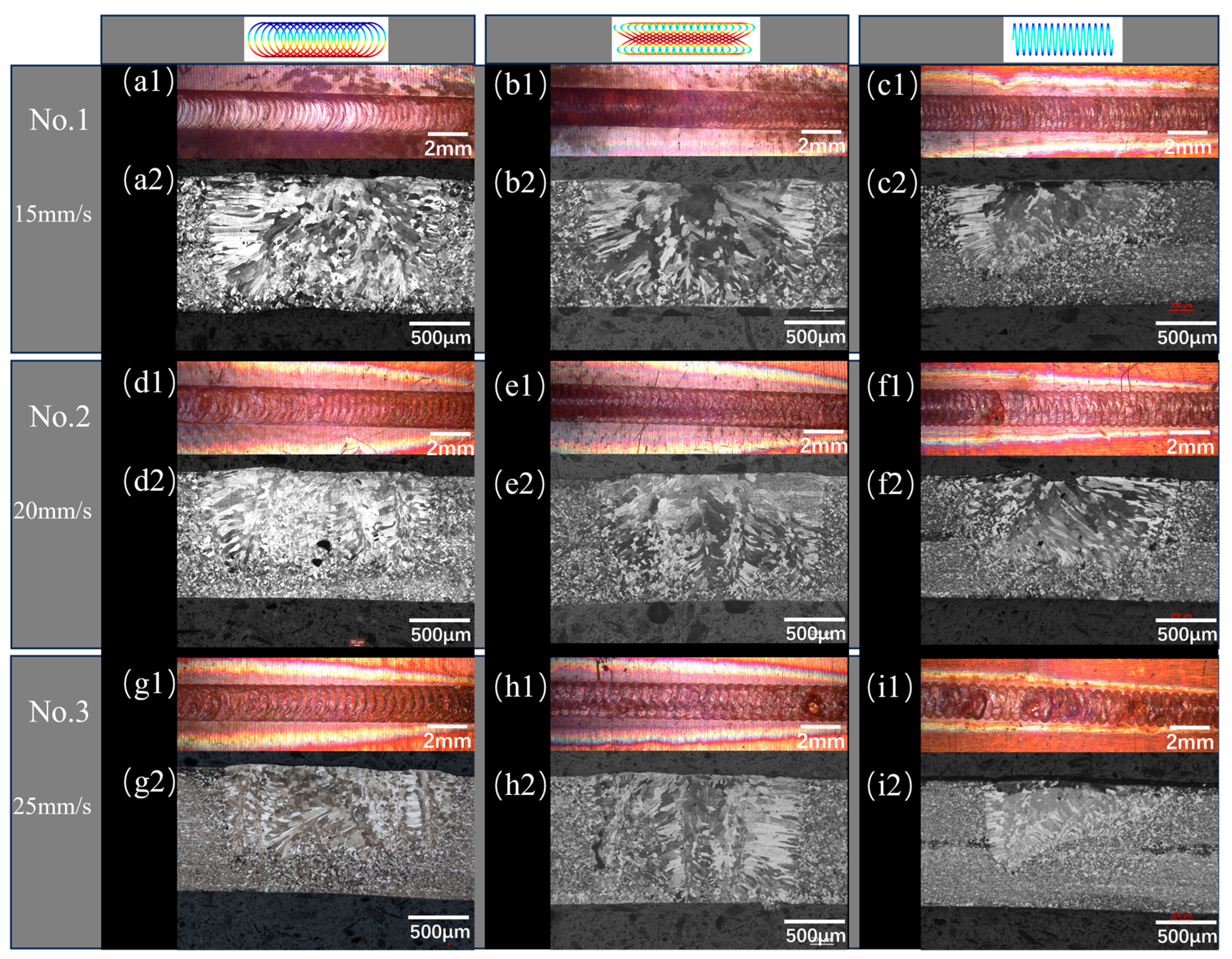
To investigate the influence of the welding process on weld formation, three common oscillation trajectories—circular, 8-shaped, and sinusoidal—were applied in thin-sheet welding [18,19,20,21]. The three welding trajectories were chosen because they represent typical oscillation modes widely used in oscillating laser welding. Circular and 8-shaped paths enhance melt pool stirring and facilitate pore escape, while the sinusoidal path provides a one-dimensional oscillation mode for comparison. This design allows a systematic evaluation of how different oscillation strategies affect energy distribution and weld quality. Figure 4 presents the effects of different welding parameter combinations on the weld surface morphology and cross-sectional profiles. As shown in the figure, the cross-sections of welds under all oscillation modes exhibit a typical U-shaped contour. The fusion width sufficiently covers the intended welding region, providing adequate lateral support to the weld. A smooth transition is observed between the weld toes and the base metal surface, without sharp angles or metal overflow, which significantly reduces stress concentration and enhances crack resistance. Furthermore, the weld surfaces display uniform ripples without evident undercutting, collapse, or spatter, highlighting the advantage of oscillation welding in improving surface quality. Hybrid blue–IR welding has been shown to suppress spatter, aligning with our observations under circular and 8-shaped trajectories [17].
Under the circular welding trajectory Figure 4(a1,a2,d1,d2,g1,g2), the laser energy is symmetrically distributed in a ring-shaped pattern. The resulting weld surface is smooth and exhibits continuous, uniform fish-scale ripples, indicating high-quality weld formation. Owing to the uniform heat input associated with this trajectory, the molten pool expands in a stable manner, producing consistent weld width and penetration depth. At a welding speed of 20 mm·s−1, only a small amount of porosity is observed in the weld. This defect is mainly attributed to the accelerated cooling rate, which hinders the escape of entrapped gases. Consequently, bubbles become trapped during solidification, reducing weld density and potentially compromising mechanical performance. When the welding speed is further increased to 25 mm·s−1, no porosity is detected in the weld cross-section. The higher speed accelerates molten pool solidification, promoting rapid cooling and grain refinement. As a result, the weld microstructure becomes denser, and overall weld quality remains satisfactory.
The 8-shaped trajectory Figure 4(b1,b2,e1,e2,h1,h2) induces periodic oscillatory motion, causing the laser energy to alternately concentrate and disperse across the weld cross-section. The weld surface obtained under this trajectory exhibits a regular texture with distinct fish-scale patterns, yielding a uniform appearance. However, as the welding speed increases, localized regions of the weld show uneven variations in fusion width, with both narrowing and widening observed. This suggests that dynamic changes in welding speed significantly disturb the stability of the molten pool, reducing weld formation quality. At a welding speed of 25 mm·s−1, the overall heat input decreases, sharply lowering molten pool fluidity and accelerating cooling. This rapid solidification severely restricts gas escape from the molten pool, resulting in porosity defects within the weld. Such pores not only reduce weld density but also act as potential crack initiation sites, thereby degrading the mechanical properties and long-term reliability of the welded joint.
In contrast, the weld surface produced under the sinusoidal trajectory Figure 4(c1,c2,f1,f2,i1,i2) exhibits reduced flatness. This trajectory involves high-frequency, small-amplitude reciprocating scanning, which concentrates energy at the turning points and produces a relatively narrow heat-affected zone. At low welding speeds, the penetration depth can reach approximately 50% of the base material thickness. As the welding speed increases, however, penetration depth decreases accordingly. At 20 mm·s−1, a pronounced sagging phenomenon occurs in the central weld region, where the molten metal is pulled downward by the combined effects of gravity and surface tension. This defect originates from the reduced fluidity of the molten pool under high-speed welding, which prevents the molten metal from maintaining a stable profile. The sagging not only disrupts the geometric symmetry of the weld but may also induce stress concentration within the joint, thereby compromising its mechanical performance. With further increases in speed, the shortened energy input time intensifies localized sinking and other unstable molten pool morphologies, ultimately degrading overall weld formation quality. These observations demonstrate that the sinusoidal trajectory is more sensitive to welding speed variations and less capable of producing geometrically stable welds.
In the present study, the shielding gas flow rate was fixed at 15 L/min to isolate the effects of welding speed and oscillation trajectory. We note, however, that welding speed and shielding-gas dynamics are coupled in practice: variations in traverse speed modify local gas flow patterns (wake and entrainment) and the time the molten pool resides within the protective envelope, which can influence oxidation, spatter, and porosity. Therefore, the observed speed-dependent trends should be interpreted under the fixed-gas condition used here. A systematic study that varies gas flow (e.g., 10, 15, and 20 L/min) in combination with welding speed is recommended for future work; complementary computational fluid dynamics (CFD) modeling would also help quantify the gas–molten-pool interactions.
Figure 5 illustrates the effects of welding parameters on fusion width and penetration depth. All three laser welding trajectories effectively increase the weld fusion width. In oscillating laser welding, the beam no longer moves strictly linearly along the welding direction but instead follows predefined trajectories. This oscillatory motion stirs the molten pool, enhances fluid flow velocity, and enlarges the molten pool size, thereby significantly increasing the fusion width. Among the three trajectories, the circular and 8-shaped paths yield the largest fusion widths of 1966 μm and 1953 μm, respectively, indicating that they produce larger molten pool areas and thus contribute to improved weld quality and mechanical performance.
As welding speed increases, the linear energy density decreases, cooling accelerates, and the keyhole effect weakens, leading to reductions in both penetration depth and fusion width. Specifically, increasing the speed from 15 mm·s−1 to 25 mm·s−1 reduces the energy input per unit length, causing an overall decline in penetration depth and fusion width. However, the influence of oscillation trajectories modulates these trends. For the circular trajectory, the strongest heat concentration occurs at 15 mm·s−1, producing a penetration depth of 968 μm and a fusion width of approximately 1966 μm. At 25 mm·s−1, the penetration depth decreases to 840 μm and the fusion width slightly reduces to 1928 μm, suggesting that the circular trajectory promotes width control in deep penetration mode but offers limited penetration capacity. The 8-shaped trajectory, characterized by the largest oscillation amplitude and longest heat exposure, facilitates more uniform heat diffusion across the weld cross-section. Its penetration depth gradually decreases from 942 μm to 906 μm, while fusion width steadily declines from 1953 μm to 1846 μm, demonstrating an excellent balance between width and depth. In contrast, the sinusoidal trajectory, with the smallest amplitude and shortest dwell time, is the most sensitive to speed variations; at 25 mm·s−1, penetration depth and fusion width decrease to the minimum values of 769 μm and 1611 μm, respectively. This trajectory, however, allows flexible adjustment of weld geometry by optimizing oscillation amplitude and frequency.
The variations in fusion width and penetration depth presented in Figure 5 can be explained by the dynamic response of the molten pool to welding speed and trajectory. At lower speeds, the higher linear energy density promotes deeper penetration and wider fusion through improved keyhole stability and longer molten pool lifetime. At higher speeds, the reduced heat input per unit length shortens the molten pool residence time, resulting in decreased penetration depth. Nevertheless, oscillation trajectories redistribute heat input: the circular and 8-shaped paths deliver more balanced energy diffusion, mitigating reductions in fusion width. In contrast, the sinusoidal trajectory concentrates heat in localized regions and has a shorter dwell time, which accelerates cooling, restricts fluid flow, and produces narrower molten pools.

3.1.2. Energy Distribution of Different Welding Trajectories

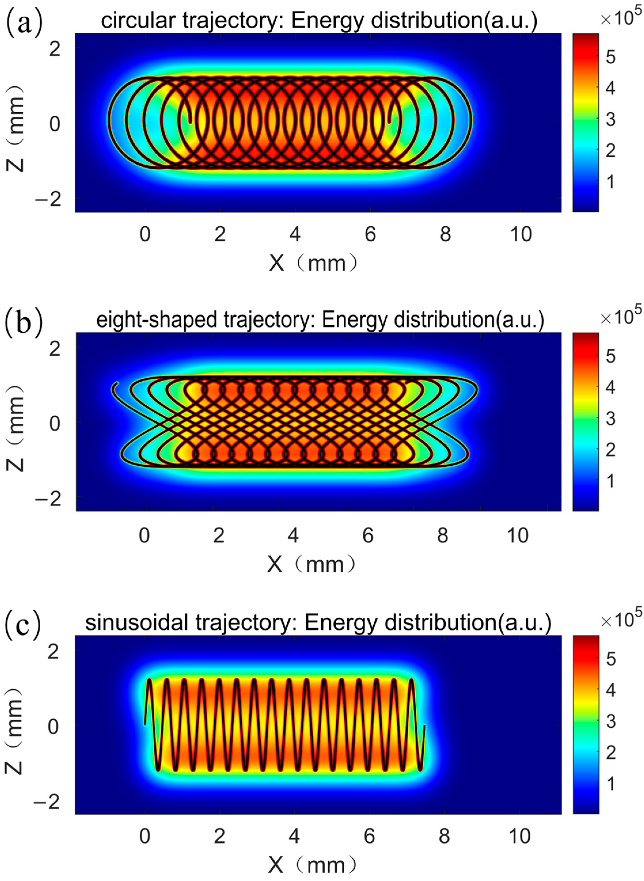
The laser energy distributions under different trajectories are illustrated in Figure 6. The choice of welding trajectory directly governs the spatiotemporal energy distribution within the welding zone. In this study, the circular, 8-shaped, and sinusoidal trajectories exhibit distinct distribution characteristics. The circular trajectory produces a periodic ring-shaped beam path, covering a relatively wide area with uniform heat input. Because the laser beam moves symmetrically around the center, the molten pool receives balanced heating at each moment, resulting in a stable and symmetrical thermal distribution. Consequently, variations in fusion width and penetration depth are minimal, and the weld microstructure remains uniform and consistent.
The 8-shaped trajectory consists of two intersecting loops, yielding a longer beam path as the laser traces the “8” shape. This trajectory induces a periodic cycle of energy concentration and diffusion: when the beam crosses the intersection, the weld zone experiences localized heat concentration, which is subsequently dispersed to surrounding regions. As a result, the 8-shaped trajectory produces a relatively large molten pool and maintains a favorable width-to-depth ratio. Both penetration depth and fusion width remain relatively stable under this trajectory (as shown in Figure 4).
By contrast, the sinusoidal trajectory involves high-frequency, small-amplitude reciprocating motion, with the beam oscillating mainly along the weld centerline. Heat input is concentrated at the turning points of the path, leading to a relatively narrow heated zone. At low welding speeds, both fusion width and penetration depth are limited, reflecting insufficient heat diffusion. At higher speeds, the shortened energy input time exacerbates instability in molten pool morphology, such as localized depressions. Thus, the sinusoidal trajectory produces unstable heat distribution and localized overheating, making it more susceptible to weld defects compared with the circular and 8-shaped paths.
Overall, the circular and 8-shaped trajectories promote a more uniform energy distribution across a wider area, facilitating molten pool expansion and reducing defect formation. In contrast, the sinusoidal trajectory yields a more concentrated energy distribution, resulting in steeper thermal gradients that increase the risk of deformation and defect generation. Detailed analysis of spatial heat input indicates that altering the oscillation trajectory geometry provides an effective means to control the thermal field and, consequently, regulate weld quality.
Different oscillation trajectories therefore exert profound influences on fusion width, penetration depth, and porosity by modifying the spatiotemporal energy distribution. These findings are consistent with previous reports, which indicated that blue-laser preheating enhances fiber-laser absorption and reduces porosity [16]. The sinusoidal trajectory is more suitable for narrow-gap applications, whereas the circular and 8-shaped trajectories show superior performance in balancing fusion width and depth, suppressing porosity, and achieving greater weld stability and consistency. Future research should explore optimization of oscillation frequency and amplitude in circular and 8-shaped trajectories, combined with tailored process parameters, to further improve the quality and reliability of low-power blue–fiber composite laser welding for power module terminals.

3.2. Microstructural Analysis of Weld Seams

During welding, the weld metal undergoes a transition from complete melting to solidification, with microstructural evolution strongly influenced by heat input and cooling rate. In the fusion zone of T2 copper, a single α-phase forms upon solidification, typically exhibiting a mixed distribution of columnar and equiaxed grains. As discussed earlier, welding parameters modulate heat input and thus cooling behavior: increasing welding speed enhances the cooling rate, which suppresses grain growth and promotes refinement.
As shown in Figure 7, changes in welding speed significantly affect grain size and morphology. When the welding speed increases from 15 mm·s−1 to 25 mm·s−1, the heat input per unit length decreases, resulting in noticeable refinement of α-Cu grains in both the weld center and the heat-affected zone (HAZ). The higher cooling rate reduces atomic diffusion, suppressing grain growth and promoting finer equiaxed grains in the weld. This refinement is consistent with the Hall–Petch effect, whereby finer grains enhance hardness and tensile strength. At lower speeds, slower cooling allows the coexistence of both columnar and equiaxed grains, leading to heterogeneous structures. Oscillating trajectories, particularly circular and 8-shaped, further enhance molten pool stirring, which generates additional nucleation sites that suppress columnar grain growth and promote a more uniform distribution of equiaxed grains.
Figure 8 illustrates the influence of welding speed on molten pool flow and microstructure formation, highlighting the regulatory role of speed on molten pool dynamics and grain evolution. At low welding speeds (Figure 8a), the molten pool exhibits a broader geometry with pronounced internal circulation. Slower heat input prolongs the residence time of molten metal, creating a more relaxed thermodynamic environment for solidification. Under these conditions, both equiaxed and columnar grains can grow over a larger scale due to sustained thermal interactions that provide sufficient kinetic conditions for multi-oriented nucleation and growth.
In contrast, at high welding speeds (Figure 8b), the molten pool contracts significantly and the internal flow becomes more compact. The shortened thermal interaction time produces a highly concentrated thermal distribution, restricting equiaxed grain kinetics. At the same time, stronger directional thermal flow along the welding axis promotes preferential growth of columnar grains.
Thus, welding speed has a strong regulatory effect on molten pool behavior and solidification microstructure. At lower speeds (e.g., 15 mm·s−1), higher heat input and slower cooling extend the molten pool lifetime, providing sufficient time for nucleation and crystal growth, which favors multi-oriented equiaxed grains. At higher speeds (e.g., 25 mm·s−1), reduced heat input contracts the molten pool, accelerates cooling, and stabilizes the solidification front, thereby limiting grain growth and favoring columnar grains or textured morphologies. These microstructural trends demonstrate that welding speed, by modifying thermal cycles and solidification conditions, directly regulates grain morphology, orientation, and size distribution, with significant implications for weld mechanical properties and reliability.
Comparing the microstructures under different welding trajectories reveals that oscillating welding enhances molten pool stirring, promoting the generation of more nuclei within the pool. In the weld metal near the fusion line, the microstructure transitions predominantly into columnar grains, which is a typical feature of directional solidification under a steep thermal gradient and rapid cooling conditions [22]. The absence of equiaxed grains indicates insufficient nucleation, leading to preferential grain growth along the direction of heat extraction [23,24,25]. Under circular and 8-shaped trajectories, relatively large equiaxed grain clusters form at the weld center, while columnar grains appear near the edges, resulting in a relatively uniform overall microstructure. This uniformity is attributed to the relatively even heat input and stable solidification conditions provided by these two trajectories, which balance the temperature gradient and solidification rate within the molten pool. In contrast, the sinusoidal trajectory concentrates heat input, creating significant temperature differences between the molten pool center and edges. This leads to abundant equiaxed grains forming in the center, while grains near the pool edges tend to be columnar. The more pronounced variations in temperature gradient and cooling rate along this path result in rapid solidification and fine equiaxed grains at the center. In contrast, slower cooling at the edges allows for the growth of coarser columnar grains, producing an asymmetric grain distribution.
Overall, welding parameters influence grain nucleation and growth by altering the thermal history of the molten pool. In this study, oscillating welding enlarged the weld width and molten pool volume, enhanced internal convection, reduced the solidification rate, and lowered the temperature gradient. These conditions promote the formation of numerous nuclei ahead of the columnar growth front, inhibiting preferential columnar growth while encouraging the formation and expansion of equiaxed grains with random orientation. As a result, oscillating welding produced finer, more uniform microstructures, consistent with experimental observations, and provides theoretical support for microstructural control in copper welds.
Figure 9 further illustrates microstructural characteristics at 25 mm·s−1 under different trajectories. Under the circular trajectory, ring-shaped scanning produces large equiaxed grain clusters at the weld center and columnar grains at the edges (Figure 9a,d). This uniform heat input and stable temperature field allow moderate solidification rates in the center, favoring equiaxed growth and yielding a relatively uniform grain distribution. Under the 8-shaped trajectory, dual-loop oscillation generates higher edge temperatures and relatively lower center temperatures. Consequently, solidification occurs more rapidly in the center, promoting equiaxed grain growth, while steep gradients at the edges promote columnar grains, yielding a mixed equiaxed–columnar structure (Figure 9b,e). Under the sinusoidal trajectory, oscillation is concentrated near the weld center, focusing heat input in this region. The weld center thus experiences the steepest gradients and fastest cooling, producing fine equiaxed grains, while slower cooling near the edges produces coarse columnar grains (Figure 9c,f). Localized overheating and uneven cooling further exacerbate grain distribution asymmetry.
In summary, oscillating welding enhances molten pool flow and nucleation, significantly restricting columnar growth and promoting equiaxed grains. Although this study was limited to T2 copper (0.5 + 0.5 mm), the findings may not directly transfer to brass or other alloys with different thicknesses, as their thermophysical properties and heat flow behaviors differ. Nevertheless, the demonstrated effects of oscillation strategies on energy distribution and defect suppression provide valuable insights for future studies on copper-based alloys of varying thicknesses.

3.3. Mechanical Performance Analysis

3.3.1. Microhardness Analysis

In the experiment, microhardness measurements were conducted on welded joints under different welding speeds. Sampling points were symmetrically taken along the weld centerline at the upper one-third of the weld cross-section. Considering the relatively soft nature of T2 copper, a load of 1 N and a dwell time of 10 s were applied during testing.
As shown in Figure 10, the microhardness distribution across the weld cross-section exhibited a distinct “W”-shaped profile under all oscillation trajectories. The base metal (BM) showed the highest hardness, approximately 100 HV, while the weld center and heat-affected zone (HAZ) exhibited significantly lower hardness values. The minimum hardness (~75 HV) consistently appeared about 1 mm away from the weld centerline, corresponding to the HAZ. This reduction is mainly attributed to grain coarsening caused by elevated temperatures without complete melting, followed by recrystallization during cooling. In contrast, the fusion zone (FZ) and BM exhibited hardness values of around 80 HV and 100 HV, respectively.
Under the circular oscillation trajectory, laser energy is evenly distributed along the ring, and stable convection in the molten pool promotes the formation of fine recrystallized grains in the central region. With increasing welding speed, the energy input per unit length decreases and the cooling rate accelerates, further refining the grains in the FZ and slightly increasing hardness. Simultaneously, hardness fluctuations in the HAZ tend to stabilize. In the case of the 8-shaped trajectory, the periodic superposition of energy produces more complex recirculating flows within the molten pool. As a result, hardness in the central region shows wave-like variations following the oscillation cycle. However, excessive localized heating at the oscillation crossover points induces partial grain coarsening. Increasing the welding speed mitigates this effect by reducing heat accumulation, thereby suppressing excessive fluctuations in the hardness profile. In contrast, under the sinusoidal trajectory, the high-frequency, small-amplitude reciprocating motion narrows the FZ and induces intense, non-uniform thermal cycles, which in turn enlarge the HAZ.
At constant laser power, increasing the welding speed reduces overall heat input, leading to further grain refinement and an overall increase in weld hardness. The hardness valley gradually shifts upward and becomes more uniform. These results demonstrate that higher welding speed not only reduces grain size but also improves the homogeneity of hardness distribution. The significant hardness increase observed in the weld center is consistent with the Hall–Petch relationship, which states that finer grains result in higher hardness.

3.3.2. Tensile Property Analysis

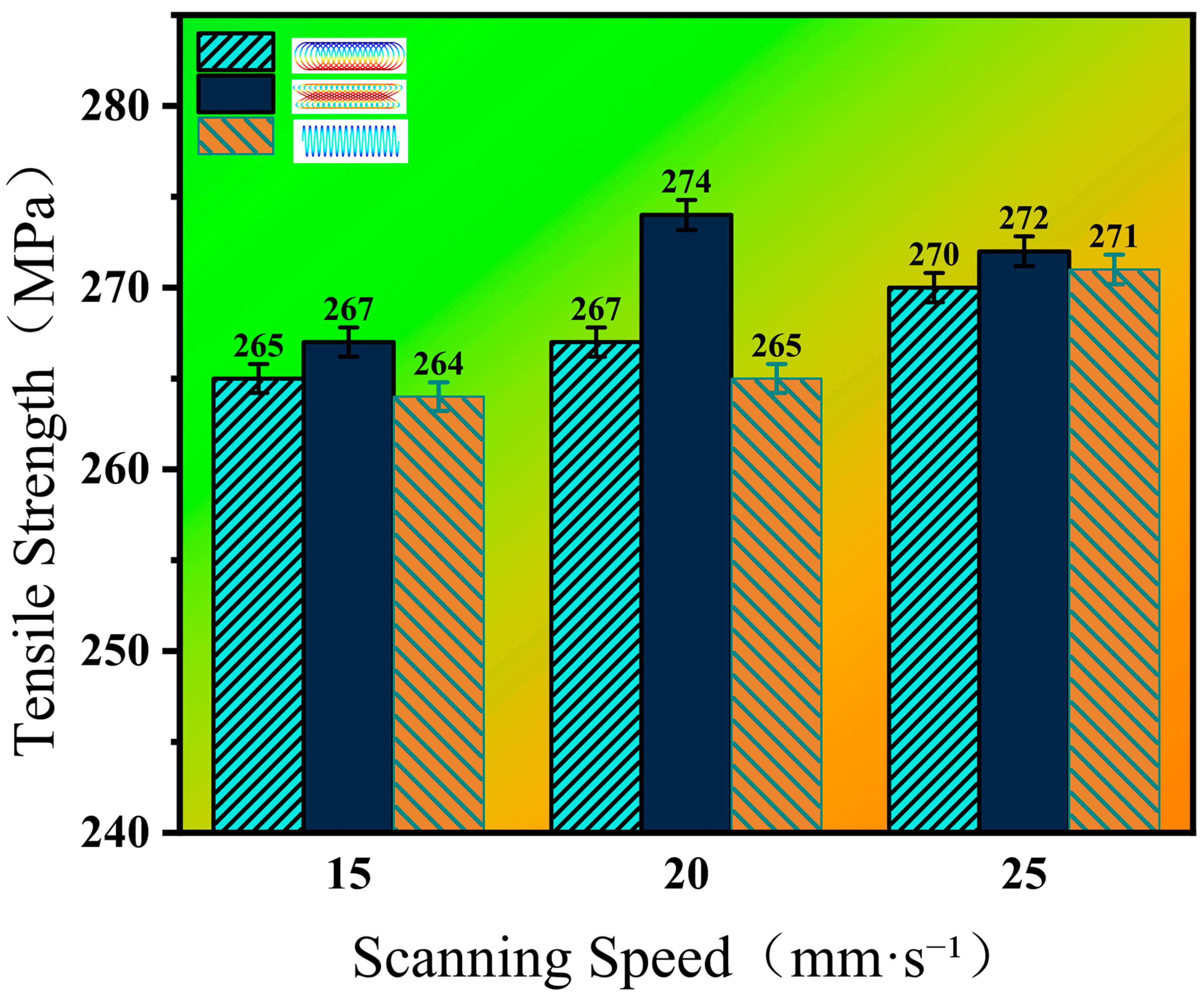
The tensile strength of welded joints under different parameters is presented in Figure 11. With increasing welding speed, the tensile strength of the joints consistently improves. All fractures occurred near the fusion line of the weld. Experimental results show that at a welding speed of 25 mm·s−1, the tensile strength of specimens for all oscillation trajectories exceeded 270 MPa. Among them, the 8-shaped trajectory achieved the highest strength, approximately 274 MPa, at 20 mm·s−1.
Compared with the circular and sinusoidal trajectories, the 8-shaped trajectory demonstrated both higher strength levels and greater consistency across different welding speeds, indicating a denser internal weld structure. This improvement can be attributed to the relatively uniform heat input and enhanced molten pool stirring provided by the circular and 8-shaped oscillation paths, which effectively suppress the formation of porosity and other defects. Consequently, weld density and continuity were improved, leading to superior mechanical performance.
In summary, grain refinement in the weld zone is a key factor governing tensile strength. Finer grains correlate with enhanced mechanical properties, consistent with the Hall–Petch effect.

4. Conclusions

In this study, the effects of welding trajectory and speed on the weld formation and mechanical properties of 0.5 mm T2 copper joints under hybrid blue–fiber laser welding were systematically investigated. Based on the experimental results, the following conclusions can be drawn:
  • All three welding trajectories (circular, 8-shaped, and sinusoidal) effectively improved the weld width. Compared with conventional linear welding, the oscillating trajectories significantly optimized weld formation quality by enhancing molten pool stirring and expanding the heat input area. Among them, the circular and 8-shaped trajectories exhibited more uniform energy distribution, leading to better width-to-depth ratios and higher weld stability than the sinusoidal trajectory.
  • Dependency of speed and fusion characteristics: Increasing welding speed reduces linear energy input, which leads to a decrease in both penetration depth and fusion width. At the same time, higher speeds accelerate cooling, promote grain refinement, and improve hardness and tensile strength. Excessive speed, however, may induce porosity due to insufficient time for gas escape.
  • Dependency of trajectory and energy distribution: Different oscillation trajectories redistribute laser energy within the molten pool. The circular and 8-shaped paths produce more uniform energy diffusion, resulting in stable molten pool dynamics, suppression of porosity, and balanced width-to-depth ratios. Compared with the other trajectories, the sinusoidal path is more sensitive to changes in welding speed and is more likely to generate localized defects.
  • Dependency of microstructure and mechanical performance: Microstructural evolution is directly linked to the interplay of speed and trajectory. Faster cooling and stronger oscillation-induced stirring increase nucleation density, suppress columnar growth, and promote equiaxed grain formation. These refined and homogenized microstructures correlate with higher hardness and superior tensile strength, consistent with the Hall–Petch relationship.
  • Overall assessment: For low-power hybrid blue–fiber laser welding of thin T2 copper terminals, the circular trajectory provides the most consistent weld geometry and hardness distribution, while the 8-shaped trajectory achieves the highest tensile strength due to its favorable balance of energy input and molten pool stability. The sinusoidal trajectory may still be useful for narrow-gap applications, though with reduced robustness.
Limitations and future work: The present work is limited to 0.5 mm thick T2 copper. Future studies should consider scaling to different thicknesses and copper-based alloys, as well as additional characterizations such as electrical conductivity and long-term service reliability, to further validate the parameter–property relationships established here.

Author Contributions

Conceptualization, M.Y. and Y.K.; methodology, X.W. and N.Q.; software, X.W.; validation, X.W., N.Q., S.L. and Q.L.; formal analysis, X.W.; investigation, X.W. and Q.L.; resources, Y.K. and M.J.; data curation, Q.F.; writing—original draft preparation, X.W.; writing—review and editing, M.Y. and Y.K.; visualization, Q.L. and Q.F.; supervision, M.Y. and Y.K.; project administration, M.Y.; funding acquisition, Y.K. All authors have read and agreed to the published version of the manuscript.

Funding

This research received no external funding.

Data Availability Statement

The data are not publicly available due to institutional confidentiality. Data may be provided by the corresponding author upon reasonable request and organizational approval.

Conflicts of Interest

Author Na Qi was employed by the company Shanghai Aerospace Equipments Manufacturer Co., Ltd. Author Shengxiang Liu was employed by the company Heilongjiang Construction & Installation Group Co., Ltd. The remaining authors declare that the research was conducted in the absence of any commercial or financial relationships that could be construed as a potential conflict of interest.

References

  1. Haubold, M.; Ganser, A.; Eder, T.; Zäh, M.F. Laser Welding of Copper Using a High Power Disc Laser at Green Wavelength. Procedia CIRP 2018, 74, 446–449. [Google Scholar] [CrossRef]
  2. Kaufmann, F.; Forster, C.; Hummel, M.; Olowinsky, A.; Beckmann, F.; Moosmann, J.; Roth, S.; Schmidt, M. Characterization of Vapor Capillary Geometry in Laser Beam Welding of Copper with 515 Nm and 1030 Nm Laser Beam Sources by Means of In Situ Synchrotron X-Ray Imaging. Metals 2023, 13, 135. [Google Scholar] [CrossRef]
  3. Pavliček, N.; Mohn, F. Laser bonding of copper ribbons and clips on SiC power MOSFETs with sintered copper bond buffers. In Proceedings of the 2020 IEEE 8th Electronics System-Integration Technology Conference (ESTC), Vestfold, Norway, 15–18 September 2020; pp. 1–4. [Google Scholar]
  4. Xu, T.; Wang, L.; Ma, X.; Zhu, Z.; Wang, C.; Mi, G. Solidification Sequence and Crystal Growth during Laser Welding Stainless Steel to Copper. Mater. Des. 2023, 225, 111519. [Google Scholar] [CrossRef]
  5. Chatterjee, S.; Trinh, L.N.; Lee, D. Mechanical and Microstructural Investigation of Dissimilar Joints of Al-Cu and Cu-Al Metals Using Nanosecond Laser. J. Mech. Sci. Technol. 2022, 36, 4205–4211. [Google Scholar] [CrossRef]
  6. Kim, H.-T.; Yoon, J.-W. Microstructures and Mechanical Properties of Ultrasonic-Welded Cu–Cu Joints for Power Module Terminals in Electric Vehicles. J. Mater. Sci. Mater. Electron. 2023, 34, 1997. [Google Scholar] [CrossRef]
  7. Biro, E.; Weckman, D.C.; Zhou, Y. Pulsed Nd:YAG Laser Welding of Copper Using Oxygenated Assist Gases. Met. Mater. Trans. A 2002, 33, 2019–2030. [Google Scholar] [CrossRef]
  8. Wang, L.; Gao, M.; Zhang, C.; Zeng, X. Effect of Beam Oscillating Pattern on Weld Characterization of Laser Welding of AA6061-T6 Aluminum Alloy. Mater. Des. 2016, 108, 707–717. [Google Scholar] [CrossRef]
  9. Dimatteo, V.; Ascari, A.; Faverzani, P.; Poggio, L.; Fortunato, A. The Effect of Process Parameters on the Morphology, Mechanical Strength and Electrical Resistance of CW Laser-Welded Pure Copper Hairpins. J. Manuf. Process. 2021, 62, 450–457. [Google Scholar] [CrossRef]
  10. Arjmand, E.; Spann, T.; Madloch, S. Development of Cu-Cu Joining Technology by Laser Welding for Terminal Attach within Power Semiconductor Package. In Proceedings of the PCIM Europe 2023; International Exhibition and Conference for Power Electronics, Intelligent Motion, Renewable Energy and Energy Management, Nuremberg, Germany, 9–11 May 2023; VDE: Berlin, Germany, 2023; pp. 1–7. [Google Scholar]
  11. Alter, L.; Heider, A.; Bergmann, J.-P. Investigations on Copper Welding Using a Frequency-Doubled Disk Laser and High Welding Speeds. Procedia CIRP 2018, 74, 12–16. [Google Scholar] [CrossRef]
  12. Chung, W.-S.; Olowinsky, A.; Gillner, A. Process Studies on Copper Laser Beam Welding over Gap by Using Disc Laser at Green Wavelength. J. Adv. Join. Process. 2020, 1, 100009. [Google Scholar] [CrossRef]
  13. Cai, H.; Zhou, J.; Zhang, S.; Jia, P. Effect of Red-Blue Composite Laser Welding Joint on Microstructure and Properties of Copper Alloy. Int. Core J. Eng. 2024, 10, 182–190. [Google Scholar]
  14. Yang, H.; Tang, X.; Hu, C.; Liu, S.; Fan, Y.; Xiao, Y.; Lu, G.; Wang, Q.; Chen, G.; Xing, P.; et al. Study on Laser Welding of Copper Material by Hybrid Light Source of Blue Diode Laser and Fiber Laser. J. Laser Appl. 2021, 33, 032018. [Google Scholar] [CrossRef]
  15. Fujio, S.; Sato, Y.; Takenaka, K.; Ito, R.; Ito, M.; Harada, M.; Nishikawa, T.; Suga, T.; Tsukamoto, M. Welding of Pure Copper Wires Using a Hybrid Laser System with a Blue Diode Laser and a Single-Mode Fiber Laser. J. Laser Appl. 2021, 33, 042056. [Google Scholar] [CrossRef]
  16. Wu, D.; Sun, J.; Li, Z.; Huang, J.; Feng, K. Molten Pool Behaviors and Energy Absorption in Coaxial Hybrid Blue-IR Lasers Welding of a Copper Material. Int. J. Therm. Sci. 2023, 184, 107945. [Google Scholar] [CrossRef]
  17. Fujio, S.; Sato, Y.; Sudo, M.; Takenaka, K.; Tojo, K.; Pasang, T.; Tsukamoto, M. Spatter Reduction in Deep Penetration Welding of Pure Copper Using Blue-IR Hybrid Laser. Weld. World 2024, 68, 1515–1524. [Google Scholar] [CrossRef]
  18. Jiang, N.; Jiang, M.; Chen, X.; Han, T.; Ma, S.; Chen, Y.; Wang, Z.; Jiang, Y.; Yang, L.; Lei, Z.; et al. Effect of Beam Oscillation on Weld Formation, Microstructure and Mechanical Properties in Vacuum Laser Beam Welding of Thick Section 5083 Aluminum Alloy. Opt. Laser Technol. 2024, 171, 110408. [Google Scholar] [CrossRef]
  19. Mahrle, A.; Beyer, E. Modeling and Simulation of the Energy Deposition in Laser Beam Welding with Oscillatory Beam Deflection. In Proceedings of the International Congress on Applications of Lasers & Electro-Optics, Orlando, FL, USA, 29 October–1 November 2007; Laser Institute of America: Orlando, FL, USA; p. 1805. [Google Scholar] [CrossRef]
  20. Prieto, C.; Vaamonde, E.; Diego-Vallejo, D.; Jimenez, J.; Urbach, B.; Vidne, Y.; Shekel, E. Dynamic laser beam shaping for laser aluminium welding in e-mobility applications. Procedia CIRP 2020, 94, 596–600. [Google Scholar] [CrossRef]
  21. Zhang, M.; Wang, C.; Mi, G.; Jiang, P.; Zhang, X.; Yan, X. Laser Beam Oscillation Welded SiCp/2xx Al Alloy: Microstructure, Phase Interface and Mechanical Properties. Mater. Sci. Eng. A 2021, 820, 141482. [Google Scholar] [CrossRef]
  22. Greebmalai, J.; Sadasue, S.; Marumoto, K.; Warinsiriruk, E.; Yamamoto, M. Weld Formation and Characteristics of Hot-Wire Laser Welding in Aluminum Alloy Narrow-Gap Joints. Metals 2025, 15, 809. [Google Scholar] [CrossRef]
  23. Faye, A.; Balcaen, Y.; Lacroix, L.; Alexis, J. Effects of welding parameters on the microstructure and mechanical properties of the AA6061 aluminium alloy joined by a Yb: YAG laser beam. J. Adv. Join. Process. 2021, 3, 100047. [Google Scholar] [CrossRef]
  24. Kang, S.G.; Shin, J. The effect of laser beam intensity distribution on weld characteristics in laser welded aluminum alloy (AA5052). Opt. Laser Technol. 2021, 142, 107239. [Google Scholar] [CrossRef]
  25. Pang, X.; Dai, J.; Chen, S.; Zhang, M. Microstructure and Mechanical Properties of Fiber Laser Welding of Aluminum Alloy with Beam Oscillation. Appl. Sci. 2019, 9, 5096. [Google Scholar] [CrossRef]
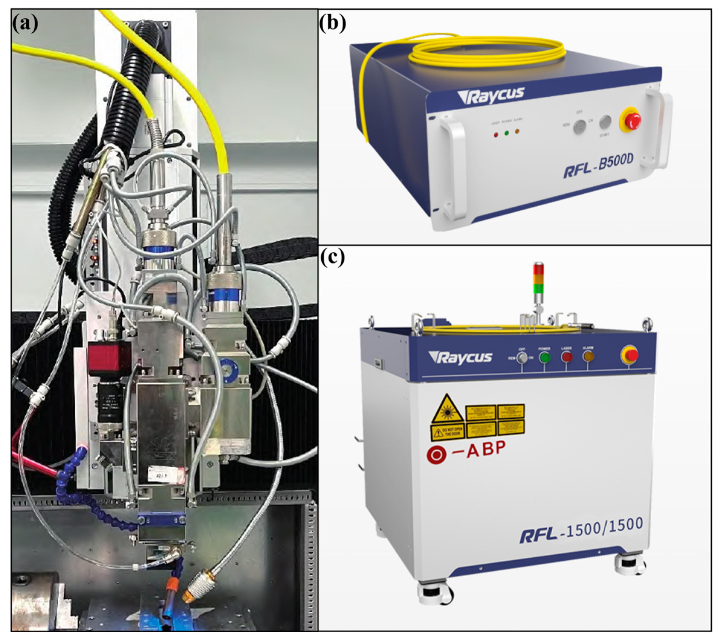
Figure 1. Blue laser–fiber laser hybrid welding system: (a) hybrid laser welding head; (b) RFL-B500D blue laser; (c) RFL-1500/1500 fiber laser with adjustable beam mode.
Metals 15 01058 g001
Figure 2. Schematic diagram of the fiber–blue laser hybrid welding process.
Metals 15 01058 g002
Figure 3. Schematic diagrams of welding paths: (a) circular (O-shaped); (b) 8-shaped; (c) sinusoidal.
Metals 15 01058 g003
Figure 4. Weld surface appearances and cross-sectional profiles of the weld joints under three oscillating trajectories: (a1,a2,d1,d2,g1,g2) circular, (b1,b2,e1,e2,h1,h2) 8-shaped, and (c1,c2,f1,f2,i1,i2) sinusoidal.
Metals 15 01058 g004
Figure 5. Effects of welding parameters on (a) fusion width and (b) penetration depth.
Metals 15 01058 g005
Figure 6. Laser energy distribution under different trajectories: (a) circular trajectory, (b) 8-shaped trajectory, and (c) sinusoidal trajectory.
Metals 15 01058 g006
Figure 7. Microstructure at the weld center with circular trajectory: (a) 15 mm·s−1, (b) 20 mm·s−1, (c) 25 mm·s−1.
Metals 15 01058 g007
Figure 8. Schematic diagram of the effect of molten pool flow on microstructure formation at different welding speeds. (a) Slow speed. (b) High speed.
Metals 15 01058 g008
Figure 9. Microstructure morphology of weld seams under different welding trajectories at a welding speed of 25 mm·s−1. (a) Circular trajectory. (b) 8-shaped trajectory. (c) Sinusoidal trajectory. (d) Weld center area of circular trajectory. (e) Weld center area of 8-shaped trajectory. (f) Weld center area of sinusoidal trajectory.
Metals 15 01058 g009
Figure 10. Microhardness distribution of welded joints under different welding trajectories: (a) circular trajectory; (b) 8-shaped trajectory; (c) sinusoidal trajectory.
Metals 15 01058 g010
Figure 11. Tensile strength of joints at different welding speeds for samples welded with various oscillation trajectories.
Metals 15 01058 g011
Table 1. Chemical composition of T2 copper (mass fraction, %).
CuFeSPbAsSbBi
>99.90.0050.0050.0050.0020.0020.001
Table 2. Key parameters of the blue laser and the fiber laser.
LaserMax. Power
P/KW
Core Diameter
Dc/μm
Wavelength
λ/nm
RFL-1500/1500
RFL-B500D
1.5
0.5
50
400
1080
445
Table 3. Laser welding experimental process parameters.
Welding TrajectoryBlue Laser Power
Pblue/W
Fiber Laser Power
Pfiber/W
Welding Speed
V/ mm·s−1
Defocus
Δ(mm)
Circular
8-shaped
Sinusoidal
30060015, 20, 250
Disclaimer/Publisher’s Note: The statements, opinions and data contained in all publications are solely those of the individual author(s) and contributor(s) and not of MDPI and/or the editor(s). MDPI and/or the editor(s) disclaim responsibility for any injury to people or property resulting from any ideas, methods, instructions or products referred to in the content.