Article

Harnessing Hydrothermal Treatments to Control Magnesium Alloy Degradation for Bioresorbable Implants: A Comprehensive Evaluation of Bath Chemistry Effect

1
BioSurf Lab., Department of Chemistry, Materials and Chemical Engineering “G. Natta”, Politecnico di Milano, 20133 Milan, Italy
2
National Interuniversity Consortium of Materials Science and Technology (INSTM), Local Unit Politecnico di Milano, 20133 Milan, Italy
*
Author to whom correspondence should be addressed.
Metals 2025, 15(9), 1056; https://doi.org/10.3390/met15091056
Submission received: 14 August 2025 / Revised: 16 September 2025 / Accepted: 19 September 2025 / Published: 22 September 2025
(This article belongs to the Special Issue Recent Advances in Surface Modification of Metallic Materials)

Abstract

Magnesium alloys have been recently recognized as promising materials for temporary orthopedic applications, thanks to their biocompatibility, nontoxicity and biodegradability, combined with bone-like mechanical properties; nevertheless, their clinical viability is still hindered by their excessively rapid corrosion in physiological environments. In this context, hydrothermal surface modification offers a simple and inexpensive option to form thick ceramic conversion films capable of protecting magnesium and delaying the initial stages of corrosion. In this study, magnesium samples were hydrothermally treated in various aqueous baths to systematically assess the influence of their chemistry on the resulting coating features. The obtained coatings were characterized in terms of physicochemical properties, electrochemical corrosion behavior in SBF, and long-term degradation with volumetric loss quantification by µ-CT. The results highlighted how corrosion resistance is dictated by coating uniformity rather than thickness. Moreover, XRD analyses revealed that all the best-performing coatings contained a stable magnesium oxide phase in addition to magnesium hydroxide, a feature absent in less protective films. A simple sodium nitrate solution was found to produce the most protective layer, showing the lowest volumetric losses after immersion testing.

1. Introduction

Clinical management of bone fractures, particularly in orthopedic trauma surgery, relies heavily on internal fixation. This approach utilizes metallic devices such as plates, screws, nails, and wires to stabilize fractured segments, maintain anatomical alignment, and create an environment with mechanical properties that are conducive to bone healing [1,2]. For decades, the materials of choice for these temporary fixation devices have been bio-inert metals, predominantly medical-grade stainless steel (e.g., 316L) and titanium alloys (e.g., Ti-6Al-4V). These materials have become the clinical standard due to their well-established biocompatibility, high mechanical strength, and excellent corrosion resistance, which ensure their structural reliability throughout the critical bone consolidation period [2,3]. However, the bio-inertness and intrinsic stability that make these materials reliable, in the case of temporary devices make it necessary to perform additional surgeries to remove the implant once healing is complete. While often considered a minor intervention, implant removal surgery is associated with a considerable range of potential complications, patient morbidity, and healthcare costs [4,5,6]. Documented risks include infection, with rates reported between 2% and 10%, damage to adjacent nerves and blood vessels, post-operative pain, and the potential for re-fracture through screw holes or at the site of plate removal. Furthermore, this secondary procedure places an additional burden on healthcare systems, requiring operating room time, surgical staff, and anesthesia, all of which contribute to increased costs [4].
In the search for alternatives to conventional bio-inert metals, a new class of materials—biodegradable metals—has garnered significant scientific and clinical interest [7]. Among these, magnesium (Mg) and its alloys have emerged as promising candidates for temporary orthopedic implants. Unlike steel or titanium, magnesium is a metabolically active element. It is the fourth most abundant cation in the human body and an essential cofactor in over 300 enzymatic reactions, playing a crucial role in bone metabolism and structural integrity of the mineralized matrix [8]. This inherent biocompatibility ensures that the degradation products of a magnesium implant, primarily Mg2+ ions, are not only non-toxic, but can be safely metabolized and utilized by the body. Indeed, numerous studies have demonstrated that the local release of magnesium ions can stimulate osteoblast proliferation and differentiation, actively promoting new bone formation at the implant site [9,10,11]. Moreover, from a mechanical standpoint, magnesium alloys possess properties that are highly favorable for fracture fixation. Their density is much closer to that of human bone compared to steel or titanium, and their lower elastic modulus allows for more physiological load sharing between the implant and the healing bone, which is beneficial for the remodeling process [11,12]. These biological and mechanical advantages position magnesium as a potentially superior material for temporary devices.
However, the clinical translation of magnesium alloys is hindered by their extreme chemical reactivity and consequent rapid corrosion rate in the chloride-rich physiological environment of the human body [13,14]. This phenomenon causes a rapid loss of the implant’s mechanical integrity, potentially leading to its premature failure, while also locally generating a significant volume of hydrogen gas. If the rate of gas evolution surpasses the body’s capacity for diffusion and transport, gas can accumulate in subcutaneous pockets, causing tissue delamination, inflammation, and patient discomfort [15]. Moreover, the formation of magnesium hydroxide (Mg(OH)2) results in a localized increase in pH, an alkalization of the microenvironment that can be cytotoxic and detrimental to tissue function if not adequately buffered by physiological systems [16].
Metallurgical strategies, such as high-purity processing and alloying, have already been exploited to improve magnesium corrosion resistance with the purpose of addressing these limitations [17,18]; however, surface modification represents a more direct, versatile, and often economic approach to temporarily protect the material [19,20]. The objective of surface engineering is to create a stable, protective barrier layer at the interface between the reactive Mg substrate and the aggressive biological environment, thereby slowing the initial corrosion cascade without altering the desirable bulk mechanical properties of the substrate and its intrinsic degradability. A wide variety of surface modification techniques have been explored, including chemical conversion coatings (e.g., phosphate or fluoride-based), anodization, micro-arc oxidation, and the deposition of polymer or ceramic layers [21]. Among these, conversion coatings, which are formed in situ by chemically transforming the surface of the magnesium itself, are particularly advantageous due to their intrinsically strong adhesion to the substrate.
Of the several available conversion coating processes for magnesium and its alloys, hydrothermal treatments have gained significant traction due to their simplicity, low cost, environmental friendliness, and scalability [22,23]. The technique involves immersing the Mg alloy in a selected aqueous solution within a sealed autoclave and heating it to a moderate temperature (typically 100–200 °C). The resulting autogenous pressure and elevated temperature allow the solvent to reach a pressurized vapor state, facilitating the diffusion of ionic species from the solution towards the metal surface and thus enabling the growth of a dense, crystalline, and well-adhered coating [24]. A key advantage of the hydrothermal method is its exceptional versatility. By simply changing the chemical composition of the aqueous precursor solution, composition, morphology, and functional properties of the resulting coating can be precisely tuned. For instance, treatment in pure water primarily forms a layer of magnesium hydroxide (Mg(OH)2) [25], but the inclusion of other ions allows for the creation of more complex, multifunctional coatings [23,26]. The addition of phosphate and calcium ions can lead to the formation of osteoconductive calcium phosphate (CaP) phases, while carbonate ions can produce biocompatible carbonate layers [27,28,29]. This offers a powerful platform for creating surfaces that not only resist corrosion but may also enhance the biological response to the implant.
Despite being considered really promising, a comprehensive and systematic understanding of how different solution chemistries affect the properties and performance of hydrothermal coatings on Mg alloys is still lacking. Much of the existing literature focuses on a narrow range of solutions or process parameters. Therefore, a broad, comparative investigation is required to establish the fundamental principles for designing effective hydrothermal treatments. In this context, the present study aims to provide a systematic and comparative evaluation of hydrothermal treatment processes applied to magnesium. A broad library of aqueous solution formulations—comprising carbonates, various phosphates, calcium-containing salts, nitrates, and other functional compounds—was employed under consistent processing parameters to investigate their influence on coating formation. After an initial screening for coating quality, the most promising formulations were selected for in-depth characterization, including morphological, compositional, wettability, electrochemical, and long-term degradation assessments. This work seeks to establish a clearer understanding of how solution chemistry influences the corrosion protection and potential bioactivity of hydrothermally treated coatings, ultimately contributing to the development of clinically viable biodegradable Mg-based orthopedic implants.

2. Materials and Methods

2.1. Materials and Sample Preparation

The substrate material used throughout this study was an AZ31B magnesium alloy (certified composition: 95.25 wt% Mg, 2.98 wt% Al, 1.03 wt% Zn, 0.50 wt% Mn and balance Fe, Si, Ca, Cu, Ni), provided in the form of a 0.5 mm thick commercial sheets (RL3, Italy). The sheet was mechanically cut into rectangular specimens of two different sizes: 20 × 30 mm for electrochemical tests and macroscopic evaluation, and 10 × 15 mm for all other characterizations and degradation tests.
Prior to hydrothermal treatment, all samples underwent a standardized surface pre-treatment protocol to ensure their cleanliness and reactivity. This involved a 10-s acid etching step by immersion in a solution composed of 1M nitric acid (HNO3) and 4M acetic acid (CH3COOH). Following etching, the samples were immediately rinsed twice with deionized water and then cleaned in an ultrasonic bath for 5 min to remove any residual acid or loosely adhered surface contaminants. All samples were then dried with compressed air to limit any spontaneous oxidation.

2.2. Hydrothermal Treatment Protocol

Hydrothermal treatments were conducted in 100 mL capacity Teflon-lined stainless steel autoclaves (HUANYU, Hangzhou Songhai Electronic Technology, Hangzhou, China). For each treatment, the Teflon liner was filled up to 75% of its volume (75 mL) with the desired aqueous solution. The pre-treated AZ31B samples were placed inside the liner, supported by a custom-made Teflon holder to prevent contact among samples and between samples and the vessel walls.
The sealed autoclaves were then placed in a thermostatic oven. A fixed treatment protocol was used for all experiments: the temperature was gradually increased, starting from room temperature with a heating rate of 4.5 °C/min, up to a final temperature of 160 °C. The total treatment time was of 4 h and 30 min. After the treatment, the oven was switched off, and the autoclaves were allowed to cool naturally back to room temperature. The samples were then retrieved, rinsed thoroughly with deionized water to remove any non-adherent precipitates, and dried with compressed air.
A wide range of aqueous solutions was prepared using analytical grade reagents (Sigma Aldrich, St Louis, MO, USA) and deionized water. Tested concentrations were selected based on preliminary treatments and optimization to maximize additives’ incorporation in the resulting conversion layers, while limiting their possible detrimental effect on coating quality. The chemicals and respective molar concentrations used to prepare each solution are detailed in Table 1. A control sample, referred to as ACQ, was prepared using only deionized water [25].

2.3. Coating Characterization

Macroscopic observation and thickness evaluation. After treatment, all samples were visually inspected and photographed to assess coating uniformity and possible presence of macroscopic defects or fouling. The thickness of the coatings was then measured in a non-destructive way using a DUALSCOPE FMP100 eddy current gauge (Helmut Fischer, Sindelfingen, Germany) equipped with a probe suitable for non-ferromagnetic substrates, according to ISO 2360. For each sample, 30 measurements were taken randomly on each side (total of 60 measurements) to calculate the average thickness and evaluate its uniformity.
Surface and structural analysis. Surface morphology and cross-sectional structure of the coatings were examined using a tabletop Scanning Electron Microscope (SEM), model EM-30C (COXEM, Daejeon, Republic of Korea). Images were acquired using secondary electrons at various magnifications. The elemental composition of the surfaces was analyzed using an integrated Energy Dispersive X-ray Spectroscopy (EDS) detector (XFlash 6-30, Bruker, Karlsruhe, Germany). The crystalline phases present in the coatings were identified by X-Ray Diffraction (XRD, Empyrean, Malvern Panalytical, Malvern, Worcestershire, United Kingdom). XRD patterns were collected over a 2θ range of 5° to 70° using Cu Kα radiation. Phase identification was performed by matching the diffraction peaks with entries in the crystallographic database.
Wettability measurement. Wettability of the coatings’ surfaces was evaluated by a TBU 95 optical contact angle goniometer (DataPhysics Instruments, Filderstadt, Germany). A 2 µL droplet of deionized water was dispensed onto the surface, and the static contact angle (SCA) was measured on both the left and right sides of the droplet. The procedure was repeated on three different samples for each coating type, and the average contact angle was calculated.

2.4. Corrosion/Degradation Assessment

Electrochemical corrosion evaluation. Short-term corrosion behavior was assessed by potentiodynamic polarization (PDP) using an Autolab PGSTAT30 potentiostat/galvanostat (Metrohm, Herisau, Switzerland) in a standard three-electrode cell. The coated sample, with a defined exposed area of 10 × 10 mm2, served as the working electrode. A platinum mesh and a silver/silver chloride (SSC) electrode were used respectively as the counter and reference electrodes. The electrolyte was 500 mL of Simulated Body Fluid (SBF), prepared as per the protocol of Kokubo and Takadama [30] and kept at a constant temperature of 37 °C. After stabilizing at the open circuit potential (OCP) for 20 min, a potentiodynamic scan was performed from −0.5 V to +1.0 V relative to the OCP at a scan rate of 1 mV/s. The corrosion potential (Ecorr) and corrosion current density (icorr) were determined from the resulting Tafel plots using the Tafel extrapolation method. The corrosion rate (CR, in mm/year) and estimated polarization resistance (Rpol) were also estimated via the NOVA 2.1.5 software.
In vitro degradation and volumetric loss analysis. Long-term degradation was evaluated via static immersion tests. Six samples of each selected coating type were immersed in Dulbecco’s Phosphate-Buffered Saline (PBS, Sigma Aldrich, St Louis, MO, USA) and kept at a constant temperature of 37 °C. The degradation was monitored at 1, 7, and 14 days of incubation via nondestructive analyses. The surface morphology and composition were re-examined using SEM/EDS. The volumetric loss due to corrosion was quantified using a SkyScan 1275 desktop micro-computed tomography (µ-CT) system (Bruker, Karlsruhe, Germany). The samples were scanned, and the resulting projection images were reconstructed into 3D models using the NRecon v2.0 software. The volume of each sample at each timepoint was calculated from the 3D models using the VGStudio 2023.1 software (Volume Graphics, Heidelberg, Germany), allowing for the determination of percentage sample volume reduction over time. The corrosion rate of the analyzed samples (CR, in mm/year) was then estimated using the following equation:
CR = (∆Vt/A) × (365/t)
where ∆Vt is the volume variation of the sample at the selected timepoint (as obtained by µ-CT, in mm3), A is the total sample surface area (in mm2), and t is the timepoint (in days).

2.5. Statistics

For all the quantitative data presented in this work, statistical significance was assessed via OriginPro 2023 (OriginLab, Northampton, MA, USA) by one-way ANOVA and post hoc Tukey’s HSD tests after data normality verification through Shapiro–Wilk test; differences with p-values lower than 0.05 were considered statistically significant. Error bars in graphs correspond to mean values ± standard deviations.

3. Results

3.1. Hydrothermal Coatings Screening

The initial screening based on macroscopic observation was crucial for identifying viable coatings. As shown in Figure 1, coatings obtained from several solutions (NBDS, Ca2BDS, CaDAP, CeN and CuN) resulted in grossly non-uniform surfaces, characterized by heavy, poorly adhered precipitates and fouling. These were deemed unsuitable for providing consistent protection and thus were excluded from further studies. In contrast, many other solutions produced visually homogeneous and consistent coatings. Among these, the DAP systems were particularly notable for their uniform, crystalline, and clean appearance. Other surfaces, mainly grown in carbonate-based systems (such as BDS and Ca2BDS), showed a high visual inhomogeneity, possibly related to the incidence of low soluble compounds’ precipitation during the high temperature treatment.
The coating thickness measurements, summarized in Table 2, revealed wide variations strictly depending on the bath chemistry. The thickest coatings were produced by the CDP solution (47.28 ± 1.85 µm), while the CaGLU solution produced one of the thinnest (6.87 ± 1.05 µm). The FDS (NaF) solution failed to produce any detectable coating. Notably, carbonate-based solutions consistently resulted in moderate to high thickness coatings (15 µm or higher). Phosphate- and calcium phosphate-based solutions showed greater variability, with DAP and TCP yielding thick coatings (around 30 µm), while others like SEP and TCPlow were thinner. The NDS coating had a moderate thickness (16.59 ± 0.89 µm), comparable to the ACQ control sample.
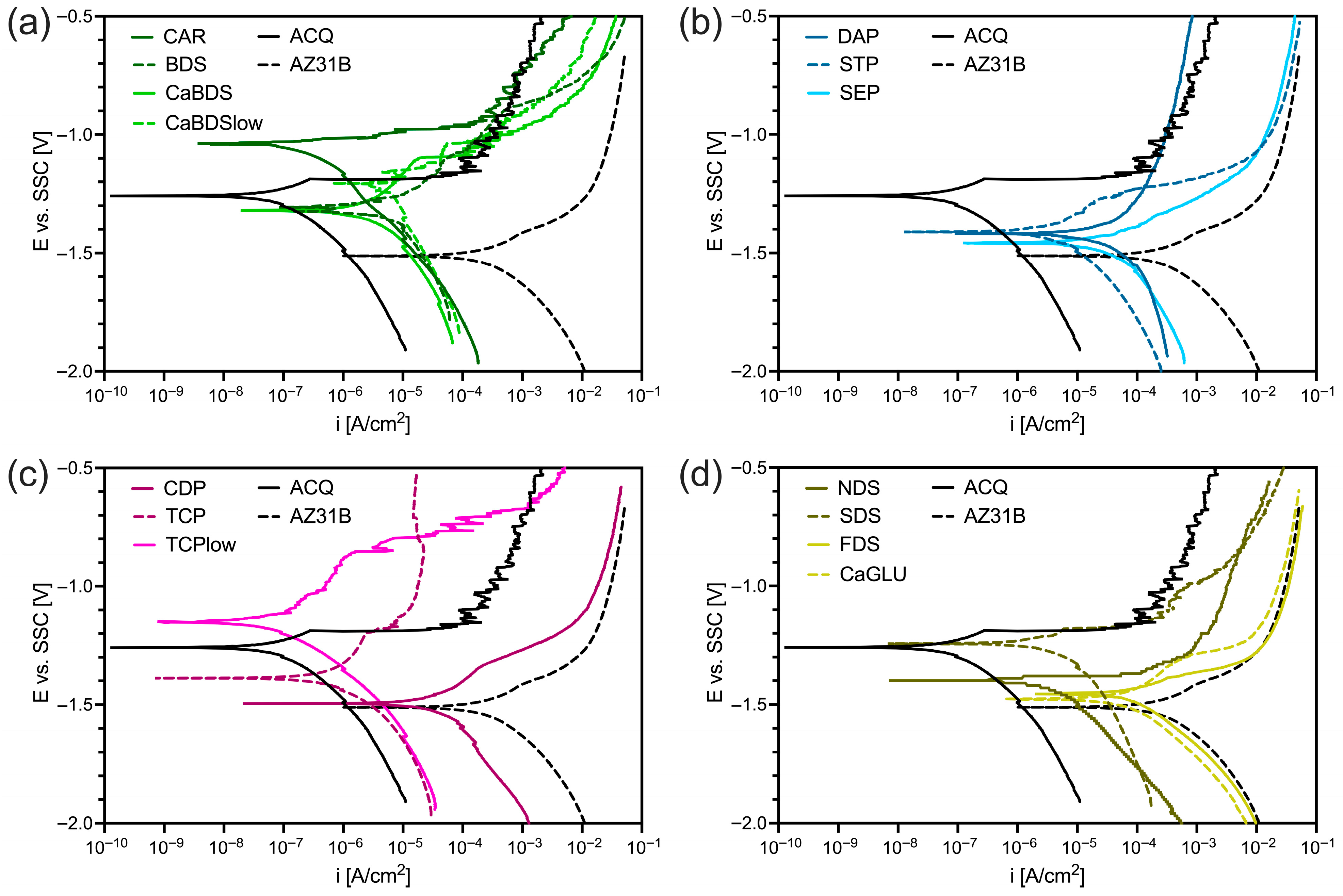
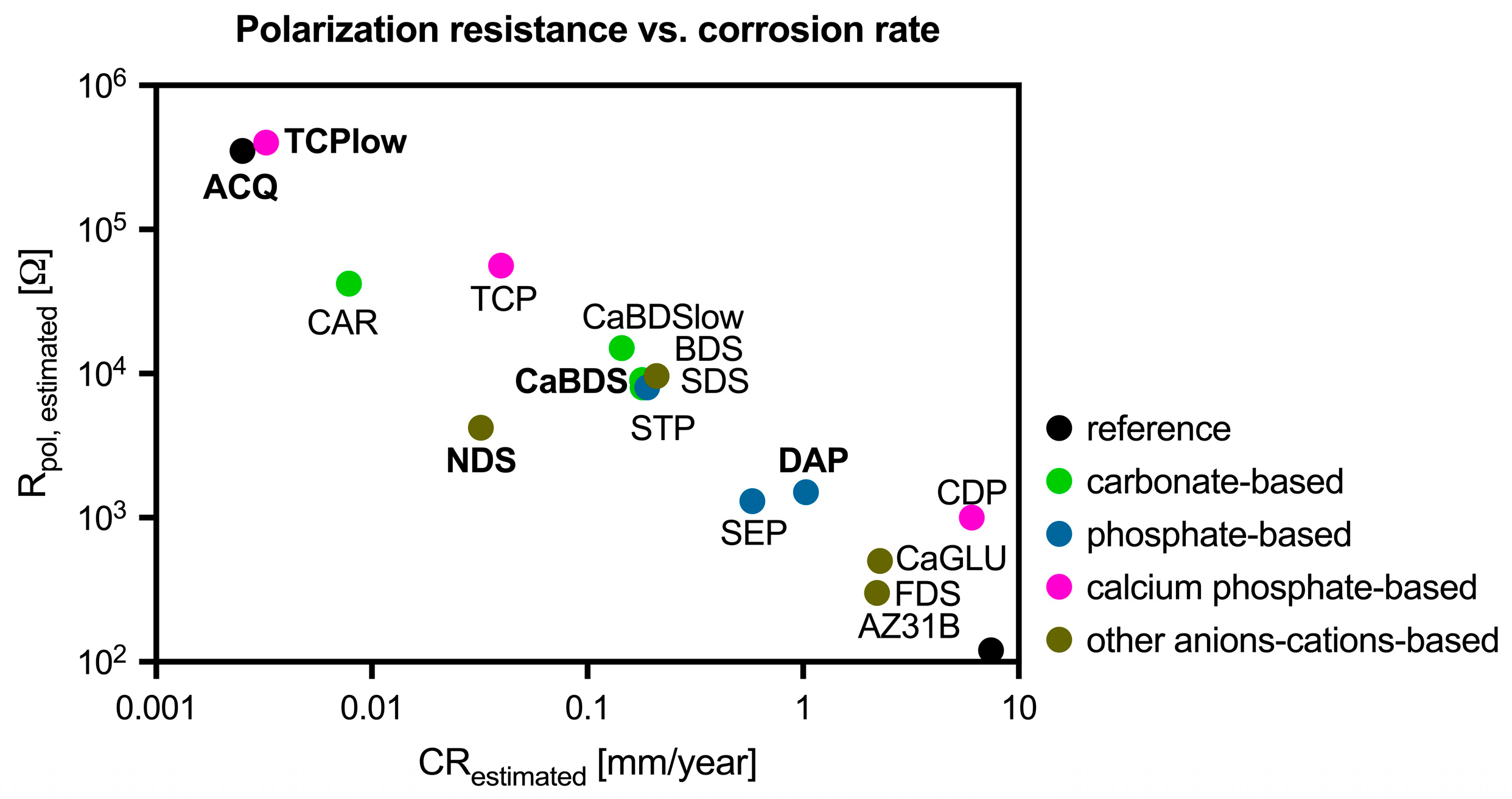
The potentiodynamic polarization tests performed in SBF provided a preliminary quantitative evaluation of corrosion resistance. The results are summarized in Figure 2 and Figure 3 (full data are reported in Table S1). The ACQ control sample demonstrated excellent corrosion resistance, with a very low corrosion current density and high estimated polarization resistance, suggesting how a simple hydrothermal treatment in water can form a highly protective layer.
Among the modified coatings, corrosion performance varied significantly. The CDP sample, despite its thickness, showed very poor corrosion resistance, with an extremely high icorr of 2.64 × 10⁻⁴ A/cm2. The DAP sample also showed poor resistance, with an icorr of 4.49 × 10⁻⁵ A/cm2. In contrast, the TCPlow sample performed exceptionally well, with estimated corrosion performances very similar to those of the ACQ control. The CaBDS sample showed a promisingly noble Ecorr (−1.12 V) and a reasonably low icorr. The NDS sample also showed a significantly nobler Ecorr compared to untreated magnesium (−1.18 V), although its icorr was higher than that of ACQ or TCPlow.
Looking at the corrosion rate–polarization resistance correlation plot (Figure 3), calcium phosphate- and carbonate-based coatings show the overall best estimated corrosion performance among coating groups, while phosphate-based systems feature an only moderately improved behavior compared to the uncoated reference. Other anion-based systems feature intermediate performance, except for the NDS sample, featuring a significantly lower estimated corrosion rate. However, all coatings (except for TCPlow) appear to fail in reaching a comparable corrosion stability to the undoped ACQ reference.
Based on a combined evaluation of coating uniformity and electrochemical behavior, five formulations were selected for the final, in-depth characterization phase:
1.
ACQ (reference).
2.
CaBDS, representing carbonate-based coatings. The CAR coating was both macroscopically and in terms of corrosion resistance (corrosion rate, polarization resistance) very similar to the ACQ sample, likely due to the low solubility of carbonate ions. Such an observation was confirmed by preliminary SEM/EDS evaluation (Figure S1) which showed no significant differences between the two.
3.
DAP, representing phosphate-based coatings (chosen despite the overall poor electrochemical results of this family of coatings, in order to investigate their long-term degradation behavior).
4.
TCPlow, representing calcium phosphate-based coatings.
5.
NDS, as a different anion-based coating.

3.2. Morphological and Physical–Chemical Characterization

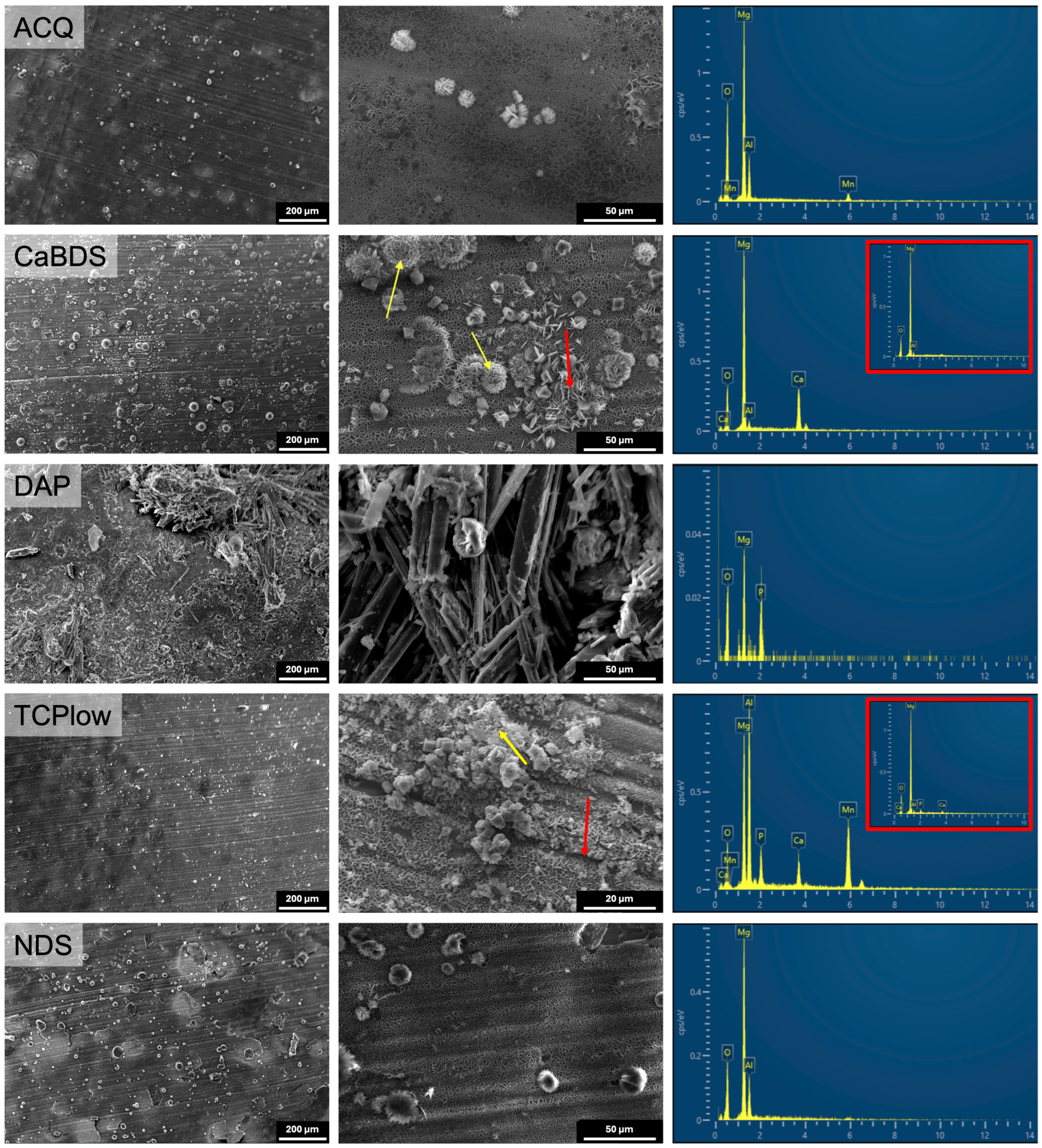
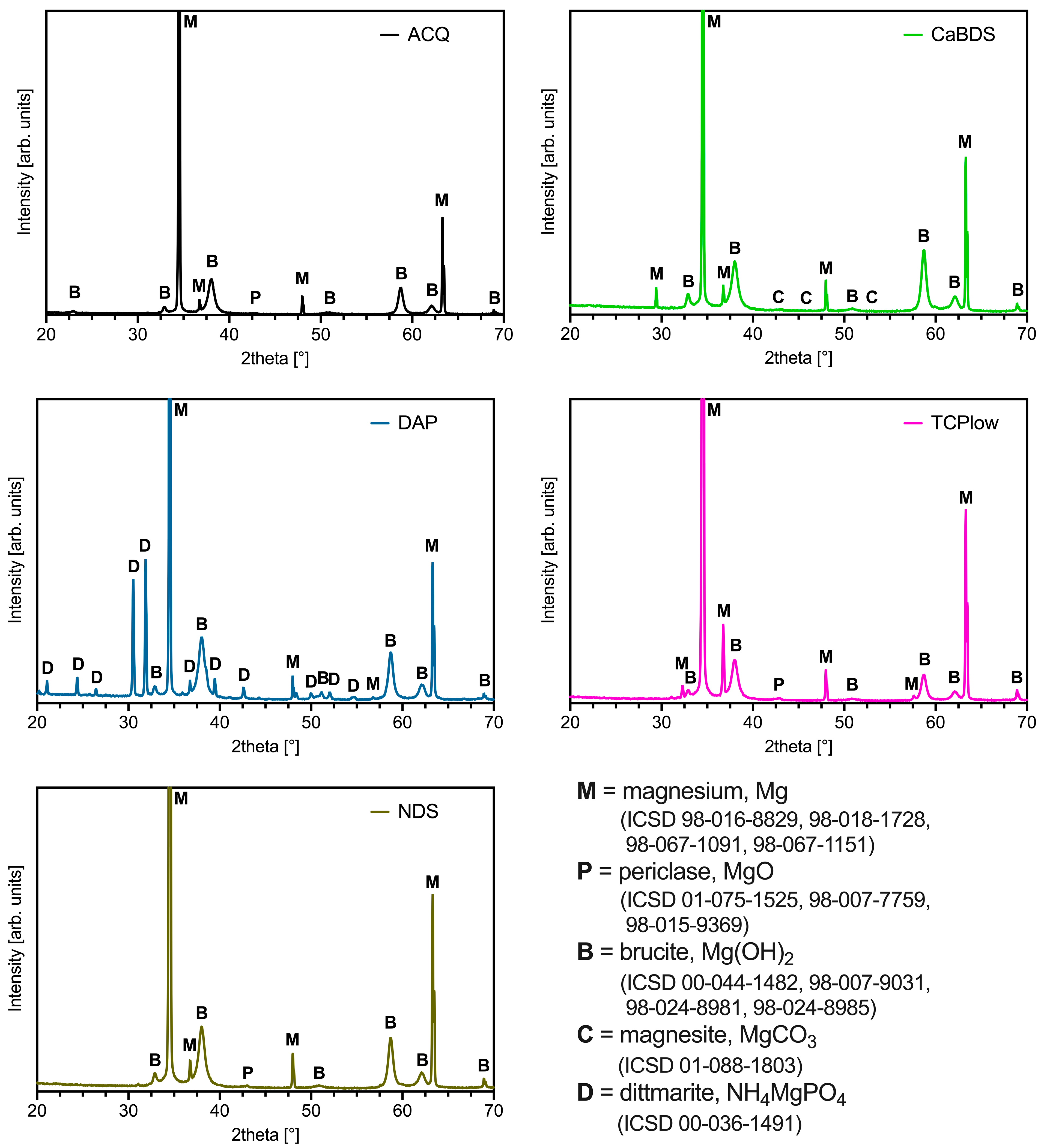
The selected coatings exhibited distinct microstructures and elemental compositions (Figure 4, cross-sectional micrographs in Figure S2), which in turn led to significantly different crystalline structures (Figure 5). Specifically, the ACQ samples showed a relatively uniform coating layer made of acicular-like crystal growths, with small, sparsely distributed accumulations. EDS confirmed the coating was almost only composed of Mg and O. The XRD analyses identified the presence of magnesium hydroxide (Mg(OH)2, brucite) in the coating, together with a non-negligible content of magnesium oxide (MgO, periclase).
The surface of CaBDS samples consisted of a homogeneous base layer decorated with numerous complex crystalline structures, identified as having both lamellar and flower-like morphologies. EDS analyses showed that the base layer (Figure 4, CaBDS, red arrow) was mainly composed of Mg and O, while the flower-like structures (yellow arrows) were rich in Ca, confirming the incorporation of calcium into these specific phases. Accordingly, XRD detected Mg, Mg(OH)2 and magnesium carbonate (MgCO3, magnesite) phases, but no crystalline MgO.
As suggested by optical images, the DAP surfaces were completely covered by a dense network of acicular (needle-like) crystals. EDS showed the presence of Mg, O, and a strong P signal across the entire surface, while the XRD spectra confirmed the coating was composed of Mg, Mg(OH)2, and a distinct phase of hydrated ammonium magnesium phosphate (NH4MgPO4, dittmarite).
The TCP coating was overall homogeneous, similar to ACQ but with more pronounced and broader outgrown agglomerates. The EDS analysis revealed that the base layer contained Mg, O, and some Ca and P, while the agglomerates were highly enriched in Ca and P (Figure 4, TCPlow, yellow arrow). However, like ACQ, the XRD spectrum only showed the presence of crystalline Mg, Mg(OH)2, and MgO phases.
Lastly, the NDS morphology was again very similar to that of the ACQ sample, with a uniform base layer and scattered crystalline precipitates. EDS showed only Mg and O, while the XRD pattern was also similar to ACQ and TCP, confirming the presence of Mg, Mg(OH)2, and MgO.
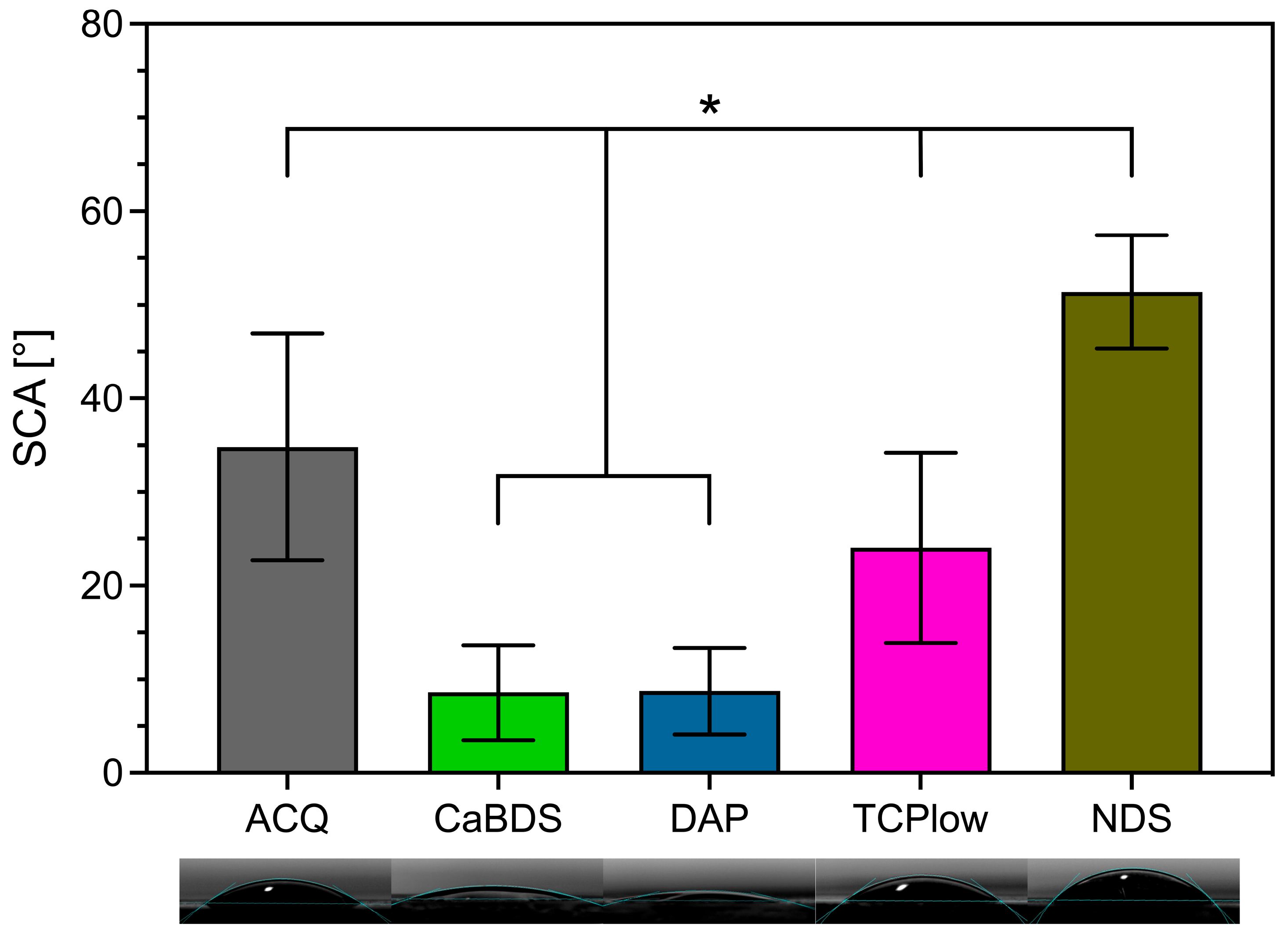
The static water contact angle measurements suggested significant differences in surface energy among coatings (Figure 6). The CaBDS and DAP coatings showed a comparable wetting behavior, both being strongly hydrophilic, with water droplets spreading out almost completely. The TCP coating was moderately hydrophilic (with a contact angle of around 25°). In contrast, the ACQ (contact angle around 35°) and, most notably, the NDS (contact angle around 51°) coatings were significantly more hydrophobic.

3.3. In Vitro Degradation

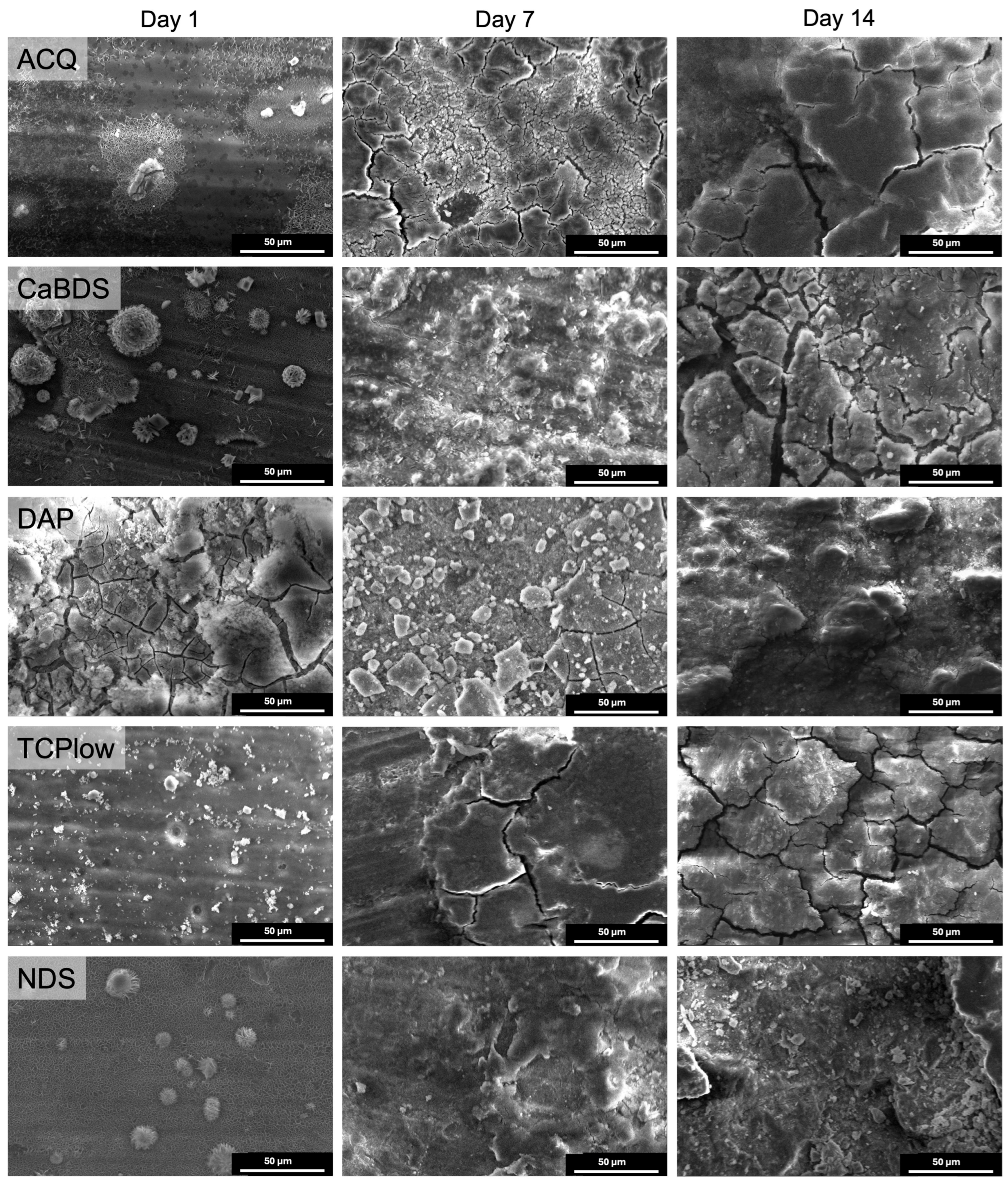
The 14-day immersion test in PBS allowed us to evaluate the dynamic evolution of the coatings under physiological-like conditions. Looking at the samples’ surface morphologies at different immersion timepoints (Figure 7, lower magnifications in Figure S3), it can be observed that at day 1 the ACQ, NDS, and CaBDS surfaces were relatively unchanged, with their pristine morphological features being still clearly visible. The DAP coating, however, showed significant alteration, with the disappearance of its fine needle-like crystals and the formation of a cracked mud-flat-like layer.
After 7 days of immersion, all coatings showed clear signs of degradation. The ACQ, CaBDS, and TCP samples developed extensive networks of cracks and were covered in a new layer of corrosion products. The DAP surface appeared to be covered in smaller, granular deposits. The NDS surface began to be covered by a new, relatively uniform corrosion product layer that started to cover the original surface features.
At day 14, degradation was advanced on all samples at a microscopic level. The ACQ, CaBDS, and TCPlow coatings were heavily cracked and delaminated in some areas. The DAP surface appeared somewhat more homogeneous but clearly degraded. The NDS surface, on the other hand, although being almost entirely covered by the new corrosion product layer, appeared relatively intact compared to the cracked layers featured by the other sample groups.
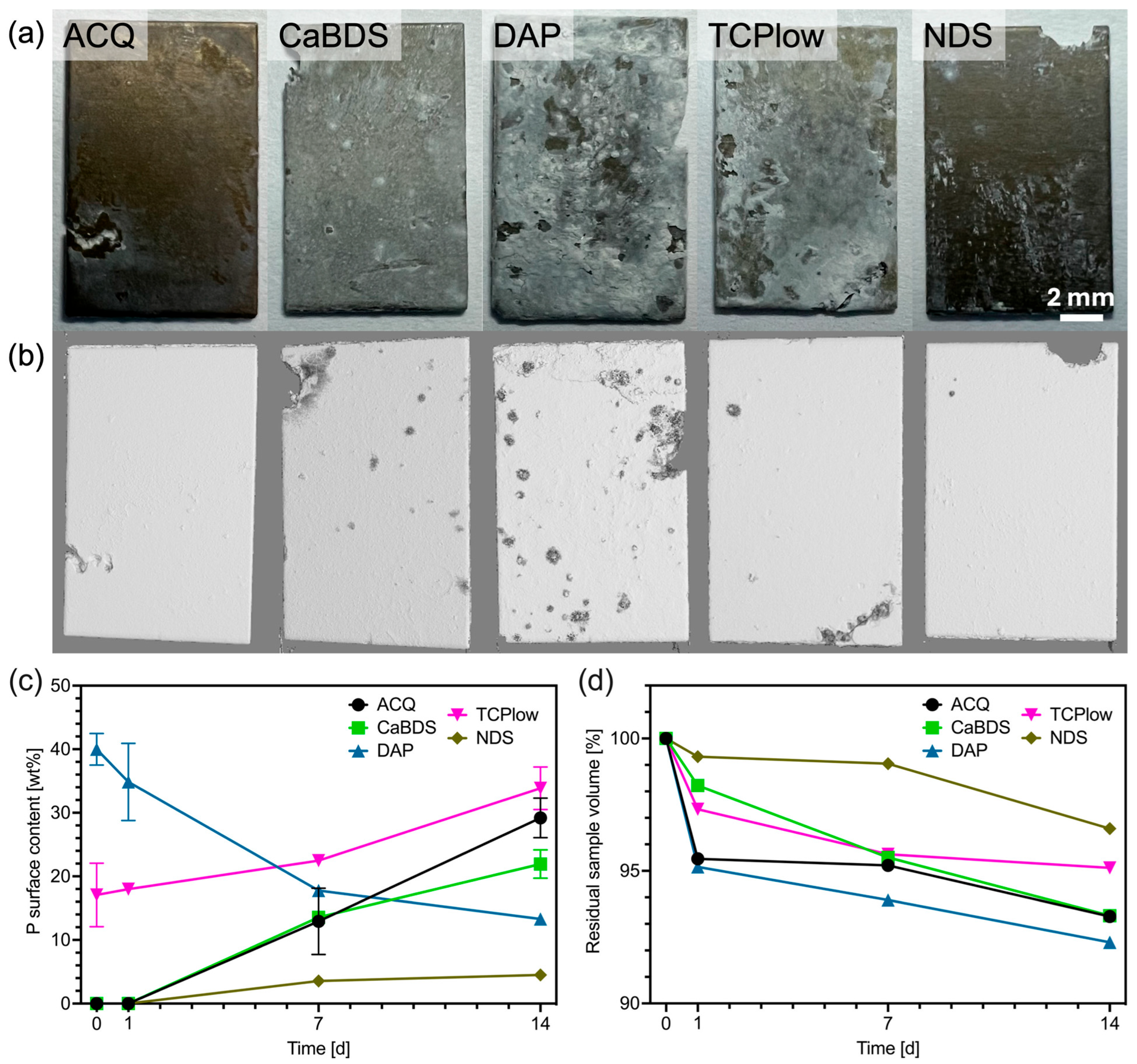
The EDS analyses performed at subsequent immersion timepoints showed a significant increase in the surface concentration of phosphorus for the ACQ, CaBDS, TCP, and NDS samples over time (Figure 8c). This indicates the formation of a phosphate-containing corrosion layer (likely including amorphous calcium or magnesium phosphate) onto the corroding surfaces, as a result of degradation in a phosphate-rich physiological-like environment. Notably, the DAP sample showed a unique trend: its initially high surface P concentration decreased over the 14 days, suggesting that its native phosphate layer was dissolving faster than the new phosphate-containing corrosion layer could precipitate from the PBS, thus indicating an overall faster degradation rate compared to the other coated surfaces.
Quantitative evaluation of volumetric losses, conducted through micro-computed tomography, was employed as the principal metric to assess long-term corrosion protection provided by the hydrothermal coatings (Figure 8). The temporal progression of corrosion, expressed as the percentage change in volume over the 14-day immersion period, is illustrated in Figure 8d.
Qualitatively, the µ-CT reconstructions (Figure 8b) revealed pronounced pitting corrosion exclusively in the DAP and CaBDS samples. In contrast, the ACQ, TCPlow, and NDS samples exhibited only localized corrosion, predominantly at the edges of the specimens. Notably, in the ACQ and TCPlow samples, the corrosion phenomena observed at these sites also propagated towards the interior of the specimen.
The quantitative volume loss data highlighted significant differences in the degradation performance of the coatings. The DAP sample performed the worst, with a rapid volume loss of over 4% after the first day of immersion and a total loss of nearly 8% after 14 days. The ACQ, CaBDS, and TCP samples all showed lower but still significant degradation, with total volume losses in the range of 6–7% at the longest timepoint.
Conversely, the NDS sample demonstrated superior performance. It exhibited minimal volume loss after 1 and 7 days, with its degradation rate only increasing in the final week. Its total volume loss after 14 days was approximately 3.5%, less than half that of the DAP sample, and significantly lower than all the other coating groups.
The analysis of the extrapolated corrosion rates at the different degradation timepoints (Table 3) further supports these observations. A progressive reduction in corrosion rate is evident for all sample groups upon immersion, in line with literature reports [31,32,33], and can be attributed to the gradual formation and stabilization of a surface corrosion product layer. This layer likely inhibits the rapid initial corrosion and eventually leads to the long-term degradation regime. Within this framework, the NDS sample again exhibited the most favorable behavior, followed by TCP and ACQ. In contrast, both DAP and CaBDS, while still showing a marked reduction in corrosion rate over time, maintained significantly higher values even after 14 days of immersion. This trend may suggest a more dynamic and less stable evolution of the corrosion layer in these samples, in accordance with the pitting corrosion phenomena observed by µ-CT scans.

4. Discussion

This study provides a comprehensive evaluation of how different bath compositions can influence the protective properties of one-step hydrothermal conversion coatings applied on AZ31B magnesium alloy. The results yield several key insights into the mechanisms of coating formation and degradation.

4.1. The Primacy of Coating Quality over Thickness

A fundamental observation highlighted by this study is the decoupling of coating thickness from the coatings’ protective efficacy. This is a critical point in the design of corrosion-resistant coatings. The CDP sample, for instance, produced the thickest coating (nearly 50 µm) but exhibited the worst corrosion performance in electrochemical tests, indicating a highly discontinuous and non-protective structure (as confirmed by the cross-sectional SEM images, Figure S2). Conversely, the high-performing NDS and ACQ coatings were among the thinner ones (about 17 and 15 µm thick, respectively). This confirms that a thick coating is not necessarily beneficial in terms of corrosion protection if it is not sufficiently dense, homogeneous, and well-adhered. As supported by literature data, factors like porosity, microcracks, and chemical stability are far more critical determinants of a coating’s ability to act as a barrier than its bulk thickness [34]. A thick, defective layer can even be detrimental, creating crevices that trap corrosive ions and accelerate localized corrosion, thus providing a corrosion behavior only marginally better or even worse than that of the uncoated substrate.
In general, for a given compound, coatings obtained from low-concentration solutions exhibited superior performances in terms of polarization resistance and corrosion rate. This improvement is primarily attributed to the reduced number and smaller size of surface accumulations observed in these coatings. Such accumulations can compromise the homogeneity of the coating and promote the formation of localized anode-cathode pairs on the sample surface during degradation, thereby accelerating electrochemical corrosion processes [33].

4.2. The Critical Role of Magnesium Oxide

The XRD analyses revealed a strong correlation between the presence of a crystalline magnesium oxide (MgO, periclase) phase and improved corrosion performance. The best performing coatings in terms of degradation stability and electrochemical corrosion rates (NDS, ACQ, and TCP) all contained detectable MgO in addition to the expected Mg(OH)2. In contrast, the less protective CaBDS and DAP coatings were primarily composed of Mg(OH)2 and other less chemically stable compounds. This strongly suggests that the formation of MgO is a key factor in creating a more robust protective layer.
This finding is well-supported by fundamental chemistry. While Mg(OH)2 is the primary product of Mg corrosion in water, it has a Pilling-Bedworth ratio of ~1.77, which can induce compressive stresses and cracking in the layer. More importantly, it is also relatively soluble in chloride rich environments, such as physiological fluids [35]. MgO, on the other hand, is more thermodynamically stable and significantly less soluble than Mg(OH)2 in aqueous environments [36]. Therefore, a composite layer containing a stable MgO phase provides a more effective and durable barrier against the penetration of corrosion promoting Cl ions. The hydrothermal conditions applied in this work (160 °C) appear to be sufficient to promote the dehydration of some of the initially formed Mg(OH)2 into the more stable MgO, and the solution chemistry (e.g., the presence of nitrate ions in NDS) may further catalyze or favor such conversion [37].

4.3. Performance Analysis of the Individual Coating Systems

  • ACQ (deionized water): The simple treatment in water produced a markedly effective coating. Its good performance (icorr of 0.11 μA/cm2, SCA of about 35°, in vitro corrosion rate of 0.39 mm/year) can be ascribed to the formation of a stable MgO phase and to its overall uniform and almost defectless structure, although its inherently simple chemical structure limited its overall performance compared to other tested sample groups.
  • CaBDS (sodium bicarbonate and calcium nitrate): This coating successfully incorporated calcium into its flower-like carbonate structures, offering potential bioactivity. However, its corrosion resistance was significantly inferior compared to the top performers (icorr of 7.82 μA/cm2). The absence of an MgO phase and its highly hydrophilic nature (SCA of about 9°) likely contributed to its faster degradation. The complex, high-surface-area morphology of the flower-like crystals may have also provided a greater number of sites for localized corrosion to occur.
  • DAP (diammonium hydrogen phosphate): This coating performed poorly across all metrics (icorr of 44.9 μA/cm2, in vitro corrosion rate of 0.49 mm/year) despite its high thickness (about 35 μm) and crystalline nature. The dittmarite phase formed revealed to be not stable in the PBS solution, as shown by the rapid initial volume loss (with a 5% volume reduction after only one day of immersion) and the decrease in surface phosphorus concentration over time (from 40wt% to 13wt%). Its highly hydrophilic character (SCA of about 9°) and acicular morphology, prone to cracking, likely created a porous structure that offered limited barrier against penetration of the degradation medium.
  • TCP (tricalcium phosphate): This coating showed excellent initial electrochemical resistance, nearly matching the ACQ control (icorr of 0.14 μA/cm2 vs. 0.11 μA/cm2). It successfully incorporated Ca and P and formed a protective MgO-containing layer. However, its long-term degradation was slightly more pronounced than that of NDS (with an estimated CR of 0.30 mm/year vs. 0.20 mm/year). The presence of distinct Ca-P agglomerates again led to compositional heterogeneities that acted as initiation sites for localized corrosion over time [38].
  • NDS (sodium nitrate): This coating showed the best overall performance in long-term degradation tests (volume loss of about 3.5% and estimated CR of 0.20 mm/year after 14 days of immersion). Its optimal behavior can be attributed to a combination of factors: the formation of a stable MgO-containing layer, a relatively hydrophobic surface (confirmed by the highest SCA among groups, of about 51°), and a uniform morphology. While its initial electrochemical corrosion current was not the lowest (1.42 μA/cm2), its ability to form a stable, slowly degrading passive corrosion layer in PBS proved to be the most important characteristic for long-term protection.
Overall, although coatings produced in phosphate- and carbonate-based environments show interesting results, a consistently better corrosion behavior was proven by hydrothermal coatings produced using the milder solutions containing either sodium nitrate or only deionised water, without any solute addition. Notably, the ACQ sample group serves as an important baseline, demonstrating that an increase in complexity of the bath formulations does not necessarily drive significant improvements in corrosion resistance.

4.4. Degradation Mechanism and Implications

The immersion tests revealed a common degradation mechanism for all the coating groups. After an initial setting period, the coatings began to crack and delaminate, allowing the PBS solution to reach the underlying AZ31 substrate. Concurrently, a new layer, rich in phosphorus and calcium deposited either from the degradation medium or from the partial coating dissolution, precipitates onto the surface. This dynamic process of native coating dissolution and new mineral precipitation is characteristic of Mg degradation in phosphate-buffered solutions [34]. The superior performance of the NDS coating suggests that its initial layer was more effective at slowing down this entire cascade, delaying the onset of severe cracking and substrate exposure. The ability to promote the formation of a stable, apatite-like layer in situ is desirable for bioactivity, but it must be balanced with the control of the underlying substrate corrosion. The NDS coating appears to achieve the best balance among the tested groups, providing stability while still allowing for eventual surface conversion in the simulated physiological fluid.

4.5. µ-CT Scanning as a Promising Alternative for Corrosion Assessment

In the context of evaluating the corrosion behavior of surface modified magnesium alloys for bioresorbable implant applications, micro-computed tomography (µ-CT) emerges as a highly promising analytical technique. Conventional standardized methods for corrosion assessment, such as those outlined in ISO 8407 and ASTM G1, typically rely on mass loss measurements following chemical cleaning protocols, often involving chromic acid-based solutions to remove corrosion products. However, these procedures present significant limitations when applied to surface-modified materials, particularly in the case of conversion coatings. The aggressive chemical cleaning steps indeed remove not only the deposited corrosion products layer, but also the non-degraded coating (having a similar chemical structure to such corrosion products), thus leading to inaccurate quantification of material loss and corrosion rates. In contrast, µ-CT offers a non-destructive, three-dimensional approach capable of accurately tracking the degradation process without the need for post-corrosion chemical treatments. This is particularly advantageous in the case of magnesium degradation evaluation, where preserving the integrity of the surface features is crucial for reliable analysis.
In the present study, µ-CT analyses were performed to quantitatively evaluate the degradation of coated samples, exploiting their versatility to overcome most of the specific limitations of conventional techniques. The technique provided the most conclusive evidence of the long-term corrosion behavior among investigated coatings. By enabling non-destructive direct volumetric measurements over time, this technique allowed for precise monitoring of degradation progression under physiologically relevant conditions, as well as for progressive direct corrosion rate estimation, offering a comprehensive understanding of the protective behavior imparted by different hydrothermal bath chemistries. These findings underline the value of μ-CT as a valid alternative for corrosion assessment in cases where standard mass loss protocols are inadequate or potentially misleading, particularly in the evaluation of bioresorbable systems where the surface treatment plays a crucial role in modulating degradation kinetics.

5. Conclusions

This comprehensive investigation of one-step hydrothermal treatments for AZ31B magnesium alloy performed in this work provided critical insights and a rational basis for the development and optimization of critically designed hydrothermal treatments to be applied on next-generation bioresorbable implants. This study validates the one-step hydrothermal method as a simple, scalable, and powerful tool for creating multifunctional surfaces on magnesium alloys. Through the systematic screening of twenty different solution chemistries and in-depth analysis of the most promising candidates, this study aimed at drawing some general concepts to drive the future design of hydrothermal surface modification treatments.
  • Coating quality, not thickness, dictates performance. This study shows that the protective efficacy of a hydrothermal coating is governed by its homogeneity, density, and chemical stability, rather than by its bulk thickness. Notably, the NDS coating, regardless being one of the thinnest investigated (about 17 µm, compared to thicknesses up to about 50 µm in other sample groups), exhibited the overall lowest long-term corrosion rate (0.20 mm/year) after in vitro testing.
  • The presence of MgO is critical for stability. A correlation was found between enhanced corrosion resistance and the presence of a crystalline magnesium oxide (MgO) phase within the coating. The most stable coatings (NDS, ACQ, TCP) contained both MgO and Mg(OH)2 phases, suggesting that the presence of MgO, even if not predominant, provides a more robust barrier to corrosion than Mg(OH)2 alone.
  • A trade-off exists between bioactivity and corrosion resistance. While coatings containing calcium and phosphate (CaBDS, TCP) successfully incorporated bioactive elements, they exhibited slightly compromised corrosion performance (with in vitro corrosion rates of 0.43 and 0.30 mm/year, respectively), highlighting the need to carefully balance these competing properties in coating design.
Among all the evaluated baths, a simple sodium nitrate solution appeared to be the most effective formulation, producing coatings with superior long-term degradation resistance, exhibiting the lowest volumetric loss (about 3%) after 14 days. Moreover, the µ-CT technique stands out as a promising candidate analysis to effectively and reliably evaluate the degradation behavior of materials and coatings unsuitable for other standardized corrosion testing methods.

Supplementary Materials

The following supporting information can be downloaded at: https://www.mdpi.com/article/10.3390/met15091056/s1, Figure S1: Morphological comparison between ACQ and CAR samples; Figure S2: High magnification (3000×) cross-sectional SEM micrographs of the selected hydrothermal coated samples; Figure S3: Representative low magnification (500×) SEM micrographs of the selected hydrothermal coated samples’ surfaces after 1 (left), 7 (center) and 14 (right) days of immersion in PBS; Table S1: Main electrochemical parameters of the coatings obtained with the screened solutions. * = software estimation based on Tafel curve fitting.

Author Contributions

Conceptualization, M.P. and R.C.; methodology, M.P., M.M. and R.C.; software, M.P. and N.M.; formal analysis, M.P. and N.M.; investigation, M.P. and N.M.; data curation, M.P. and N.M.; writing—original draft preparation, M.P.; writing—review and editing, M.P., M.M. and R.C.; visualization, M.P.; supervision, R.C. All authors have read and agreed to the published version of the manuscript.

Funding

This research received no external funding.

Data Availability Statement

The original contributions presented in this study are included in the article/Supplementary Material. Further inquiries can be directed to the corresponding author.

Acknowledgments

The authors would like to thank Hans Deyhle and Bert Müller for their support with the SEM, µCT and volumetric loss analyses performed at the University of Basel. During the preparation of this manuscript, the author(s) used ChatGPT 4 and DeepL Translator for superficial text editing. The authors have reviewed and edited the output and take full responsibility for the content of this publication.

Conflicts of Interest

The authors declare no conflicts of interest.

Abbreviations

The following abbreviations are used in this manuscript:
SEMScanning Electron Microscopy
PBSDulbecco’s Phosphate-Buffered Saline Solution
SBFSimulated Body Fluid
SCAStatic Contact Angle
µ-CTMicro-Computed Tomography

References

  1. Geetha, M.; Singh, A.K.; Asokamani, R.; Gogia, A.K. Ti Based Biomaterials, the Ultimate Choice for Orthopaedic Implants—A Review. Prog. Mater. Sci. 2009, 54, 397–425. [Google Scholar] [CrossRef]
  2. Marin, E.; Lanzutti, A. Biomedical Applications of Titanium Alloys: A Comprehensive Review. Materials 2023, 17, 114. [Google Scholar] [CrossRef]
  3. Navarro, M.; Michiardi, A.; Castaño, O.; Planell, J.A. Biomaterials in Orthopaedics. J. R. Soc. Interface 2008, 5, 1137–1158. [Google Scholar] [CrossRef]
  4. Böstman, O.; Pihlajamäki, H. Clinical Biocompatibility of Biodegradable Orthopaedic Implants for Internal Fixation: A Review. Biomaterials 2000, 21, 2615–2621. [Google Scholar] [CrossRef]
  5. Busam, M.L.; Esther, R.J.; Obremskey, W.T. Hardware Removal: Indications and Expectations. J. Am. Acad. Orthop. Surg. 2006, 14, 113–120. [Google Scholar] [CrossRef]
  6. Vos, D.; Hanson, B.; Verhofstad, M. Implant Removal of Osteosynthesis: The Dutch Practice. Results of a Survey. J. Trauma. Manag. Outcomes 2012, 6, 6. [Google Scholar] [CrossRef]
  7. Zheng, Y.F.; Gu, X.N.; Witte, F. Biodegradable Metals. Mater. Sci. Eng. R Rep. 2014, 77, 1–34. [Google Scholar] [CrossRef]
  8. de Baaij, J.H.F.; Hoenderop, J.G.J.; Bindels, R.J.M. Magnesium in Man: Implications for Health and Disease. Physiol. Rev. 2015, 95, 1–46. [Google Scholar] [CrossRef]
  9. Li, X.; Liu, X.; Wu, S.; Yeung, K.W.K.; Zheng, Y.; Chu, P.K. Design of Magnesium Alloys with Controllable Degradation for Biomedical Implants: From Bulk to Surface. Acta Biomater. 2016, 45, 2–30. [Google Scholar] [CrossRef]
  10. Staiger, M.P.; Pietak, A.M.; Huadmai, J.; Dias, G. Magnesium and Its Alloys as Orthopedic Biomaterials: A Review. Biomaterials 2006, 27, 1728–1734. [Google Scholar] [CrossRef] [PubMed]
  11. Xie, J.; Zhang, T.; Jiang, J.; Xue, W.; Wang, W.; Ni, J.; Zhang, X.; Liu, X. Advances in Magnesium-Based Implants for Biomedical Applications: A Comprehensive Review and Future Perspectives. J. Magnes. Alloys 2025, 13, 2978–3003. [Google Scholar] [CrossRef]
  12. Nasr Azadani, M.; Zahedi, A.; Bowoto, O.K.; Oladapo, B.I. A Review of Current Challenges and Prospects of Magnesium and Its Alloy for Bone Implant Applications. Prog. Biomater. 2022, 11, 1–26. [Google Scholar] [CrossRef]
  13. Esmaily, M.; Svensson, J.E.; Fajardo, S.; Birbilis, N.; Frankel, G.S.; Virtanen, S.; Arrabal, R.; Thomas, S.; Johansson, L.G. Fundamentals and Advances in Magnesium Alloy Corrosion. Prog. Mater. Sci. 2017, 89, 92–193. [Google Scholar] [CrossRef]
  14. Gonzalez, J.; Hou, R.Q.; Nidadavolu, E.P.S.; Willumeit-Römer, R.; Feyerabend, F. Magnesium Degradation under Physiological Conditions—Best Practice. Bioact. Mater. 2018, 3, 174–185. [Google Scholar] [CrossRef]
  15. Witte, F.; Fischer, J.; Nellesen, J.; Crostack, H.-A.; Kaese, V.; Pisch, A.; Beckmann, F.; Windhagen, H. In Vitro and in Vivo Corrosion Measurements of Magnesium Alloys. Biomaterials 2006, 27, 1013–1018. [Google Scholar] [CrossRef]
  16. Agarwal, S.; Curtin, J.; Duffy, B.; Jaiswal, S. Biodegradable Magnesium Alloys for Orthopaedic Applications: A Review on Corrosion, Biocompatibility and Surface Modifications. Mater. Sci. Eng. C 2016, 68, 948–963. [Google Scholar] [CrossRef]
  17. Xia, S.; Wang, L.; Wang, Q.; Long, J.; Zhang, Z.; Chai, Y.; Xia, D.; Jiang, B. High-Speed-Extruded BA53 Mg Alloy with Ca-Doping: Multifunctional Gains in Strength, Corrosion Resistance and Thermal Stability. J. Alloys Compd. 2025, 1039, 182999. [Google Scholar] [CrossRef]
  18. Wang, L.; Xia, S.; Wang, Q.; Qin, X.; Jiang, B. Simultaneously Enhancing the Mechanical Properties and Corrosion Resistance in a Selective Laser Melting AZ91 Magnesium Alloy by Hot Rolling and Subsequent Annealing. J. Mater. Res. Technol. 2025, 36, 8503–8516. [Google Scholar] [CrossRef]
  19. Johari, N.A.; Alias, J.; Zanurin, A.; Mohamed, N.S.; Alang, N.A.; Zain, M.Z.M. Anti-Corrosive Coatings of Magnesium: A Review. Mater. Today Proc. 2022, 48, 1842–1848. [Google Scholar] [CrossRef]
  20. Wu, T.; Zhang, K. Corrosion and Protection of Magnesium Alloys: Recent Advances and Future Perspectives. Coatings 2023, 13, 1533. [Google Scholar] [CrossRef]
  21. Yin, Z.-Z.; Qi, W.-C.; Zeng, R.-C.; Chen, X.-B.; Gu, C.-D.; Guan, S.-K.; Zheng, Y.-F. Advances in Coatings on Biodegradable Magnesium Alloys. J. Magnes. Alloys 2020, 8, 42–65. [Google Scholar] [CrossRef]
  22. Miklaszewski, A.; Kowalski, K.; Jurczyk, M. Hydrothermal Surface Treatment of Biodegradable Mg-Materials. Metals 2018, 8, 894. [Google Scholar] [CrossRef]
  23. Zhu, Y.; Wu, G.; Zhang, Y.-H.; Zhao, Q. Growth and Characterization of Mg(OH)2 Film on Magnesium Alloy AZ31. Appl. Surf. Sci. 2011, 257, 6129–6137. [Google Scholar] [CrossRef]
  24. Yoshimura, M.; Byrappa, K. Hydrothermal Processing of Materials: Past, Present and Future. J. Mater. Sci. 2008, 43, 2085–2103. [Google Scholar] [CrossRef]
  25. Zhu, Y.; Zhao, Q.; Zhang, Y.-H.; Wu, G. Hydrothermal Synthesis of Protective Coating on Magnesium Alloy Using De-Ionized Water. Surf. Coat. Technol. 2012, 206, 2961–2966. [Google Scholar] [CrossRef]
  26. Hornberger, H.; Virtanen, S.; Boccaccini, A.R. Biomedical Coatings on Magnesium Alloys—A Review. Acta Biomater. 2012, 8, 2442–2455. [Google Scholar] [CrossRef]
  27. Kim, S.-Y.; Kim, Y.-K.; Ryu, M.-H.; Bae, T.-S.; Lee, M.-H. Corrosion Resistance and Bioactivity Enhancement of MAO Coated Mg Alloy Depending on the Time of Hydrothermal Treatment in Ca-EDTA Solution. Sci. Rep. 2017, 7, 9061. [Google Scholar] [CrossRef] [PubMed]
  28. Ali, A.; Iqbal, F.; Ahmad, A.; Ikram, F.; Nawaz, A.; Chaudhry, A.A.; Siddiqi, S.A.; Rehman, I. Hydrothermal Deposition of High Strength Calcium Phosphate Coatings on Magnesium Alloy for Biomedical Applications. Surf. Coat. Technol. 2019, 357, 716–727. [Google Scholar] [CrossRef]
  29. Jiang, P.; Hou, R.; Zhu, S.; Guan, S. A Robust Calcium Carbonate (CaCO3) Coating on Biomedical MgZnCa Alloy for Promising Corrosion Protection. Corros. Sci. 2022, 198, 110124. [Google Scholar] [CrossRef]
  30. Kokubo, T.; Takadama, H. How Useful Is SBF in Predicting in Vivo Bone Bioactivity? Biomaterials 2006, 27, 2907–2915. [Google Scholar] [CrossRef]
  31. Liu, L.; Gebresellasie, K.; Collins, B.; Zhang, H.; Xu, Z.; Sankar, J.; Lee, Y.-C.; Yun, Y. Degradation Rates of Pure Zinc, Magnesium, and Magnesium Alloys Measured by Volume Loss, Mass Loss, and Hydrogen Evolution. Appl. Sci. 2018, 8, 1459. [Google Scholar] [CrossRef]
  32. Song, G.-L.; Atrens, A. Recently Deepened Insights Regarding Mg Corrosion and Advanced Engineering Applications of Mg Alloys. J. Magnes. Alloys 2023, 11, 3948–3991. [Google Scholar] [CrossRef]
  33. Wei, L.; Gao, Z. Recent Research Advances on Corrosion Mechanism and Protection, and Novel Coating Materials of Magnesium Alloys: A Review. RSC Adv. 2023, 13, 8427–8463. [Google Scholar] [CrossRef]
  34. Wu, G.; Ibrahim, J.M.; Chu, P.K. Surface Design of Biodegradable Magnesium Alloys—A Review. Surf. Coat. Technol. 2013, 233, 2–12. [Google Scholar] [CrossRef]
  35. Ghali, E. Activity and Passivity of Magnesium (Mg) and Its Alloys. In Corrosion of Magnesium Alloys; Elsevier: Amsterdam, The Netherlands, 2011; pp. 66–114. [Google Scholar]
  36. Nahdi, K.; Rouquerol, F.; Trabelsi Ayadi, M. Mg(OH)2 Dehydroxylation: A Kinetic Study by Controlled Rate Thermal Analysis (CRTA). Solid State Sci. 2009, 11, 1028–1034. [Google Scholar] [CrossRef]
  37. Shkatulov, A.; Krieger, T.; Zaikovskii, V.; Chesalov, Y.; Aristov, Y. Doping Magnesium Hydroxide with Sodium Nitrate: A New Approach to Tune the Dehydration Reactivity of Heat-Storage Materials. ACS Appl. Mater. Interfaces 2014, 6, 19966–19977. [Google Scholar] [CrossRef]
  38. Lin, Y.; Cai, S.; Jiang, S.; Xie, D.; Ling, R.; Sun, J.; Wei, J.; Shen, K.; Xu, G. Enhanced Corrosion Resistance and Bonding Strength of Mg Substituted β-Tricalcium Phosphate/Mg(OH)2 Composite Coating on Magnesium Alloys via One-Step Hydrothermal Method. J. Mech. Behav. Biomed. Mater. 2019, 90, 547–555. [Google Scholar] [CrossRef]
Figure 1. Representative macroscopic images of the samples obtained with all the screened hydrothermal baths.
Metals 15 01056 g001
Figure 2. Representative Tafel plots of the samples obtained with the screened hydrothermal baths featuring a stable coating, compared to both the reference (ACQ) coating and untreated AZ31B. (a) carbonate-based systems; (b) phosphate-based systems; (c) calcium phosphate-based systems; (d) other anion–cation-based systems.
Metals 15 01056 g002
Figure 3. Estimated polarization resistance-corrosion rate correlation plot of the samples obtained with the screened hydrothermal baths featuring a stable coating. Colors indicate the different hydrothermal bath groups. Samples with bold names were selected for further characterization.
Metals 15 01056 g003
Figure 4. Low (left) and high (middle) magnification SEM images of the selected hydrothermal coated surfaces, with corresponding representative EDS spectra. Red lined spectra correspond to the regions indicated by red arrows. Yellow arrows indicate the flower-like crystal structures.
Metals 15 01056 g004
Figure 5. X-ray diffractograms of the selected hydrothermal coated surfaces. Letters indicate the detected phases.
Metals 15 01056 g005
Figure 6. Static contact angle data of the selected hydrothermal coated surfaces with representative images. * = p < 0.05.
Metals 15 01056 g006
Figure 7. Representative high magnification (2500×) SEM micrographs of the selected hydrothermal coated samples’ surfaces after 1 (left), 7 (center) and 14 (right) days of immersion in PBS.
Metals 15 01056 g007
Figure 8. (a) Representative macroscopic images of the selected samples after 14 days of immersion in PBS. (b) Sample reconstructions obtained via µ-CT scans. (c) Evolution of phosphate levels at the samples’ surfaces during immersion testing. (d) Residual volumes of the selected hydrothermally coated samples, quantified over µ-CT scans at different immersion times in PBS.
Metals 15 01056 g008
Table 1. Composition and molar concentration of solutes in the aqueous baths used for hydrothermal treatments.
GroupNameCompositionConcentration [M]
WaterACQdeionized H2O-
Carbonate-basedCARCaCO30.05
BDSNaHCO30.25
NBDSNaHCO3 + NaNO30.25 + 0.05
CaBDSNaHCO3 + Ca(NO3)2 4H2O0.25 + 0.25
Ca2BDSNaHCO3 + Ca(NO3)2 4H2O0.25 + 0.50
CaBDSlowNaHCO3 + Ca(NO3)2 4H2O0.05 + 0.05
Phosphate-basedDAPNH4H2PO40.25
STPNa5P3O100.05
SEP[Na(PO3)]60.05
Calcium phosphate-basedCaDAPNH4H2PO4 + Ca(NO3)2 4H2O0.25 + 0.50
CDPCa(H2PO4)20.05
TCPCa3(PO4)20.25
TCPlowCa3(PO4)20.05
Other anions and cationsNDSNaNO30.05
SDSNa2SiO30.05
FDSNaF0.05
CeNCe(NO3)2 6H2O0.05
CuNCu(NO3)2 3H2O0.05
CaGLU(C6H11O7)2Ca H2O0.05
Table 2. Coating thickness obtained with all the screened solutions. n.a. = coating not obtained or too brittle.
GroupNameCoating Thickness [µm]
WaterACQ15.27 ± 0.89
Carbonate-basedCAR16.84 ± 0.28
BDS37.80 ± 1.43
NBDSn.a.
CaBDS29.71 ± 5.67
Ca2BDSn.a.
CaBDSlow15.09 ± 0.35
Phosphate-basedDAP34.73 ± 0.07
STP16.64 ± 1.85
SEP10.61 ± 1.10
Calcium phosphate-basedCaDAPn.a.
CDP47.28 ± 1.85
TCP30.56 ± 0.23
TCPlow12.76 ± 4.53
Other anions and cationsNDS16.59 ± 0.89
SDS10.17 ± 0.16
FDS<1
CeNn.a.
CuNn.a.
CaGLU6.87 ± 1.05
Table 3. Corrosion rates of the selected hydrothermally coated samples calculated from volume loss data.
NameCR @ 1d [mm/year]CR @ 7d [mm/year]CR @ 14d [mm/year]
ACQ3.73 ± 0.0040.56 ± 0.0040.39 ± 0.004
CaBDS1.62 ± 0.0090.58 ± 0.0080.43 ± 0.006
DAP4.33 ± 0.0080.78 ± 0.0070.49 ± 0.006
TCPlow2.29 ± 0.0050.54 ± 0.0060.30 ± 0.004
NDS0.57 ± 0.0020.11 ± 0.0020.20 ± 0.001
Disclaimer/Publisher’s Note: The statements, opinions and data contained in all publications are solely those of the individual author(s) and contributor(s) and not of MDPI and/or the editor(s). MDPI and/or the editor(s) disclaim responsibility for any injury to people or property resulting from any ideas, methods, instructions or products referred to in the content.