Article

High-Temperature Corrosion Behavior of 12Cr18Ni10Ti Grade Austenitic Stainless Steel Under Chlorination Conditions

by
Yuliya Baklanova
,
Yerzhan Sapatayev
and
Kuanysh Samarkhanov
*
Institute of Atomic Energy, Branch National Nuclear Center of the Republic of Kazakhstan, Kurchatov 071100, Kazakhstan
*
Author to whom correspondence should be addressed.
Metals 2025, 15(9), 1052; https://doi.org/10.3390/met15091052
Submission received: 16 August 2025 / Revised: 11 September 2025 / Accepted: 17 September 2025 / Published: 20 September 2025
(This article belongs to the Section Corrosion and Protection)

Abstract

Ensuring the long-term integrity of structural materials in extreme environments is a critical challenge in the design of equipment for nuclear fuel cycle operations. In particular, the durability of materials exposed to high temperatures and chemically aggressive environments during the processing of irradiated reactor components remains a key concern. This study investigates the high-temperature corrosion behavior of 12Cr18Ni10Ti austenitic stainless steel in the reaction chamber of a beryllium chlorination plant developed for recycling irradiated beryllium reflectors from the JMTR (Japan Materials Testing Reactor). The chlorination process was conducted at temperatures ranging from 500 °C to 1000 °C in a chlorine-rich atmosphere. Post-operation analysis of steel samples extracted from the chamber revealed that uniform wall thinning was the predominant degradation mechanism. However, in high-temperature regions near the heating element, localized forms of damage, specifically pitting and intergranular corrosion, were detected, indicating that thermal stresses exacerbated localized attack. These findings contribute to the assessment of the service life of structural components under extreme conditions and offer practical guidance for material selection and design optimization in high-temperature chlorination systems used in nuclear applications.

1. Introduction

The development of effective technological solutions for handling spent structural materials from research nuclear facilities remains a critical challenge in the nuclear industry [1,2,3,4,5]. During the decontamination of beryllium reflectors irradiated in research reactors, high-temperature chlorination has emerged as a promising method for removing accumulated radionuclides [6,7,8,9,10]. This process enables the conversion of beryllium and the radionuclides it contains into volatile chlorides, followed by their separation and disposal.
However, the implementation of this process is associated with several significant challenges, including high toxicity, radiological hazards, and a lack of systematic data on the rates and mechanisms of chlorine interaction with beryllium at temperatures above 500 °C. To address this, a sealed reaction chamber was developed [9,11,12] with a rectangular welded design manufactured from 12Cr18Ni10Ti stainless steel in accordance with GOST 5632-72 tubing [13]. During operation, the chamber is exposed to an aggressive chlorine gas medium at elevated temperatures, and due to the exothermic nature of the chlorine–beryllium reaction, the internal temperature can rise to 700–1000 °C. The most thermally stressed region is the heater zone containing beryllium, while weld quality is critical for ensuring leak-tightness and overall system reliability [9,11,12].
Austenitic corrosion-resistant steel 12Cr18Ni10Ti (analogous to AISI 321) was selected as the construction material for the reaction chamber due to its high resistance to intergranular corrosion and proven performance in chemically aggressive environments at elevated temperatures. Nevertheless, its corrosion behavior in gaseous chlorine above 500 °C has not been systematically investigated. Previous findings describe the corrosion of steels and nickel-based alloys in molten lithium and beryllium fluorides at 650–700 °C under chloride environments [14,15,16,17], but a unified mechanism of high-temperature chlorine-induced degradation of steels has yet to be established. It is widely recognized that one of the key drivers of general corrosion in molten chlorides is the presence of oxidizing agents [18,19], including medium cations, impurities, and components of structural materials in contact with the melt [20,21].
Furthermore, studies have shown that beryllium actively interacts with technical-grade iron and molybdenum, producing reaction layers up to 50–100 µm thick at 800 °C after 6 h of exposure [22]. Reference data indicate that the corrosion rate of 12Cr18Ni10Ti steel in chlorine is 3.04 mm/year at 344 °C and exceeds 10 mm/year at 398 °C, making its use above 350 °C undesirable without specialized investigation [20]. Additionally, research on 321 steel (compositionally similar to 12Cr18Ni10Ti) has revealed high sensitivity to temperature, the presence of chlorides [16,23,24,25], and oxidizing agents [18,19,26,27].
Thus, there is a clear lack of systematic data on the behavior of 12Cr18Ni10Ti steel under high-temperature chlorination conditions, particularly in the presence of irradiated beryllium. At the same time, current research in this field is largely focused on detritiation (removal of tritium) from irradiated beryllium or on the development of laboratory-scale purification methods. However, no industrial-scale technology has yet been established, and irradiated beryllium is currently stored as radioactive waste. The foundation for potential industrial implementation was laid by the “dry” method developed at JAEA [28], in which beryllium and its main radionuclides are converted into chlorides, followed by the reduction of beryllium back to metallic form. This gap motivated the present study, which investigates the corrosion behavior of 12Cr18Ni10Ti steel in the reaction chamber of a beryllium chlorination facility developed for processing irradiated beryllium reflectors from the JMTR [29]. This experimental context enabled testing under conditions closely approximating real-world operation, involving both severe thermal gradients and chemically aggressive media.
Beyond the specific context of JMTR, the corrosion behavior of austenitic stainless steels such as 12Cr18Ni10Ti in chlorine-rich high-temperature environments is also relevant to the long-term structural integrity and decommissioning strategies of fast reactors. As the world’s first industrial fast neutron reactor with a sodium coolant, BN-350 [30,31,32,33] represented a foundational milestone in the BN-series, including the BN-600, BN-800, and BN-1200M designs. Although its operation officially ended in 1999 and the reactor has been decommissioned, the evaluation of long-term corrosion degradation remains crucial for ensuring safe dismantling and developing effective treatment technologies for irradiated stainless steel components [34].
This study aims to comprehensively assess the nature, depth, and mechanisms of corrosion damage in 12Cr18Ni10Ti steel exposed to chlorine conditions at temperatures up to 1000 °C. Particular emphasis is placed on thermally affected zones and welded joints, with attention to how welding defects influence localized corrosion. The findings are expected to define the limiting conditions for the reliable use of 12Cr18Ni10Ti steel and to provide guidance for the design of similar facilities.

2. Materials and Methods

The experiments were carried out at the IAE branch of the NNC RK using a high-temperature chlorination facility based on the “dry” purification method developed at JAEA [28]. This method converts beryllium and associated radionuclides into volatile chlorides, which are subsequently removed and separated.
In these experiments, a rod from the beryllium reflector of the JMTR research reactor, grade S-200F (Brush Wellman Inc., Cleveland, OH, USA), was used [35]. The irradiation period was from 1968 to 1975 under a thermal neutron flux of approximately 8.0 × 10¹³ n/cm2/s and a fast neutron flux of 7.5 × 10¹² n/cm2/s, with a total fluence of ~1020 n/cm2. The reflector rod contained 98.39 at.% beryllium, ~1.3 at.% beryllium oxide, and ~0.31 at.% of other chemical elements. The chemical composition is summarized in Table 1, while the radionuclide inventory is reported in [36]. The chemical composition of 12Cr18Ni10Ti steel, presented in Table 1, is based on the material certificate provided by the manufacturer.
The reaction chamber of the irradiated beryllium processing facility—a cyclic chlorinator—is a welded rectangular structure made from a 57 mm pipe (made of 12Cr18Ni10Ti grade stainless steel), with two flanged connections. To ensure safe operation at elevated temperatures, the reaction chamber was fabricated from 12Cr18Ni10Ti austenitic stainless steel (analogous to AISI 321) instead of quartz glass, which was used in the initial JAEA design. The chemical composition of the steel is provided in Table 2.
The schematic diagram of the chlorination facility is shown in Figure 1a. The installation consisted of a gas supply and exhaust system, a cyclic chlorinator, a cobalt chloride filter, heat exchangers, and collection tanks for beryllium chloride and hydrochloric acid. The cyclic design of the chlorinator allowed for regulation of the completeness of the chlorine–beryllium reaction over a wide range of rates by adjusting the working cycle time.
Uniform heating of the chamber was achieved by natural convection of the working gases (argon during purging, followed by chlorine during reaction) along the closed circuit of the chlorinator. This circulation was maintained by a diagonally positioned heater and cooler, which created a ~100 °C temperature difference and induced a stable average reagent flow velocity of ~0.8 m/s. The reaction chamber itself measured 1 × 2 m (with a rectangular welded design made from steel tubing (57 mm in diameter with a wall thickness of 3.85 mm) and was constructed from 12Cr18Ni10Ti austenitic stainless steel to withstand aggressive media at high temperatures.
Chlorination of irradiated beryllium was performed by introducing chlorine into the reaction chamber at a rate of ~1 g/s. The working cycle temperature (~727 °C) ensured efficient reaction between chlorine and beryllium, producing gaseous chlorides of beryllium, cobalt, and tritium. Due to the exothermic nature of the chlorine–beryllium reaction, additional self-heating occurred, and local chamber temperatures reached up to ~650 °C during the trials.
After exiting the chlorinator, the gas mixture passed through the cobalt chloride filter (CCF), where cobalt and cesium chlorides were precipitated, while beryllium chloride, tritium, and free chlorine passed through. Hydrogen was then introduced downstream of the filter, serving two functions: (i) neutralizing residual chlorine to prevent the emission of hazardous byproducts, and (ii) providing a carrier medium for radioactive tritium. The resulting beryllium chloride and hydrogen chloride were cooled and collected in the facility’s storage tanks.
To reproduce chlorination conditions for an irradiated beryllium reflector rod, two experimental trials were conducted with a total duration of ~20 min each. During the experiments, the chamber temperature increased from an initial ~200 °C (at the moment of chlorine injection) to a maximum of ~650 °C by the end of the process, due to combined external heating and the heat released by the exothermic reaction.
After chlorination, the chamber was disassembled, and four steel specimens were extracted for metallographic analysis from the locations shown in Figure 1b:
  • Sample No. 1—tube section from the cooler zone;
  • Sample No. 2—weld joint located in the cooler zone;
  • Sample No. 3—tube section from the heater zone;
  • Sample No. 4—weld joint located in the heater zone.
Sample preparation was performed using a FORCIPOL 1V grinding–polishing machine (Metkon Instruments Inc., Bursa, Turkey). Cross sections were ground with SiC abrasive papers up to 2000 grit and polished with diamond pastes down to 1 μm. After each step, the specimens were cleaned with alcohol, rinsed, and dried in warm air. The polished surfaces were etched in a boiling 10 wt.% oxalic acid solution for 20 s to reveal the microstructure and measure the average grain size.
Microstructural investigations were carried out using a JSM-6390 scanning electron microscope (Jeol Ltd., Akishima-Shi, Tokyo, Japan).
Tungsten Inert Gas (TIG) welding, using a non-consumable electrode, is regulated by several GOST standards, in particular GOST 14771-76 [37], which defines the main types, structural elements, and dimensions of welded joints performed using arc welding in protective gases, including argon. Inspection was carried out by GOST R 50.05.09-2021 [38] and GOST 18442-80 [39].

3. Results

The difference in the internal surface condition of the walls with maximum and minimum thermal stress is of particular interest (see Figure 2).
During the post-experimental studies, a metallographic analysis was performed on the most and least thermally stressed areas of the reaction chamber, specifically at the locations of the heater, the cooler, and the welded joints in the coldest and hottest zones of the chlorinator during the technological process.

3.1. Macroscopic Analysis

This subsection summarizes the results of macroscopic observations of the internal surfaces of the specimens (see Figure 3), revealing the overall pattern of corrosive interaction with chlorine.
Visual inspection of the internal surface of Sample No. 1 (Figure 3a) revealed no evidence of corrosion products. In the heat-affected zones of Samples No. 2 and No. 4, localized brownish discoloration was observed, suggesting oxidation in these areas. At distances greater than ~3 mm from the weld seam, the internal surface of Sample No. 2 remained clean and free of visible chemical attack. In contrast, Sample No. 3 (Figure 3c), taken from the heater zone, exhibited a dense black surface film. The internal surface of Sample 4 displayed black spots up to 1 mm in diameter.

3.2. Microstructural Analysis

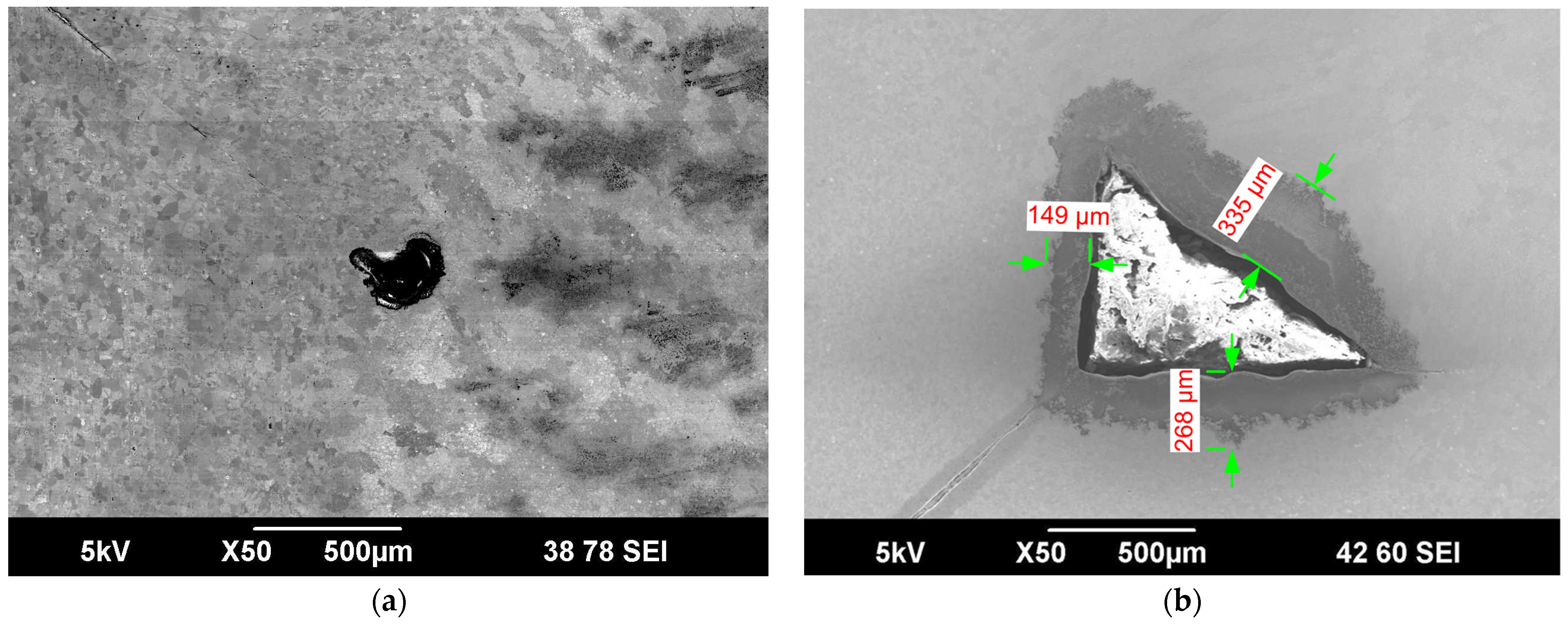
The results of microscopic investigations are presented in Figure 4, Figure 5, Figure 6 and Figure 7.
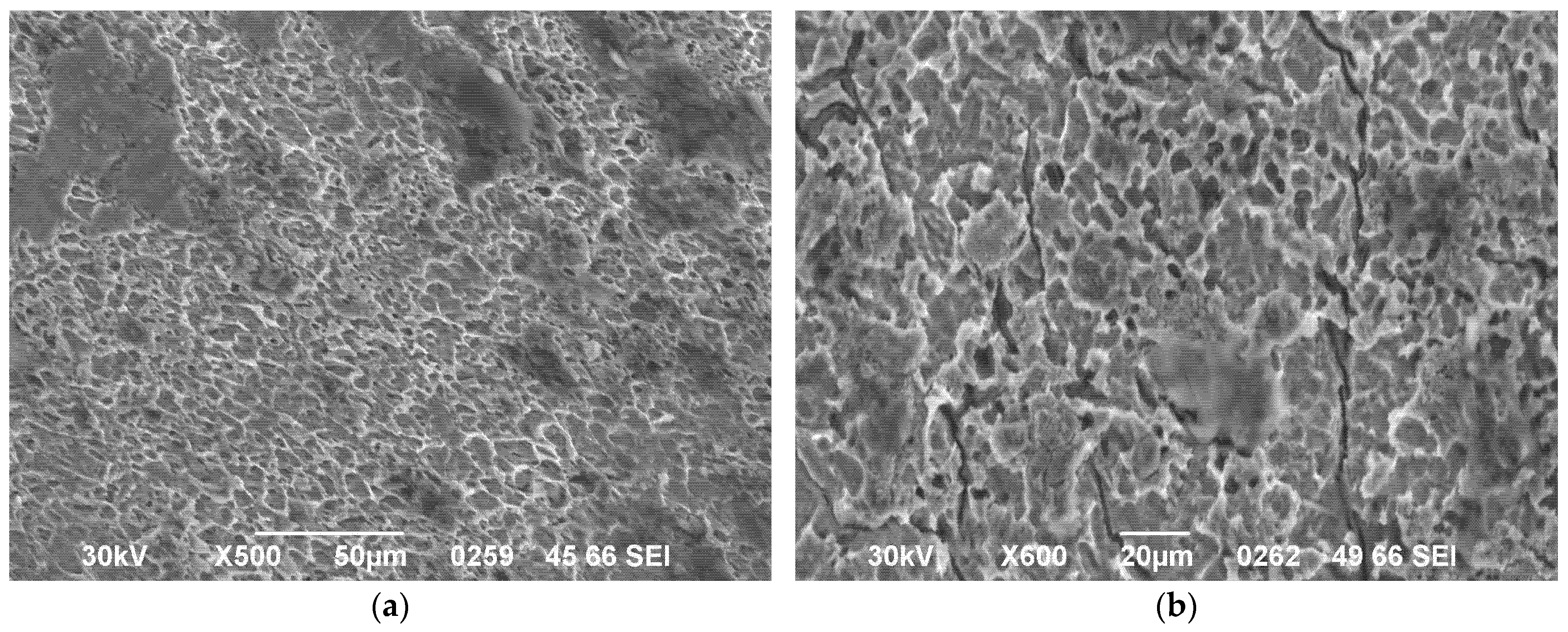
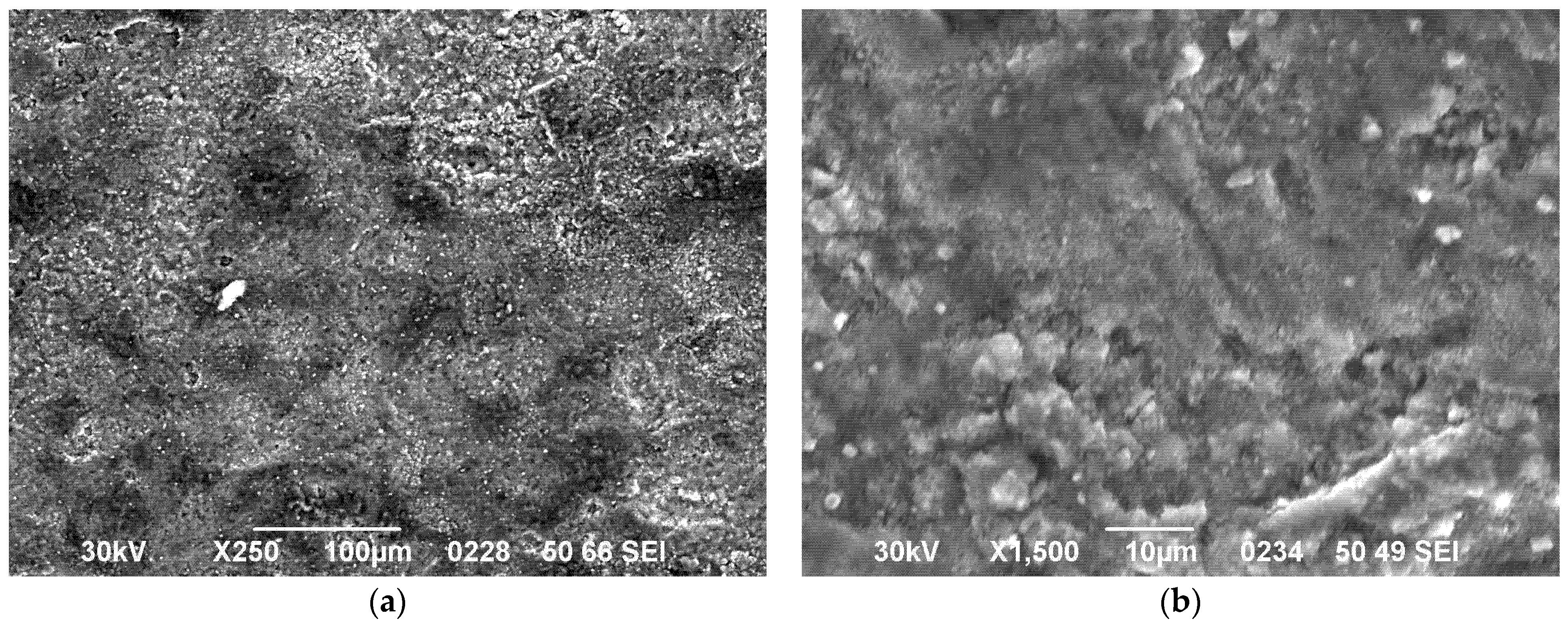
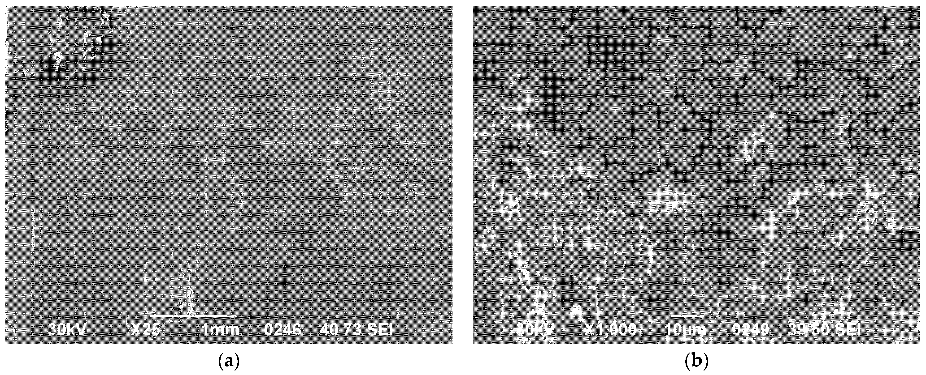
The analysis revealed that corrosion features varied between samples. In Sample No. 1 (Figure 4), taken from the cooler zone of the chamber, the internal surface exhibited relatively uniform morphology with low-density pitting and no signs of cracking or inclusion formation. The shallow pits, typically below 20 µm in depth, suggest limited corrosive interaction under the lower temperature conditions of this region. In the heat-affected zone of Sample No. 2 (approximately 3 mm from the weld), additional cracks were detected (Figure 5b). The internal surface of Sample No. 3 (Figure 6) exhibited finely dispersed inclusions approximately 5 µm in size, appearing as dark contrast regions in the SEM images. Although their exact composition and conductivity could not be confirmed, their morphology suggests the presence of corrosion-related surface deposits or reaction products. In Sample No. 4, no cracks were observed; however, black surface deposits (Figure 7a), presumably reaction products formed during chlorine exposure, were found to protrude above the base surface and exhibited a microcracked morphology.
Overall, macro- and microstructural analyses confirmed chlorine interaction with the chamber material. The damage was non-uniform and manifested primarily as pitting erosion [40,41].

3.3. Wall Thickness Evaluation

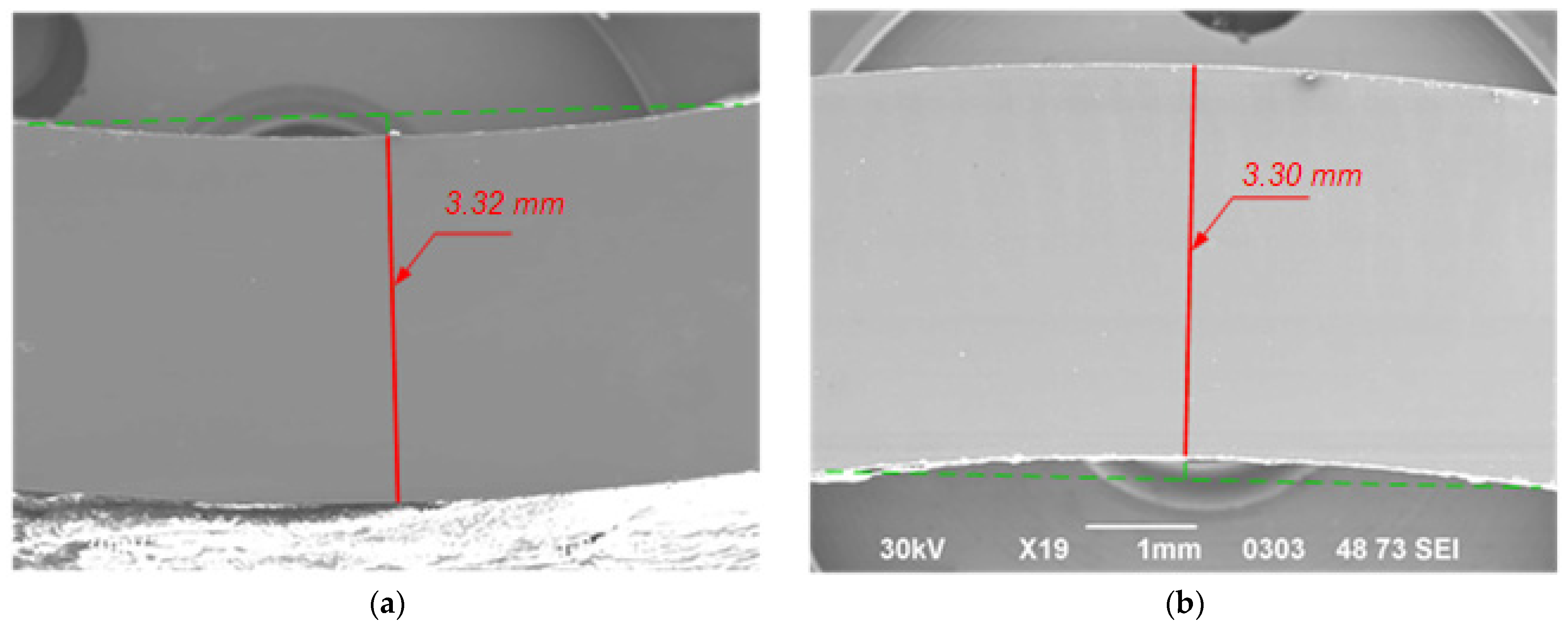
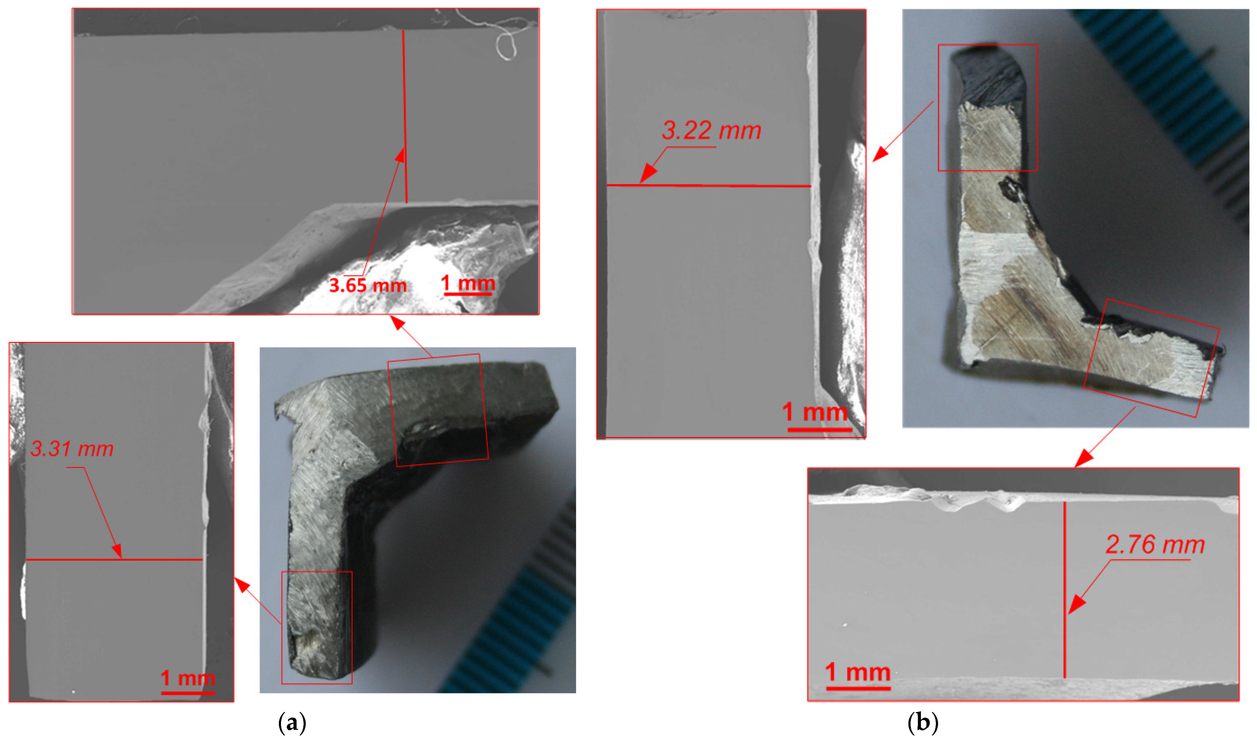
To measure the wall thickness of the reaction chamber and determine the depth of pitting degradation, the end faces of the specimens were subjected to mechanical grinding followed by electrolytic polishing. It is important to note that the initial wall thickness of the tube was taken as 3.85 mm, in accordance with the tolerance specified in GOST 8734-75 [42] (±10%) and the measurements carried out.
The appearance of the polished cross-sections is shown in Figure 8 and Figure 9. Dimensional markings were applied to the images to indicate the measurement points used in the thickness evaluation.
The results of the residual wall thickness measurements obtained from metallographic specimens are summarized in Table 3.
Analysis of the data presented in Table 3 shows that the minimum wall thickness (observed in Sample No. 4) is 2.76 mm, corresponding to the bottom section of the chamber. The wall thickness in Sample No. 3 (3.30 mm) was slightly higher but still indicative of notable material loss in the heater zone. The side wall thickness of Sample No. 2 matched that of Sample No. 1 (3.31–3.32 mm), indicating minimal degradation in the cooler region. The bottom wall of the reaction chamber, as inferred from Sample No. 4, was the most affected, with material thinning exceeding that of all other sections.
Assuming an initial wall thickness of 3.85 mm, the maximum erosion depth was observed in the heater zone (Sample No. 4) and amounted to 1.09 mm, suggesting localized thinning due to prolonged exposure to high temperatures and reactive chlorine species.

3.4. Localized Damage and Structural Changes

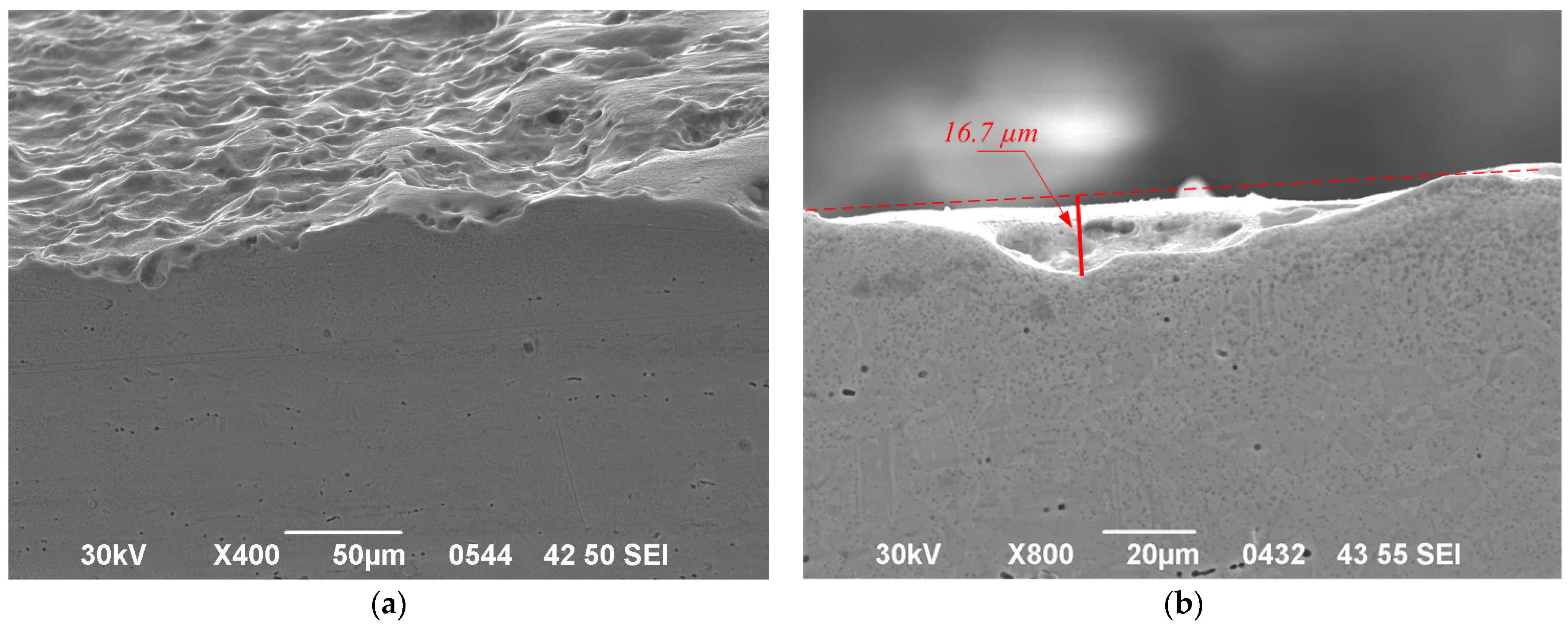
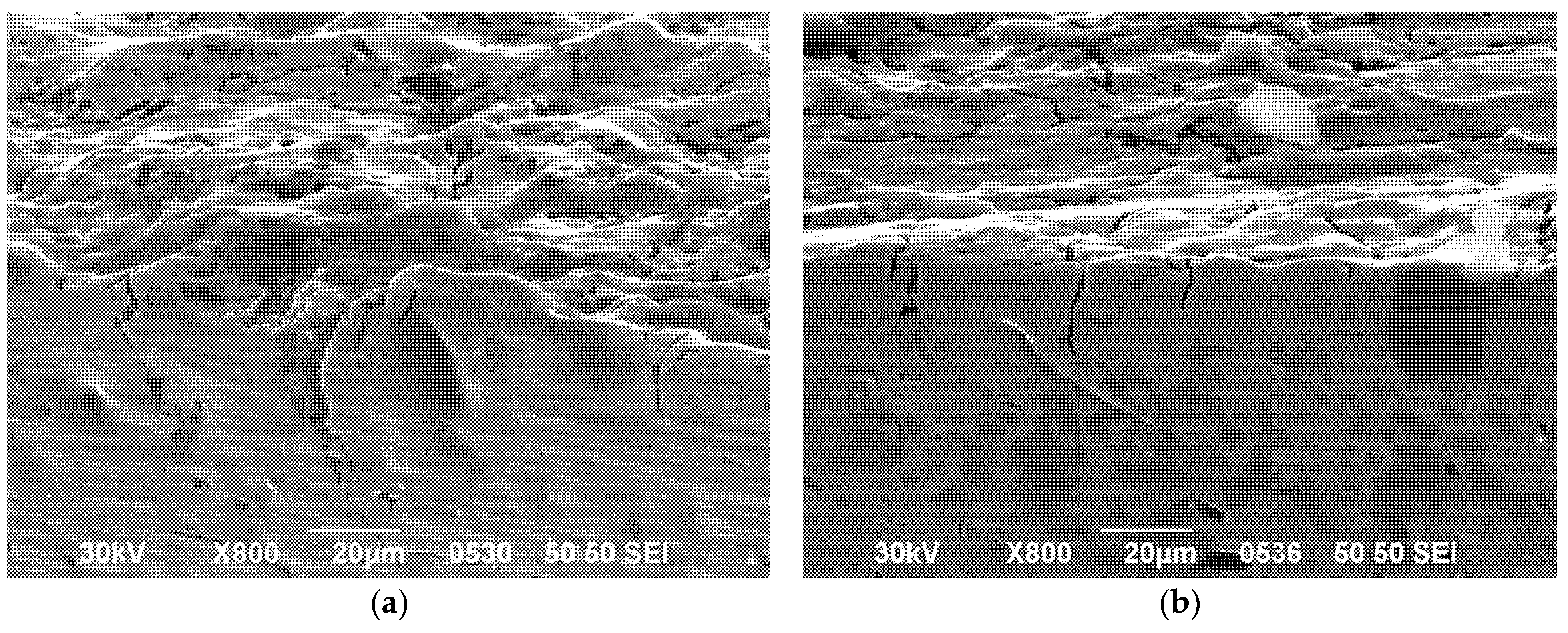
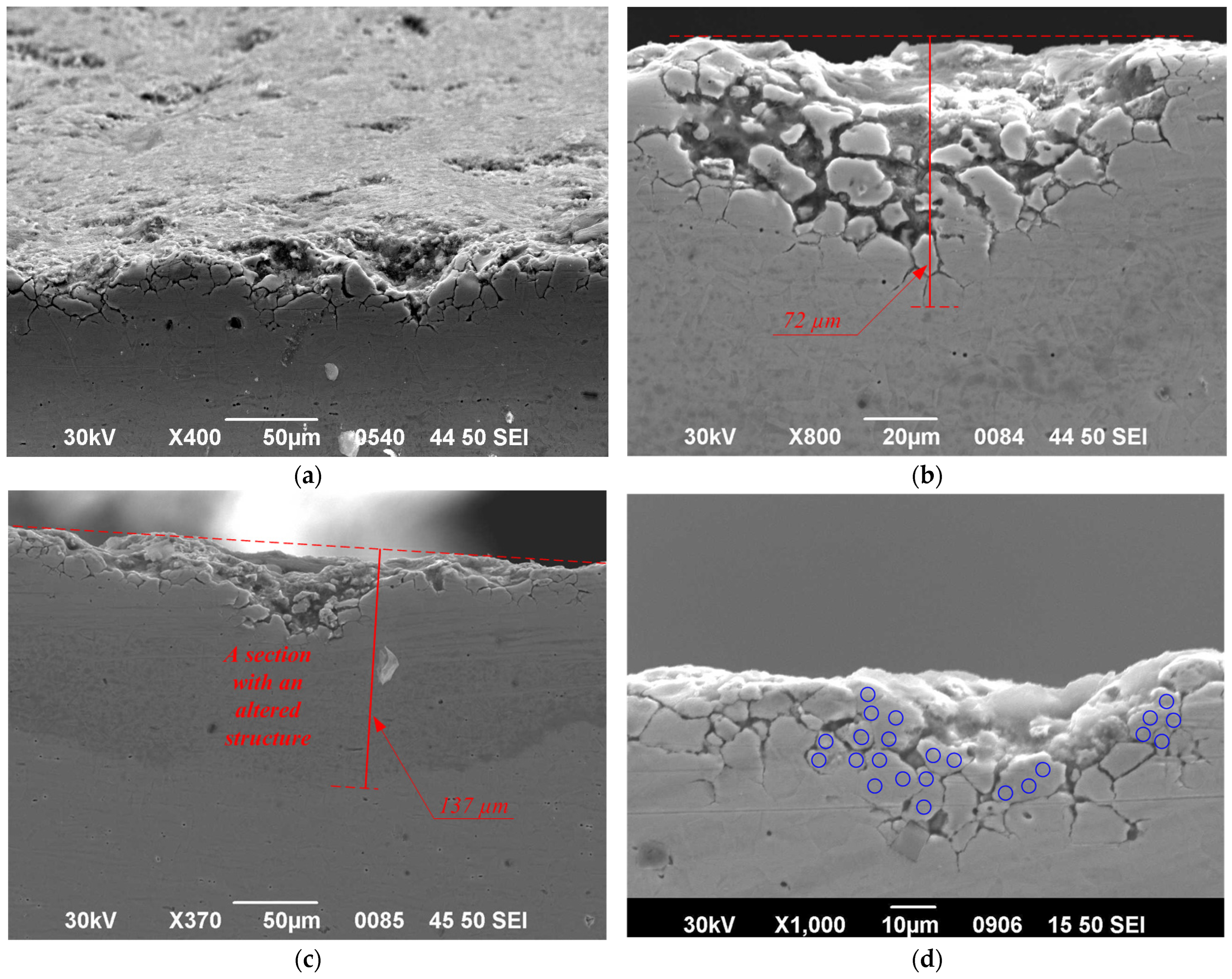
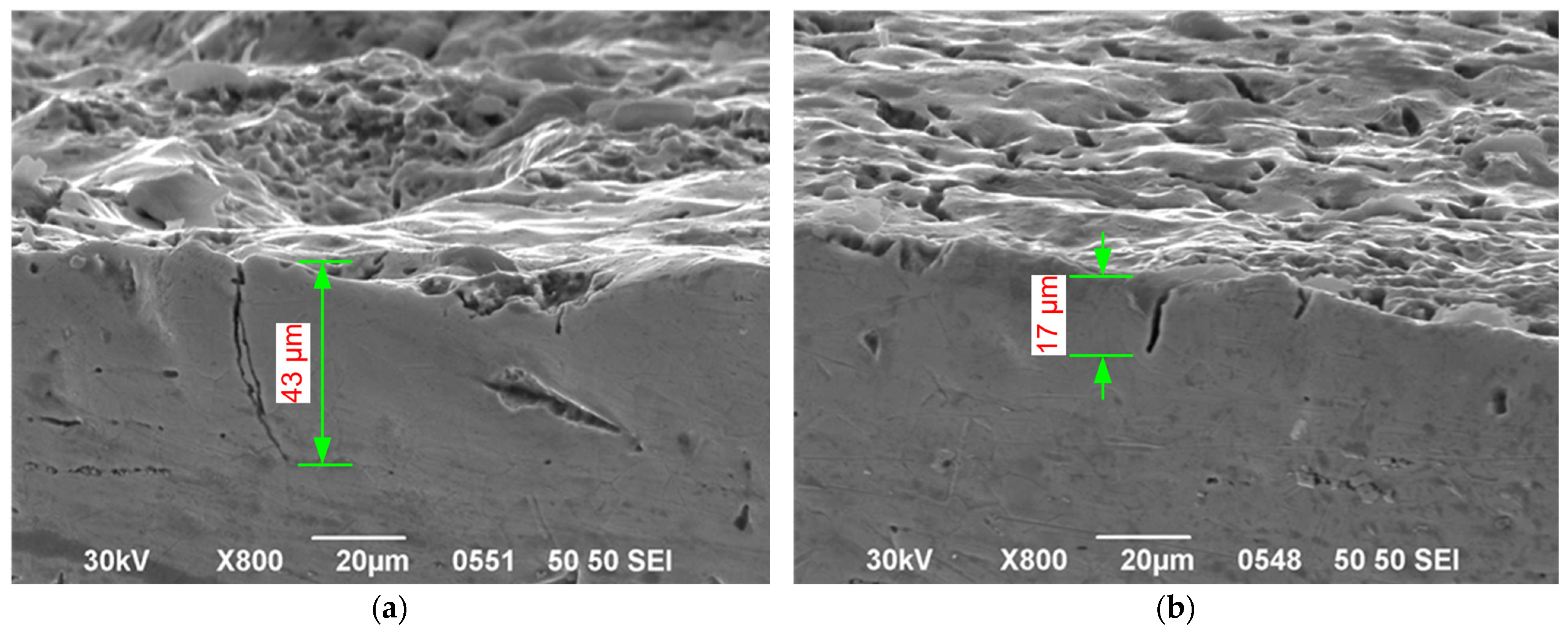
To assess the depth of pitting damage and analyze structural changes in the chamber wall material, the edges of the specimens were subjected to mechanical grinding followed by electrolytic polishing. The resulting images (Figure 10, Figure 11, Figure 12 and Figure 13) provided detailed insight into the damage morphology and zones of localized structural modification.
Sample No. 1 (Figure 10) showed pitting up to 17 µm in depth and 131 µm in width. Samples No. 2 and No. 4 (Figure 11 and Figure 13) displayed characteristic “knife-like” erosion in near-surface regions. Sample No. 3 (Figure 12) was the most affected, with a modified layer up to 140 µm thick and evidence of intergranular corrosion along grain boundaries.
In Figure 12b–d, grain boundaries are visible due to microstructural contrast, indicating zones where structural damage occurred.
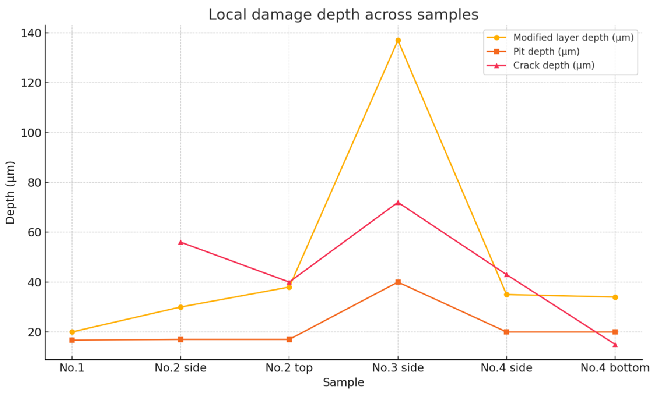
A summary of the measured depths of structural modifications, pits, and cracks for all samples is provided in Table 4.
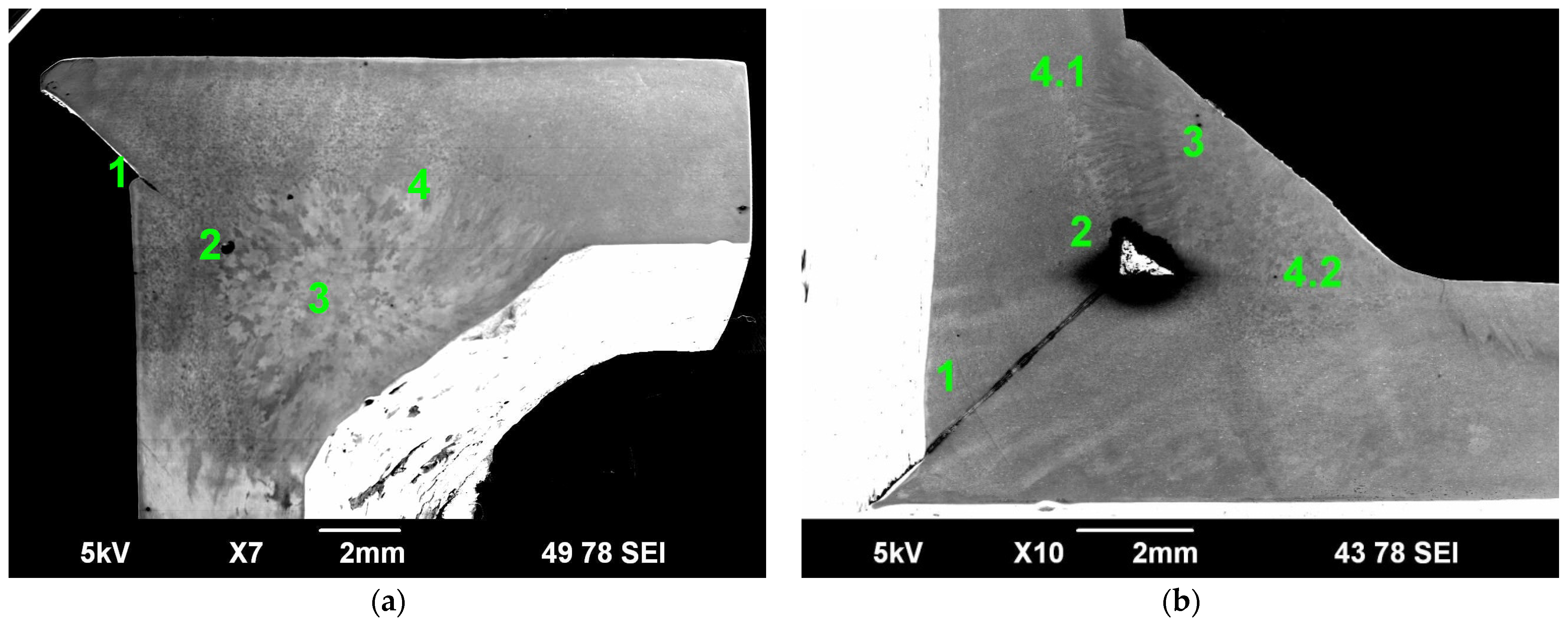
The weld joints of Samples No. 2 and No. 4 (see Figure 14) consist of three characteristic zones: the base material, the heat-affected zone, and the weld metal. For a detailed analysis, four specific areas on the investigated surface were selected for SEM examination. These regions are marked in Figure 14.
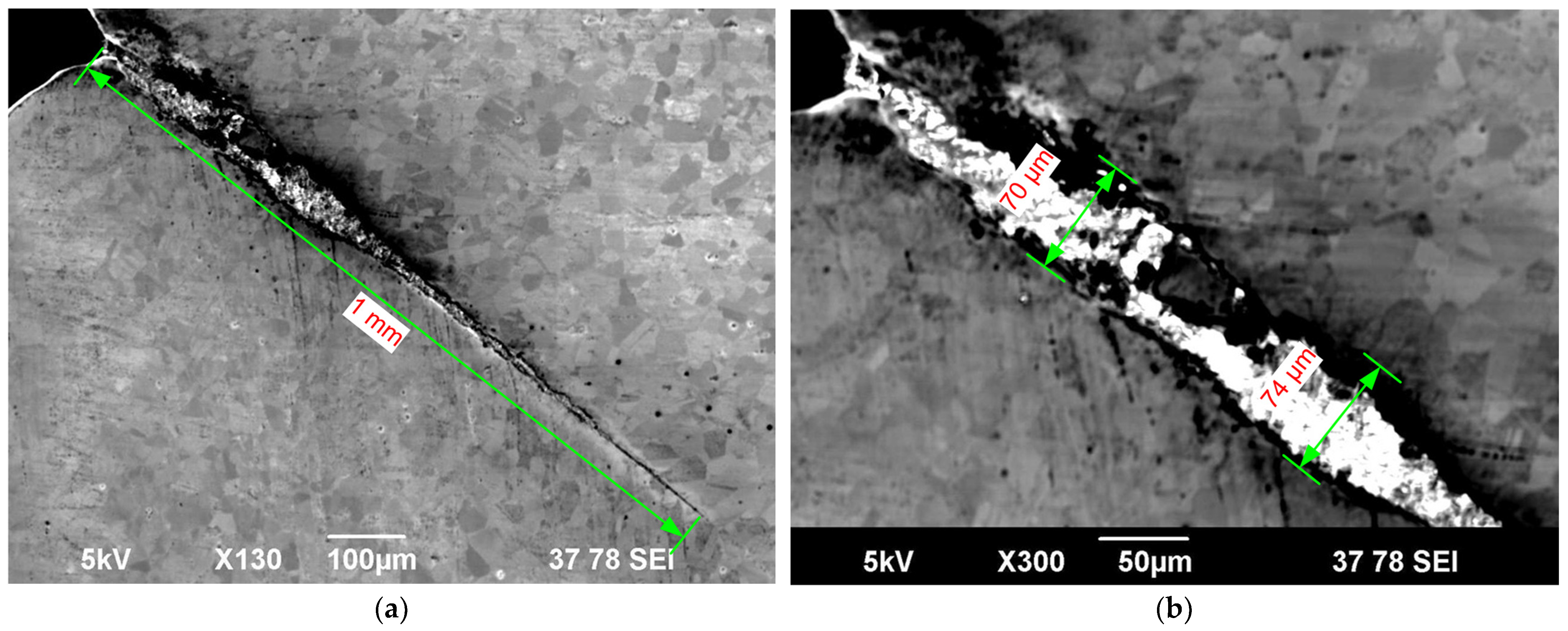
The weld joint of Sample No. 2 contains a region (Zone 1) interpreted as incomplete fusion (lack of penetration) (Figure 15a), with an approximate depth of 1 mm and an average width of 70 μm. Although image quality limits definitive confirmation, the morphology suggests a channel-like feature that could allow chlorine to penetrate between the base metal and weld metal, potentially compromising the integrity of the joint. As shown in Figure 15b, this channel is filled with a non-conductive material, presumably chlorides of steel components.
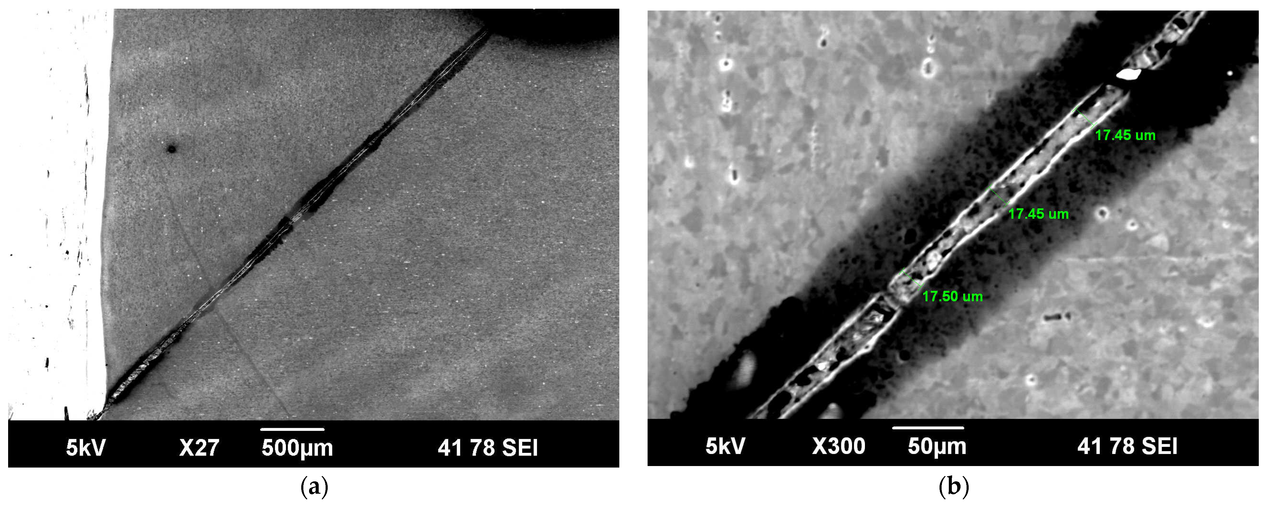
The weld in Sample No. 4 (see Figure 16) also exhibits imprecise edge alignment, resulting in the formation of a narrow channel (~17 µm wide) filled with chloride compounds extending into the weld metal region. At the pipe interface, dark bands are visible (Figure 16b), indicating near-surface structural alterations. The depth of the structurally modified layer in this area averages 35 µm. Similar modified zones were observed in the near-surface investigations of other samples, with Figure 12c offering the most illustrative example.
In the weld root areas of both samples, cavities were observed (highlighted as Zone 2 in Figure 14). Their appearance is shown in Figure 15. Surrounding these cavities, structurally altered zones (3, 4, 4.1, and 4.2) were identified, reaching up to 150 µm in depth in the base metal and up to 400 µm in the weld metal.
Aside from these features, the overall structure of the weld metal in both joints showed no evidence of pores, cracks, or non-metallic inclusions.
The bright phases observed in the crack zones (Figure 15 and Figure 16) and in the weld root region (Figure 17b) are interpreted as corrosion products, most likely chloride-based reaction deposits formed during exposure to chlorine at elevated temperatures. Although their exact chemical composition could not be confirmed due to radiological restrictions on EDS analysis, their presence indicates filling of microvoids and cracks, which may contribute to localized stress concentration and further material embrittlement.

4. Discussion

To assess the degradation behavior of 12Cr18Ni10Ti stainless steel under chlorine exposure and thermal loading, a quantitative analysis was performed using microstructural data. The maximum depths of the modified surface layers, pits, and cracks measured for four representative samples were correlated with their estimated operating temperatures, determined from the known layout of the chlorination chamber: Sample No. 1 (cooler zone) ~350 °C, No. 2 ~400 °C, No. 3 (heater zone) ~1000 °C, and No. 4 ~900 °C. These estimates are consistent with the chamber’s thermal distribution model and previously reported operational data [9,11,12].
As shown in Figure 18, degradation severity increased with temperature. The thickest modified layer (140 µm) and deepest pits (up to 40 µm) occurred in Sample No. 3 (heater zone), confirming that elevated heat accelerates chlorine-induced corrosion. This temperature dependence agrees with high-temperature chlorination studies of stainless steels, which reported rapid breakdown of passive films and enhanced intergranular attack above ~600–700 °C [15,43]. Similar acceleration of surface degradation in chlorine-containing atmospheres has been documented in oxidation studies of AISI 321 and related steels [44,45], where increased oxide volatility promotes penetration of chlorine species.
A second controlling factor was weld integrity. Significant localized damage, including cracks and knife-line attack, developed in Samples No. 2 and No. 4 despite their lower thermal loading. This behavior aligns with reports that incomplete penetration, porosity, and heat-affected zone (HAZ) heterogeneities in welds serve as preferred corrosion initiation sites [46]. Metallurgical investigations of AISI 321 welds show that extensive carbide precipitation and subsequent σ-phase formation in the HAZ reduce local chromium availability and promote intergranular attack. Moreover, filler-metal selection strongly influences susceptibility: pulsed-GTAW studies demonstrated that ERNiCrMo-3 welds introduce deleterious Laves phase, whereas ERNiCrMo-4 provides superior microstructural stability and corrosion performance. The concentration of cracks at weld regions in this study is consistent with these metallurgical observations [47].
Inclusions also played a role in localization. The dark features observed in Samples No. 3 and No. 4 correlate well with TiN inclusions, which have been identified as galvanic pit initiation sites in AISI 321 stainless steel [23,48,49], whereas TiC inclusions remain comparatively inert [50,51]. The linkage of pit initiation to inclusion chemistry explains the transition from shallow, scattered pits in cooler zones to deeper, crack-associated damage in high-temperature weld-adjacent regions.
Taken together, the results indicate that degradation in chlorine is governed by a dual dependence: (i) temperature sets the depth and rate of uniform corrosion, while (ii) microstructural heterogeneity—particularly weld defects and TiN inclusions—dictates localization.
The quantitative assessment of layer, pit, and crack depths across a realistic thermal profile provides new insight into the operational performance of 12Cr18Ni10Ti in high-temperature chlorine environments relevant to JMTR beryllium reflector treatment. Practically, these findings highlight the need for strict weld quality control, prevention of incomplete fusion, optimized filler-metal selection, and effective temperature management to extend the service life of structural components in nuclear chlorination systems.

5. Conclusions

This study provides a comprehensive characterization of the behavior of austenitic stainless steel 12Cr18Ni10Ti under high-temperature chlorination conditions during the treatment of an irradiated beryllium reflector retrieved from the JMTR research reactor. The results demonstrate that under thermal exposure up to 1000 °C in a chlorine-rich atmosphere, the steel primarily undergoes general erosion, with localized pitting and intergranular corrosion observed in thermally stressed regions and welded joints. The most severe degradation was observed in the heating zone, where the wall thickness decreased to 2.76 mm, and a modified surface layer of up to 140 μm was detected for 20 min of exposure. The formation of microcracks and local welding defects further intensified corrosion, creating pathways for chlorine ingress and promoting structural transformations.
These results are of significant practical relevance: they provide well-defined thresholds for the use of 12Cr18Ni10Ti steel in systems designed for the chlorination of activated beryllium materials and establish guidelines for weld quality control and thermal operation limits. The outcomes of this study may, therefore, be applied in the design and safety assessment of similar chlorination systems in the nuclear industry, especially those intended for processing irradiated beryllium components accumulating radionuclides under reactor conditions such as those in JMTR.

Author Contributions

Conceptualization, Y.B. and Y.S.; methodology, Y.S.; formal analysis, Y.S.; investigation, K.S.; resources, Y.B.; data curation, K.S.; writing—original draft preparation, Y.B.; writing—review and editing, K.S.; visualization, Y.B.; supervision, Y.S.; project administration, Y.S.; funding acquisition, Y.S. All authors have read and agreed to the published version of the manuscript.

Funding

This research has been funded by the Committee of Science of the Ministry of Science and Higher Education of the Republic of Kazakhstan, grant number BR24993104.

Data Availability Statement

Data are contained within the article. The original contributions presented in the study are included in the article, further inquiries can be directed to the corresponding author.

Acknowledgments

The authors express their gratitude to specialists of the Material Testing Department of the Institute of Atomic Energy, branch of the National Nuclear Center of the Republic of Kazakhstan, for professional assistance and advice in obtaining the results.

Conflicts of Interest

The authors declare no conflicts of interest.

Abbreviations

The following abbreviations are used in this manuscript:
JMTRJapan Materials Testing Reactor
SEMScanning electron microscopy

References

  1. Fernández-Arias, P.; Vergara, D.; Antón-Sancho, Á. Global Review of International Nuclear Waste Management. Energies 2023, 16, 6215. [Google Scholar] [CrossRef]
  2. Terranova, M.L.; Tavares, O.A.P. Trends and Perspectives on Nuclear Waste Management: Recovering, Recycling, and Reusing. J. Nucl. Eng. 2024, 5, 299–317. [Google Scholar] [CrossRef]
  3. Lee, S.G.; Cheong, J.H. Neutron Activation of Structural Materials of a Dry Storage System for Spent Nuclear Fuel and Implications for Radioactive Waste Management. Energies 2020, 13, 5325. [Google Scholar] [CrossRef]
  4. Tang, W.; Chatzidakis, S.; Schrad, C.M.; Miller, R.G.; Howard, R. Study of Mechanical Properties, Microstructure, and Residual Stresses of AISI 304/304L Stainless Steel Submerged Arc Weld for Spent Fuel Dry Storage Systems. Metals 2024, 14, 262. [Google Scholar] [CrossRef]
  5. Alwaeli, M.; Mannheim, V. Investigation into the Current State of Nuclear Energy and Nuclear Waste Management—A State-of-the-Art Review. Energies 2022, 15, 4275. [Google Scholar] [CrossRef]
  6. Merk, B.; Detkina, A.; Atkinson, S.; Litskevich, D.; Cartland-Glover, G. Innovative Investigation of Reflector Options for the Control of a Chloride-Based Molten Salt Zero-Power Reactor. Appl. Sci. 2021, 11, 6795. [Google Scholar] [CrossRef]
  7. Dylst, K.; Seghers, J.; Druyts, F.; Braet, J. Removing Tritium and Other Impurities During Industrial Recycling of Beryllium from a Fusion Reactor. Fusion Sci. Technol. 2008, 54, 215–218. [Google Scholar] [CrossRef]
  8. Kolbasov, B.N.; Khripunov, V.I.; Biryukov, A.Y. On use of beryllium in fusion reactors: Resources, impurities, and necessity of detritiation after irradiation. Fusion Eng. Des. 2016, 109–111, 480–484. [Google Scholar] [CrossRef]
  9. Suleimenov, N.A.; Kotov, V.M.; Vurim, A.D.; Baklanova, Y.Y. Operating parameters of a direct flow irradiated beryllium chlorination plant. NNC RK Bull. 2020, 1, 12–18. (In Russian) [Google Scholar] [CrossRef]
  10. Kotov, V.; Savchyk, V.; Zorin, B.; Tazhibayeva, I.; Kawamura, H.; Tsuchiya, K.; Druyts, F. Research and development of recycling technology of irradiated beryllium. In Proceedings of the 14th International Conference on Fusion Reactor Materials (ICFRM-14), Sapporo, Japan, 10–11 September 2009. [Google Scholar]
  11. Kotov, V.M.; Supprunov, V.I.; Baklanova, Y.Y.; Vityuk, G.A.; Suraev, A.S. Beryllium chloride plant temperature conditions. NNC RK Bull. 2013, 1, 70–77. (In Russian) [Google Scholar]
  12. Baklanova, Y.Y.; Vurim, A.D.; Kotov, V.M.; Surayev, A.S.; Prozorova, I.V. Work safety during purification of irradiated beryllium by chlorination. J. Phys. Conf. Ser. 2020, 1443, 012018. [Google Scholar] [CrossRef]
  13. GOST 5632-1997; High-Alloy Steels and Corrosion-Resistant, Heat-Resisting and High-Temperature Alloyed Grades. Fushun Special Steel: Fushun, China, 1997; p. 20. Available online: https://www.fushunspecialsteel.ru/upload/userfiles/files/%D0%93%D0%9E%D0%A1%D0%A2%205632_1997%20%D0%B2%D1%8B%D1%81%D0%BE%D0%BA%D0%BE%D0%BB%D0%B5%D0%B3%D0%B8%D1%80%D0%BE%D0%B2%D0%B0%D0%BD%D0%BD%D0%B0%D1%8F%20%D1%81%D1%82%D0%B0%D0%BB%D1%8C%20%D0%B8%20%D0%BA%D0%BE%D1%80%D1%80%D0%BE%D0%B7%D0%B8%D0%BE%D0%BD%D0%BD%D0%BE%D1%81%D1%82%D0%BE%D0%B9%D0%BA%D0%B8%D0%B5%20%D0%B6%D0%B0%D1%80%D0%BE%D0%BF%D1%80%D0%BE%D1%87%D0%BD%D1%8B%D0%B5%20%D0%B8%20%D0%B2%D1%8B%D1%81%D0%BE%D0%BA%D0%BE%D1%82%D0%B5%D0%BC%D0%BF%D0%B5%D1%80%D0%B0%D1%82%D1%83%D1%80%D0%BD%D1%8B%D0%B5%20%D0%BB%D0%B5%D0%B3%D0%B8%D1%80%D0%BE%D0%B2%D0%B0%D0%BD%D0%BD%D1%8B%D0%B5%20%D0%BC%D0%B0%D1%80%D0%BA%D0%B8.pdf (accessed on 19 August 2025).
  14. Lehmusto, J.; Skrifvars, B.J.; Yrjas, P.; Hupa, M. Comparison of potassium chloride and potassium carbonate with respect to their tendency to cause high-temperature corrosion of stainless 304L steel. Fuel Process. Technol. 2013, 105, 98–105. [Google Scholar] [CrossRef]
  15. Liu, G.; Liu, Y.; Cheng, Y.; Li, J.; Jiang, Y. The Intergranular Corrosion Susceptibility of Metastable Austenitic Cr–Mn–Ni–N–Cu High-Strength Stainless Steel under Various Heat Treatments. Materials 2019, 12, 1385. [Google Scholar] [CrossRef]
  16. Nowik, K.; Zybała, R.; Sztorch, B.; Oksiuta, Z. Corrosion Behavior of Ferritic 12Cr ODS and Martensitic X46Cr13 Steels in Nitric Acid and Sodium Chloride Solutions. Materials 2024, 17, 3466. [Google Scholar] [CrossRef] [PubMed]
  17. Jeong, J.-Y.; Jeong, C.; Kim, Y.-J.; Jang, C. Effect of Stress Magnitude on Pit Growth Rate of 304 Austenitic Stainless Steel in Chloride Environments. Metals 2021, 11, 1415. [Google Scholar] [CrossRef]
  18. Wang, L.; Zanna, S.; Mercier, D.; Maurice, V.; Marcus, P. Early-stage surface oxidation of the equiatomic CoCrFeMnNi high entropy alloy studied in situ by XPS. Corros. Sci. 2023, 220, 111310. [Google Scholar] [CrossRef]
  19. Liu, Q.; Wang, C.; Qian, J.; Pessu, F. Investigation of the early stage corrosion characteristics of molten (nitrate) salt–oxide–metal interfaces, and the links to interfacial thermo-mechanical stress. Corros. Sci. 2023, 220, 111282. [Google Scholar] [CrossRef]
  20. Migai, L.L.; Taritsyna, T.A. Corrosion Resistance of Materials in Chlorine and Its Compounds; Metallurgy: Moscow, Russia, 1976; pp. 1–120. (In Russian) [Google Scholar]
  21. Tomashov, N.D. Theory of Corrosion and Protection of Metals: The Science of Corrosion; Macmillan: New York, NY, USA, 1966; pp. 1–672. [Google Scholar]
  22. Gerard, A.Y.; Kautz, E.J.; Schreiber, D.K.; Han, J.; McDonnell, S.; Ogle, K.; Lu, P.; Saal, J.E.; Frankel, G.S.; Scully, J.R. The role of chromium content in aqueous passivation of a non-equiatomic Ni38Fe20CrxMn21-0.5xCo21-0.5x multi-principal element alloy (x = 22, 14, 10, 6 at%) in acidic chloride solution. Acta Mater. 2023, 245, 118607. [Google Scholar] [CrossRef]
  23. Tiamiyu, A.A.; Eduok, U.; Szpunar, J.A.; Zeng, C.H. Corrosion Behavior of Metastable AISI 321 Austenitic Stainless Steel: Investigating the Effect of Grain Size and Prior Plastic Deformation on Its Degradation Pattern in Saline Media. Sci. Rep. 2019, 9, 12116. [Google Scholar] [CrossRef] [PubMed]
  24. Narivs’kyi, O.; Atchibayev, R.; Kemelzhanova, A.; Yar-Mukhamedova, G.; Snizhnoi, G.; Subbotin, S.; Beisebayeva, A. Mathematical Modeling of the Corrosion Behavior of Austenitic Steels in Chloride-Containing Media during the Operation of Plate-Like Heat Exchangers. Eurasian Chem. Technol. J. 2022, 24, 295–302. [Google Scholar] [CrossRef]
  25. Snizhnoi, G.V.; Snizhnoi, V.L. Magnetometric assessment of the influence of chemical elements on the corrosion of austenitic Fe-Cr-Ni alloys. Mater. Sci. 2024, 60, 91–96. [Google Scholar] [CrossRef]
  26. Narivskyi, O.E.; Belikov, S.B.; Subbotin, S.A.; Pulina, T.V. Influence of chloride-containing media on the pitting resistance of AISI 321 steel. Mater. Sci. 2021, 57, 291–297. [Google Scholar] [CrossRef]
  27. Nejati, S.; Tavangar, R.; Pour-Ali, S.; Hejazi, S. Improved Resistance to Chloride-Induced Corrosion through the Combined Influence of Surface Nanocrystallization and Thermal Oxidation Treatments on AISI 321 Stainless Steel. Mater. Chem. Phys. 2023, 309, 128404. [Google Scholar] [CrossRef]
  28. Kawamura, H.; Sakamoto, N.; Tatenuma, K. Reprocessing Technology Development for Irradiated Beryllium. In Proceedings of the International Conference on Nuclear Engineering (ICONE), Kyoto, Japan, 23–27 April 1995; pp. 261–268. [Google Scholar]
  29. Inaba, Y.; Ishihara, M.; Niimi, M.; Kawamura, H. Present status of refurbishment and irradiation technologies in JMTR. J. Nucl. Mater. 2011, 417, 1348–1351. [Google Scholar] [CrossRef]
  30. Mukhamedov, N.; Toleubekov, K.; Vityuk, G.; Bekmuldin, M.; Dolzhikov, S. Decommissioning of the BN-350 Fast Neutron Reactor: History Review and Current Status. Energies 2025, 18, 3486. [Google Scholar] [CrossRef]
  31. Mukhamedov, N.; Baklanov, V.; Moldagulov, M.; Toleubekov, K.; Surayev, A.; Yagudin, A.; Kanatnikov, S. The BN-350 Reactor Decommissioning: Quantitative Analysis and Prospects for Solid Radioactive Waste Management. Energies 2025, 18, 4651. [Google Scholar] [CrossRef]
  32. Koyanbayev, Y.T.; Skakov, M.K.; Batyrbekov, E.G.; Deryavko, I.I.; Sapatayev, Y.Y.; Kozhahmetov, Y.A. The Forecasting of Corrosion Damage of Structural Materials during Dry Long-Term Storage of RD BN-350 SNF with CC-19 SFA. Sci. Technol. Nucl. Ins. 2019, 2019, 1293060. [Google Scholar] [CrossRef]
  33. Koyanbayev, Y.T.; Skakov, M.K.; Ganovichev, D.A.; Martynenko, Y.A.; Sitnikov, A.A. Simulation of the Thermal Conditions of Cask with Fuel Assemblies of BN-350 Reactor for Dry Storage. Sci. Technol. Nucl. Ins. 2019, 2019, 3045897. [Google Scholar] [CrossRef]
  34. Koyanbayev, Y. Applying the Hollomon-Jaffe parameter to predict changes in mechanical properties of irradiated austenitic chromium-nickel steels during isothermal exposure. AIMS Mater. Sci. 2024, 11, 216–230. [Google Scholar] [CrossRef]
  35. Dorn, C.K.; Tsuchiya, K.; Kawamura, H.; Hashiguchi, D.H.; Sayer, A.B.; Haws, W.J. Material Selection for Extended Life of the Beryllium Reflectors in the JMTR. In Proceedings of the International Symposium on Materials Testing Reactors, Oarai, Japan, 16–17 July 2008; JAEA Oarai R&D Center: Oarai, Japan, 2008; pp. 59–65. [Google Scholar]
  36. Baklanova, Y. Studying the Decontamination Process of an Irradiated Beryllium Reflector in a Chlorine Environment. PLoS ONE 2025, 20, e0322723. [Google Scholar] [CrossRef]
  37. GOST 14771-76; Arc Welding in Protective Gas. Welded Joints. Basic Types, Design Elements, and Dimensions. Standards Publishing House: Strathfield South, Australia, 1977. Available online: https://auremo.biz/gosts/gost-14771-76.html (accessed on 19 August 2025).
  38. GOST R 50.05.09-2021; Conformity Assessment in the Form of Control. Unified Methods. Capillary Control. Standartinform: Moscow, Russia; p. 32. Available online: https://files.stroyinf.ru/Data2/1/4293732/4293732617.htm (accessed on 19 August 2025).
  39. GOST 18442-80; Non-Destructive Testing. Dye Penetrant Methods. General Requirements. USSR State Committee for Standards: Moscow, Russia, 1980. Available online: https://acnkru.ru/wp-content/uploads/2018/07/GOST-18442-80.pdf (accessed on 19 August 2025).
  40. Silva, R.; Kugelmeier, C.L.; Vacchi, G.S.; Martins Junior, C.B.; Dainezi, I.; Afonso, C.R.M.; Mendes Filho, A.A.; Rovere, C.A.D. A comprehensive study of the pitting corrosion mechanism of lean duplex stainless steel grade 2404 aged at 475 °C. Corros. Sci. 2021, 191, 109738. [Google Scholar] [CrossRef]
  41. Messinese, E.; Casanova, L.; Paterlini, L.; Capelli, F.; Bolzoni, F.; Ormellese, M.; Brenna, A. A Comprehensive Investigation on the Effects of Surface Finishing on the Resistance of Stainless Steel to Localized Corrosion. Metals 2022, 12, 1751. [Google Scholar] [CrossRef]
  42. GOST 8734-75; Seamless Steel Tubes Cold Deformed. Range. State Committee of Standards of the USSR: Moscow, Russia, 1975. Available online: https://files.stroyinf.ru/Data1/8/8429/index.htm (accessed on 18 September 2025).
  43. Moura, V.; Kina, A.Y.; Tavares, S.S.M.; Pardal, J.M.; da Silva, M.R. Influence of Stabilization Heat Treatments on Microstructure, Hardness and Intergranular Corrosion Resistance of the AISI 321 Stainless Steel. J. Mater. Sci. 2008, 43, 536–540. [Google Scholar] [CrossRef]
  44. Xu, L.; Shao, C.; Tian, L.; Zhang, J.; Han, Y.; Zhao, L.; Jing, H. Intergranular Corrosion Behavior of Inconel 625 Deposited by CMT/GTAW. Corros. Sci. 2022, 201, 110295. [Google Scholar] [CrossRef]
  45. Alharbi, S.O.; Ahmad, S.; Gul, T.; Khan, M.A.; Aslam, M. The Corrosion Behavior of Low Carbon Steel (AISI 1010) Influenced by Grain Size through Microstructural Mechanical. Sci. Rep. 2024, 14, 5098. [Google Scholar] [CrossRef]
  46. Ibrahim, M.; Nasir, M.; Rahman, M.; Aung, N.N. Effects of Welding Defects on Corrosion Behavior of Stainless Steel in Chloride Solution. Mater. Sci. Eng. A 2009, 508, 64–69. [Google Scholar] [CrossRef]
  47. Ramkumar, K.D.; Pavan, B.; Chandrasekar, V. Development of Improved Microstructural Traits and Mechanical Integrity of Stabilized Stainless Steel Joints of AISI 321. J. Manuf. Process. 2018, 32, 582–594. [Google Scholar] [CrossRef]
  48. Leban, M.B.; Tisu, R. The Effect of TiN Inclusions and Deformation-Induced Martensite on the Corrosion Properties of AISI 321 Stainless Steel. Eng. Fail. Anal. 2013, 33, 430–438. [Google Scholar] [CrossRef]
  49. Dehgahi, S.; Shahriari, A.; Odeshi, A.; Mohammadi, M. Influence of Ti Content on High Strain Rate Mechanical and Corrosion Behavior of Additively Manufactured Maraging Steels. J. Mater. Eng. Perform. 2023, 32, 1169–1184. [Google Scholar] [CrossRef]
  50. Pardo, A.; Merino, M.C.; Coy, A.E.; Viejo, F.; Carboneras, M.; Arrabal, R. Influence of Ti, C and N Concentration on the Intergranular Corrosion Behaviour of AISI 316Ti and 321 Stainless Steels. Acta Mater. 2007, 55, 2239–2251. [Google Scholar] [CrossRef]
  51. Šípová, M.; Marušáková, D.; Aparicio, C.; Procházka, J.; Halodová, P. A study on the corrosion behaviour of stainless steel 08Cr18Ni10Ti in supercritical water. Corros. Sci. 2023, 211, 110853. [Google Scholar] [CrossRef]
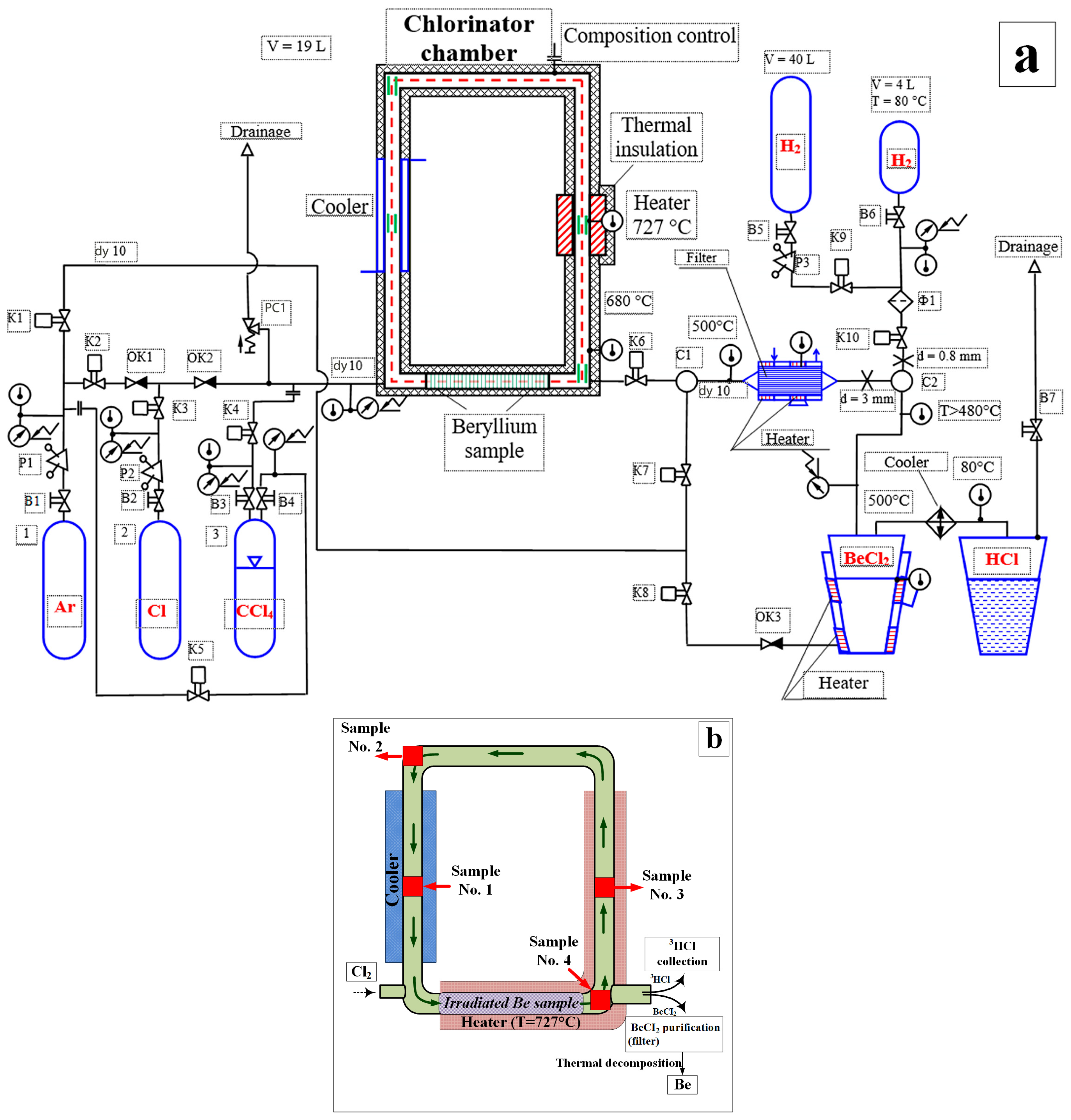
Figure 1. Schematic layout of the high-temperature chlorination chamber (a) and positions of extracted samples for metallographic examination (b).
Metals 15 01052 g001
Figure 2. External view of the studied chlorinator elements: (a) section located at the cooler position; (b) section located at the heater position.
Metals 15 01052 g002
Figure 3. Macroscopic image of the internal surfaces of the tested specimens after chlorination: (a) Sample No. 1—cooler zone; (b) Sample No. 2—weld in cooler zone; (c) Sample No. 3—heater zone; (d) Sample No. 4—weld in heater zone.
Metals 15 01052 g003
Figure 4. Internal surface of Sample No. 1: (a) under magnification of ×130; (b) under magnification of ×500.
Metals 15 01052 g004
Figure 5. Internal surface of Sample No. 2: (a) base metal region; (b) heat-affected zone near the weld.
Metals 15 01052 g005
Figure 6. Internal surface of Sample No. 3: (a) under magnification of ×250; (b) under magnification of ×1500.
Metals 15 01052 g006
Figure 7. Internal surface of Sample No. 4: (a) base metal region; (b) heat-affected zone near the weld.
Metals 15 01052 g007
Figure 8. Cross-section of the reaction chamber wall: (a) Sample No. 1; (b) Sample No. 3.
Metals 15 01052 g008
Figure 9. Longitudinal section of the reaction chamber wall: (a) Sample No. 2; (b) Sample No. 4.
Metals 15 01052 g009
Figure 10. Near-surface layer of the cross-section of Sample No. 1: (a) general view of the analyzed area; (b) depth of localized damage.
Metals 15 01052 g010
Figure 11. Near-surface layer of the longitudinal section of Sample No. 2: (a) side wall; (b) top surface.
Metals 15 01052 g011
Figure 12. Near-surface layer of the cross-section of Sample No. 3: (a) general view of the degraded surface layer (×400); (b) modified layer (~72 µm) with highlighted grain boundaries (×800); (c) altered structure zone (×370); (d) analysis points marked for enhanced visualization (×1000).
Metals 15 01052 g012
Figure 13. Near-surface layer of the longitudinal section of Sample No. 4: (a) side wall; (b) bottom surface.
Metals 15 01052 g013
Figure 14. External appearance of the welded joints in the chamber wall: (a) Sample No. 2; (b) Sample No. 4.
Metals 15 01052 g014
Figure 15. Weld joint area of Sample No. 2: (a) region with incomplete fusion (lack of penetration); (b) surface view of a channel filled with non-conductive material.
Metals 15 01052 g015
Figure 16. Weld joint area of Sample No. 4: (a) external view of the incomplete fusion region (lack of penetration); (b) near-surface structural changes in the weld zone.
Metals 15 01052 g016
Figure 17. SEM images of the weld root: (a) Sample No. 2; (b) Sample No. 4.
Metals 15 01052 g017
Figure 18. Depth of localized corrosion damage (modified layer, pits, and cracks) in 12Cr18Ni10Ti samples.
Metals 15 01052 g018
Table 1. Chemical composition of JMTR reactor beryllium, at.%.
ElementBeBeOFeCAlSiMgNClNiOthers
Content>98.3<1.3<0.16<0.15<0.10<0.08<0.05<0.05<0.04<0.03<0.08
Table 2. Chemical composition of the 12Cr18Ni10Ti grade steel, wt.%. Adapted from ref. [26].
MaterialFeCCrNiTiSiMnPS
12Cr18Ni10TiBase0.1217.0010.660.500.801.670.030.02
Table 3. Wall thickness of the chlorination chamber.
SampleNo. 1No. 2No. 3No. 4
SideTop SideBottom
Wall
thickness, mm
3.32 ± 0.0053.31 ± 0.0053.65 ± 0.0053.30 ± 0.0053.22 ± 0.0052.76 ± 0.005
Table 4. Results of localized damage depth measurements for 12Cr18Ni10Ti steel.
SampleNo. 1No. 2No. 3No. 4
SideTop SideBottom
Maximum depth of modified layer (µm)2030381373534
Maximum pit depth (µm)16.71717402020
Maximum crack depth (µm)No cracking was observed5640724315
Disclaimer/Publisher’s Note: The statements, opinions and data contained in all publications are solely those of the individual author(s) and contributor(s) and not of MDPI and/or the editor(s). MDPI and/or the editor(s) disclaim responsibility for any injury to people or property resulting from any ideas, methods, instructions or products referred to in the content.