1. Introduction
Friction stir welding (FSW) is a proven solid-state welding technique that effectively reduces or eliminates issues commonly associated with conventional fusion welding methods, such as porosity and high residual stress [
1,
2]. With the advancement of FSW, several derivative techniques, including friction stir spot welding (FSSW), friction stir repairing (FSR), and friction stir lap welding (FSLW), have also been widely used in industrial applications in recent years [
3]. FSLW has successfully joined dissimilar material combinations, including Al/Al, Al/Fe, Al/Mg, and Al/Ti [
4,
5,
6,
7]. Studies indicate that enhancing material flow and eliminating weld defects are crucial for improving the FSLW joint strength [
8,
9]. To address this, ultrasonic vibration has been introduced to assist FSLW, improving material flow and reducing defect formation through the acoustoplastic effect [
10,
11].
To date, many researchers have investigated the influence of ultrasonic assistance on the macro-/micro-structural evolution during FSW/FSLW. Lyu et al. [
12] identified a preheating effect induced by ultrasonic vibration, which increased the material strain of FSW and refined the grain size in the nugget zone. Zhu et al. [
13] demonstrated that ultrasonic vibration significantly accelerated the material flow of FSW and eliminated the tunnel defects in the nugget zone. Hu et al. [
14,
15] found that ultrasonic assistance reduced the density of geometrically necessary dislocations and residual stress in the nugget zone, thereby improving the FSW performance. Padhy et al. [
16] investigated the recrystallization fractions in the nugget zone of Al-6061 and observed that ultrasonic vibration induced subgrain formation during FSW. Tian et al. [
17] found that superimposing ultrasonic vibration on 2195 Al-Li alloys refined the grain size and enhanced precipitate nucleation, improving the mechanical properties of the FSW joint. Liu et al. [
18] achieved high-quality dissimilar Al/Fe FSLW with ultrasonic assistance, noting that the ultrasonic vibration effectively increased the volume of plastic flow materials and expanded the welding process window, thus enhancing the mechanical interlocking between Al and Fe. Zhai et al. [
19] studied the ultrasonic effect of dissimilar Al/Mg alloys on FSLW, revealing that ultrasonic vibration reduced the flow stress of the materials and enhanced Al/Mg mixing. Yu et al. [
20] applied ultrasonic-assisted FSLW to dissimilar Al/Ti alloys, showing that ultrasonic vibration improved the flowability of weld metals, limited the formation of intermetallic compounds at the Al/Ti interface, and increased the joint shear tensile strength.
While the aforementioned studies focused on the feasibility and advantages of ultrasonic-assisted FSLW, the parameters of ultrasonic source (i.e., the ultrasonic power, amplitude, and frequency) were consistently held constant and thus overlooked. However, these ultrasonic parameters, particularly the ultrasonic power, played a crucial role in FSLW behavior. According to Ji et al. [
21], the ultrasonic power altered the material flow behavior and the weld efficiency. Within an optimal range, increasing the ultrasonic power improved joint quality. Specifically, raising the ultrasonic power from 800 W to 1600 W enhanced the shear tensile strength of dissimilar Al/Mg FSLW joints. In addition, Liu et al. [
22] analyzed the ultrasonic power effect on dissimilar Al/Fe FSLW joints, demonstrating that increasing the ultrasonic power from 0 W to 500 W improved the joint surface morphology, strengthened the mechanical and intermetallic bonding of Al/Fe, and elevated the joint failure load. However, further increases in ultrasonic power (700 W) deteriorated the weld quality. This occurred because the enhanced material softening induced by the ultrasonic vibration failed to counteract the reduction in frictional heat generation caused by the antifriction effect.
It follows that the ultrasonic power exerts a complex effect on the weld performance of FSLW joints with dissimilar materials, warranting additional experimental data. Notably, while Ji at al. [
21] and Liu et al. [
22] focus on dissimilar Al/Fe and Al/Mg joints, dissimilar Al/Al FSLW joints remain unexplored. To address this gap, dissimilar materials, namely Al-7075 and Al-5052, were joined using FSLW by varying the ultrasonic powers in the present work. The microstructural evolution and mechanical properties were systematically analyzed to elucidate the ultrasonic power effect on the performance of dissimilar Al/Al FSLW joints.
2. Materials and Methods
In this study, 3 mm thick cold-rolled plates of Al-7075 and Al-5052 were used as the base metals, and
Table 1 lists their nominal chemical compositions (data obtained from the manufacture’s certificate). The tensile properties of the above base metals are shown in
Table 2.
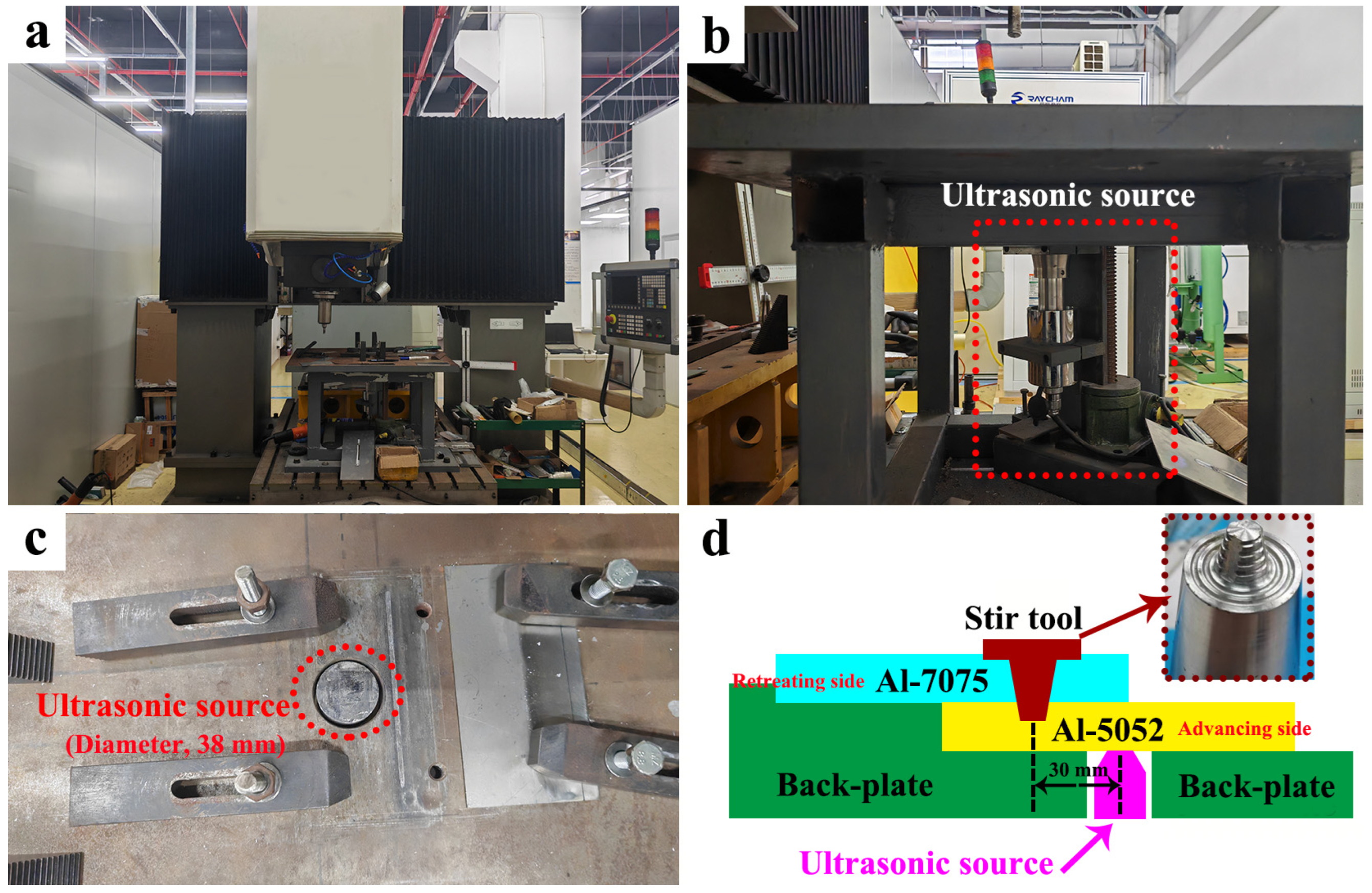
The weld equipment (FSLW, HT-JM25×15/2, AEE, Suzhou, China) is shown in
Figure 1a, with detailed views of the ultrasonic source (i.e., ultrasonic-assisted facility) provided in
Figure 1b,c. The ultrasonic source was fixed beneath the back-plate (
Figure 1b), and its head was inserted into the back-plate through a pre-fabricated hole (
Figure 1c). The head of the ultrasonic source was 38 mm in diameter, and the ultrasonic frequency and amplitude were kept as 20 kHz and 20 μm, respectively.
Figure 1d illustrates the FSLW schematic: the Al-7075 plate was positioned on top of Al-5052 plates, with the ultrasonic source pressing onto the Al-5052 plate (on the advancing side). The H13 stir tool featured a shoulder diameter of 13 mm and a 5.0 mm long conical pin, with root and tip diameters of 5 and 3 mm, respectively. During FSLW, the distance between the ultrasonic source and weld centerline was maintained at 30 mm, and three ultrasonic power levels were employed: 0 W (no ultrasonic assistance), 300 W, and 600 W. Other parameters remained constant: a rotational speed of 800 rpm, a weld speed of 50 mm/min, a plunge depth of 0.2 mm, and a tool tilt angle of 1°.
Note: to maximize the ultrasonic effect, the distance between the ultrasonic source and the weld centerline should be as short as possible. Additionally, a pre-fabricated hole in the back-plate is required to accommodate the ultrasonic source. If the distance is reduced to below 25 mm, the stir tool could press the weld plate into this hole and damage the ultrasonic source. Therefore, a distance of 30 mm was selected to ensure operational safety in this work.
To analyze the microstructural characteristics of dissimilar aluminum FSLW joints, optical microscopy (OM, Olympus-DSX-500, Olympus, Tokyo, Japan), scanning electron microscopy (SEM, FEI-Quanta-600, FEI, Portland, OR, USA), electron back-scattered diffraction (EBSD, FEI-Quanta-600, FEI, Portland, OR, USA), and transmission electron microscopy (TEM, FEI-Tecnai-G20, FEI, Portland, OR, USA) were employed. For OM observation, the FSLW joints were mechanically polished and etched with Keller’s reagent (HF:HCL:HNO3:H2O volume ratio = 2:3:5:90). The samples for SEM analysis, however, were only mechanically polished to prevent the dislodging of second-phase particles during etching. The secondary electron mode of SEM was used. EBSD was used to quantify both the grain size and fraction of high-angle grain boundaries in the nugget zone, and the EBSD samples were electropolished in a perchloric acid–ethanol solution (HCLO4:C2H5OH volume ratio = 1:9) using a scanning step size of 0.2 µm. TEM was utilized to observe the dislocations, grains, and second-phase particles in both the nugget zone and the base metals. The TEM samples were jet electropolished at −25 °C in a nitric acid–methanol solution (HNO3:CH3OH volume ratio = 7:3).
The FM-700 Vickers hardness tester (HV, FM-700, FUTURE-Tech, Tokyo, Japan) was employed to measure the hardness distribution across the entire joint, and indentations were made along the line at mid-thickness through the upper Al-7075/lower Al-5052 plate, traversing from the retreating side to the advancing side. Each measurement line contained 30–40 points spaced 0.5 mm apart. The test was performed under a 50 gf load and 5 s dwell time. Moreover, the mechanical performance of the FSLW joint was evaluated using a shear tensile test (TS, Instron-5969, Instron, Shanghai, China). Specimens were cut perpendicular to the FSLW direction with a gauge measuring 40 mm × 10 mm. The shear tensile test was conducted at a constant crosshead speed of 1.5 mm/min, and the peak shear tensile load value represented the average of three tests per FSLW joint. Failure behavior was subsequently analyzed using OM and SEM.
3. Results and Discussion
The microstructures of the base metals are shown in
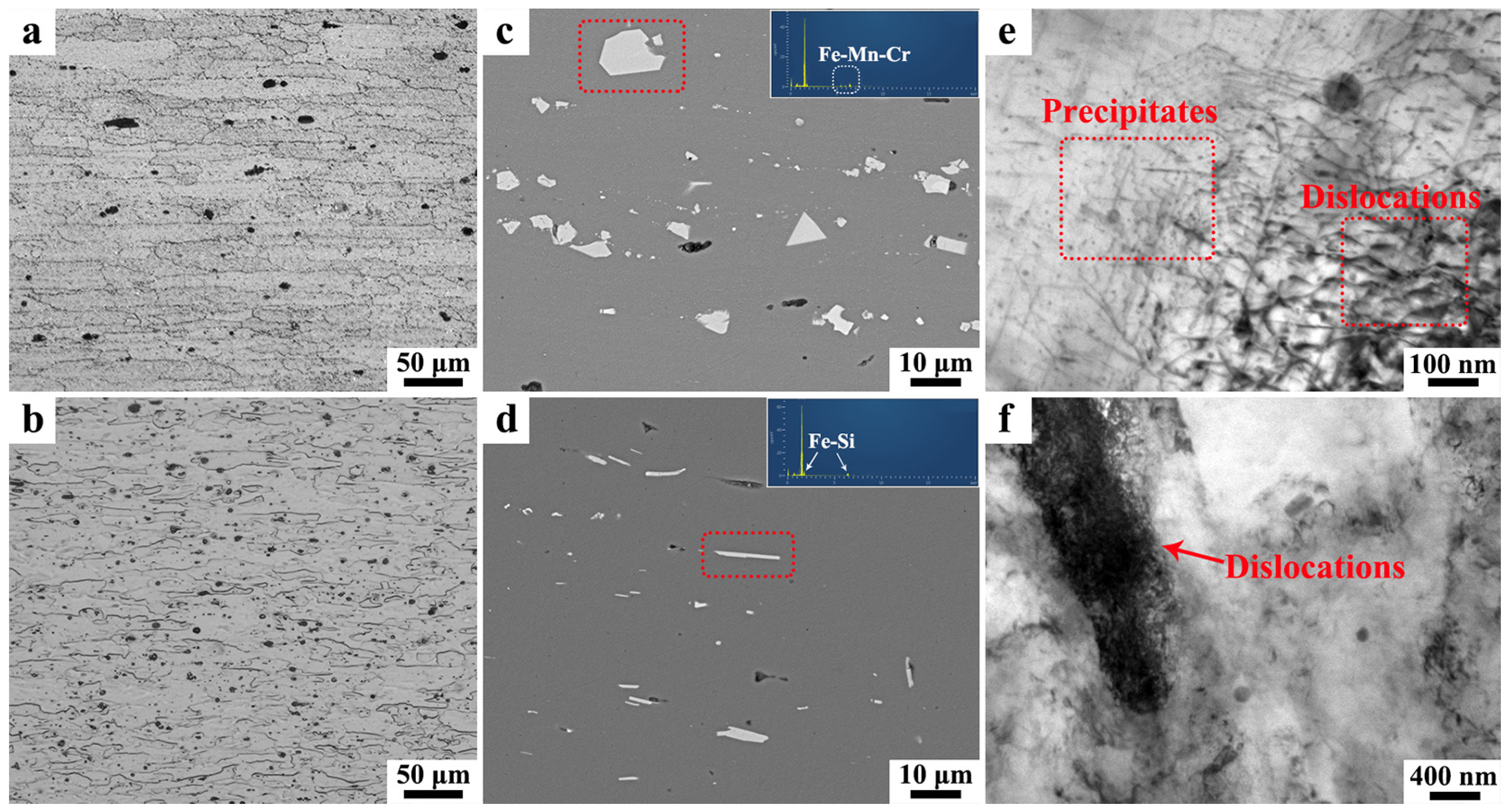
Figure 2; the grains in both Al-7075 and Al-5052 are elongated because of cold rolling (
Figure 2a,b). Al-7075 exhibits larger grains, with lengths on the order of 200–300 μm and widths of 20–30 μm, while the grains in Al-5052 are shorter in length (100–200 μm) yet comparable in width. Additionally, second-phase particles, specifically Fe-Mn-Cr-rich and Fe-Si-rich types, are observed in the Al matrix (
Figure 2c,d). A relatively high dislocation density is evident in the base metals (
Figure 2e,f). Moreover, the rolled Al-7075 alloy is in the T651 temper condition, which involves an artificial aging process; thus, some fine precipitates are detected in Al-7075, which can be identified as being in the MgZn
2 phase [
23].
The cross-sectional views of FSLW joints fabricated via different ultrasonic powers are presented in
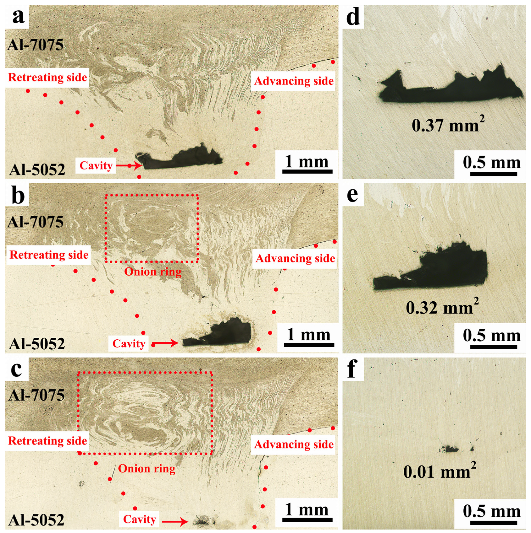
Figure 3. In the nugget zone, Al-7075 and Al-5052 intermix to form a lamellar structure on the advancing side, with the dark lamella originating from Al-7075 and the bright lamella from Al-5052. During FSLW, the materials ahead of the stir tool are first sheared into the nugget zone and then rotate around the stir tool, forming the lamellar structure and/or onion ring [
24]. If material flow is insufficient, the material cannot complete this rotation, leading to the formation of cavity defects. In the FSLW joint without ultrasonic assistance (
Figure 3a), an onion ring structure is also observed on the retreating side; however, this structure appears indistinct. Based on our previous study [
25], a distinct onion ring only forms when material rotation around the stir tool is sufficient, suggesting that material flow is inadequate under non-ultrasonic assistance conditions. As a result, a large cavity with an area of 0.37 mm
2 forms in the nugget zone. With ultrasonic assistance, stress superposition and acoustic softening significantly enhance material flowability [
26], promoting material rotation around the stir tool and thereby eliminating cavity defects. Moreover, Liu et al. [
27] found that applying ultrasonic assistance increased the flow velocity of material around the stir tool. This enhanced material transport, which promoted cavity healing. Consequently, the cavity area was reduced to 0.32 mm
2 with the application of 300 W ultrasonic power (
Figure 3b). Additionally, a distinct onion ring emerges with an increasing ultrasonic power (
Figure 3b,c), indicating that enhanced material flowability positively correlates with ultrasonic power. Although cavity defects persist in all FSLW joints, their cross-sectional area decreases progressively with higher ultrasonic power (
Figure 3d–f). The insufficient material flow consistently induces cavity formation, which can be suppressed by enhanced material flowability [
28]. As a result, the cavity area declines from 0.37 mm
2 to 0.01mm
2 when the ultrasonic power rises from 0 W to 600 W.
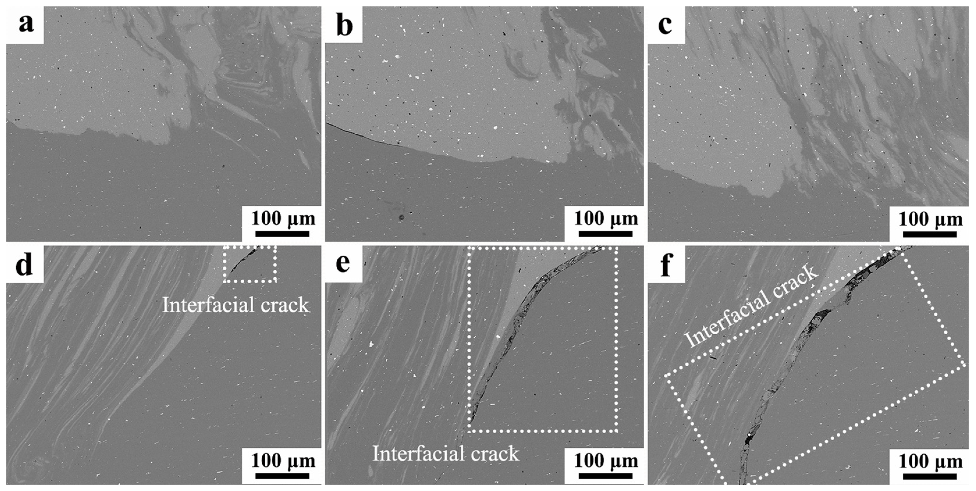
Figure 4 presents the interfacial morphologies between Al-7075 and Al-5052 on the retreating and advancing sides. Unlike OM observations, secondary-electron SEM imaging reveals brighter contrast in Al-7075 and darker contrast in Al-5052. The Al-7075/Al-5052 interface exhibits tight bonding on the retreating side (
Figure 4a–c), whereas the interfacial crack is detected on the advancing side (
Figure 4d–f). Notably, the interfacial crack propagation intensifies with an increasing ultrasonic power. Without ultrasonic assistance, the interfacial crack exhibits limited penetration into the nugget zone, extending only minimally beyond the interface (
Figure 4d). At 300 W ultrasonic power, however, the interfacial crack propagates rapidly across the nugget zone boundary (
Figure 4e). Further increasing the ultrasonic power to 600 W induces interfacial crack widening and extension to the nugget zone bottom (
Figure 3c and
Figure 4f). This interfacial crack compromises Al-7075/Al-5052 bonding integrity, potentially deteriorating the FSLW joint performance.
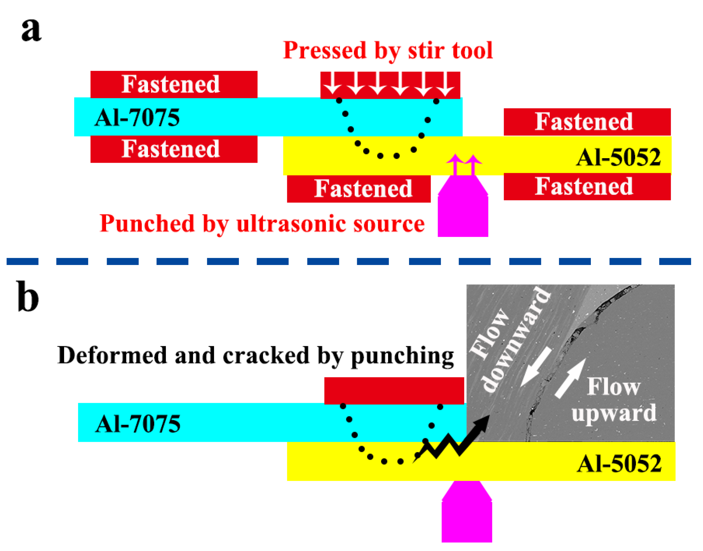
The reason for interfacial crack formation is demonstrated in
Figure 5. Both Al-7075 and Al-5052 plates remain fastened, and two kinds of forces are applied during FSLW (
Figure 5a): (1) the downward compressive force from the stir tool acting on the upper Al-7075 plate and (2) high-frequency oscillatory excitation (matching ultrasonic frequency) from the ultrasonic source punching the lower Al-5052 plate. The heat generated by FSLW softens the materials, reducing the deformation resistance of Al-7075/Al-5052. Without ultrasonic assistance, the stir tool pressure constrains the materials’ outflow, suppressing flash formation [
29]. Simultaneously, the materials beneath the stir tool flow downward, enhancing Al-7075/Al-5052 mixing in the nugget zone. When 300 W ultrasonic power is applied, the punch effect of the ultrasonic source induces upward material flow in the lower Al-5052 plate. And counter-directional material transport disrupts the flow equilibrium, initiating interfacial crack (
Figure 5b). In general, ultrasonic power can be calculated using Equation (1):
where
Q represents the ultrasonic power,
t is the welding time,
F denotes the punch force of the ultrasonic source,
A is the ultrasonic amplitude, and
f is the ultrasonic frequency. In this study, the welding time
t is determined by the rotational speed and weld speed. The amplitude
A and frequency
f are set and maintained by the ultrasonic equipment. Our experiments are conducted under constant rotational speed and weld speed of 800 rpm and 50 mm/min, respectively, while
A and
f are also held constant at 20 μm and 20 kHz. Therefore, under these conditions, it can be inferred that the ultrasonic power
Q increases proportionally with the punch force
F. Consequently, at 600 W ultrasonic power, the enhanced
F intensifies upward material flow in the lower Al-5052 plate, further propagating interfacial crack.
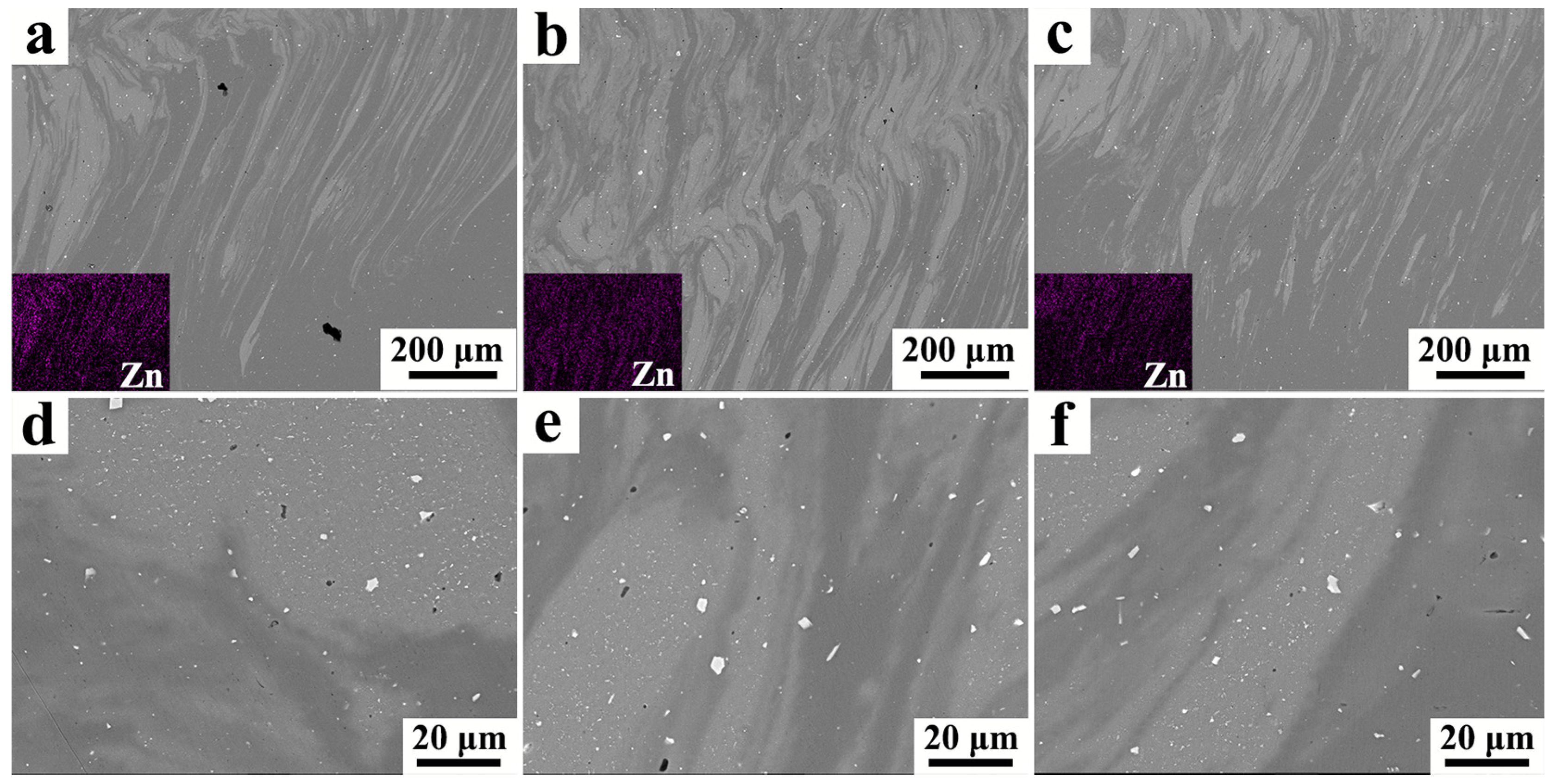
Figure 6 shows the lamellar structure and second-phase particles in the nugget zone, and two key observations emerge: (1) The atomic diffusion between Al-7075 and Al-5052 is limited, with Al-7075 exhibiting a significantly higher Zn content (
Figure 6a–c). Amancio-Filho et al. [
30] reported a similar phenomenon, attributing the lamellar structure formation to an essentially non-chemical mixture of base metals. (2) The second-phase particles are fragmented by the stir tool, while the particle size differences among all FSLW joints are negligible. This aligns with Ref. [
31], which shows that second-phase particles below a critical mean diameter could not be further fragmented. Therefore, it can be inferred that ultrasonic assistance does not effectively enhance atomic diffusion or particle fragmentation regardless of the ultrasonic power applied.
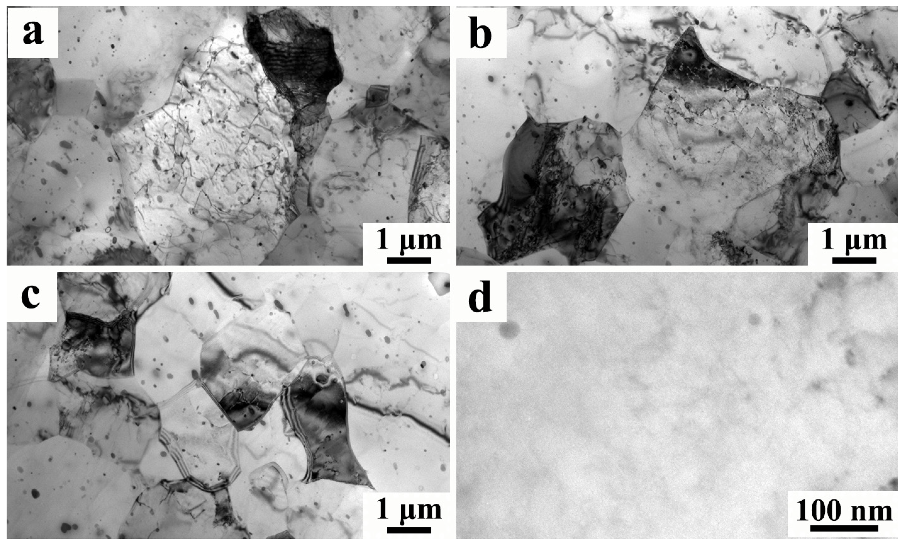
Figure 7 presents TEM images of the nugget zone, revealing the grain refinement and the reduced dislocation density. These microstructural changes are primarily attributed to dynamic recrystallization (DRX) during FSLW [
32]. Additionally, the initial fine MgZn
2 precipitates dissolve due to their relatively low dissolution temperature [
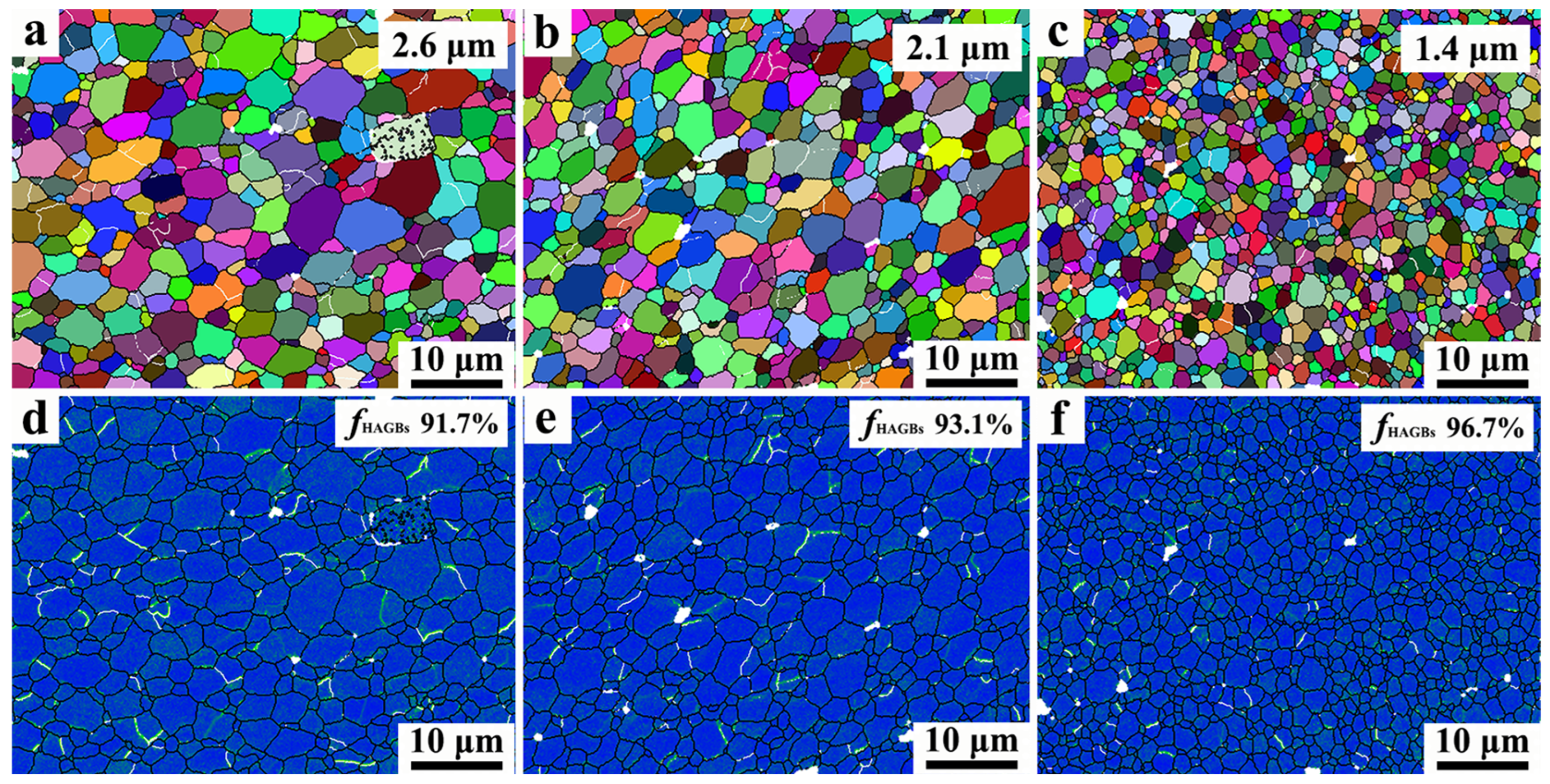
33]. Grain refinement appears to correlate with increasing ultrasonic power. To quantify this effect, EBSD is employed to analyze the grain size and the DRX behavior (
Figure 8). In the nugget zone, the initial elongated grains are replaced by the equiaxed fine grains (
Figure 8a–c). The average grain size measures 2.6 μm for the FSLW joint without ultrasonic assistance. At 300 W ultrasonic power, the average grain size further reduces to 2.1 μm (a 19% decrease). As the ultrasonic power increases to 600 W, the grain size decreases to 1.4 μm (a 46% decrease). According to Azimzadegan et al. [
34], the DRX grain size decreases with an increasing strain rate, and thus, the grain refinement caused by ultrasonic assistance primarily depends on the enhanced material flow (i.e., elevated strain rate). Furthermore, the stored energy cannot be overlooked: increased stored energy promotes the nucleation rate, thereby reducing the DRX grain size [
35]. During ultrasonic-assisted FSLW, the ultrasonic energy is transferred into the nugget zone, raising the stored energy and refining the grains. As the ultrasonic power increases to 600 W, the accumulated stored energy intensifies, resulting in the finest grain size observed among all FSLW joints.
The Kernel Average Misorientation (KAM) analysis can be used to characterize the dislocation density and the fraction of high-angle grain boundaries (HAGBs) [
36]. This analysis indicates that the dislocation density in the nugget zone is relatively low as the progression of DRX consumes dislocations [
37]. The HAGB fraction in the FSLW joint without ultrasonic assistance is 91.7%, which increases to 93.1% with the application of 300 W ultrasonic power. This increase in the HAGB fraction signifies an acceleration of DRX [
38], suggesting that DRX becomes more complete during ultrasonic-assisted FSLW. Ultrasonic energy facilitates both the dislocation climb and the grain boundaries’ mobility [
37], thereby promoting DRX. Consequently, increasing the ultrasonic power from 300 W to 600 W further elevates the level of DRX and increases the HAGB fraction to 96.7%.
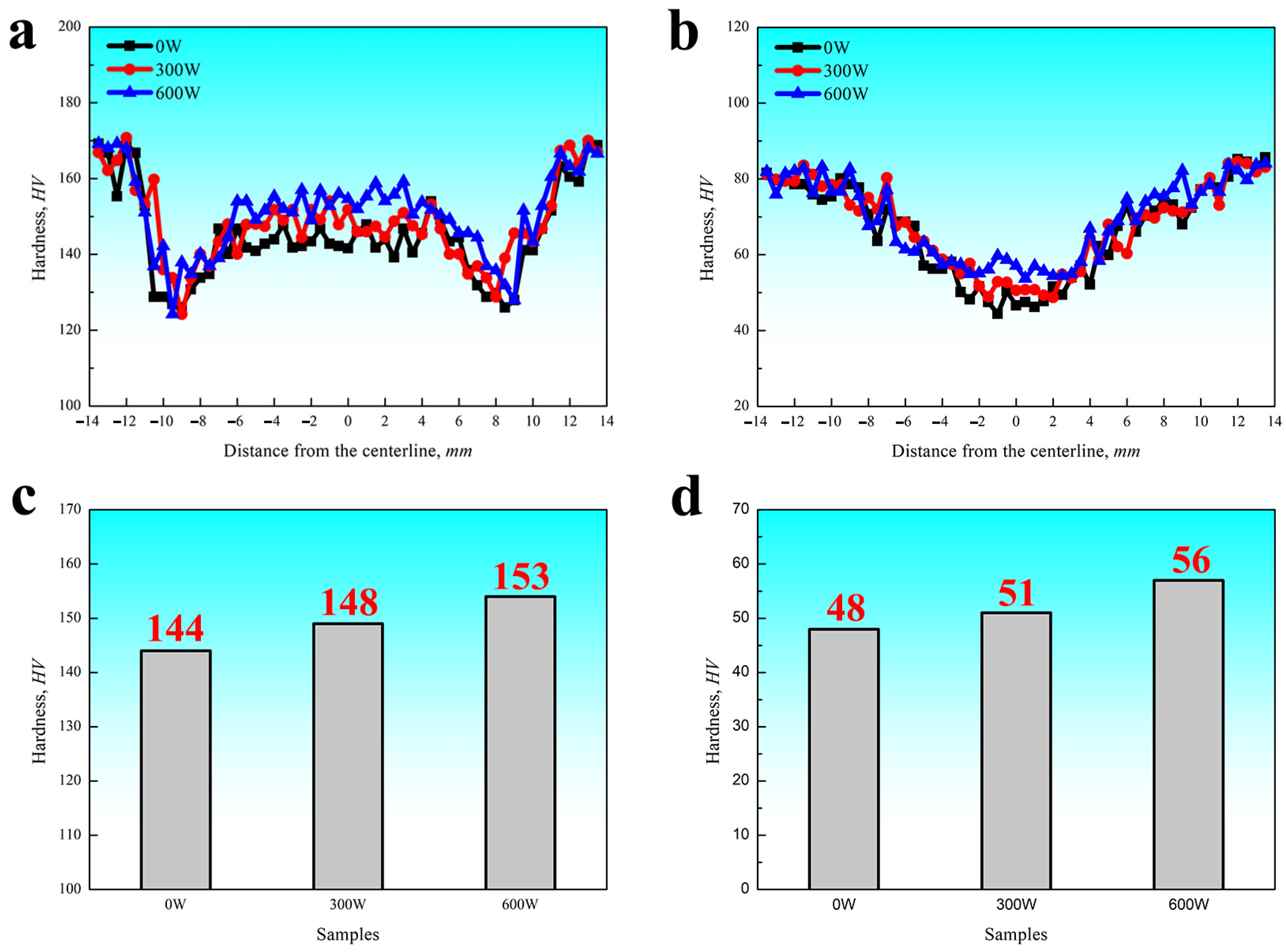
The hardness distributions of all FSLW joints are shown in
Figure 9; the hardness profile of Al-7075 shows a W shape, whereas that of Al-5052 is V-shaped. The strength of Al-7075 is primarily governed by the morphology of the MgZn
2 phase, with a fine MgZn
2 phase being beneficial for strengthening [
23]. However, the heat input of FSLW typically causes the dissolution or coarsening of the MgZn
2 phase, resulting in joint softening. In the nugget zone, the initial fine MgZn
2 phase dissolved into the Al matrix due to its low dissolution temperature, leading to a lower hardness than that of the base metal. Differently, the primary strengthening mechanism for Al-5052 is work hardening [
39]; consequently, the reduction in dislocation density in the nugget zone is responsible for softening. Compared with the FSLW joint without ultrasonic assistance, the finer grain structure in the nugget zone enhances the hardness of the ultrasonic-assisted FSLW joint, and increasing the ultrasonic power further elevates the hardness of the nugget zone. At 600 W ultrasonic power, the hardness values in the nugget zone increased from 144/48 HV (Al-7075/Al-5052) to 153/56 HV. However, the resulting enhancement from grain boundary strengthening remains insufficient to compensate for the loss of precipitation and dislocation strengthening.
Figure 10 shows the shear tensile properties of all FSLW joints. Without ultrasonic assistance, the shear tensile force of the FSLW joint is approximately 3500 N. And this value increases to 3750 N when 300 W ultrasonic power is applied. However, the shear tensile force decreases to 3300 N as the ultrasonic power is further increased to 600 W. All FSLW joints exhibit marginal differences in elongation, with the value ranging from 11% to 13%.
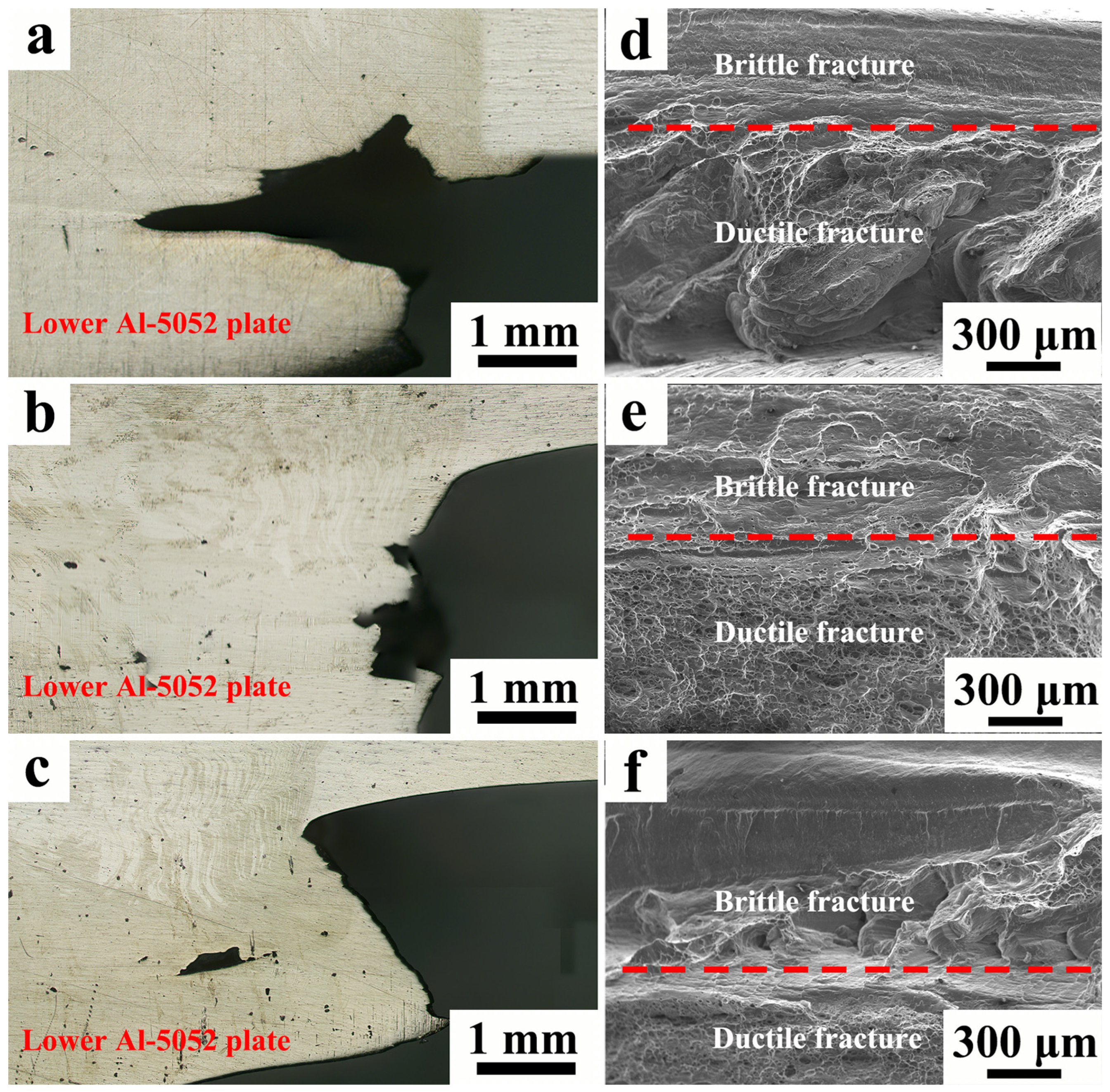
Figure 11 shows the failure morphologies of all FSLW joints. Due to the relatively low hardness of Al-5052 (
Figure 9b), all joints fracture in the lower Al-5052 plate on the advancing side. However, different fracture paths are observed: the FSLW joint without ultrasonic assistance fails at the cavity in the nugget zone (
Figure 11a), whereas the ultrasonic-assisted FSLW joints fracture along the nugget zone boundary (
Figure 11b,c). All shear tensile specimens exhibit complex failure behavior with both the ductile and brittle fracture features (
Figure 11d–f). Notably, the brittle fracture region consistently appears on top of the ductile fracture region. The detailed microstructures of fracture surfaces are shown in
Figure 12; the brittle fracture region exhibits a flat morphology (
Figure 12a–c), whereas the ductile fracture region is characterized by numerous dimples (
Figure 12d–f).
Figure 13 illustrates the fracture mechanism schematic for all FSLW joints. With a stir pin length of 5 mm and a total combined thickness of 6 mm for the Al-7075/Al-5052 stack, the pin cannot fully penetrate the lower Al-5052 plate. During the shear tensile test, the brittle fracture region is located in the weld part (i.e., the nugget zone), while the ductile fracture region appears in the non-weld part. For the FSLW joint without ultrasonic assistance, the cavity defect is large. This reduces the load-bearing area of the nugget zone, leading to fracture initiation at the cavity. In comparison, applying 300 W ultrasonic power decreases the cavity area but induces the formation of interfacial crack. The fracture path starts from the interfacial crack and terminates at the cavity; the relatively high hardness of the nugget zone nevertheless increases the shear tensile strength. However, when the ultrasonic power is further increased to 600 W, the excessive propagation of interfacial crack occurs, which degrades the bonding structure and consequently reduces the shear tensile strength.
The arrangement of the ultrasonic source in this study is similar to that used by Ji et al. [
40], and it appears that the punch effect of the ultrasonic source should not be overlooked. The configuration recently proposed by He et al. [
41] may be useful for suppressing this effect. Therefore, further research is required in order to avoid or suppress the punch effect of the ultrasonic source. Effective research directions may include adjusting the distance between the ultrasonic source and the weld centerline and reducing the ultrasonic frequency or amplitude. It should also be noted that normalizing ultrasonic power by the volume/area of power dissipation is more scientifically rigorous than using the direct ultrasonic power value. However, dynamically monitoring the volume or area of power dissipation remains highly challenging. Considerable further work is needed to achieve standardization and normalization of ultrasonic parameters.
4. Conclusions
The weld performance of dissimilar Al-7075/Al-5052 FSLW joints assisted by varying the ultrasonic power was investigated, and the following results were obtained:
(1) All FSLW joints produced in this study exhibited cavities in the nugget zone; however, increasing the ultrasonic power effectively suppressed cavity formation. This was due to the enhanced material flow from the ultrasonic-induced acoustoplastic effect, which promoted material rotation around the stir tool and delayed cavity formation. Further increasing the ultrasonic power improved material flowability even more, leading to a reduction in cavity area. Without ultrasonic assistance, the cavity area was 0.37 mm2, and this decreased to 0.32 mm2 and 0.01 mm2 with ultrasonic power at 300 W and 600 W, respectively. Furthermore, mixing between Al-7075 and Al-5052 intensified as the ultrasonic power was increased, and a distinct onion ring microstructure formed in the nugget zone with 600 W ultrasonic power. Nevertheless, the excessive ultrasonic power level of 600 W amplified the ultrasonic punch effect, inducing interfacial crack formation between Al-7075 and Al-5052 on the advancing side.
(2) Both the second-phase particles and grains in the nugget zone underwent refinement; moreover, the average grain size decreased from 2.6 μm to 1.4 μm as the ultrasonic power increased. Additionally, the dynamic recrystallization of the nugget zone became more complete, the fraction of high-angle grain boundaries was 91.7% for the non-ultrasonic-assisted FSLW joint, and it increased to 93.1% and 96.7% with the application of 300 W and 600 W ultrasonic power, respectively.
(3) Without ultrasonic assistance, the nugget zone of the FSLW joint softened compared to the base metals, exhibiting an average hardness of 144/48 HV. This softening of the nugget zone was primarily attributed to the loss of precipitation and dislocation strengthening. By contrast, the application of 300 W ultrasonic power elevated the hardness of the nugget zone to 148/51 HV due to grain refinement. Increasing the ultrasonic power to 600 W further enhanced the nugget zone, and the hardness value could reach 153/56 HV.
(4) The failure behavior of the FSLW joint was governed by both the cavity and the interfacial crack. For the non-ultrasonic-assisted FSLW joints, the large cavity area led to fracture initiation at the cavity, while for the 600 W-ultrasonic-assisted FSLW joint, fracture occurred along the interfacial crack. The application of 300 W ultrasonic power could effectively suppress both the cavity and the interfacial crack, resulting in the highest shear tensile strength (3750 N) observed in this study.
Ultrasonic-assisted FSLW shows great promise in refining microstructures, reducing weld defects, and improving the performance of dissimilar aluminum joints. With potential applications in manufacturing industries such as automotive and aerospace, this technique also contributes to broadening the process window. Compared to ultrasonic-assisted FSLW of other material pairs, such as Al/Mg, Al/Fe, and Al/Ti, the primary challenge in dissimilar Al-to-Al welding is mitigating weld defects (the cavity and the interfacial crack) rather than preventing the formation of intermetallic compounds (IMCs). Nevertheless, understanding the effect of ultrasonic assistance on the formation of IMCs is also crucial and requires urgent investigation.
