Article

Influence of Different Heat Treatments on Microstructure Evolution and High-Temperature Tensile Properties of LPBF-Fabricated H13 Hot Work Steel

Department of Mathematics Computer Science and Engineering, Université du Québec à Rimouski, Rimouski, QC G5L 3A1, Canada
*
Author to whom correspondence should be addressed.
Metals 2025, 15(9), 1003; https://doi.org/10.3390/met15091003
Submission received: 7 May 2025 / Revised: 28 August 2025 / Accepted: 29 August 2025 / Published: 9 September 2025
(This article belongs to the Special Issue Laser Additive Manufacturing of Metallic Alloys)

Abstract

This study investigates the effect of tensile test temperatures, ranging from 300 °C to 600 °C, on the microstructure, mechanical properties, and fracture behavior of AISI H13 11 tool steel manufactured by laser powder bed fusion (LPBF) under three material conditions: As-Built (AB), Direct Double-Tempered (DTT), and 13 Quenched and Double-Tempered (QTT). Optical and SEM observations show that quenching before tempering leads to a more homogeneous microstructure. Full austenitization during quenching eliminates the laser track patterns and cellular structures characteristic of the AB and DTT conditions, resulting in a microstructure like that of conventionally processed material. Tensile test results reveal that, while all material conditions (AB, DTT, and QTT) perform similarly at lower temperatures (up to 300 °C), significant differences emerge at elevated temperatures. At 300 °C, AB, DTT, and QTT maintain 87.5%, 85.8%, and 83.1% of their room-temperature yield strength, respectively. However, beyond this point, the DTT condition clearly outperforms the others. QTT shows a sharp decline above 300 °C, retaining only ~24% of its yield strength, whereas AB and DTT maintain approximately 80%. The superior performance of DTT becomes more evident at higher temperatures: it retains 25% and 20% of its yield strength at 500 °C and 600 °C, respectively, higher than both AB and QTT.

1. Introduction

AISI H13 is a widely used hot-work tool steel valued for its thermal stability, mechanical strength, and resistance to wear and thermal fatigue, making it ideal for applications such as die casting and molding [1,2]. These properties stem from its refined microstructure and alloying elements, including Cr, Mo, Si, and V, which contribute to oxidation resistance and the formation of stable carbides like Mo2C and VC that hinder grain growth [3,4]. Heat treatment—typically involving austenitizing, quenching, and tempering—yields a tempered martensitic structure reinforced by M7C3 and M23C6 carbides, enhancing high-temperature strength and creep resistance [5,6]. However, H13’s structural integrity declines above 850 °C due to carbide dissolution and grain boundary sliding, leading to thermal softening and superplastic behavior [7].
When fabricated via laser powder bed fusion (LPBF), H13 faces additional challenges not present in conventional manufacturing. Rapid solidification induces defects such as residual stresses, lack of fusion, keyhole porosities, and retained austenite, as well as elemental segregation and surface roughness [8,9,10]. Many of these can be mitigated through optimized parameters—preheating above 200 °C to reduce thermal gradients [11] and controlled energy density and Marangoni flow to minimize porosity and segregation [12,13]. Carbon evaporation also introduces ferrite formation and microstructural inconsistency. In the As-Built (AB) state, LPBF-H13 may contain up to 19% retained austenite, which heat treatments (austenitizing at 1020 °C, oil quenching, and double tempering) can reduce to under 5%, yielding a more uniform microstructure [14,15]. Further optimization of print strategies and preheating has enhanced mechanical stability [16]. Nonetheless, the thermal–mechanical performance of LPBF-H13, particularly in high-temperature industrial applications, remains insufficiently understood and necessitates detailed investigation.
Research on the high-temperature behavior of AM-processed metals remains limited and typically material-specific. Previous studies have focused on stainless steels [17,18], ultrahigh-strength steels [19,20], 35CrMo [21], and martensitic alloys [22], noting trends such as reduced strength and improved ductility. Investigations on H13 tool steel are scarce and largely center on chemical modifications to enhance thermal stability. Ding et al. [23] reported improved high-temperature performance by increasing Mo and W while reducing Cr, leading to finer grains and stable M6C carbides. In a separate study, increasing carbon content in spray-formed H13 enhanced strength and thermal stability via carbide precipitation, although at the expense of ductility [24]. Tanvir et al. [25] analyzed WAAM-H13 and linked high-temperature microstructural evolution to mechanical properties, noting a drop in yield strength from 1145 MPa to 804 MPa between 23 °C and 600 °C and reduced ductility relative to conventional H13. These findings highlight the need for further evaluation of AM-H13’s behavior under elevated thermal and mechanical loads.
To contextualize the thermal behavior of H13, previously published Differential Scanning Calorimetry (DSC) analyses have identified key phase transformations that influence its mechanical performance at elevated temperatures. These include the Curie point (~750 °C), the onset of austenitization between 850 and 900 °C, and the dissolution of carbides such as M6C and MC in the range of 1000–1100 °C [26]. In industrial applications, where service temperatures typically remain below 700 °C, the most relevant transformation is the precipitation of V-rich (MC) and Cr-rich (M3C) carbides. These carbides significantly enhance high-temperature strength, wear resistance, and thermal stability—essential for components exposed to cyclic thermal and mechanical loading.
This study builds upon the previous research conducted by the authors, where processing parameters have been optimized for LPBF-processed H13 [16,27,28]. The primary objective of this research was to evaluate the high-temperature tensile behavior of LPBF-H13 in three different configurations: the As-Built (AB) condition, the Direct Double-Tempered condition (DTT), and the Quench + Double-Tempered condition (QTT). This study also aims to enrich the literature, as the findings will provide additional data on evaluating how each configuration performs under high-temperature conditions, to what extent they can be used to manufacture conformal cooling channels in hot forging dies and injection molds, offering a solution for industries seeking enhanced material properties and performance in high-stress environments while simultaneously cutting costs.

2. Materials and Methods

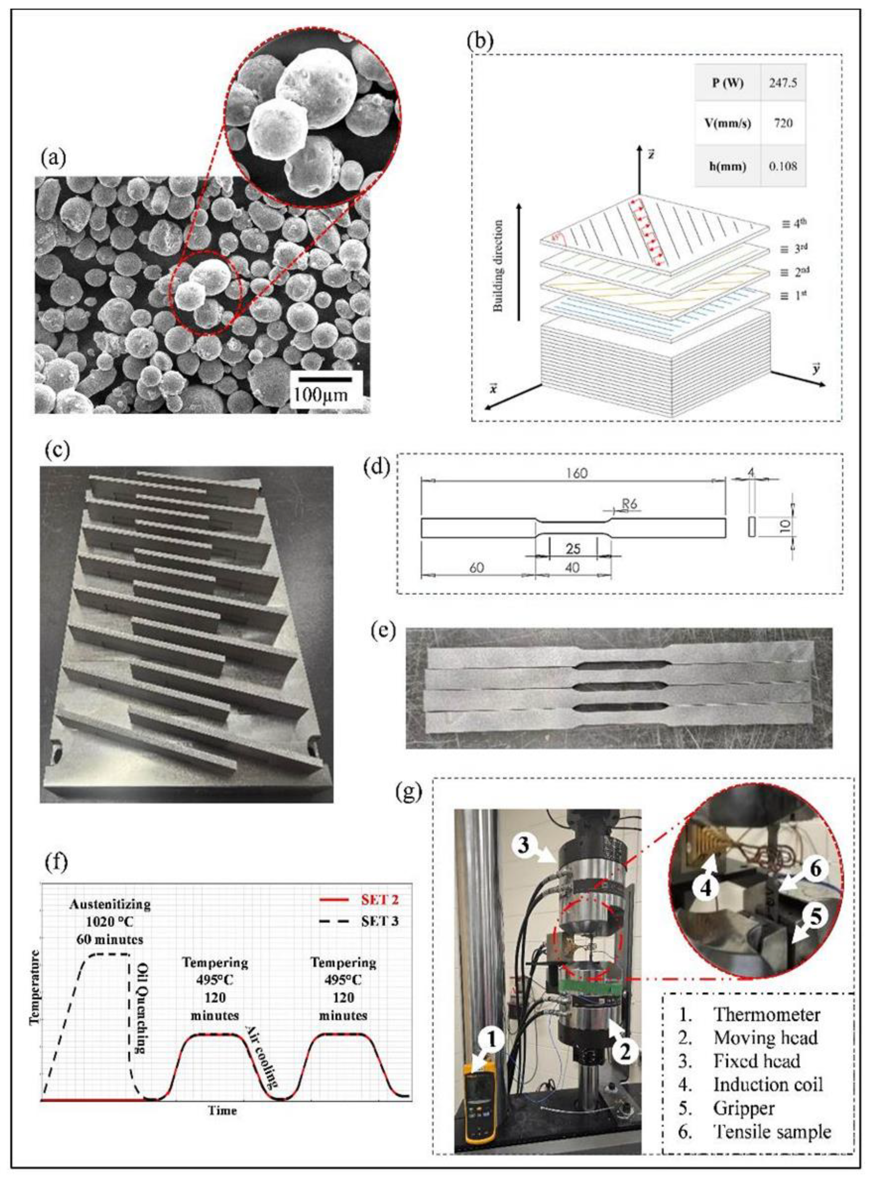
Figure 2 summarizes the materials and methods. The test specimens were additively manufactured LPBF with the EOS-M290 machine. The raw H13 powder employed was provided by BBP company (Buffalo Precision Products Inc., Buffalo, NY, USA). The gas-atomized spherical powder (Figure 2a) was composed of C: 0.3–0.5%, Cr: 5.0–6.0%, Mn: 0–0.6%, Mo: 1.0–2.0%, Si: 0.5–1.0%, V: 0.5–2.0%, and others: 0–0.05% and Fe: Bal. To inhibit oxidation, the LPBF-processed samples were built within a nitrogen (N2) atmosphere.
One set of the processing parameters was used, obtained through optimization from the author’s previous work. The strategy of the optimization is given in Figure 1. This figure shows the summary of the previous research on optimization of the process parameters and the heat treatment that could be found in the references [16,27,28].
The configured parameters incorporated laser power P (247.5 W); scanning speed V (720 mm/s), and hatch spacing h (0.108 mm). The printing strategy comprised a bidirectional scanning with a 45° rotation between consecutive layers (Figure 2b). Two measurements were conducted of dimensions of the samples manufactured, 180 mm × 16 mm × 4 mm and 10 mm× 10 mm× 15 mm, respectively, for tensile test and microstructural/microhardness observations. In total, there were 27 samples for tensile test and 9 samples for the microstructural/microhardness observation. The sample after printing for the tensile test is shown in Figure 2c. After printing, the samples were separated from the building plate and then machined in compliance with ASTM standards [29] for sub-sized samples (Figure 2d,e). Then, samples were divided into three groups, each subjected to a distinct heat treatment. The first group was retained in the As-Built (AB) condition with no additional processing. The second group underwent a Direct Double Tempering (DTT) at 495 °C for 120 min in each cycle. The third group was austenitized at 1020 °C for 60 min, followed by oil quenching, and then subjected to double tempering at 495 °C for 120 min per cycle, with air cooling between tempering steps. These heat treatment protocols are illustrated schematically in Figure 2f.
After heat treatment, all specimens were sandblasted to improve surface roughness for better gripping during tensile testing and to ensure consistency across repeated tests. High-temperature tensile tests were performed using an induction heating system, detailed in Figure 2g. The setup consisted of a coil placed around the specimen, mounted on a fixture aligned with the MTS tensile testing machine. The specimen temperature was monitored using a thermocouple and a thermometer. Testing was initiated only after the temperature stabilized and was uniform across the entire gauge section. The tensile specimens were 160 mm in length and 10 mm in gauge height, allowing proper placement within the induction coil and testing machine. A thickness of 4 mm was chosen to promote rapid heat transfer and ensure uniform temperature distribution. Tensile tests were conducted at room temperature (RT) and at elevated temperatures of 300 °C, 400 °C, 500 °C, and 600 °C, using a constant strain rate of 0.001 s−1, with three repetitions for each of them. All three material conditions—As-Built (AB), Direct Double-Tempered (DTT), and Quenched and Double-Tempered (QTT)—were tested under identical conditions.
For microstructural observations, 10 mm× 10 mm× 15 mm samples were sectioned from the mid-plane in two orthogonal directions to allow examination in all three principal orientations. The specimens were mounted in epoxy resin and chemically etched using Vilella’s reagent for 15 s to reveal the microstructural features. Optical microscopy was used for initial examination, while scanning electron microscopy (SEM) was performed using an SNE−4500M system. SEM was also employed for fractographic analysis of the fracture surfaces after tensile testing.
Figure 2. Experimental methods, protocols and equipment to fabricate, prepared and tested high-temperature tensile samples: (a) SEM image of the powder, (b) printing strategy, (c) as-printed samples, (d) sample dimensions for the tensile test, (e) cut samples according to the specified size, (f) heat-treatment procedure, and (g) high-temperature tensile test setup.
Metals 15 01003 g002

3. Results and Discussion

3.1. Microstructure

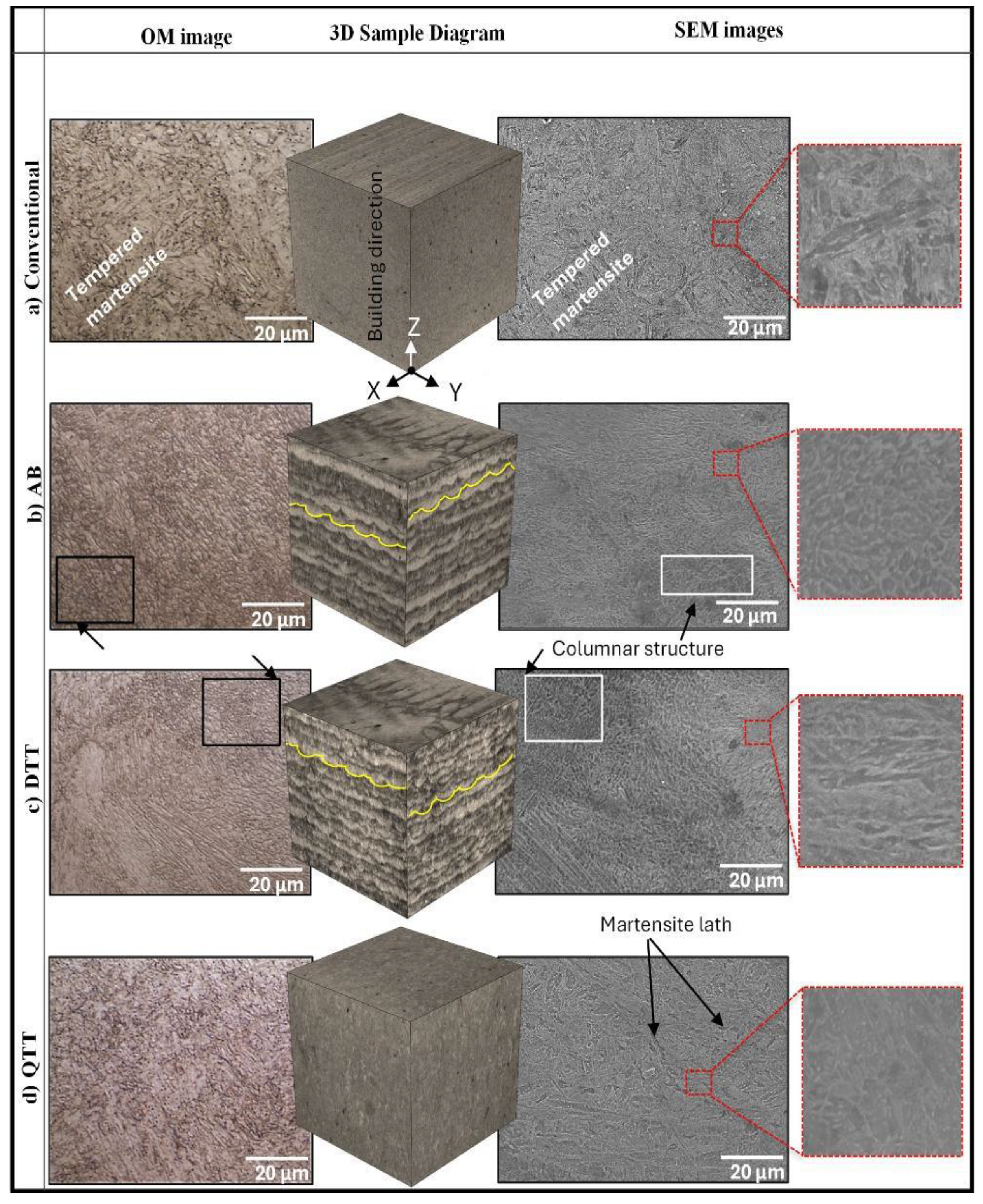
The results of the microscopic observations are presented in Figure 3. The figure shows optical microscopy (OM) and SEM images describing different microstructure configurations of the material: conventional (Figure 3a), AB (Figure 3b), DTT (Figure 3c), and QTT (Figure 3d), with a 3D diagram showing planes of interest. The conventional heat-treated material, seen in Figure 3a (quench + double temper), is viewed as a reference. As for the AB material, it shows a highly anisotropic microstructure due to the layer-wise solidification. The (XZ) cross-section, corresponding to the building direction, reveals elongated columnar grains and melt pool traces extending along the building direction. Moreover, in the building plane (XY), overlapping melt pool boundaries form semi-circular patterns. The perceived heterogeneity is a result of the thermal gradient and printing strategy of the process. Due to the high cooling rates, the alloying elements, namely, chromium, vanadium, and molybdenum, segregate in a cellular pattern within the martensite matrix. The resulting structure is composed of a cellular arrangement composed of lath martensite and a varying fraction of retained austenite, as seen in the SEM image. The DTT configuration in Figure 3c shows multiple characteristic elements of the AB microstructure that have been retained. The melt pool boundaries and layer bands can still be observed after tempering. However, the structural homogeneity is improved in comparison to the AB configuration. The prior martensitic matrix is transformed into tempered martensite, and the retained austenite is converted into a combination of ferrite and carbides. The tempered martensite laths maintain their fine structure with the same arrangement. A discernible difference seen in the SEM image lies in the fine carbides dispersed throughout the microstructure, precipitating along the original solidification cell boundaries [30,31]. As for the QTT configuration (Figure 3d), the microstructure changes significantly as the most unique features of the AB material, namely, the melt pool and layer features, are largely erased. Austenitizing at 1020 °C homogenizes the microstructure by forming new austenite grains and mitigating alloying elements segregation [32,33] Therefore, cross-sections taken along all directions exhibit the same microstructure. In fact, at low magnification, the OM images show a uniform tampered martensitic structure, implying that the cellular microstructure and the banding seen in the AB condition have been dissolved due to diffusion during the heat treatment. At high magnification, a matrix of tempered martensite with fine and dispersed Cr-rich and M7C3 carbides, precipitating during tempering, is visible through SEM images. Some ferrite grains can also be seen, which formed due to the lack of carbon content as a fraction evaporated during the printing process [34,35].
All three configurations exhibit different microstructural traits, which make them susceptible to thermal softening to varying degrees. Notably, the AB H13 can display a phenomenon of secondary hardening upon initial heating: the retained austenite present can transform into fresh martensite or decompose into fine carbides and ferrite, which increases hardness instead of decreasing it. However, beyond the secondary hardening peak, continued high-temperature exposure will soften the AB microstructure significantly, meaning that the martensite will over-temper and coarsen, and any newly formed carbides can start coarsening as well. Also, the lack of any pre-formed stable carbides in AB means that, once the retained austenite is exhausted and the dislocation structure recovers, rapid softening can occur. As for QTT, its microstructure is mainly composed of tempered martensite and alloy carbides that were formed during tempering. These carbides effectively pin the martensitic lath boundaries and impede dislocation motion at elevated temperatures, thus resisting softening. However, the microstructure is still susceptible to over-tempering, making it significantly vulnerable to softening at higher temperatures. In fact, once QTT is heated above its tempering range, the tempered martensite will coarsen further, and carbides may coalesce, causing a drop in thermal stability. The DTT heat treatment involves tempering the LPBF part in the AB state twice, for 2 h at 495 °C per treatment without prior quenching. This heat treatment protocol preserves the original solidification microstructure while relieving stress and precipitating carbides. Therefore, based on initial microstructural and metallurgy-based observations, DTT is likely to be the most resistant to thermal softening because it combines a high density of fine precipitates with the inherent fine scale of the AB martensite. Some studies have reported that direct tempering leads to a lower softening rate at high temperatures when compared to the conventional quench and temper route. The finely dispersed carbides in the DTT samples effectively hinder dislocation movement and lath boundary migration even at elevated temperatures, thereby slowing down the softening process. In fact, Yuan et al. [32] found that DTT samples of LPBF H13 have thermally softened to a lesser extent than QTT samples, when exposed to high temperatures. As such, it is possible to link the improved softening resistance to the dense network of nanoscale carbides along the cell boundaries and within the martensite, which provides a strong pinning effect, further hindering dislocation movement.

3.2. Fractography

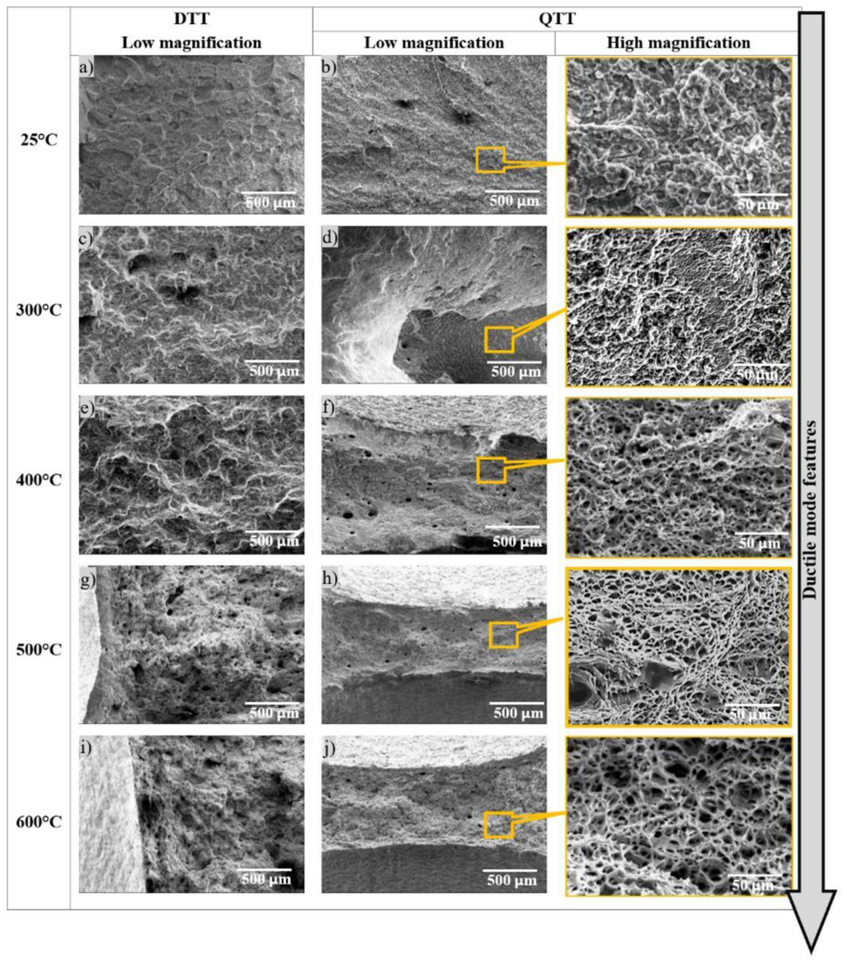
Figure 4 illustrates the temperature-dependent transition in fracture modes from room temperature to 600 °C. Low-magnification images facilitate comparison between DTT and QTT configurations, while a high-magnification QTT image highlights detailed fracture features.
At 25 °C, the DTT specimen (Figure 4a) exhibits a mixed brittle–ductile fracture mode. This behavior is characteristic of the martensitic microstructure, where brittle cleavage often occurs along prior melt pool boundaries or segregation lines, interspersed with ductile micro-void coalescence regions [30,31,33]. The image also reveals flat cleavage facets alongside rough, fibrous areas, reflecting this combination of fracture mechanisms. The presence of small dimples—commonly associated with ductile fracture—can be inferred from the rough morphology, while river patterns on the flat facets confirm the contribution of brittle fracture. The observed mixed-mode fracture is attributed to the fine cellular microstructure and the presence of LPBF-induced defects that act as crack initiation sites.
At 25 °C, the QTT specimen (Figure 4b) displays a predominantly ductile fracture morphology. This is a result of the tempered martensitic microstructure, in which carbon precipitates as fine carbides and retained austenite is transformed during tempering, enhancing toughness [31]. The low-magnification SEM image reveals a fibrous, irregular fracture surface with no large cleavage facets. A high-magnification image shows numerous equiaxed dimples of varying sizes, many of which have nucleated at carbides. These carbides serve as effective micro-void nucleation sites, increasing dimple density and enabling greater energy absorption during fracture. This fracture behavior aligns well with the findings of Lei et al. [36], who reported similar ductile morphology in heat-treated H13 and mixed-mode fracture in AB specimens.
At 300 °C, the fracture morphology remains similar to that observed at room temperature, indicating a transitional stage with no significant change in fracture mode (Figure 4c,d). The DTT specimens still exhibit a mixed brittle–ductile character, with both flat cleavage facets and fibrous regions present. Similarly, the QTT specimens maintain a predominantly ductile appearance with visible dimples; however, there is no substantial increase in dimple size or necking relative to 25 °C. These observations suggest that, at 300 °C, the material has not yet undergone a notable shift in deformation mechanism, and the fracture behavior remains dominated by mechanisms active at lower temperatures.
As the test temperature rises from 300 °C to 600 °C, the fracture mode shifts towards fully ductile for all materials with varying degrees, and distinctions in mechanisms can be seen.
As the test temperature increases to 400 °C, the fracture behavior transitions significantly toward ductile failure for both AB and QTT conditions, with QTT showing more pronounced ductile features. At the AB condition (Figure 4c), fractures become less brittle, as they show far fewer cleavage facets than at 25 °C; instead, the fracture surface is partially affected by void coalescence with larger, more irregular dimples. In Figure 4d, QTT fracture surfaces at 400 °C are entirely ductile. Multiple dimples have either grown or fused, as the material can undergo greater plastic deformation allowing voids to grow before the final fracture.
At 500 °C and above, all fracture surfaces exhibit features characteristic of classic ductile overload failure, with increased dimple size and extensive plastic deformation (Figure 4g–j). The QTT specimens display pronounced necking and a highly fibrous morphology, clearly visible in Figure 4h,j. The corresponding high-magnification images show large, equiaxed dimples formed by the growth and coalescence of micro-voids, reflecting the material’s increased capacity for plastic deformation at elevated temperatures. The DTT specimens also show ductile fracture characteristics (Figure 4g,i), though with less pronounced necking compared to QTT.
The primary distinction between QTT and DTT at high temperatures lies in the size, uniformity, and distribution of dimples. In QTT, the presence of uniformly distributed fine carbides—resulting from the tempering treatment—promotes homogeneous micro-void nucleation, leading to a more uniform dimple field. In contrast, QTT conditions typically exhibit less uniformity in dimple morphology due to the absence of such precipitates and the presence of retained austenite and solid-solution carbon.
These observations align with established high-temperature deformation mechanisms. Wang et al. [37] reported that, in a similar hot-work die steel (4Cr5MoSiV1Ti), fracture mode transitioned from brittle to ductile with rising temperatures, accompanied by a shift from dislocation slip to grain boundary sliding—consistent with the thermally activated deformation processes observed in LPBF-processed H13.
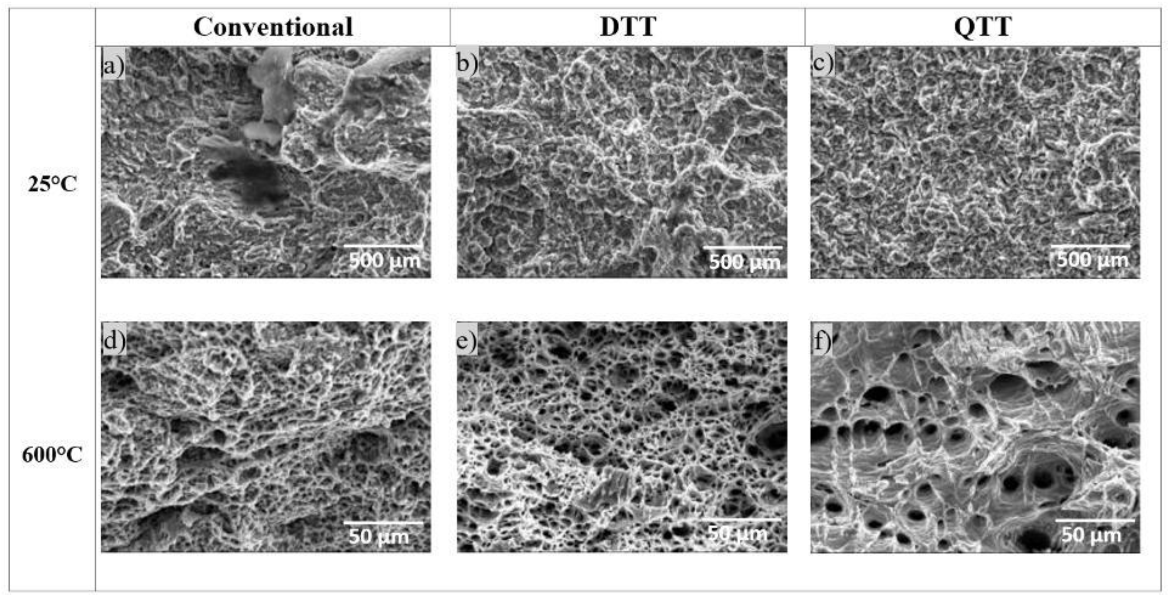
Figure 5 presents a comparative fractographic analysis of ductile fracture features for conventional, DTT, and QTT H13 specimens at 25 °C and 600 °C. At room temperature (Figure 5a–c), both the conventional and DTT specimens exhibit similar ductile morphologies, characterized by fine and uniformly distributed dimples, indicative of stable micro-void coalescence. In contrast, the QTT sample (Figure 5c) also displays a fully ductile fracture surface but with slightly coarser dimples, reflecting its increased toughness following tempering. At 600 °C (Figure 5d–f), all configurations display classic ductile overload fracture, yet morphological differences remain. The DTT specimen (Figure 5e) continues to closely resemble the conventional sample (Figure 5d), both showing homogeneous dimple patterns and refined void structures. The QTT specimen (Figure 5f), while also ductile, reveals significantly larger and deeper dimples, suggesting enhanced plastic deformation and micro-void growth, but with reduced uniformity compared to the conventional and DTT specimens. These observations indicate that the DTT condition best reproduces the fracture morphology of conventionally heat-treated H13 across the tested temperatures, while QTT enhances ductility at the expense of uniformity.

3.3. Mechanical Properties

Table 1 summarizes the mechanical properties of the AB and heat-treated LPBF-processed H13 samples at room temperature, then between 300 °C and 600 °C. The tracked mechanical properties were Yield Strength (YS), Ultimate Tensile Strength (UTS), and Elongation at fracture (El fracture).
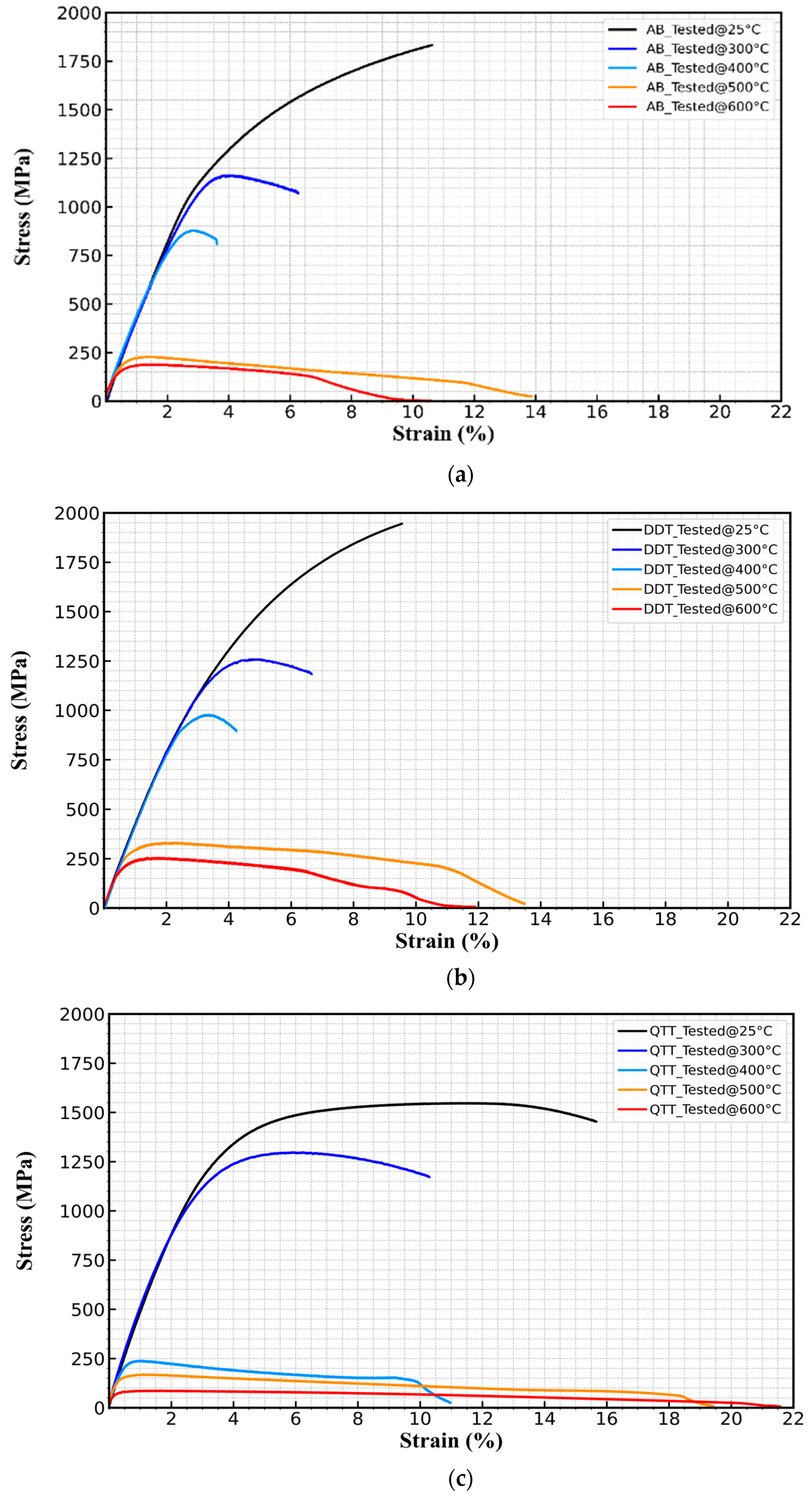
The stress–strain curves for AB, DTT, and QTT, shown in Figure 6a–c, respectively, exhibit trends that are significantly affected by the temperature. First as displayed in Figure 6a, at 25 °C, the engineering curve for the AB material exhibits a mixed ductile–brittle behavior expressed by a high yield point and a narrow strain hardening region. In the AB state, H13 exhibits high dislocation density and a very fine cellular structure, which grants it high initial strength. However, due to the lack of tempering, it also has internal stresses and some brittle martensite. By 300 °C, the yield point is lower, and the material flows more smoothly, at a nearly constant stress or with a slight gradual rise to UTS. Strain hardening, while still present, is reduced. Beyond 300 °C, the strain-hardening tends to decrease with temperature, and the curves become flatter. At these temperatures, the material exhibits a smooth and continuous plastic deformation, and thermal softening causes the flow stress to decrease with further strain, producing a peak in the curve followed by a drop before fracture. At 600 °C, H13’s stress–strain curve shows a very low yield strength, and, after yielding, the material might exhibit a short hardening region followed by either a plateau or mild flow softening as necking begins. As a result, the fracture strain at 600 °C is much larger, the material is fully ductile, and necking is diffuse. This corresponds to the observed fracture mode transition from predominantly brittle at RT to fully ductile at 600 °C. The AB material maintains a high yield point at 400 °C. The trend in elongation corresponds to the configuration’s critical temperature. The AB material’s ductility decreases up to a temperature in the range [400; 500] then increases at 500 °C.
As for the DDT configuration, seen in Figure 6b, it tends to be the strongest overall because it combines the fine AB structure with tempering, effectively obtaining the benefit of both. Double tempering closes the gap in strength, as it induces secondary hardening. Moreover, DTT can retain strength nearly equal to AB because it preserves the fine microstructure present in AB microstructure and further adds tempering-induced precipitates. At 25 °C, DTT’s curve shows high strength with better plasticity than AB. At 300 °C, the material flows more smoothly due to dislocation recovery. Beyond 300 °C, similar thermal softening trends are observed, with reduced strain hardening and smoother plastic deformation. At 600 °C, the DTT material exhibits a very ductile curve. The DTT material maintains a high yield point at 400 °C. By 500 °C, it becomes fully ductile, showing extensive plastic deformation before failure. The trend in elongation corresponds to the configuration’s critical temperature. DTT material’s ductility decreases up to a temperature in the range [400; 500] then increases at 500 °C.
Conversely, Figure 6c reveals that QTT-processed samples at room temperature show a more pronounced plastic region after the yield point indicative of ductile behavior, as tempered martensite accumulates more plastic strain with continuous yielding, before necking. QTT and DTT both temper the martensite, which slightly reduces the peak strength as tempered martensite is softer than its untampered counterpart, due to carbon redistribution. QTT has a small strength drop vs. AB at room temperature as re-austenitizing transforms the fine cell structure, and its strengthening effect is lost. By 300 °C, the yield point is lower, and the material flows more smoothly, due to several dislocations dynamically recovering at this temperature, especially in tempered conditions. Beyond 300 °C, thermal softening dominates. The QTT-treated material’s shift is between 300 and 400 °C, resulting from limited ductility transitioning to significantly improved ductility. By 500 °C, QTT becomes fully ductile, showing extensive plastic deformation before failure. The trend in elongation corresponds to the configuration’s critical temperature. As stated, QTT’s critical temperature lies between 300 and 400 °C, and so does the shift in ductility.
Based on the engineering curve analysis, it can be concluded that DTT can retain strength nearly equal to AB because it preserves the fine microstructure present in AB microstructure and further adds tempering-induced precipitates. Moreover, QTT has a small strength drop vs. AB at room temperature as re-austenitizing transforms the fine cell structure, and its strengthening effect is lost. DTT tends to be the strongest overall because it combines the fine AB structure with tempering, effectively obtaining the benefit of both. This was evidenced by Yuan et al. [32] who reported that direct tempering yielded lower thermal softening and good strength due to more dispersed carbides.
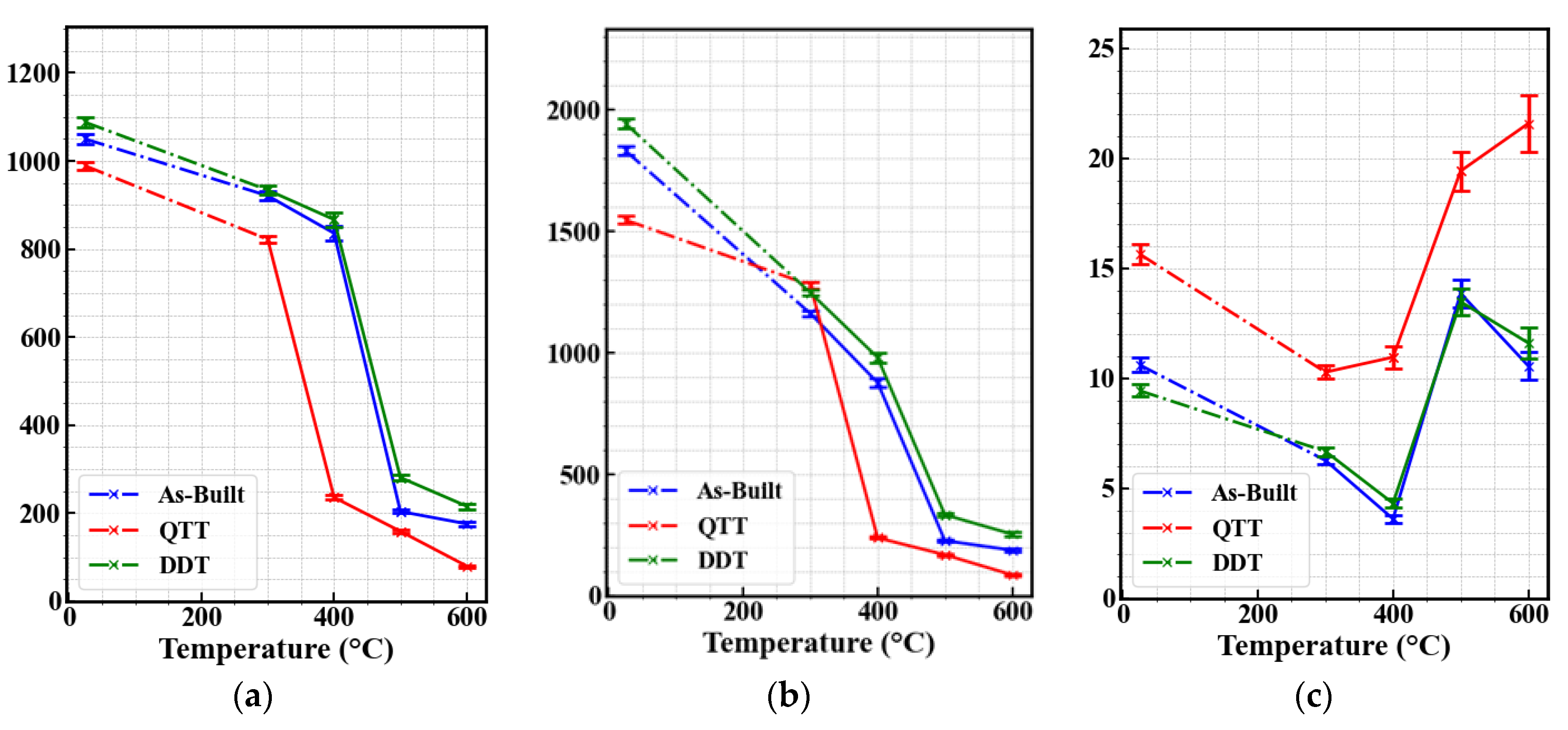
Figure 7 tracks the evolution of YS, UTS, and El fracture (Figure 7a–c, respectively) of the different material configurations in the tested temperature range.
For the AB material, depicted in Figure 7a, YS decreases slightly by 11.6% at 300 °C (from 1071 MPa at 25 °C to 947 MPa) and remains relatively stable at 400 °C, decreasing by only 21.9% compared to room temperature. However, strength drastically declines at higher temperatures, by 81% at 500 °C and a further 84% at 600 °C, respectively. DTT follows the same trend but retains higher mechanical strength than the AB material, maintaining a YS of 867 MPa at 400 °C, about 80% of its value at room temperature. In contrast, the QTT configuration, despite having comparable initial room-temperature strength, is more prone to strength decay as the temperature increases. Yield strength at 300 °C decreases by 16.9%, followed by a severe drop of 76.1% at 400 °C, indicating less thermal stability compared to AB and DTT at this temperature. By 600 °C, QTT strength declines by about 92% relative to room temperature. As the tensile test temperature increases, especially at 500 °C and above, all configurations exhibit a decline in strength.
As for UTS (Figure 7b), it evidently expresses the same traits as YS for AB, retaining 63.4% at 300 °C and 47.9% at 400 °C and then sharply decreasing by merely retaining 10% at higher temperatures. DTT’s UTS is governed by the same trend. Overall, the strength reduction is gradual up to a critical temperature where the mechanical behavior transitions towards favoring thermal softening mechanisms, which is even more pronounced at higher temperatures, notably above 500 °C.
Finally, Figure 7c shows that, for the AB configuration, ductility initially decreases, reaching its lowest at 400 °C at 34.1% of its initial value, and then recovers at higher temperatures.
As for DTT, it decreases up to a critical temperature between 400 °C and 500 °C before increasing at 500 °C and above. Nevertheless, QTT retains ductility much more efficiently, especially at 300 °C, where it decreases by 34.3%, while remaining substantially ductile, due to its high initial point.
The QTT configuration, despite its early strength reduction somewhere between 300 °C and 400 °C, provides significantly enhanced toughness at elevated temperatures.
v = v 0 e x p ( Q K T )
where v is the dislocation velocity, v0 is the pre-exponential factor, Q is the activation energy for dislocation motion, k is the Boltzmann constant, and T is the absolute temperature. When temperature increases, the exponential term becomes dominant, greatly raising the dislocation mobility value [38]. Consequently, both YS and UTS drop in value, while El increases due to the material’s enhanced ductility. The mechanical behavior observed in the experimental results aligns with these principles. At 25 °C, the material exhibits high strength and low to moderate ductility due to its fine martensitic microstructure, the size of retained austenite fraction it has, and the presence of dispersed carbides that restrict dislocation movement. However, as temperature rises, the material softens progressively due to tempering effects, carbide precipitation, and microstructural recovery. This softening trend is evident in AB, DTT, and QTT alike.
As seen in Figure 7, a noteworthy observation is that the decrease in YS and UTS and the increase in El does not follow a perfectly linear trend. Instead, there is a critical temperature beyond which the material’s strength sharply decreases, while the elongation increases correspondingly. This is seen between 400 and 500 °C for AB and DTT materials and between 300 and 400 °C for QTT. Fractography in Figure 4 confirms a shift from a predominantly ductile or mixed-mode fracture to a fully ductile fracture, proving the onset of hyper-soft behavior. The transition in QTT occurring sooner indicates that quenching followed by double tempering reduces deformation resistance at elevated temperatures. This trend aligns with carbide evolution; secondary hardening from V-rich (MC) and Cr-rich (M23C6) carbides is followed by coarsening, which acts in contrast to strengthening mechanisms. Recovery mechanisms and retained austenite transforming into ferrite or tempered martensite further degrade properties [39]. DTT shows enhanced thermal stability due to supersaturated solid solution and finer carbides retained from LPBF solidification, where over-tempering has not taken place. In contrast, prior tempering in QTT means that many carbides are already coarsened, causing earlier softening. The DSC findings support this observation, as the heat-treated material does not exhibit significant secondary precipitation at lower temperatures, indicating that carbide transformations had largely been completed during prior thermal cycles. Carbide stability emerges as a deciding factor in governing high-temperature performance for LPBF-H13.
Finally, the significant and inconsistent reduction in UTS and yield stress at elevated temperatures in the LPBF-manufactured material can also be correlated to manufacturing defects, which accelerate softening and alter fracture behavior. Unlike conventionally processed H13, where high-temperature deformation results in a gradual reduction in strength and a balanced increase in elongation, LPBF materials exhibit an abrupt drop in mechanical properties. This behavior may result in response to pre-existing lack of fusion defects, keyhole pores, and weak interlayer bonding. Such defects act as early void nucleation sites, leading to premature void growth and coalescence at high temperatures [40]. Additionally, the presence of irregular and abnormally large dimples in the fracture surfaces, as reported in previous studies, further confirms that manufacturing defects contribute to localized failure. At elevated temperatures, the coarsening of carbides, as well as dislocation recovery, are detrimental factors to the material’s performance, hindering its resistance to deformation [41]. Introducing manufacturing defects further exacerbates void formation, aggravates unstable behavior, and results in premature failure. This behavior is not exclusive to LPBF-H13, as similar trends have been observed in other LPBF-processed alloys, such as the M300 maraging steel, where high-temperature tensile testing revealed an accentuated softening effect, which has been tied to process defects [42]. The combination of intrinsic microstructural evolution, namely, carbide coarsening and the decomposition of austenite, coupled with extrinsic weakening arising from process deficiencies, explains the severe mechanical degradation observed in LPBF materials at elevated temperatures.
Based on the findings of this study, it is possible that LPBF-manufactured H13 in the AB and DTT states may perform better in high-temperature applications compared to the heat-treated condition. Previous studies have consistently emphasized the necessity of postheat treatment for LPBF-H13 to relieve high compressive residual stresses and to convert the near-fully martensitic structure into tempered martensite with carbide precipitation, improving ductility. Many studies have previously indicated that, for H13, in the AB state, elongation does not exceed 8%, which is why the manufacturing process is usually followed by one or multiple heat treatment cycles. However, this study suggests that, at elevated temperatures, non-quenched H13, namely, AB and DTT, demonstrate better mechanical stability than QTT H13, as they both retain higher strength at 400 °C and retain it for longer as their critical transition temperature is higher. This aligns with findings from previous research on fatigue behavior, where AB H13 displayed superior fatigue resistance compared to both heat-treated and conventionally processed H13 [43]. Given this potential advantage, further research is required to investigate the high-temperature fatigue performance of LPBF-H13 and compare it to both the heat-treated and conventionally manufactured variants. If confirmed, this could challenge the conventional approach of mandatory post-heat treatment, potentially eliminating it from the production cycle for industrial applications, thereby reducing costs and processing time while maintaining high-temperature performance.

4. Conclusions

This study investigated the high-temperature mechanical performance of LPBF-fabricated H13 tool steel processed in three distinct conditions: As-Built (AB), Directly Double-Tempered (DTT), and Quenched and Double-Tempered (QTT). The following conclusions can be drawn:
  • The DTT configuration exhibited improved mechanical performance compared to the AB condition, particularly at elevated temperatures. At 400 °C, both DTT and AB samples retained approximately 80% of their room-temperature yield strength, demonstrating notable thermal resistance. This enhancement in the DTT sample is attributed to the double tempering process, which promoted microstructural homogeneity and carbide precipitation, thereby mitigating the effects of thermal softening.
  • In contrast, the QTT configuration showed a significantly sharper decline in mechanical strength with increasing temperature, retaining only ~24% of its initial yield strength at 400 °C. This unexpected softening behavior suggests that conventional heat treatment protocols may not be directly transferable to LPBF-processed materials without modification, due to their unique microstructural characteristics and thermal history.
  • Fractographic analysis revealed a progressive transition from mixed mode to fully ductile fracture in AB and DTT samples as temperature increased, while QTT samples displayed ductile fracture features at all tested temperatures. This indicates that the QTT condition had undergone a higher degree of tempering, leading to a softer microstructure even at lower temperatures.
Overall, the results identify DTT as a viable and potentially more efficient post-processing strategy for LPBF H13 tool steel. By offering comparable or superior high-temperature performance to QTT with reduced processing complexity, the DTT route could contribute to lowering production costs and lead times in industrial applications, without compromising material reliability under thermal stress.

Author Contributions

Conceptualization, M.M.M. and N.O.; methodology, M.M.M., N.O. and N.B.; validation, M.M.M., N.O. and A.E.O.; formal analysis, M.M.M. and N.O.; investigation, M.M.M., N.O. and P.F.; resources, A.E.O. and N.B.; data curation, M.M.M., N.O. and P.F.; writing—original draft preparation, M.M.M. and N.O.; writing—review and editing, M.M.M., N.O. and A.E.O.; visualization, M.M.M. and N.O.; supervision, N.B. and A.E.O.; project administration, N.O., P.F. and M.M.M.; funding acquisition, not applicable. All authors have read and agreed to the published version of the manuscript.

Funding

This research received no external funding.

Data Availability Statement

The raw data supporting the conclusions of this article will be made available by the authors on request.

Conflicts of Interest

The authors declare that there are no conflicts of interest.

References

  1. Tome, S.; Karpe, B.; Paulin, I.; Godec, M. Effect of Heat Treatment on Thermal Conductivity of Additively Manufactured AISI H13 Tool Steel. Metal 2023, 2024, 146–150. [Google Scholar]
  2. Li, J.Y.; Chen, Y.L.; Huo, J.H. Mechanism of improvement on strength and toughness of H13 die steel by nitrogen. Mater. Sci. Eng. A 2015, 640, 16–23. [Google Scholar] [CrossRef]
  3. Prudente, W.R.; Lins, J.F.C.; Siqueira, R.P.; Priscila, S.N. Microstructural evolution under tempering heat treatment in AISI H13 hot-work tool steel. Int. J. Eng. Res. Appl. 2017, 7, 67–71. [Google Scholar] [CrossRef]
  4. Han, Y.; Li, C.; Ren, J.; Qiu, C.; Zhang, Y.; Wang, J. Dendrite Segregation Changes in High Temperature Homogenization Process of As-cast H13 Steel. ISIJ Int. 2019, 59, 1893–1900. [Google Scholar] [CrossRef]
  5. Deirmina, F.; Amirabdollahian, S.; Pellizzari, M.; Molinari, A. Effect of Different Post-Processing Thermal Treatments on the Fracture Toughness and Tempering Resistance of Additively Manufactured H13 Hot-Work Tool Steel. Metals 2024, 14, 112. [Google Scholar] [CrossRef]
  6. Deirmina, F.; Quarzago, L.; Butcher, D.; Bettini, E.; Mehraban, S.; Hann, J.; Pettersson, N.H.; Lavery, N.; Röttger, A. Massimo Pellizzari General investigations on the heat treatment and thermal fatigue behavior of an experimental hot work tool steel tailored for laser powder bed fusion. Mater. Sci. Eng. A 2024, 901, 146554. [Google Scholar] [CrossRef]
  7. Duan, Z.; Pei, W.; Gong, X.; Chen, H. Superplasticity of annealed H13 steel. Materials 2017, 10, 870. [Google Scholar] [CrossRef]
  8. Fonseca, E.B.; Gabriel, A.H.G.; Araújo, L.C.; Santos, P.L.; Campo, K.N.; Lopes, E.S. Assessment of laser power and scan speed influence on microstructural features and consolidation of AISI H13 tool steel processed by additive manufacturing. Addit. Manuf. 2020, 34, 101250. [Google Scholar] [CrossRef]
  9. Kahlert, M.; Brenne, F.; Vollmer, M.; Niendorf, T. Influence of Microstructure and Defects on Mechanical Properties of AISI H13 Manufactured by Electron Beam Powder Bed Fusion. J. Mater. Eng. Perform. 2021, 30, 6895–6904. [Google Scholar] [CrossRef]
  10. Fonseca, E.B.; Escobar, J.D.; Gabriel, A.H.G.; Ribamar, G.G.; Boll, T.; Lopes, E.S. Tempering of an additively manufactured microsegregated hot-work tool steel: A high-temperature synchrotron X-ray diffraction study. Addit. Manuf. 2022, 55, 102812. [Google Scholar] [CrossRef]
  11. Narvan, M.; Al-Rubaie, K.S.; Elbestawi, M. Process-structure-property relationships of AISI H13 tool steel processed with selective laser melting. Materials 2019, 12, 2284. [Google Scholar] [CrossRef]
  12. He, Y.; Zhong, M.; Beuth, J.; Webler, B. A study of microstructure and cracking behavior of H13 tool steel produced by laser powder bed fusion using single-tracks, multi-track pads, and 3D cubes. J. Mater Process Technol. 2020, 286, 116802. [Google Scholar] [CrossRef]
  13. Katancik, M.; Mirzababaei, S.; Ghayoor, M.; Pasebani, S. Selective laser melting and tempering of H13 tool steel for rapid tooling applications. J. Alloys Compd. 2020, 849, 156319. [Google Scholar] [CrossRef]
  14. Amirabdollahian, S.; Deirmina, F.; Pellizzari, M.; Bosetti, P.; Molinari, A. Tempering behavior of a direct laser deposited hot work tool steel: Influence of quenching on secondary hardening and microstructure. Mater. Sci. Eng. A 2021, 814, 141126. [Google Scholar] [CrossRef]
  15. Deirmina, F.; Peghini, N.; AlMangour, B.; Grzesiak, D.; Pellizzari, M. Heat treatment and properties of a hot work tool steel fabricated by additive manufacturing. Mater. Sci. Eng. A 2019, 753, 109–121. [Google Scholar] [CrossRef]
  16. Omidi, N.; Iltaf, A.; Houria, M.; Jahazi, M.; Barka, N.; Belzile, C. Enhancing Mechanical Properties of Additively Manufactured H13: A Two-Step Approach Integrating Processing Parameters Optimization and a Tailored Heat Treatment. Met. Mater. Int. 2024, 31, 1286–1312. [Google Scholar] [CrossRef]
  17. Pei, H.X.; Zhang, H.L.; Wang, L.X.; Li, S.L.; Li, D.Z.; Wang, X.T. Tensile behaviour of 316LN stainless steel at elevated temperatures. Mater. High Temp. 2014, 31, 198–203. [Google Scholar] [CrossRef]
  18. Gardner, L.; Insausti, A.; Ng, K.T.; Ashraf, M. Elevated temperature material properties of stainless steel alloys. J. Constr. Steel Res. 2010, 66, 634–647. [Google Scholar] [CrossRef]
  19. Chang, K.-H.; Lee, C.-H. Characteristics of High Temperature Tensile Properties and Residual Stresses in Weldments of High Strength Steels. Mater. Trans. 2006, 47, 348–354. [Google Scholar] [CrossRef]
  20. Wen, D.X.; Wang, J.K.; Wang, K.; Xiong, Y.; Huang, L.; Zheng, Z.; Li, J. Hot tensile deformation and fracture behaviors of a typical ultrahigh strength steel. Vacuum 2019, 169, 108863. [Google Scholar] [CrossRef]
  21. Xiao, Z.; Huang, Y.; Liu, H.; Wang, S. Hot tensile and fracture behavior of 35CrMo steel at elevated temperature and strain rate. Metals 2016, 6, 210. [Google Scholar] [CrossRef]
  22. Roy, A.K.; Kukatla, S.R.; Yarlagadda, B.; Potluri, V.N.; Lewis, M.; Jones, M.; O’Toole, B.J. Tensile properties of martensitic stainless steels at elevated temperatures. J. Mater Eng. Perform. 2005, 14, 212–218. [Google Scholar] [CrossRef]
  23. Ding, H.; Yuan, Z.Z.; Liu, T.; Chen, L.; Zhou, Y.; Cao, Y.; Cao, F.; Luo, R.; Cheng, X. Microstructure and high-temperature tensile behavior of modified H13 steel with the addition of tungsten, molybdenum, and lowering of chromium. Mater. Sci. Eng. A 2023, 866, 144655. [Google Scholar] [CrossRef]
  24. Ding, H.; Cheng, X.; Liu, T.; Cao, F.; Chen, L.; Luo, R.; Zhang, Y.; Zhang, B. Microstructure and high-temperature tensile behavior of spray-formed modified 2000MPa H13 hot work die steel with 0.5wt % carbon. Mater. Sci. Eng. A 2022, 842, 143102. [Google Scholar] [CrossRef]
  25. Tanvir, A.N.M.; Ahsan, M.R.U.; Seo, G.; Bates, B.; Lee, C.; Liaw, P.K.; Noakes, M.; Nycz, A.; Ji, C.; Kim, D.B. Phase stability and mechanical properties of wire + arc additively manufactured H13 tool steel at elevated temperatures. J. Mater Sci. Technol. 2021, 67, 80–94. [Google Scholar] [CrossRef]
  26. Carasi, G.; Yu, B.; Hutten, E.; Zurob, H.; Casati, R.; Vedani, M. Effect of Heat Treatment on Microstructure Evolution of X38CrMoV5-1 Hot-Work Tool Steel Produced by L-PBF. Metall Mater Trans. A Phys. Metall Mater Sci. 2021, 52, 2564–2575. [Google Scholar] [CrossRef]
  27. Omidi, N.; Houria, M.; Monjez, M.M.; Jahazi, M.; Barka, N.; Ouafi, A.E. Processing parameters optimization for enhanced mechanical strength in PBF-ed H13 tool steel: Minimizing manufacturing defects including microstructural inhomogeneity, sub-surface porosities, and oxide formation. Int. J. Adv. Manuf. Technol. 2025, 136, 2681–2706. [Google Scholar] [CrossRef]
  28. Kisraoui, C.; Omidi, N.; Dehghan, S.; Belhadj, A.; Slama, S.; Barka, N.; El Ouafi, A. Effect of Printing Strategies on Mechanical Properties of Tool Steel in Laser Powder Bed Fusion Process. Lasers Manuf. Mater. Process. 2025, 12, 147–173. [Google Scholar] [CrossRef]
  29. ASTM E21-20; Standard Test Methods for Elevated Temperature Tension Tests of Metallic Materials. ASTM: West Conshohocken, PA, USA, 2020. [CrossRef]
  30. Kwon, G.H.; Choi, B.; Lee, Y.K.; Moon, K.I. Tempering behavior and mechanical properties of tempered AISI H13 steel. Mater Res. Express 2024, 11, 116504. [Google Scholar] [CrossRef]
  31. Yuan, M.; Cao, Y.; Karamchedu, S.; Hosseini, S.; Yao, Y.; Berglund, J.; Liu, L.; Nyborg, L. Characteristics of a modified H13 hot-work tool steel fabricated by means of laser beam powder bed fusion. Mater. Sci. Eng. A 2022, 831, 142322. [Google Scholar] [CrossRef]
  32. Fonseca, E.B.; Gabriel, A.H.G.; Ávila, J.A.; Vaz, R.F.; Valim, D.B.; Cano, I.G.; Lopes, É.S. Fracture toughness and wear resistance of heat-treated H13 tool steel processed by laser powder bed fusion. Addit. Manuf. 2023, 78, 103862. [Google Scholar] [CrossRef]
  33. Han, L.X.; Wang, Y.; Liu, S.F.; Zhang, Z.; Liu, W.; Yang, X.; Ma, D.; Zhou, J.; Wei, Y. Effect of heat treatment on microstructural evolution, mechanical properties and tribological properties of H13 steel prepared using selective laser melting. J. Iron Steel Res. Int. 2024, 31, 1246–1259. [Google Scholar] [CrossRef]
  34. Chen, C.J.; Yan, K.; Qin, L.; Zhang, M.; Wang, X.; Zou, T.; Hu, Z. Effect of Heat Treatment on Microstructure and Mechanical Properties of Laser Additively Manufactured AISI H13 Tool Steel. J. Mater. Eng. Perform. 2017, 26, 5577–5589. [Google Scholar] [CrossRef]
  35. Lei, F.; Wen, T.; Yang, F.; Wang, J.; Fu, J.; Yang, H.; Wang, J.; Ruan, J.; Ji, S. Microstructures and Mechanical Properties of H13 Tool Steel Fabricated by Selective Laser Melting. Materials 2022, 15, 2686. [Google Scholar] [CrossRef] [PubMed]
  36. Wang, Y.; Wang, G.; Xiang, N.; Zheng, Y. Microstructural evolution and high-temperature deformation mechanism of 4Cr5MoSiV1Ti steel. J. Mater. Res. Technol. 2023, 24, 8856–8865. [Google Scholar] [CrossRef]
  37. Wang, Z.; Jiang, C.; Wei, B.; Wang, Y. Analysis of the High Temperature Plastic Deformation Characteristics of 18CrNi4A Steel and Establishment of a Modified Johnson–Cook Constitutive Model. Coatings 2023, 13, 1697. [Google Scholar] [CrossRef]
  38. Li, C.; Liu, Y.; Tan, Y.; Zhao, F. Hot deformation behavior and constitutive modeling of H13-mod steel. Metals 2018, 8, 846. [Google Scholar] [CrossRef]
  39. Hu, X.; Li, L.; Wu, X.; Zhang, M. Coarsening behavior of M23C6 carbides after ageing or thermal fatigue in AISI H13 steel with niobium. Int. J. Fatigue 2006, 28, 175–182. [Google Scholar] [CrossRef]
  40. Qin, S.; Bo, Y.; Herzog, S.; Hallstedt, B.; Kaletsch, A.; Broeckmann, C. Influence of Process Parameters on Porosity and Hot Cracking of AISI H13 Fabricated by Laser Powder Bed Fusion. Powders 2022, 1, 184–193. [Google Scholar] [CrossRef]
  41. Godec, M.; Balantič, D.A.S. Coarsening behaviour of M23C6 carbides in creep-resistant steel exposed to high temperatures. Sci. Rep. 2016, 6, 29734. [Google Scholar] [CrossRef]
  42. Tomiczek, B.; Snopiński, P.; Borek, W.; Król, M.; Gutiérrez, A.R.; Matula, G. Hot Deformation Behaviour of Additively Manufactured 18Ni-300 Maraging Steel. Materials 2023, 16, 2412. [Google Scholar] [CrossRef]
  43. Wang, M.; Wu, Y.; Wei, Q.; Shi, Y. Thermal fatigue properties of h13 hot-work tool steels processed by selective laser melting. Metals 2020, 10, 116. [Google Scholar] [CrossRef]
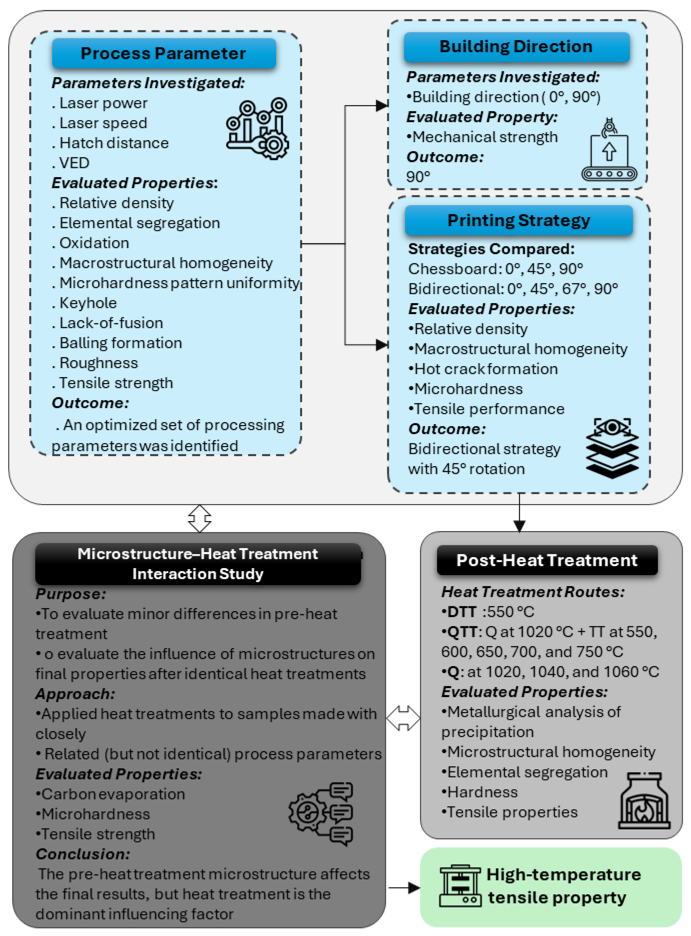
Figure 1. Overview of the optimized process parameters and heat treatments from previous studies by the authors.
Metals 15 01003 g001
Figure 3. Optical Microscopy, SEM images, and 3D diagram showing different cross-sections for (a) conventional H13, (b) AB, (c) DTT, and (d) QTT LPBF-processed H13.
Metals 15 01003 g003
Figure 4. Comparison of ductile mode feature evolution for DTT and QTT configurations between 25 and 600 °C: Low-magnification images of the DTT condition at (a) 25 (c) 300 (e) 400 (g) 500 and (i) 600 °C, respectively. Low- and high-magnification images of the QTT condition at (b) 25 (d) 300 (f) 400 (h) 500 and (j) 600 °C, respectively.
Metals 15 01003 g004
Figure 5. Comparison of ductile mode feature evolution for DTT and QTT configurations against the conventional quenched + double-tempered material at 25 and 600 °C. Conventional condition at (a) 25 °C and (d) 600 °C, DTT condition at (b) 25 °C and (e) 600 °C, QTT condition at (c) 25 °C and (f) 600 °C, respectively.
Metals 15 01003 g005
Figure 6. Stress/strain curves at different tensile testing temperatures for (a) AB; (b) DTT; (c) QTT.
Metals 15 01003 g006
Figure 7. Variation of the mechanical properties with respect to tensile testing temperature between the (a) AB, (b) DTT, and (c) QTT material.
Metals 15 01003 g007
Table 1. Experimental results for tensile testing.
AB
Sample Code T (°C)YS (MPa)UTS (MPa)El (%)
A0251052 ± 10.51832 ± 18.310.62 ± 0.32
A3300921 ± 9.21162 ± 11.66.28 ± 0.19
A4400836 ± 12.5878 ± 13.23.62 ± 0.16
A5500204 ± 3.1228 ± 3.413.87 ± 0.62
A6600176 ± 3.5188 ± 3.810.58 ± 0.63
DTT
DTT0251088 ± 10.91945 ± 19.49.45 ± 0.28
DTT3300934 ± 9.31249 ± 12.56.69 ± 0.2
DTT4400867 ± 13981 ± 14.74.33 ± 0.19
DTT5500281 ± 4.2334 ± 5.013.49 ± 0.61
DTT6600216 ± 4.3254 ± 5.111.62 ± 0.7
QTT
QTT025989 ± 9.91547 ± 15.515.66 ± 0.47
QTT3300822 ± 8.21279 ± 12.810.29 ± 0.31
QTT4400236 ± 3.5239 ± 3.610.97 ± 0.49
QTT5500159 ± 2.4169 ± 2.519.43 ± 0.87
QTT660080 ± 1.687 ± 1.721.59 ± 1.3
Disclaimer/Publisher’s Note: The statements, opinions and data contained in all publications are solely those of the individual author(s) and contributor(s) and not of MDPI and/or the editor(s). MDPI and/or the editor(s) disclaim responsibility for any injury to people or property resulting from any ideas, methods, instructions or products referred to in the content.