Article

Effect of Adding TiZr-Based Amorphous Interlayer Through Electron Beam Welding on the Microstructure and Properties of Ti/Al Joints

1
Engineering Training Center, Shenyang Aerospace University, Shenyang 110136, China
2
School of Materials Science and Engineering, Shenyang Aerospace University, Shenyang 110136, China
*
Author to whom correspondence should be addressed.
Metals 2025, 15(9), 1001; https://doi.org/10.3390/met15091001
Submission received: 3 August 2025 / Revised: 27 August 2025 / Accepted: 29 August 2025 / Published: 9 September 2025

Abstract

In this study, electron beam welding (EBW) experiments for TA1 and industrial high-purity Al were carried out, and the effects of a Ti32.8Zr30.2Cu9Ni5.3Be22.7 amorphous interlayer on the microstructure and properties of the welded joints were investigated. This is the first application of this interlayer material in the field of Ti/Al dissimilar-metal welding. In order to better improve the interfacial reaction of the welded joints and effectively control the thickness of intermetallic compounds (IMCs), the electron beam was offset by 1 mm towards the Al side. The results indicate that the amorphous interlayer was beneficial for improving the performance of the welded joints, with the maximum tensile strength reaching 94.8 MPa, which was 97% of the strength of the Al base material (97.7 MPa). The thickness of the Ti-Al intermetallic compound (IMC) layer formed in the upper part of the welded joints was lower compared with the joints without an interlayer, and the IMC layer formed in the lower part of the welded joints was only 1–2 μm. Additionally, a large number of small-sized and dispersed Ti-Al and Al-Zr IMCs were generated on the Al side, which positively impacted the performance of the welded joints.

1. Introduction

With the continuous advancement of science and technology and the increasing demand for improving the structural performance of engineering machinery, the use of dissimilar-metal composite components has become increasingly common [1,2]. Among them, Ti/Al dissimilar-metals welded structures have important application potential in aerospace, weapon equipment, transportation, and other fields due to the low density of aluminum alloys and the high strength of titanium alloys [3,4,5,6]. In recent years, many scholars have conducted extensive research on technology for welding Ti/Al dissimilar metals, such as brazing [7,8,9], friction stir welding [10,11,12], and laser welding [13,14,15]. Compared with other welding methods, electron beam welding (EBW) is increasingly used in the welding of Ti/Al dissimilar metals due to its advantages of strong penetration ability, fast welding speed, small heat-affected zone, precise control, and vacuum non-pollution [16,17,18].
The main challenge in the research of Ti/Al dissimilar-metal welding technology lies in reducing the thickness of the continuous Ti-Al IMC layer at the interface to decrease the brittleness of the joint. This can be achieved by controlling the welding parameters and adjusting the position of the heat source. Kalaiselvan et al. [19] successfully achieved effective connection between Ti6Al4V and AA2024 by offsetting the laser beam by 0.3 mm towards the aluminum alloy side, and the mechanical properties of the joints were better when the laser beam was focused on the aluminum alloy side when compared with previous studies. However, the selection of the offset amount was not systematically studied. Song et al. [20] also used laser welding to weld Ti6Al4V and A6061, with the laser beam focused on the aluminum alloy side and an offset amount of 0.3–1.2 mm selected. The results indicated that when the laser offset was 1.0 mm, the thickness of the IMC layer at the interface was only 0.26 μm, and the average tensile strength of the joint reached 203 MPa.
Changing the types and distribution of compounds at the interface by introducing intermediate materials is also a common method of improving the strength of dissimilar-metal welded joints. Cu and Nb are commonly used as interlayers for dissimilar-metal welding of titanium alloys and aluminum alloys [21,22]. In addition, the introduction of metal elements such as Ni, Zr, and Ti also inhibited the formation of Ti-Al IMCs to a certain extent [23,24,25]. However, traditional pure-metal interlayers cannot balance the multi-element reactions in the dissimilar-metal welding process due to their single composition, so it is difficult to meet the complex requirements of dissimilar-metal welding. In recent years, the use of multi-element amorphous alloys as filler metals for welding dissimilar metals has received extensive attention. Among them, TiZr-based amorphous alloys have been successfully used for welding various dissimilar metals [26,27,28,29,30]. Although not directly applied to Ti/Al welding, previous studies have reported that they can form a good metallurgical bond during the welding process of dissimilar materials such as titanium or aluminum, with no obvious defects at the interface [31,32]. In addition, their low melting point and ability to inhibit IMCs could make them suitable for Ti/Al dissimilar-metal welding.
Therefore, in this study, a TiZr-based amorphous strip was chosen as the interlayer material for EBW of TA1 and industrial high-purity Al, with the electron beam offset by 1 mm towards the Al side. This is expected to improve the weldability of Ti/Al dissimilar metals by varying the elemental distribution and phase composition in the weld due to the multicomponent elements of the amorphous alloy.

2. Materials and Methods

The base materials utilized in this study were TA1 and industrial high-purity Al plates, each with dimensions of 200 mm × 100 mm × 3 mm. The chemical compositions of the base materials are shown in Table 1. The amorphous interlayer employed was Ti32.8Zr30.2Cu9Ni5.3Be22.7 (at %), measuring ~3 mm in width and ~40 μm in thickness, and was prepared by the vacuum melt-spinning method: the raw materials, with a purity of 99.99%, were arc-remelted under a vacuum of 6 × 10⁻³ Pa to obtain a homogeneous alloy ingot; then, a the strip with a ~40 μm thickness was fabricated through the melt-spinning method. The oxide films needed to be removed from the base materials before the formal welding experiment to prevent them from having an influence on the welding quality. The method of removing oxide films from Al was to immerse the Al in a 12% NaOH aqueous solution for 5 min and then clean it with water. The method for removing oxide films from TA1 was to immerse it in a 15% HNO3 + 5% HF + 80% H2O aqueous solution for 3 min and then clean it with water. The welding experiment was completed using a THDW-15 precision vacuum electron beam welding machine manufactured in Baise, GuangXi China. Using a butt joint form with a TiZr-based amorphous interlayer inserted between the two plates, and the electron beam was offset by 1 mm towards the Al side. A schematic of the EBW process is shown in Figure 1. For the welding process, we chose a constant output beam power of 2100 W and a work chamber vacuum level of 1.0 × 10⁻³ Pa. The detailed experimental parameters are shown in Table 2. After the welding experiment, the welded joints were cut, mounted, polished, and etched according to the standard metallographic sample preparation procedure. The metallographic samples were etched using Kroll’s reagent (3 mL HF + 5 mL HNO3 + 92 mL H2O).
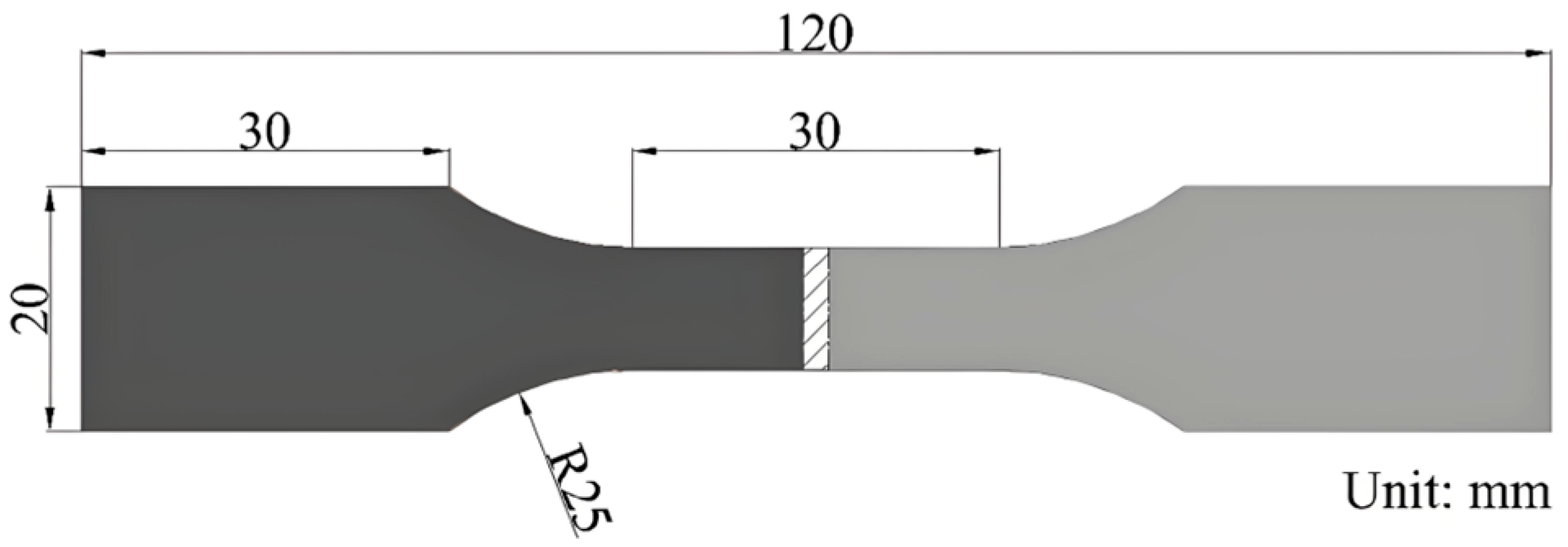
An optical microscope (OM, Olympus Corporation, Tokyo, Japan); a scanning electron microscope (SEM, Carl Zeiss AG, Oberkochen, Germany); an energy-dispersive X-ray spectrometer (EDS, Carl Zeiss AG, Oberkochen, Germany); and a micro-area X-ray diffractometer (micro-area XRD, Rigaku Corporation, Tokyo, Japan) were employed to study the microstructure of the Ti/Al joints. Tensile tests were carried out using a GOTECH Al-7000-LA20 testing machine at room temperature with a tensile rate of 0.1 mm/min. The tensile test specimens were prepared using wire-cutting equipment in accordance with the standard GB/T6396-2008 [33]. A schematic of the tensile test specimens is shown in Figure 2. In order to ensure the reliability of the tensile data, three tensile specimens for each joint were selected. The tensile capacity of the joint was evaluated using the average tensile strengths of the three tensile specimens.

3. Results

3.1. Macrostructure of Joints

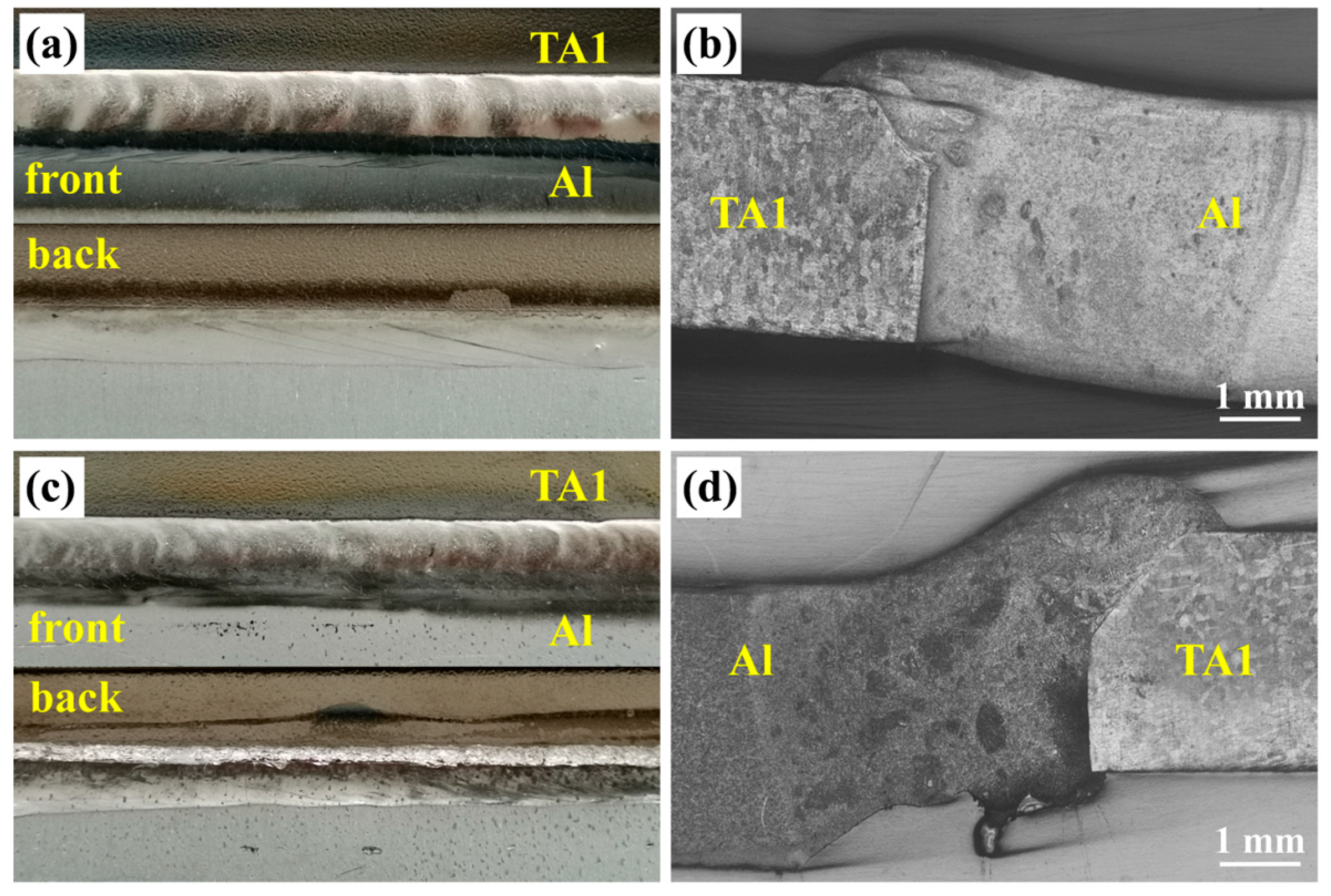
Figure 3 shows the surface appearance and corresponding cross-sections of TA1/Al EBW joints. It can be observed that the width of the weld on both the front and back was consistent, with no obvious defects on the surface and inside, which indicate that a well-formed joint can be achieved when the electron beam is offset towards the Al side and appropriate process parameters are chosen. By observing the cross-sections, it can be seen that when the electron beam was offset towards the Al side, a small amount of melting occurred at the top of the TA1 base material, while the bottom of the TA1 was not melted, and the interface between the molten Al and the non-melted TA1 was visible, forming a typical welding–brazing joint.

3.2. Microstructure of the Interface

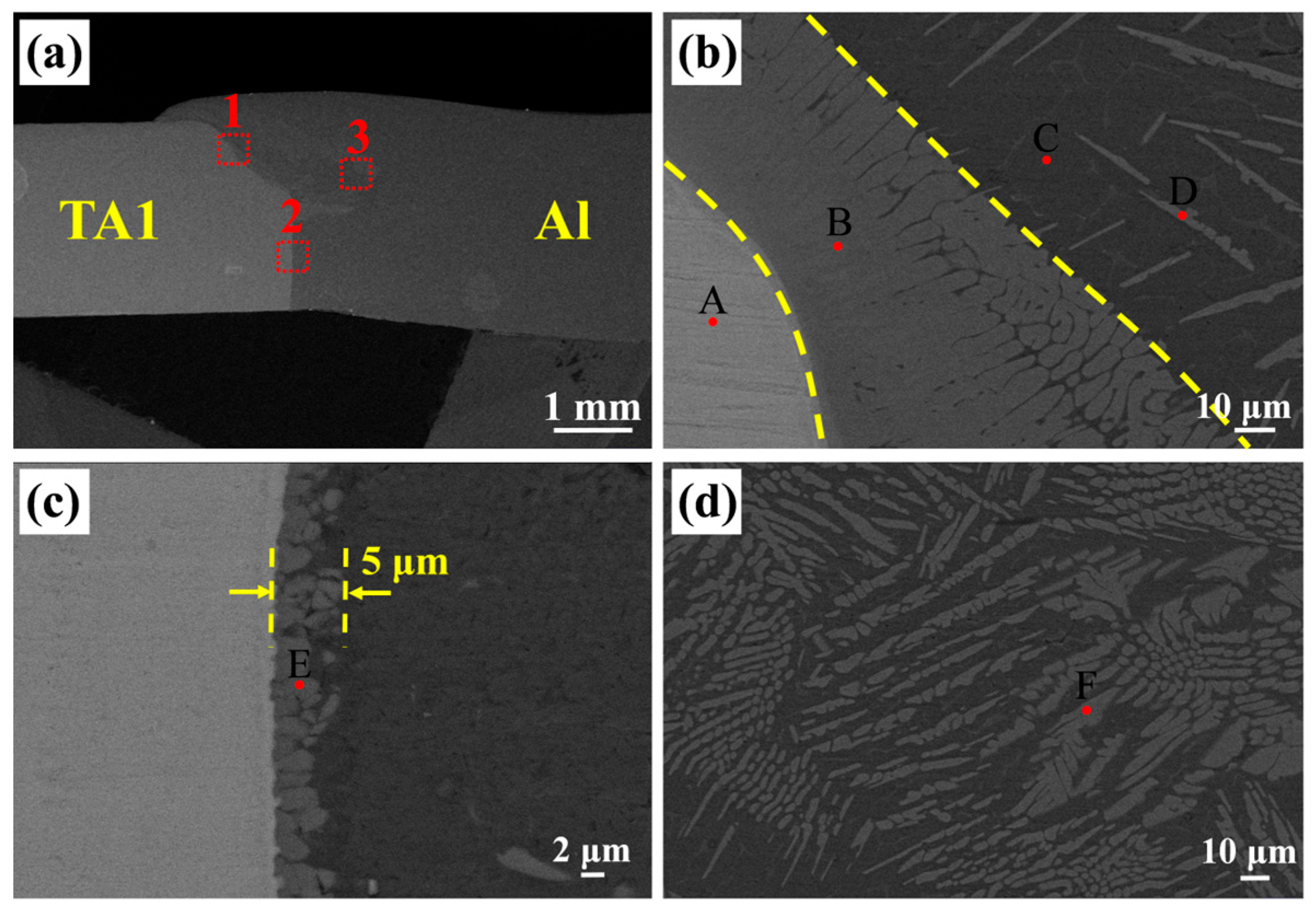
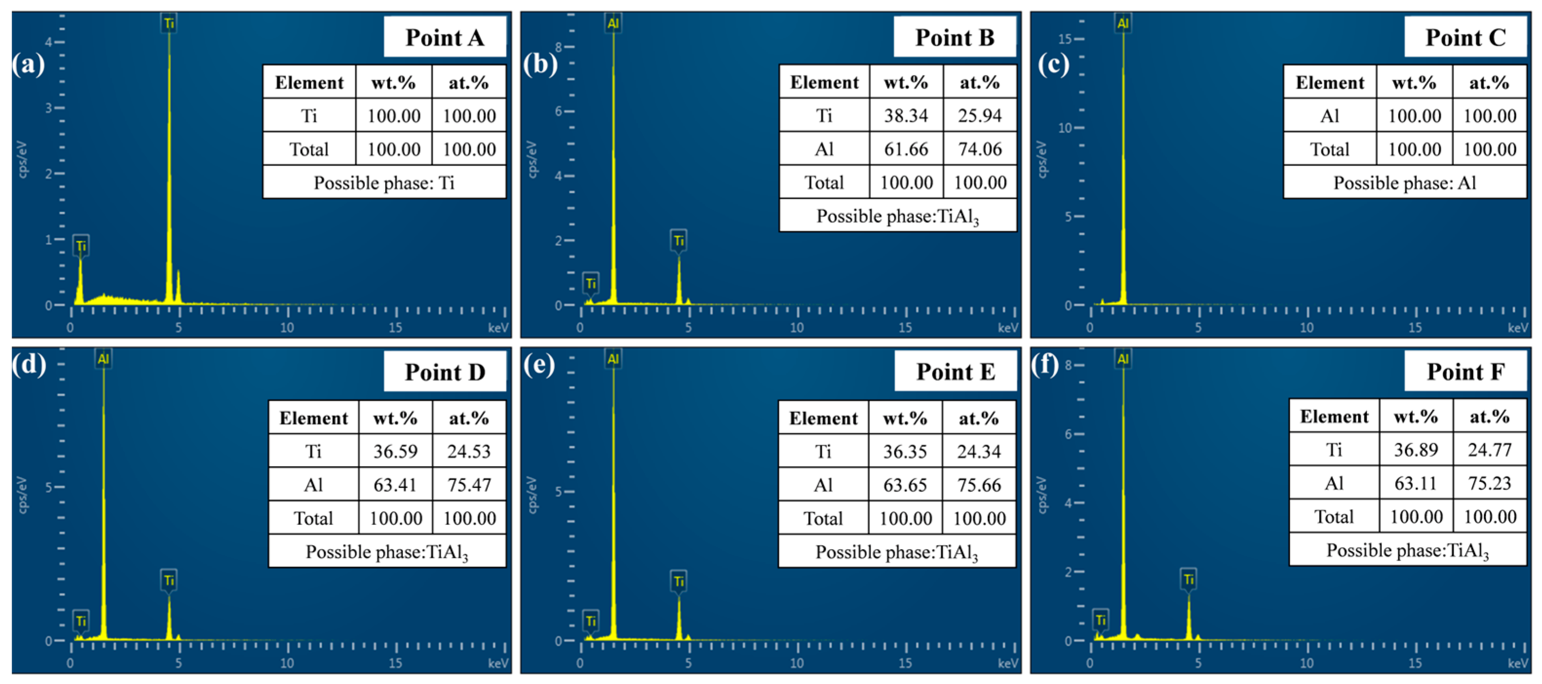
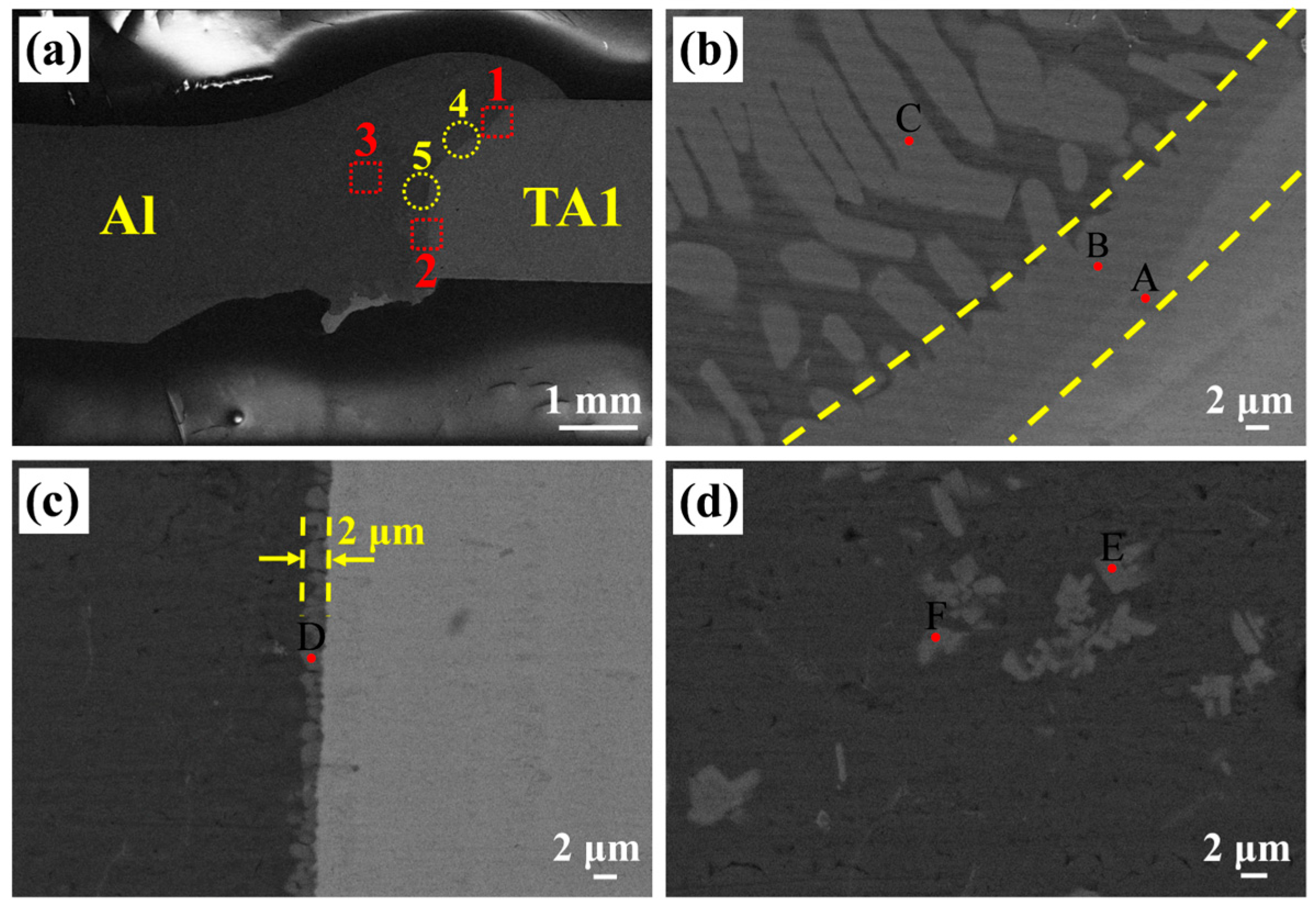
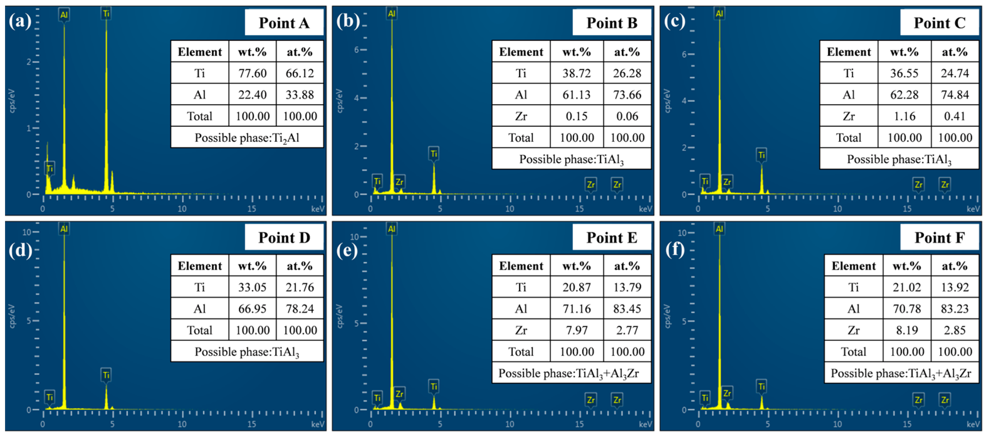
Figure 4 presents the SEM results of the Ti/Al EBW joint without an interlayer. Figure 4b–d show enlarged images of regions 1–3 in Figure 4a. The positions of points A–F in Figure 4b–d were selected for EDS analysis, and the EDS spot composition analysis results are listed in Figure 5. It can be seen that although the electron beam was offset towards the Al side, the offset distance was relatively short, and the welding heat input at the top of the joint was high, resulting in a small amount of melting in the upper part of the TA1 base material, with the interface presenting an arc-shaped curve. During the welding process, a large number of Ti and Al atoms diffused at the upper part of the interface, leading to the formation of a thick, continuous IMC reaction layer at the TA1-side interface, as shown at point B in Figure 4b. According to the EDS analysis results, the Ti-Al ratio at point B was about 1:3, suggesting that the IMC reaction layer was TiAl3. As the diffusion level of Ti atoms gradually decreased, a large number of uncontinuous long-strip IMCs were generated in the Al-side melting zone, mainly composed of TiAl3, as shown at points D and F in Figure 4b,d. The heat input in the lower part of the interface was less than that in the upper part, resulting in relatively mild reactions of different metals in this area. The electron beam energy did not melt the TA1 but activated the activity of surface Ti atoms. A small number of Ti atoms diffused over a short distance, forming a continuous cellular TiAl3 reaction layer with a thickness of 5 μm, as shown in Figure 4c.
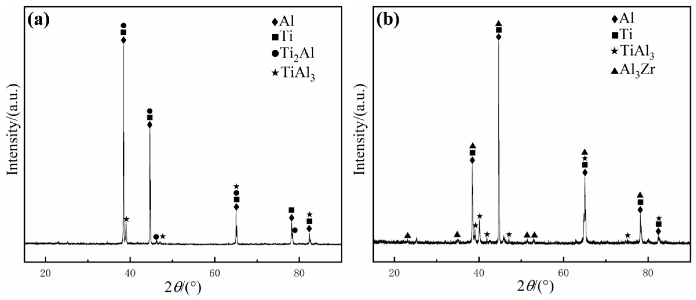
Figure 6 presents the SEM results of the Ti/Al EBW joint after adding the TiZr-based amorphous interlayer. Figure 6b–d show enlarged images of regions 1–3 in Figure 6a. The positions of points A–F in Figure 6b–d were selected for EDS analysis, and the EDS spot composition analysis results are listed in Figure 7. As can be found from Figure 6b, a small amount of melting also occurred at the top of the TA1 base material, forming a continuous IMC layer at the TA1-side interface, and rod-strip IMCs within a short distance extending to the Al side. As can be seen from a comparison with Figure 4b, the thickness of the continuous IMC layer was significantly reduced. According to the EDS analysis results, the IMC layer was composed of Ti2Al and TiAl3, while the rod-strip IMCs were mainly composed of TiAl3. The TA1 in the lower part of the welded joint was still not melted, and the boundary was vertical, forming a continuous cellular TiAl3 layer with a thickness of 1–2 μm, as shown in Figure 6c. If we compare this result with that in Figure 4c, it can be observed that the thickness of the IMC layer also decreased. Numerous dispersed and small-sized second phases were observed in the Al-side melting zone, as shown in Figure 6d, mainly composed of TiAl3 and Al3Zr according to the EDS results of points E and F. Micro-area XRD was conducted on the upper and lower parts of the interface to further verify the phase composition in the joint, with the test areas shown in regions 4 and 5 in Figure 6a. The test results are presented in Figure 8, revealing that the compounds inside the joint mainly consisted of Ti-Al IMCs and Al-Zr IMCs, which is consistent with the EDS analysis results in [34].

3.3. Tensile Strength and Fracture Analysis

The tensile properties of Ti/Al EBW joints at room temperature were investigated, as shown in Figure 9a. It can be seen that the tensile strength of the welded joint without an interlayer was 84.7 MPa. However, the tensile strength of the welded joint after adding the TiZr-based amorphous interlayer reached 94.8 MPa, which was 97% of the strength of the Al base material (97.7 MPa). Figure 9b shows the fracture morphology of the Ti/Al EBW joint after adding the TiZr-based amorphous interlayer. The fracture was located at the side of Al base material with significant necking, and the fracture surface displayed a typical dimple shape with a ductile fracture characteristic [35].
The tensile properties of the welded joints have a certain corresponding relationship with the internal structure. After adding the TiZr-based amorphous interlayer, the tensile strength of the welded joint was improved due to the reduction in the thickness of the continuous IMC layer compared to the joint without an interlayer, and the formation of dispersed and small-sized second phases. According to research, when the thickness of the reaction layer is less than 5 μm, the tensile properties of Ti/Al dissimilar-metal welded joints are significantly improved [36]. This indicates that the addition of a TiZr-based amorphous interlayer has a positive effect on improving the performance of Ti/Al dissimilar-material EBW joints.

4. Discussion

As mentioned above, the continuous IMC layer formed at the TA1 interface in Ti/Al welded joints without an interlayer was mainly TiAl3. Due to the stronger diffusion ability of Ti in Al than that of Al in Ti, an Al-rich region was formed near the TA1 interface during the mutual diffusion of Ti and Al atoms [37]. Meanwhile, according to the Ti-Al binary phase diagram and reported research results [38,39,40], TiAl3 has the lowest formation free energy (ΔG) and the highest thermodynamic stability in the Ti-Al system, so the TiAl3 phase will be formed preferentially at the TA1 interface. However, after adding the TiZr-based amorphous interlayer, the Ti element in the melted TA1 diffused together with the Ti element in the amorphous interlayer, which significantly increased the local Ti concentration on the TA1 side, promoting the preferential formation of the Ti-rich phase, and the Ti2Al IMC layer was formed first at the upper part of the interface. The formation of the Ti2Al IMC layer hindered the diffusion channels of Ti and Al atoms, resulting in a significant reduction in the thickness of the TiAl3 IMC layer formed on its basis. Although the heat input at the lower part of the joint decreased, the Ti atoms in the melted amorphous interlayer first diffused and interacted with Al atoms to form TiAl3 IMCs, which hindered the diffusion of activated Ti atoms from the TA1 surface; therefore, the thickness of the IMC layer in the lower part of the joint was also significantly reduced compared to that of the joint without an interlayer.
The types of compounds generated on the Al side also changed, with the emergence of Al-Zr IMCs in addition to Ti-Al IMCs. According to the Al-Zr [41] and Ti-Zr [42] binary phase diagrams, it was found that metallic Zr hardly dissolved in Al and was more likely to form Al-Zr IMCs with high thermal stability, and the solid solution was preferentially formed between Ti and Zr elements, which weakened the interaction between Ti and Al and reduced the thickness of the Ti-Al IMC layer at the interface. Meanwhile, the mixing enthalpy of Al and Zr is relatively negative (−44 kJ/mol), while that of Ti and Zr is close to zero, making the formation of Al-Zr IMCs more favorable [43]. In addition, as reported by Atamanenkoa et al. [44], the addition of the Zr element can enhance the grain refinement of IMCs. Combined with the fast cooling rate of electron beam welding, the size of the IMCs precipitated on the Al side in the welded joint with an amorphous interlayer was significantly reduced, as can be seen by comparing Figure 4d and Figure 6d. Although the second phase was brittle, its reduced size and dispersed distribution enhanced the effect of dispersion strengthening to some extent, thereby improving the strength of the joint.
In summary, it can be concluded that the addition of a TiZr-based amorphous interlayer effectively reduced the degree of mutual diffusion of the base material elements, prevented an increase in the thickness of the continuous IMC layer, and also changed the types and morphologies of IMCs within the interface, which could have a positive impact on the mechanical properties of Ti/Al dissimilar-metal EBW joints. According to [18], the joint strength of Ti/Al dissimilar-metal electron beam direct welding is usually lower than 60% of the strength of the base material. However, after adding a TiZr-based amorphous interlayer, the strength of the welded joint reaches 97% of the Al base material, further indicating that the TiZr-based amorphous interlayer has a positive effect on the performance of the welded joint.

5. Conclusions

This study evaluates the effect of adding a TiZr-based amorphous interlayer on the microstructure and mechanical properties of Ti/Al dissimilar-metal electron beam welding (EBW) joints. The experimental results show that the interlayer significantly suppresses the intense interdiffusion of base metal elements, reducing the thickness of the continuous Ti-Al IMC layer from about 5 μm to 2 μm, thereby effectively mitigating the adverse effects of brittle IMCs on mechanical performance.
After adding the TiZr-based amorphous interlayer, the types of compounds within the joint also change. Compared to joints without an interlayer, the Al side not only forms Ti-Al IMCs but also generates Al-Zr IMCs with significantly smaller sizes and a dispersed distribution, which can enhance the dispersion strengthening effect to a certain extent and play a positive role in improving joint performance.
In terms of mechanical properties, the tensile strength of the joint with the TiZr-based amorphous interlayer reaches 94.8 MPa, equivalent to 97% of the strength of the Al base material, with fracture occurring entirely on the Al side. Fracture analysis shows that cracks aggregate through micropores to form ductile dimples, indicating typical ductile fracture characteristics. No brittle cleavage or intergranular cracking is observed in the weld zone, confirming the effectiveness of the interlayer in suppressing the formation of brittle IMCs.
For industrial applications, the TiZr-based amorphous interlayer process proposed in this study can be directly applied to Ti/Al dissimilar-metal connection scenarios such as in aerospace lightweight components, new energy vehicle battery casings, and high-speed train body structures. It not only meets the requirements for high strength and toughness but also avoids the additional weight and corrosion risks associated with traditional mechanical joining methods.
Future work could focus on the following directions: firstly, optimizing IMCs’ size and distribution by adjusting the composition of the interlayer to balance strength and plasticity; secondly, employing multiscale numerical simulations to quantify the coupling effects of amorphous layer thickness, welding heat input, and joint performance; and finally, conducting welding experiments with aluminum and titanium alloys commonly used in industrial applications to provide more comprehensive data for research on the reliability of Ti/Al dissimilar-metal welding joints in practice.

Author Contributions

Conceptualization, B.Z., L.C., and R.X.; methodology, B.Z. and R.X.; validation, L.C. and L.Z.; formal analysis, B.Z.; investigation, R.X.; resources, B.Z. and L.Z.; data curation, L.C.; writing—original draft preparation, L.C.; writing—review and editing, B.Z.; visualization, R.X.; supervision, B.Z.; project administration, B.Z. and R.X. All authors have read and agreed to the published version of the manuscript.

Funding

This research received no external funding.

Data Availability Statement

The original contributions presented in this study are included in the article. Further inquiries can be directed to the corresponding author.

Conflicts of Interest

The authors declare no conflicts of interest.

References

  1. Baqer, Y.M.; Ramesh, S.; Yusof, F.; Manladan, S.M. Challenges and Advances in Laser Welding of Dissimilar Light Alloys: Al/Mg, Al/Ti, and Mg/Ti Alloys. Int. J. Adv. Manuf. Technol. 2018, 95, 4353–4369. [Google Scholar] [CrossRef]
  2. Kuryntsev, S. A Review: Laser Welding of Dissimilar Materials (Al/Fe, Al/Ti, Al/Cu)—Methods and Techniques, Microstructure and Properties. Materials 2021, 15, 122. [Google Scholar] [CrossRef]
  3. Xie, J.; Zhang, W.; Chen, Y.; Zhang, L.; Yin, L.; Zhang, T.; Wang, S. Interfacial Microstructure and Mechanical Properties of the Al/Ti Joint by Magnetic Pulse Welding. Mater. Charact. 2022, 194, 112462. [Google Scholar] [CrossRef]
  4. Li, Z.; Peng, W.; Chen, Y.; Liu, W.; Zhang, H. Simulation and Experimental Analysis of Al/Ti Plate Magnetic Pulse Welding Based on Multi-Seams Coil. J. Manuf. Process. 2022, 83, 290–299. [Google Scholar] [CrossRef]
  5. Krishna, L.R.; Madhavi, Y.; Sahithi, T.; Rao, D.S.; Ijeri, V.S.; Prakash, O.; Gaydos, S.P. Enhancing the High Cycle Fatigue Life of High Strength Aluminum Alloys for Aerospace Applications. Fatigue Fract. Eng. Mater. Struct. 2019, 42, 698–709. [Google Scholar] [CrossRef]
  6. Williams, J.C.; Boyer, R.R. Opportunities and Issues in the Application of Titanium Alloys for Aerospace Components. Metals 2020, 10, 705. [Google Scholar] [CrossRef]
  7. Li, Z.; Zhang, Y.; Yang, Y.; Feng, J.; Zhang, L. Properties Study on Ti/Al Butt Joining by GMAW/GTAW Hybrid Welding-Brazing. Mater. Res. Express 2023, 10, 116518. [Google Scholar] [CrossRef]
  8. Miao, Y.; Ma, Z.; Yang, X.; Liu, J.; Han, D. Experimental Study on Microstructure and Mechanical Properties of AA6061/Ti-6Al-4V Joints Made by Bypass-Current MIG Welding-Brazing. J. Mater. Process Technol. 2018, 260, 104–111. [Google Scholar] [CrossRef]
  9. Zhang, Y.; Huang, J.; Ye, Z.; Cheng, Z.; Yang, J.; Chen, S. Influence of Welding Parameters on the IMCs and the Mechanical Properties of Ti/Al Butt Joints Welded by MIG/TIG Double-Sided Arc Welding-Brazing. J. Alloys Compd. 2018, 747, 764–771. [Google Scholar] [CrossRef]
  10. Zhao, H.; Yu, M.; Jiang, Z.; Zhou, L.; Song, X. Interfacial Microstructure and Mechanical Properties of Al/Ti Dissimilar Joints Fabricated via Friction Stir Welding. J. Alloys Compd. 2019, 789, 139–149. [Google Scholar] [CrossRef]
  11. Li, Y.; Zhang, X.; Shi, L.; Wu, C.; Li, S.; Gao, S. Double Side Friction Stir Z Shape Butt Lap Welding of Dissimilar Titanium Aluminum Alloys. Int. J. Mech. Sci. 2024, 271, 109135. [Google Scholar] [CrossRef]
  12. Geyer, M.; Avettand-Fènoël, M.-N.; Vidal, V.; Rezaï-Aria, F.; Boher, C. Multi-Scale Effects of the Tool Shape and Length on the Interfacial Microstructure and the Mechanical Behaviour of Al2024/Ti-6Al-4V Lap Friction Stir Welds. J. Manuf. Process. 2024, 113, 360–372. [Google Scholar] [CrossRef]
  13. Zhou, J.; Zhou, D. Laser Welding of TC4 Titanium Alloy to 7075 Aluminum Alloy with Infinite-Shape Oscillating Beam. Opt. Laser Technol. 2023, 160, 109044. [Google Scholar] [CrossRef]
  14. Chen, Z.; Cai, C.; Yu, J.; Huang, J.; Chen, H.; Li, L. Microstructure Evolution and Fracture Behavior of Laser Welded-Brazed Titanium/Aluminum Joints with Various Gap Sizes. J. Mater. Res. Technol. 2024, 29, 714–727. [Google Scholar] [CrossRef]
  15. Zhou, J.; Zhou, D.; Liu, J. Effect of Oscillating Laser Beam on the Interface and Mechanical Properties of Ti/Al Fusion Welding Joint. J. Mater. Res. Technol. 2022, 19, 1993–2007. [Google Scholar] [CrossRef]
  16. Wang, T.; Li, X.; Zhang, Y.; Li, H.; Zhang, B.; Feng, J. Regulating the Interfacial Morphology of Electron Beam Welded Pure Ti/2024Al Dissimilar Joint. J. Mater. Process. Technol. 2017, 245, 227–231. [Google Scholar] [CrossRef]
  17. Basude, A.; Kumar, A.; Rajasingh, G.; Kishore, M.K. Electron Beam Welding of Dissimilar Titanium to Aluminium: Interface Microstructure and Mechanical Properties. Proc. Inst. Mech. Eng. Part E J. Process. Mech. Eng. 2023, 239, 800–810. [Google Scholar] [CrossRef]
  18. Anchev, A.; Kaisheva, D.; Kotlarski, G.; Dunchev, V.; Stoyanov, B.; Ormanova, M.; Atanasova, M.; Todorov, V.; Daskalova, P.; Valkov, S. Welding of Ti6Al4V and Al6082-T6 Alloys by a Scanning Electron Beam. Metals 2023, 13, 1252. [Google Scholar] [CrossRef]
  19. Kalaiselvan, K.; Elango, A.; Nagarajan, N.M.; Sekar, K. Studies on Characteristics of Ti6Al4V/AA2024 Dissimilar Weld Joint Using Laser Beam Focusing from AA2024 Side. Trans. Indian Inst. Met. 2017, 70, 2147–2153. [Google Scholar] [CrossRef]
  20. Song, Z.; Nakata, K.; Wu, A.; Liao, J. Interfacial Microstructure and Mechanical Property of Ti6Al4V/A6061 Dissimilar Joint by Direct Laser Brazing without Filler Metal and Groove. Mater. Sci. Eng. A 2013, 560, 111–120. [Google Scholar] [CrossRef]
  21. Iltaf, A.; Dehghan, S.; Barka, N.; Belzile, C. Laser Butt Welding of AA7075 Aluminium Alloy and Ti6Al4V Titanium Alloy Using a Cu Interlayer. Mater. Sci. Technol. 2024, 40, 1015–1020. [Google Scholar] [CrossRef]
  22. Zhou, J.; Zhou, D.; Li, H. Effect of Adding Nb Foil on Joint Properties of Laser Fusion Welding for TC4 Titanium and 7075 Aluminum Alloy. Chin. J. Aeronaut. 2023, 36, 508–521. [Google Scholar] [CrossRef]
  23. Gu, X.; Zhang, L. Laser Lap Welding of TC4 Titanium Alloy to 6082 Aluminum Alloy Using a CoNiCuNb0.5 V1.5 High Entropy Alloy Filler. Mater. Lett. 2022, 312, 131562. [Google Scholar] [CrossRef]
  24. Lv, S.; Cui, Q.; Huang, Y.; Jing, X. Influence of Zr Addition on TIG Welding–Brazing of Ti–6Al–4V toAl5A06. Mater. Sci. Eng. A 2013, 568, 150–154. [Google Scholar] [CrossRef]
  25. Zhang, Z.; Huang, J.; Fu, J.; Nie, P.; Zhang, S. Microstructure and mechanical properties of laser welded-brazed titanium/aluminum joints assisted by titanium mesh interlayer. J. Mater. Process. Technol. 2022, 302, 117502. [Google Scholar] [CrossRef]
  26. Xia, Y.; Ma, Z.; Du, Q.; Jiu, Y.; Guo, P.; Qin, J.; Li, S.; Zhang, X.; Zhou, P.; Hu, J.; et al. Microstructure and Properties of the TiAl/GH3030 Dissimilar Joints Vacuum-Brazed with a Ti-Based Amorphous Filler Metal. Mater. Charact. 2024, 207, 113520. [Google Scholar] [CrossRef]
  27. Zhang, L.; Dong, H.; Li, P.; Li, S.; Wu, B.; Ma, Y.; Huang, L.; Li, C.; Li, J.; Yang, Y. Vacuum Brazing TiAl Intermetallic to K4169 Alloy Using Amorphous Filler Metals Ti56.25−xZrxNi25Cu18.75. J. Mater. Sci. Technol. 2023, 154, 217–231. [Google Scholar] [CrossRef]
  28. Pang, S.; Sun, L.; Xiong, H.; Chen, C.; Liu, Y.; Li, H.; Zhang, T. A Multicomponent TiZr-Based Amorphous Brazing Filler Metal for High-Strength Joining of Titanium Alloy. Scr. Mater. 2016, 117, 55–59. [Google Scholar] [CrossRef]
  29. Xia, Y.; Dong, H.; Zhang, R.; Wang, Y.; Hao, X.; Li, P.; Dong, C. Interfacial microstructure and shear strength of Ti6Al4V alloy/316L stainless steel joint brazed with Ti33.3Zr16.7Cu50−xNix amorphous filler metals. Mater. Des. 2020, 187, 108380. [Google Scholar] [CrossRef]
  30. Xia, Y.; Dong, H.; Li, P. Brazing TC4 Titanium Alloy/316L Stainless Steel Joint with Ti50−xZrxCu39Ni11 Amorphous FillerMetals. J. Alloys Compd. 2020, 849, 156650. [Google Scholar] [CrossRef]
  31. Lazurenko, D.V.; Ivannikov, A.A.; Anisimov, A.G.; Popov, N.S.; Dovzhenko, G.D.; Bataev, I.A.; Emurlaev, K.I.; Ogneva, T.S.; Golovin, E.D. Joining Ti-based metallic glass and crystalline titanium by magnetic pulse welding. J. Non-Cryst. Solids 2022, 597, 121912. [Google Scholar] [CrossRef]
  32. Liang, H.L.; Luo, N.; Shen, T.; Sun, X.; Fan, X.R.; Cao, Y. Experimental and numerical simulation study of Zr-based BMG/Al composites manufactured by underwater explosive welding. J. Mater. Res. Technol. 2020, 9, 1539–1548. [Google Scholar] [CrossRef]
  33. GB/T6396-2008; Clad Steel Plates—Mechanical and Technological Test. Standards Press of China: Beijing, China, 2008.
  34. Padhamnath, P.; Kusmierczyk, F.; Kopyscianski, M.; Gondek, L.; Migas, P.; Karbowniczek, M. Realization of a Novel FeSiAlCuSn Multicomponent Alloy and Characterization of Intermetallic Phases Formed at Different Temperatures During Cooling. Metals 2025, 15, 479. [Google Scholar] [CrossRef]
  35. Noell, P.J.; Carroll, J.D.; Boyce, B.L. The mechanisms of ductile rupture. Acta Mater. 2018, 161, 83–98. [Google Scholar] [CrossRef]
  36. Chen, X.; Lei, Z.L.; Chen, Y.B.; Han, Y.; Jiang, M.; Tian, Z.; Bi, J.; Lin, S.B. Microstructure and tensile properties of Ti/Al dissimilar joint by laser welding-brazing at subatmospheric pressure. J. Manuf. Process. 2020, 56, 19–27. [Google Scholar] [CrossRef]
  37. Lv, S.X.; Jing, X.J.; Huang, Y.X.; Xu, Y.Q.; Zheng, C.Q.; Yang, S.Q. Investigation on TIG Arc Welding–Brazing of Ti/Al Dissimilar Alloys with Al Based Fillers. Sci. Technol. Weld. Join. 2012, 17, 519–524. [Google Scholar] [CrossRef]
  38. Huang, X.-M.; Cai, G.-M.; Liu, H.-S. Phase Equilibria and Transformation in the Ti–Al–Ta System. J. Mater. Sci. 2022, 57, 2163–2179. [Google Scholar] [CrossRef]
  39. Zhou, X.; Cao, X.; Zhang, F.; Chen, Z.; Duan, J. Effects of AlSi12 Interlayer on Microstructure and Mechanical Properties of Laser Welded 5A06/Ti6Al4V Joints. Weld. World 2021, 65, 1389–1402. [Google Scholar] [CrossRef]
  40. Zhang, J.; Gao, J.; Song, B.; Zhang, L.; Han, C.; Cai, C.; Zhou, K.; Shi, Y. A Novel Crack-Free Ti-Modified Al-Cu-Mg Alloy Designed for Selective Laser Melting. Addit. Manuf. 2021, 38, 101829. [Google Scholar] [CrossRef]
  41. Pozdniakov, A.V.; Barkov, R.Y.; Prosviryakov, A.S.; Churyumov, A.Y.; Golovin, I.S.; Zolotorevskiy, V.S. Effect of Zr on the Microstructure, Recrystallization Behavior, Mechanical Properties and Electrical Conductivity of the Novel Al-Er-Y Alloy. J. Alloys Compd. 2018, 765, 1–6. [Google Scholar] [CrossRef]
  42. Zhao, Q.; Ueno, T.; Wakabayashi, N. A Review in Titanium-Zirconium Binary Alloy for Use in Dental Implants: Is There an Ideal Ti-Zr Composing Ratio? Jpn. Dent. Sci. Rev. 2023, 59, 28–37. [Google Scholar] [CrossRef] [PubMed]
  43. Takeuchi, A.; Inoue, A. Classification of Bulk Metallic Glasses by Atomic Size Difference, Heat of Mixing and Period of Constituent Elements and Its Application to Characterization of the Main Alloying Element. Mater. Trans. 2005, 46, 2817–2829. [Google Scholar] [CrossRef]
  44. Atamanenko, T.V.; Eskin, D.G.; Sluiter, M.; Katgerman, L. On the Mechanism of Grain Refinement in Al–Zr–Ti Alloys. J. Alloys Compd. 2011, 509, 57–60. [Google Scholar] [CrossRef]
Figure 1. Schematic of EBW process.
Metals 15 01001 g001
Figure 2. Schematic of tensile test specimens.
Metals 15 01001 g002
Figure 3. Surface appearance and corresponding cross-sections of TA1/Al EBW joints: (a,b) without interlayer; (c,d) with amorphous interlayer.
Metals 15 01001 g003
Figure 4. Backscattered electron images of the interfacial microstructure of the welded joint without an interlayer: (a) macromorphology; (bd) micromorphology of regions 1–3 in Figure 4a.
Metals 15 01001 g004
Figure 5. Results of EDS spot composition analysis of points A–F in Figure 4b–d. (a) point A; (b) point B; (c) point C; (d) point D; (e) point E; (f) point F.
Metals 15 01001 g005
Figure 6. Backscattered electron images of the interfacial microstructure of the welded joint after adding an interlayer: (a) macromorphology; (bd) micromorphology of regions 1–3 in Figure 6a.
Metals 15 01001 g006
Figure 7. Results of EDS spot composition analysis of points A–F in Figure 6b–d. (a) point A; (b) point B; (c) point C; (d) point D; (e) point E; (f) point F.
Metals 15 01001 g007
Figure 8. XRD patterns at the interface: (a) region 4; (b) region 5.
Metals 15 01001 g008
Figure 9. (a) Tensile stress–strain curves; (b) fracture morphology of joint after adding interlayer.
Metals 15 01001 g009
Table 1. Chemical composition of base materials (wt. %).
ElementsFeCuSiNCHOAlTi
TA10.2--0.030.080.0150.18-Bal.
Al0.0030.0030.003----Bal.-
Table 2. EBW process parameters.
Welding ParametersValue
Accelerating voltage, kV60
Welding speed, mm/min1000
Beam current, mA35
Focusing current, mA413
Disclaimer/Publisher’s Note: The statements, opinions and data contained in all publications are solely those of the individual author(s) and contributor(s) and not of MDPI and/or the editor(s). MDPI and/or the editor(s) disclaim responsibility for any injury to people or property resulting from any ideas, methods, instructions or products referred to in the content.