2. Materials and Methods
Empirical observations of defect occurrences were conducted on the product “Bearing ring” (
Figure 1), designed for gearbox applications as a combined component of a bearing housing and a force transmission converter. The product features a simple geometric shape—a rotational cylinder with a central hole and a non-uniform cross-section.
The product dimensions are as follows: outer diameter—Ø 155 mm, inner diameter of the central hole—Ø 98 mm, height—63 mm, and the weight of the forging is approximately 4 kg.
The forging is manufactured from 42CrMo4 steel, classified according to ISO 683-2:2016 [
15]. The material is normalized, annealed, and hardened to achieve the prescribed mechanical properties.
After machining operations, specific areas of the product undergo surface hardening to increase hardness, followed by grinding to reduce surface roughness.
The technological and production operations for the forging of the bearing ring are summarized in
Table 1. The heating of the billet is performed in a continuous induction furnace at a temperature range of 1160 to 1220 °C.
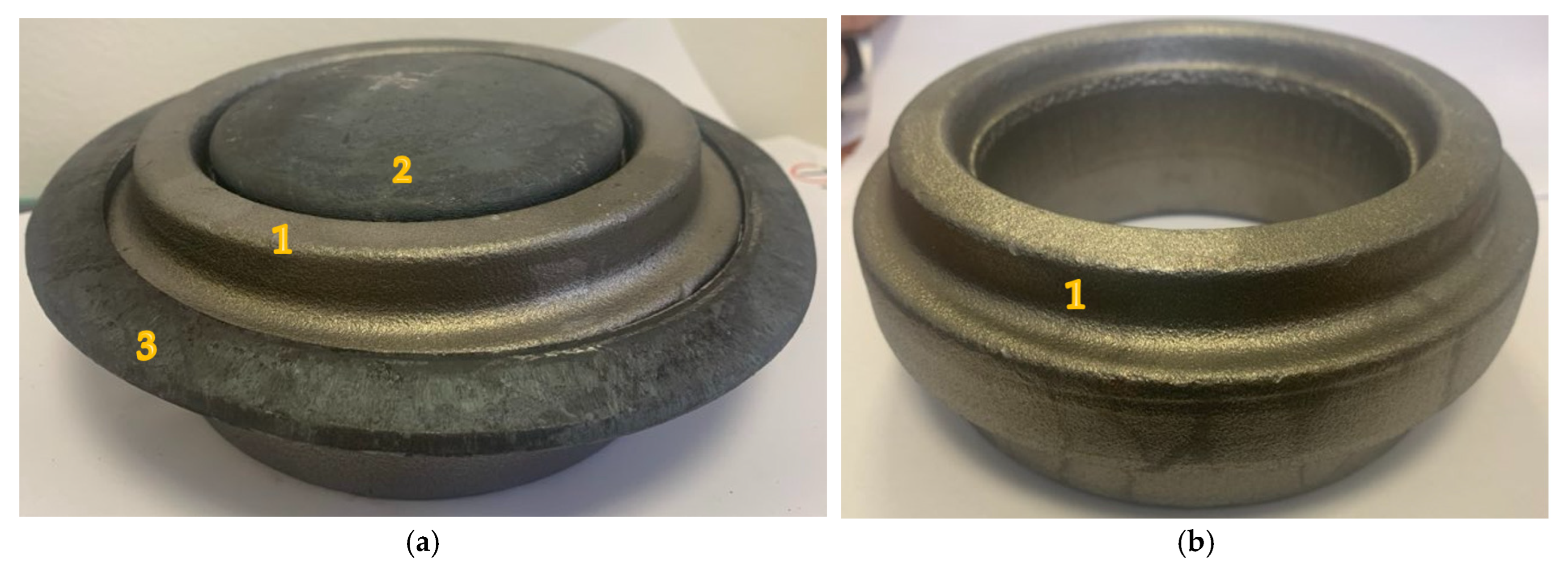
The forging of the “bearing ring” is carried out on a mechanical forging press with a maximum working force of 25,000 kN. Forging tools for this operation are designed to combine two stages of forging (
Figure 2a):
Pre-forging (open-die): This phase involves reducing the billet to the desired height of the preform and shaping it to prepare for the next phase.
Final forging (closed-die): This phase involves filling the forging cavity to achieve the desired shape of the forging. The result includes a slug for the central hole and flash along the edges of the forging.
Subsequently, on a separate machine—a mechanical press with a maximum working force of 5000 kN—the forging (1) undergoes slug (2) and flash (3) removal. In the first phase, a punching pin removes the slug-membrane from the inner hole of the forging. In the second phase, a cutting plate is used to trim the flash, achieving the final shape and dimensions of the forging (
Figure 2b).
After forging, the product undergoes a heat treatment process consisting of normalization annealing, quenching, and tempering. Normalization annealing is carried out in continuous gas furnaces with electronically controlled temperature systems that comply with the DIN 17052-1 [
16] standard (requirements for temperature uniformity). The process is conducted at a temperature of 870 °C with a holding time of 30 min.
Quenching is performed in a continuous gas furnace, also at a temperature of 870 °C, followed by immersion into a synthetic polymer quenching medium at 25 °C for a soaking time of 30 s. Subsequently, the products pass through a continuous electric tempering furnace at a temperature of 660 °C with a holding time of 2.5 h.
Once cooled, the forgings are shot-blasted in a shot blasting machine to remove surface impurities and prepare them for final quality control.
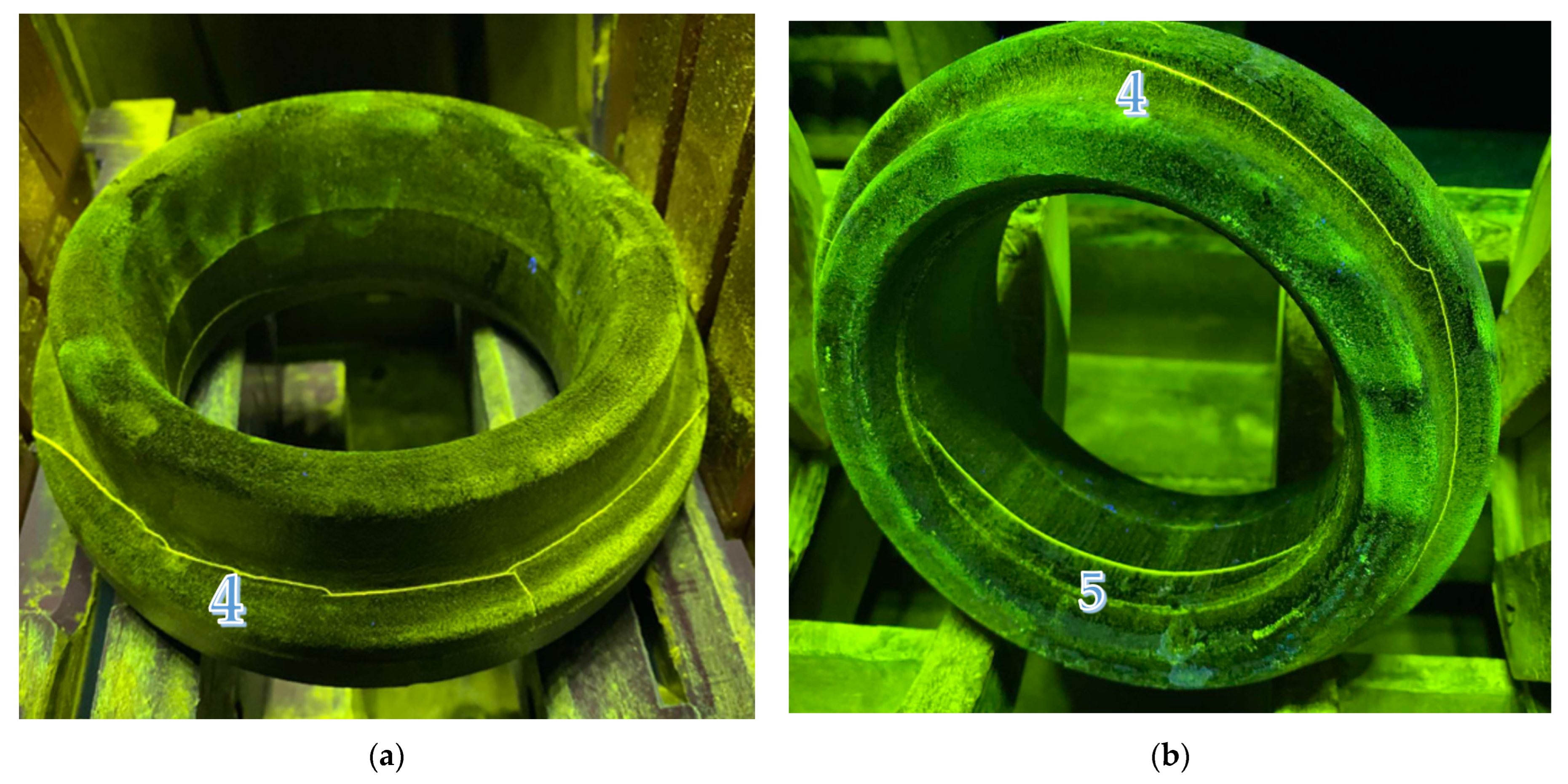
The forgings were subjected to non-destructive testing. The first phase involved visual inspection according to EN 13018:2016 [
17], followed by magnetic particle inspection in the second phase, performed in accordance with EN 10228-1:2016 [
18].
To assess the mechanical properties, conduct chemical analyses, and perform metallographic observations, a cross-section of the test sample was prepared.
For chemical composition analysis, the method of optical emission spectroscopy was employed (SPECTRO Analytical Instruments GmbH, Kleve, GERMANY). The chemical composition of individual batches is presented in
Table 2. The results of the elemental analyses fall within the specified limits for 42CrMo4 steel.
To determine the
PC cracking parameter, the method according to Ita and Bessy was used, which combines the amount of individual chemical elements in the steel composition, the thickness of the steel product (
t), and the amount of diffusible hydrogen (
H):
The Charpy impact test was used to evaluate the impact toughness, in accordance with EN ISO 148-1:2016 [
19]. The results of the impact toughness tests are presented in
Table 3, meeting the required limit (KV + 20 °C, minimum 35 J) for 42CrMo4 steel in the N + QT condition.
The Brinell hardness test was conducted in accordance with EN ISO 6506-1:2014 [
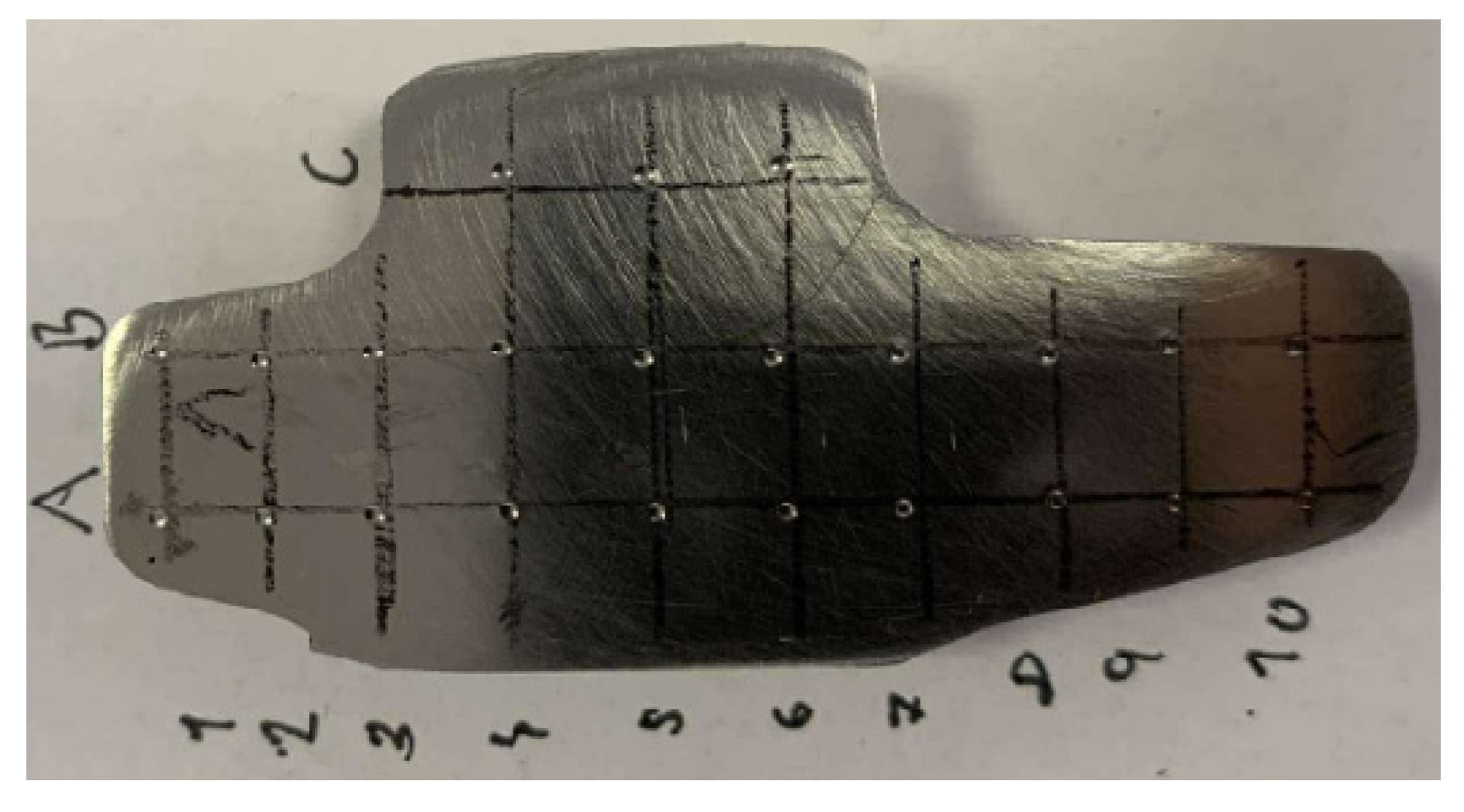
20]. The measured surface hardness for batch 63813 is 278 HB, and for batch T21297, it is 272 HB. The specified hardness for the tested forging (bearing ring) is in the range of 240–270 HB.
Author Contributions
Conceptualization, J.B. and M.G.; methodology: M.G.; validation, J.B. and M.G.; formal analysis, J.B.; investigation M.G.; sources, M.G.; data curation, J.B.; writing—preparation of initial draft, M.G.; writing—checking and editing, J.B.; visualization, M.G.; supervision, J.B.; project administration, J.B.; fundraising, J.B. All authors have read and agreed to the published version of the manuscript.
Funding
This research is the result of the project supported by the Slovak Research and Development Agency, the Scientific Grant Agency, “Possibilities of application of laser additive technologies in restoration of functional surfaces” (1/0597/23), and the Cultural and Educational Grant Agency, “Increase of knowledge, abilities and skills of graduates in the use of IT tools for modelling and simulation of technological processes of processing of new and newly developed materials” (018TUKE-4/2024) and “Innovative approaches in the restoration of functional surfaces by laser surfacing” APVV-20-0303.
Data Availability Statement
The original contributions presented in the study are included in the article, further inquiries can be directed to the corresponding author.
Conflicts of Interest
The authors declare no conflicts of interest.
References
- Suzuki, K.; Sato, I.; Kusuhashi, M.; Tsukada, H. Current steel forgings and their properties for steam generator of nuclear power plant. Nucl. Eng. Des. 2000, 198, 15–23. [Google Scholar] [CrossRef]
- Skubisz, P.; Lisiecki, L. Effect of forging sequence and heat treatment on microstructure of high-duty power-plant shaft made of Cr-Mo ultra-high strength steel. J. Min. Metall. Sect. B 2023, 59, 299–314. [Google Scholar] [CrossRef]
- Dieter, G.E. Material Factors Affecting Workability. In Handbook of Workabilit and Process Design; ASM International: Materials Park, OH, USA, 1993; Volume 14, pp. 782–794. [Google Scholar]
- Dieter, G.E. Forging Defects. In Handbook Forming and Forging; ASM International: Materials Park, OH, USA, 1993; Volume 14, pp. 834–841. [Google Scholar]
- EN 1011-2:2001/A1:2023; Welding—Recommendations for Welding of Metallic Materials—Part 2: Arc Welding of Ferritic Steels. CEN-CENELEC Management Centre: Brussels, Belgium, 2023; p. 6.
- Viňáš, J.; Brezinová, J.; Maňková, I.; Brezina, J. Technologies and Defectoscopic Testing of Materials, 1st ed.; Study Literature Edition: Košice, Slovakia, 2021; pp. 6–55. [Google Scholar]
- Pei, W.; Dong, J.; Ji, H.; Long, H.; Yang, S. Study on crack propagation of 42CrMo. Metalurgija 2019, 58, 219–222. Available online: https://hrcak.srce.hr/218357 (accessed on 5 August 2025).
- Kakimoto, H.; Arikawa, T. Prediction of Surface Crack in Hot Forging by Numerical Simulation. Procedia Eng. 2014, 81, 474–479. [Google Scholar] [CrossRef]
- Ito, Y.; Bessyo, K. Cracking parameter of high strength steels related to heat affected zone cracking. J. Jpn. Weld. Soc. 1968, 37, 983–991. [Google Scholar] [CrossRef]
- Bilbao, O.; Loizaga, I.; Alonso, J.; Girot, F.; Torregaray, A. 42CrMo4 steel flow behavior characterization for high temperature closed dies hot forging in automotive components applications. Heliyon 2023, 9, e22256. [Google Scholar] [CrossRef] [PubMed]
- Kohls, E.; Heinzel, C.; Eich, M. Evaluation of Hardness and Residual Stress Changes of AISI 4140 Steel Due to Thermal Load during Surface Grinding. J. Manuf. Mater. Process. 2021, 5, 73. [Google Scholar] [CrossRef]
- Borisov, I. Properties and defects of large forgings. Met. Sci. Heat Treat. 1998, 40, 316–318. [Google Scholar] [CrossRef]
- Huang, Y.; Lin, Y.; Deng, J.; Liu, G.; Chen, M. Hot tensile deformation behaviors and constitutive model of 42CrMo steel. Mater. Des. 2014, 53, 349–356. [Google Scholar] [CrossRef]
- Lin, Y.; Chen, M.; Zhong, J. Microstructural evolution in 42CrMo steel during compression at elevated temperatures. Mater. Lett. 2008, 62, 2132–2135. [Google Scholar] [CrossRef]
- ISO 683-2:2016; Heat-Treatable Steels, Alloy Steels and Free-Cutting Steels-Part 2: Alloy Steels for Quenching and Tempering. ISO International Organization for Standardization: Geneve, Switzerland, 2016; p. 10.
- DIN 17052-1:2013-09; Heat Treatment Furnaces—Part 1: Requirements for Temperature Uniformity. DIN German Institute for Standardization: Berlin, Germany, 2013.
- EN 13018:2016; Non-Destructive Testing—Visual Testing—General Principles. CEN-CENELEC Management Centre: Brussels, Belgium, 2016.
- EN 10228-1:2016; Non-Destructive Testing of Steel Forgings—Part 1: Magnetic Particle Inspection. CEN-CENELEC Management Centre: Brussels, Belgium, 2016.
- ISO 148-1:2016; Metallic Materials—Charpy Pendulum Impact Test Part 1: Test Method. ISO International Organization for Standardization: Geneve, Switzerland, 2016.
- ISO 6506-1:2014; Metallic Materials—Brinell Hardness Test Part 1: Test Method. ISO International Organization for Standardization: Geneve, Switzerland, 2014.
- Brziak, P.; Piussi, V.; Bernasovský, P.; Grgač, P.; Mráz, Ľ.; Hrivňák, I.; Kálna, K.; Pecha, J.; Országhová, J.; Blaškovitš, P.; et al. Materials and Their Welding Behavior; Welding Research Institute—Industrial Institute SR: Bratislava, Slovakia, 2014; p. 117. [Google Scholar]
- Saha, D.; Chang, I.; Park, Y. Heat-affected zone liquation crack on resistance spot welded TWIP steels. Mater. Charact. 2014, 93, 40–51. [Google Scholar] [CrossRef]
- Schmitz, W. ForgeBase–A Tool for Optimization of the Open-Die Forging Process, In Proceedings of the 15th International Forgemasters Meeting, Kobe, Japan, 26–29 October 2003.
- Knap, M.; Kugler, G.; Palkowski, H.; Turk, R. Prediction of material spreading in hot open-die forging. Steel Res. Int. 2004, 75, 405–410. [Google Scholar] [CrossRef]
- Han, J.; Zhao, G.; Cao, Q. Internal crack recovery of 20MnMo steel. Sci. China Ser. E Technol. Sci. 1997, 40, 164–169. [Google Scholar] [CrossRef]
- Ma, Q.; Wang, Z.; Zhong, Y. The mechanism of faults originating from inclusions in the plastic deformation processes of heavy forging. J. Mater. Process. Technol. 2002, 123, 61–66. [Google Scholar] [CrossRef]
- EN ISO 17641-1:2004; Destructive Tests on Welds in Metallic Materials—Hot Cracking Tests for Weldments—Arc Welding Processes—Part 1: General. ISO/CEN: Geneva, Switzerland; Brussels, Belgium, 2004.
Figure 1.
Final product—bearing ring.
Figure 2.
Forging bearing ring (1): (a) forging with inner slug (2) and outside flash (3); (b) forging after cutting slug and flash.
Figure 3.
Inspected forging in magnetic testing (MT): (a) location of cracks on the outside (4) of the forging; (b) location of cracks on the inside of the forging (5) and on the outside wall of the forging.
Figure 4.
Inspected forging in section: (a) location of cracks on forging from batch 63813; (b) location of cracks on forging from batch T21297.
Figure 5.
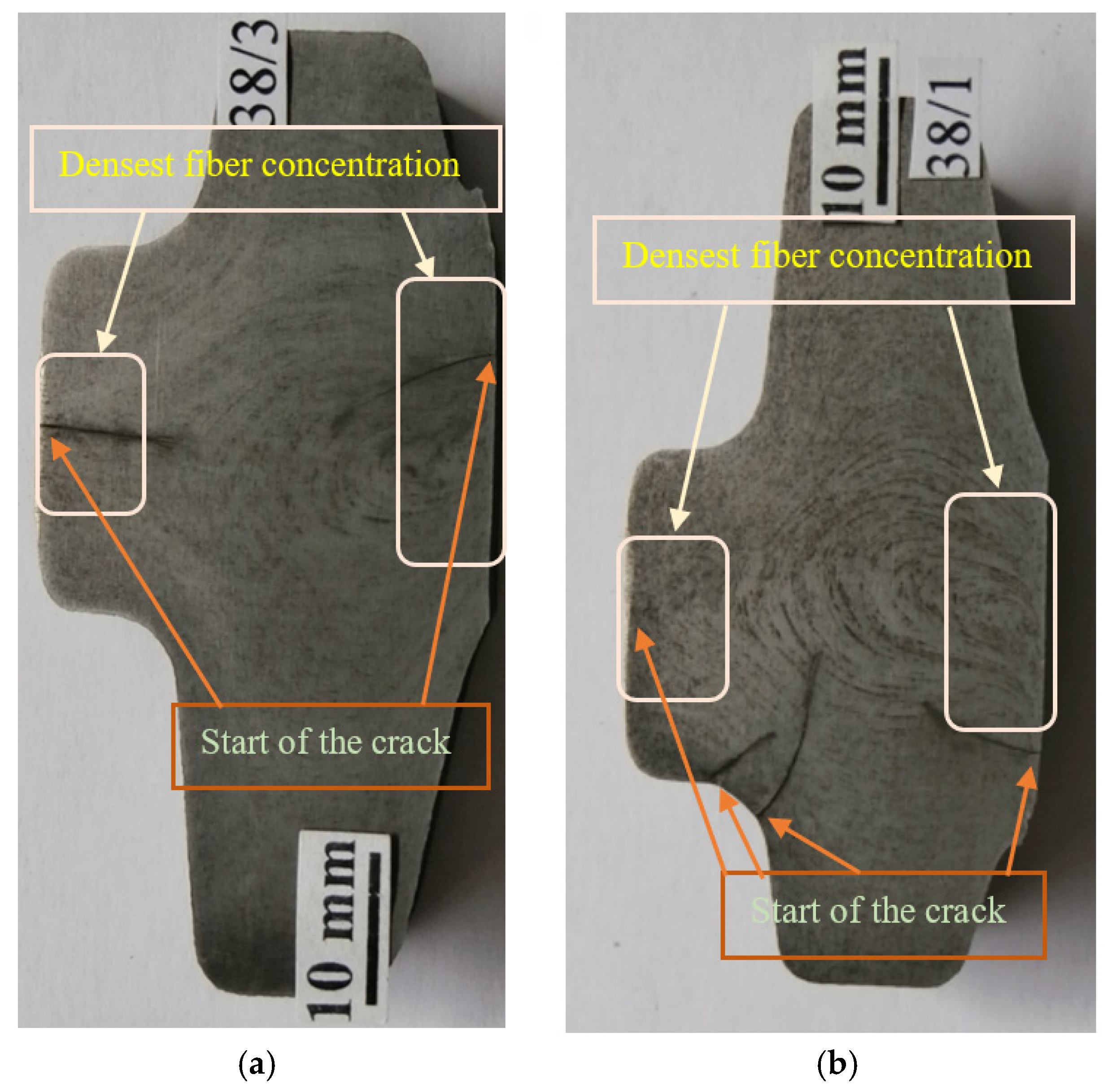
Macroscopic photograph of behavior fibers—deep etching: (a) location of cracks on forging from batch T21297; (b) location of cracks on forging from batch 63813.
Figure 6.
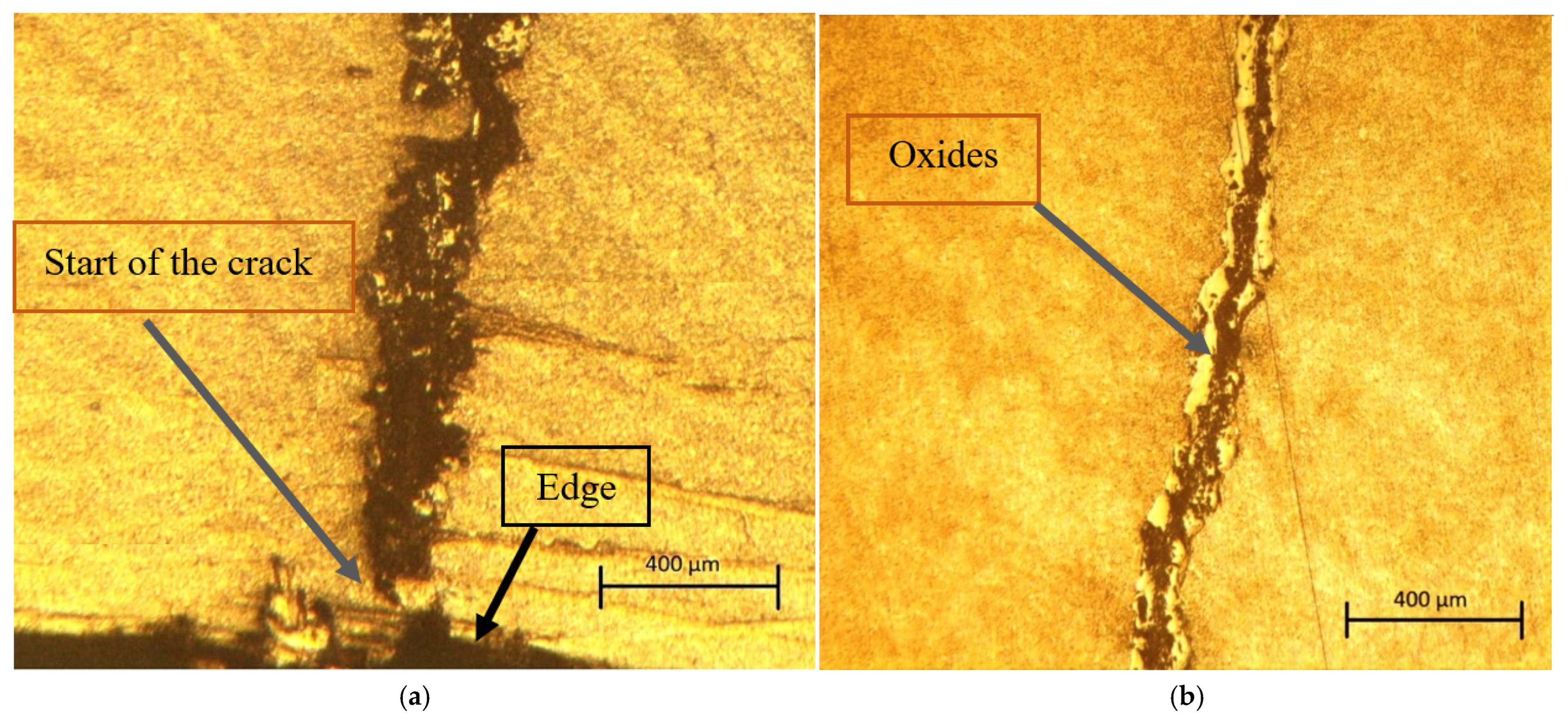
Macroscopic photograph of a crack (100× zoom). (a) Beginning of crack propagation at the edge of the forging. (b) Crack with a pronounced oxide layer.
Figure 7.
Hardness measurement points in the forging cross-section.
Figure 8.
Visual inspection of forging tools: (a) trimming plate and prominent radial crack; (b) die with crack and erosion.
Figure 9.
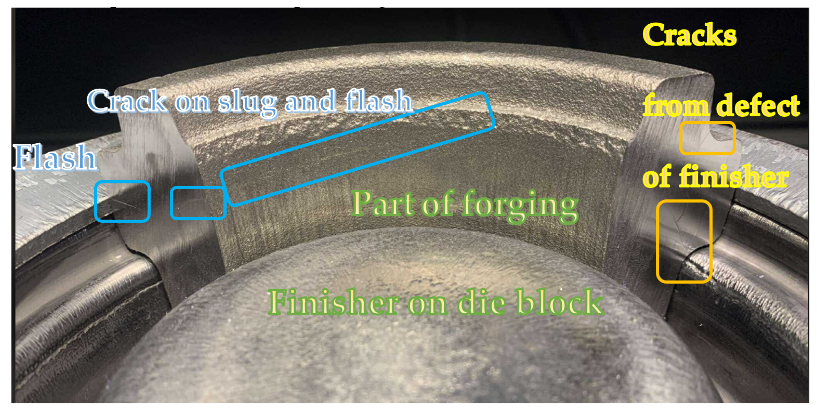
Part of the cross-section of the forging set in the die with the attached location of the flash.
Table 1.
Technology operations overview (explanations: N—normalizing annealing, Q—quenching, QT—quenching and tempering).
| Tech. Operation | Heating | Forging | Cooling | Heat Treatment |
|---|
| Open-Die | Closed-Die | Shearing and Punching | Normalizing Annealing | Quenching | Tempering |
|---|
| Machine | Induction furnace | Mechanical press 25,000 kN | Mechanical press 5000 kN | Belt conveyor | Continuous gas furnace | Continuous gas furnace | Continuous electric furnace |
| Material | Ø = 90 mm, h = 132 mm | Ø = 102 mm, h = 80 mm | Forging with flash and slug | Final forging; 42CrMo4 | 42CrMo4 + N | 42CrMo4 + N + Q | 42CrMo4 + N + QT |
| Working temperature | 1160–1220 °C | 1100–1160 °C | 1100–1160 °C | 950–1160 °C | 20–25 °C | 870 ± 10 °C; air cooling | 870 ± 10 °C; polymer cooling on 25 °C | 660 ± 10 °C |
Table 2.
Chemical analysis of individual batches (wt%, Fe balance).
| Chemical Element | Batch: 63813 (wt%) | Batch: T21297 (wt%) |
|---|
| C | 0.38 | 0.43 |
| Si | 0.22 | 0.29 |
| Mn | 0.80 | 0.75 |
| P | 0.013 | 0.011 |
| S | 0.010 | 0.003 |
| Cr | 1.10 | 1.14 |
| Mo | 0.214 | 0.203 |
| Al | 0.023 | 0.022 |
| Cu | 0.17 | 0.02 |
| V | 0.0044 | 0.004 |
| Ni | 0.17 | 0.03 |
Table 3.
Impact test results.
| Batch | KV + 20 °C (J) |
|---|
| Probe 1 | Probe 2 | Probe 3 |
|---|
| 63813 | 118.0 | 108.9 | 109.5 |
| T21297 | 111.2 | 110.7 | 105.0 |
Table 4.
Number of forgings from individual batches by type of non-destructive testing.
| Batch | Number of Forgings (pc) | Pieces with a Crack (pc) | Pieces with a Crack from Good Pieces (%) |
|---|
| VT Method | MT Method |
|---|
| 63813 | 534 | 212 | 381 | 71.34 |
| T21297 | 625 | 23 | 164 | 26.24 |
Table 5.
Crack parameters and direction in forging zones.
| Cracks Zones | Crack Parameter (mm) | Direction of Cracks |
|---|
| Depth | Length |
|---|
| I Flash area | 0–33 | 15–320 | To the center |
| II Slug area | 0–22 | 15–145 | To the center |
Table 6.
Calculating the cracking parameter PC.
| Chemical Composition | Batch 63813 | Batch T21297 |
|---|
| t | 30 mm | 30 mm |
| H | 1 ppm | 1 ppm |
| PC | 0.57% | 0.61% |
Table 7.
Measured hardness (HB) values in the cross-section of the forging.
| Line | 1 | 2 | 3 | 4 | 5 | 6 | 7 | 8 | 9 | 10 |
|---|
| A | 272 | 272 | 266 | 272 | 266 | 266 | 266 | 272 | 272 | 278 |
| B | 272 | 272 | 266 | 266 | 255 | 266 | 266 | 272 | 272 | 278 |
| C | - | - | - | 272 | 272 | 272 | - | - | - | - |
| Disclaimer/Publisher’s Note: The statements, opinions and data contained in all publications are solely those of the individual author(s) and contributor(s) and not of MDPI and/or the editor(s). MDPI and/or the editor(s) disclaim responsibility for any injury to people or property resulting from any ideas, methods, instructions or products referred to in the content. |
© 2025 by the authors. Licensee MDPI, Basel, Switzerland. This article is an open access article distributed under the terms and conditions of the Creative Commons Attribution (CC BY) license (https://creativecommons.org/licenses/by/4.0/).

