Article

Harnessing Industrial Waste for Sustainable Arsenic in a Mine Leachate Treatment

1
Department of Materials Science and Metallurgical Engineering, University of Oviedo, 33003 Oviedo, Spain
2
Department of Mining Exploitation and Prospecting, School of Mining, Energy and Materials Engineering, University of Oviedo, C/Independencia 13, 33004 Oviedo, Spain
*
Author to whom correspondence should be addressed.
Metals 2025, 15(8), 888; https://doi.org/10.3390/met15080888
Submission received: 22 June 2025 / Revised: 27 July 2025 / Accepted: 28 July 2025 / Published: 8 August 2025

Abstract

This study focuses on the removal of arsenic (As) from contaminated water originating from an abandoned mercury mine landfill. To obtain results that more accurately reflect the material’s behavior under real-world conditions, tests were conducted starting with agitation, followed by column tests, and subsequently channel tests. The results demonstrated high efficacy of industrial waste materials (FA, HA, and EA) in adsorbing As, with a significant reduction of this contaminant in the leachates. Practical applications of this methodology include its potential use in large-scale remediation projects, improving water quality in mining-affected areas, and contributing to sustainable waste management practices.

1. Introduction

The use of natural resources has surged by 70% since 1970 and is projected to keep rising with population and economic growth. This increased resource use and its environmental impact threaten air and water quality, hindering sustainable development. To achieve climate neutrality by 2050, the European Union has introduced the European Green Deal, a strategy for a climate-neutral, resource-efficient, and competitive economy.
To minimize natural resource depletion, we must start recycling and reusing, on a large scale, the ‘waste’ generated in industrial processes and daily life, as this waste can become another source of resources. Circularity and the recycling of raw materials from low-carbon technologies are an integral part of the transition to a climate-neutral economy.
Mining has constituted a fundamental economic activity throughout history, providing the mineral resources indispensable for industrial and technological advancement. However, this activity has also resulted in a considerable impact on the environment, leading to the creation of extensive areas of degraded and contaminated land. It is of paramount importance to restore these mining areas in order to mitigate the negative environmental impacts and promote sustainability.
In this context, the utilization of industrial waste for the restoration of degraded mining sites is presented as an innovative and sustainable solution. Industrial waste, which is often regarded as waste, can be effectively reused to rehabilitate land affected by mining. This practice not only contributes to environmental remediation but also offers a viable alternative for industrial waste management, reducing the necessity for landfills and minimizing the environmental impact associated with their disposal.
Fly ash (FA) is the principal industrial waste byproduct from the burning of solid fuels. The steel industry generates a large amount of waste in the production of steel: blast furnace slag (HA) and iron and steel slag (EA). All these wastes have been extensively utilized as substitute raw materials in the construction and cement industries [1,2].
Arsenic is a chemical element that naturally occurs in soil and rocks. It can find its way into the atmosphere through a number of natural sources, from volcanic eruptions to disturbing wind-blown dust. Still, human activity is also responsible for its release. There have been many efforts to estimate global atmospheric arsenic sources; for example, coal burning, manufacture of semi-conductive electronics, and other electronic component products, including electrical components, industrial nonferrous metal mining and smelting processes, and various metallurgical processes [3,4].
Arsenic can be leached from soil, minerals, and industrial rubbish that may emanate from mining or metallurgical operations into water. pH and redox potential have an important effect on adsorption/desorption and precipitation/dissolution processes, thereby determining the mobility of arsenic.
Rieuwerts et al. [5] conducted a study to investigate the role of mineralogy in the mobility and environmental impact of arsenic in mining waste and river sediments. Under reducing conditions, As(III) is the major stable species found in natural waters, and, under oxidizing conditions, it is more commonly As(V). In addition, As(III) is more toxic than As(V). Despite being a natural component of the Earth’s crust, arsenic concentrations in surface and ground waters are typically as low as 1 μg/L or less but can exceed one milligram per liter in highly contaminated soil. The released arsenic is typically associated with very small particles [6,7].
Various methods for arsenic removal include coagulation–flocculation, ion exchange, membrane processes, and adsorption. However, coagulation–flocculation is ineffective for As(III), and ion exchange is influenced by competing ions, making it unsuitable for As(III) removal [8,9].
The adsorption method is gaining attention due to its high efficiency, simplicity, potential for regeneration, and cost-effectiveness. The mineralogical composition of steel slag includes minerals like magnetite, hematite, and silicates, which have a high affinity for heavy metals and other contaminants. These minerals provide active sites for adsorption and complexation [10,11].
Arsenic adsorption by steel slags has received attention due to their potential as low-cost adsorbents in environmental remediation [12,13]. Steel slag, especially when combined with other materials, demonstrates significant arsenic removal efficiencies through various mechanisms, such as adsorption, precipitation, and passivation [14,15]. Steel slag can achieve arsenic removal efficiencies of up to 95% under synthetic water conditions [11]. This study found that both As(III) and As(V) exhibit similar removal mechanisms in the presence of calcium, with As(V) generally being removed more efficiently than As(III) when using adsorbents containing calcium or iron.
Fly ash, a by-product of coal combustion in power plants, has been widely studied for its potential as a heavy metal adsorbent due to its unique properties and abundance. The adsorption of heavy metals on fly ash occurs through several mechanisms, such as ion exchange, complexation, and surface precipitation [16,17].
Fly ash is mainly composed of silica (SiO2), alumina (Al2O3), iron oxide (Fe2O3), and unburned carbon. These components provide active sites for heavy metal adsorption. The high content of Al2O3 and SiO2 makes them particularly suitable for heavy metal adsorption, and the presence of unburned carbon increases their adsorption capacity by providing additional surface area and active sites [18]. Fly ash has shown high adsorption capacities for various heavy metals. For instance, it can achieve adsorption of lead ions at 18 mg/g, copper ions at 7 mg/g, and humic acid at 36 mg/g [19]. Using fly ash as an adsorbent helps in the valorization of waste material, reducing its environmental impact. This is particularly beneficial compared to methods that generate additional waste or require the use of non-renewable resources.
The adsorption process involves the formation of Fe–As complexes and calcium hydroxyarsenate, enhancing arsenic capture [20,21].
The purpose of the water treatment system is to reduce as far as possible the concentration of arsenic in the water by using by-products from industry, such as coal-burning power plant ashes and steel slags.
A previous study evaluated the efficacy of four distinct industrial waste materials derived from steelmaking processes and thermal power plants in the removal of arsenic and other toxic elements from leachate [22]. The leachates in question originate from the tailings of an abandoned mercury mine, thereby underscoring the environmental concerns associated with such sites. This study revealed that the removal of arsenic occurs rapidly within the initial minutes of treatment, with the removal efficiency increasing over time to reach equilibrium after approximately eight hours. This suggests that the process is not only effective but also relatively rapid.
It is crucial to transition from dynamic leaching tests, which are conducted in laboratory settings, to column and channel tests to obtain results that more accurately reflect the behavior of the material under real-world conditions.
These tests more effectively simulate liquid flow and the interaction between the material and the leachate, thus allowing the extraction efficiency and kinetics of the process to be evaluated. Furthermore, these tests provide invaluable data on the required amounts of reagents and optimal contact time, which are crucial for the successful implementation of the process in the field.

2. Materials and Methods

2.1. Materials

Three industrial by-products/wastes were investigated as potential adsorbents: blast furnace slag (HA), supplied by EDERSA, coal fly ash (FA) (supplied by EDP), and steel mill slag (EA), supplied by Arcelor Mittal.
The chemical composition of the by-products used in the column test was analyzed using X-ray fluorescence (Phillips PW2404, Malvern Panalytical, Enschede, The Netherlands) to determine the major elements, while the quantification of the trace elements was performed by mass spectrometry with inductively coupled plasma (ICP-MS Agilent 7700, Agilent Technologies, Santa Clara, CA, USA) prior to dissolution with aqua regia using an Anton Paar 3000 microwave system (Graz, Austria), as shown in Table 1. The by-products for the microchannel test included the same FA fly ash as in the previous test, along with a different HA blast furnace slag provided by Edersa. While the major elements are similar to the previously used HA, this batch has a lower arsenic content, measuring 1.05 mg/kg.
X-ray diffraction (XRD) analysis was conducted to determine the mineralogical composition of the byproducts, using a PANalytical X′Pert Pro MPD diffractometer (Malvern Panalytical, Enschede, The Netherlands) equipped with CuKα radiation. The instrument operated at 45 kV and 40 mA, scanning over a 2θ range from 5° to 90° at a rate of 1° min−1. X-ray diffraction (XRD) analysis revealed that the primary crystalline phases in the FA were Mullite (Al6Si2O13) and Quartz (SiO2), with minor phases including Maghemite (γ-Fe2O3). Regarding the slag materials, the EA slag was mainly composed of Akermanite (Ca2Mg(Si2O7)) and Larnite (Ca2SiO4), with Gypsum and Srebrodolskite (Ca2Fe2O5) as secondary phases. The presence of Calcite, Hematite (α-Fe2O3), and Sillimanite (Al2SiO5) was also inferred. In contrast, the HA slag exhibited a more complex mineralogy, with dominant phases including Calcite, Srebrodolskite, Larnite, Akermanite, Merwinite (Ca3Mg(SiO4)2), and Magnetite (Fe3O4). The minor phases identified were Lime (CaO) and Portlandite (Ca(OH)2), with possible traces of Quartz and Wüstite (FeO) [22].
Water was taken from the Soterraña mine and analyzed for arsenic and mercury by inductively coupled plasma spectroscopy (ICP-MS). The mine water used in these experiments had an arsenic concentration of 12,382 μg/L and 12,472 µg/L for the column and channel tests, respectively, while the mercury concentration was below the detection threshold of the analytical technique, 0.2 µg/L. For this reason, only the removal of arsenic from the contaminated water will be taken into account in the tests.

2.2. Methods

2.2.1. Columns

The fly ash was used without any prior treatment, while the slags were sieved. The blast furnace slag had a particle size range of 1–2 mm, whereas the steel mill slag had a particle size range of 2–4 mm for the base and 1–2 mm for the column filler.
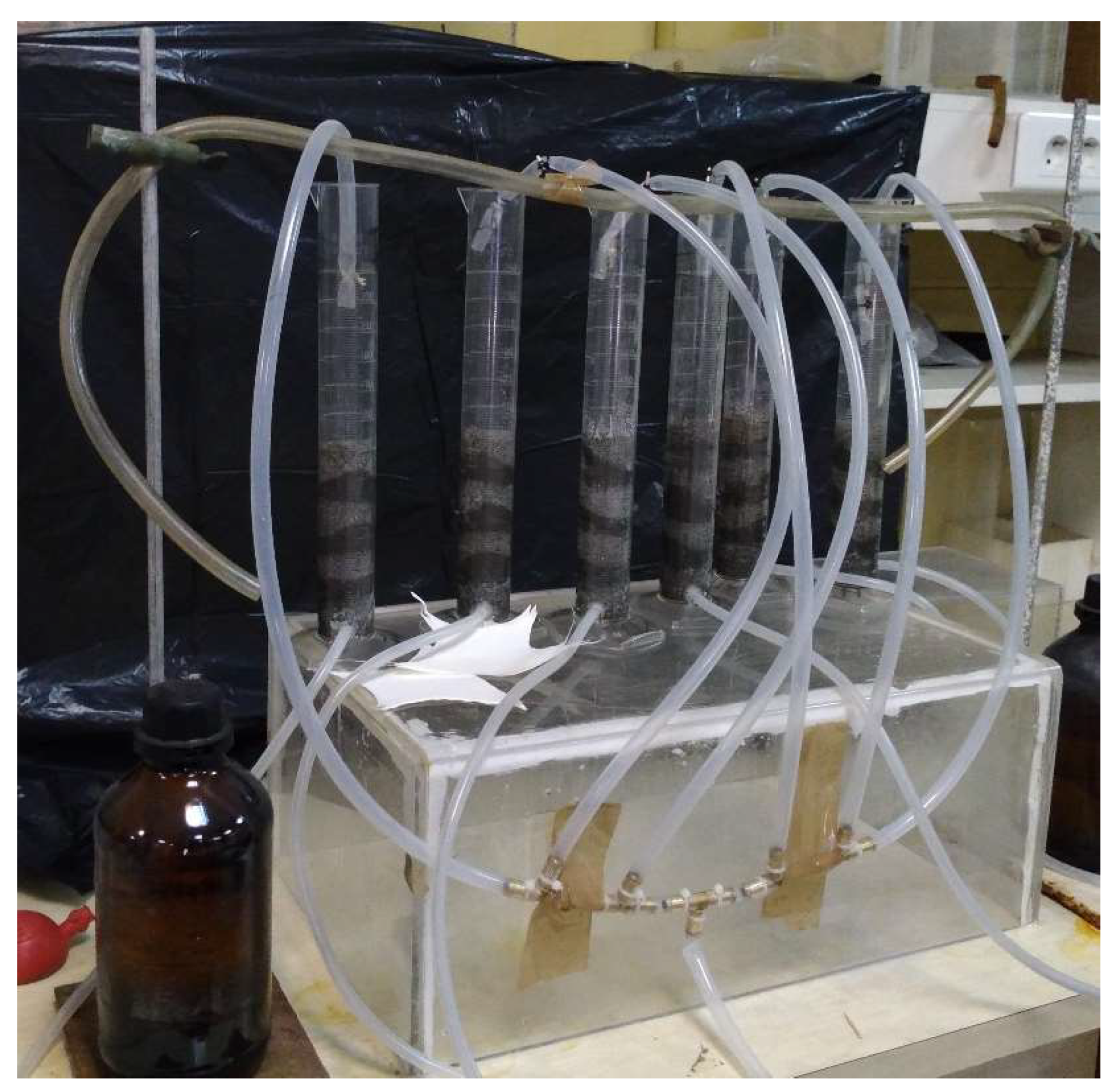
A total of six columns, with a diameter of 3 cm, were constructed and filled with a total of seven layers of material. Previous investigations involving fly ash have demonstrated that optimizing liquid percolation and enhancing liquid–solid mass transfer can be achieved by stratifying fine-grained fly ash with interlayers of coarser granular media. This layered configuration increases the system’s hydraulic conductivity and promotes more efficient leachate drainage and contaminant transport control.
The material was distributed in three different ways, resulting in two columns of each distribution. In all columns, a layer of 40 g of steel slag was initiated as a base, and distinct layers of by-products were deposited on top of it.
The initial two columns, IA and IB, were filled with alternating layers of 15 g of fly ash and 30 g of blast furnace slag (Figure 1). The total volume of material in each column was 175 g (45 g FA+ 90 g HA + 40 g EA).
Similarly, columns IIA and IIB were filled with a total of 175 g (45 g FA + 60 g HA + 70 g EA).
The final two columns, IIIA and IIIB, were also filled with 175 g of by-products, but in this instance, only 45 g of FA and 130 g of EA were used.
The water was pumped through the top of the column in such a way that it allowed percolation through the material. The test lasted approximately one month, with water pumped into the columns for eight hours per day.
At the end of the column, a device was installed to collect the water at four-hour intervals for subsequent ICP analysis. The volumes of water passing through each column during the four-hour period were quantified (Figure 2).
After the test concluded, the columns were dismantled, and the adsorbent material was dried. The various by-products were then separated through sieving, ground, and analyzed using inductively coupled plasma spectroscopy (ICP).

2.2.2. Microchannels

On the other hand, scaled microchannels were built, too. The by-products, FA without pre-treatment, and HA slag with a particle size of 1 cm, were used to make the microchannels.
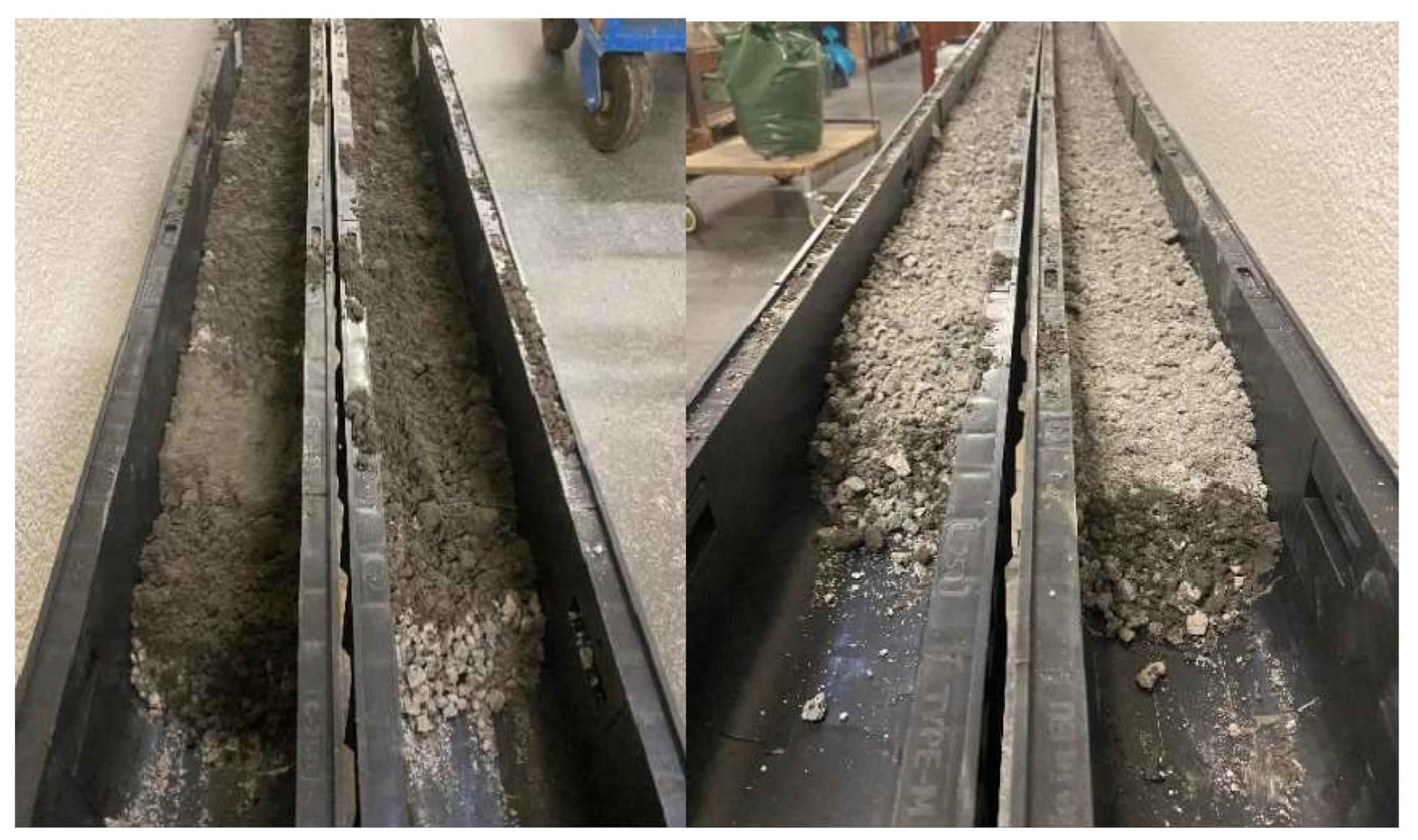
Microchannels are channels at a reduced scale compared to real ones that can be easily implemented in the laboratory (e.g., in our case, E = 1:10 approximately). The system was similar to reality, so the characteristic parameters (channel slope, by-product granulometry, water flow, etc.) were also scaled up. Two 3 m channels were built, each consisting of three coupled channels 1 m long, 14 cm wide, and 13.4 cm high. (Figure 3).
The microchannels were filled with a total of eight distinct layers of material. The initial layer consisted of blast furnace slag (HA), overlaid with a 0.5 cm layer of fly ash (FA). This sequence was repeated on four occasions, generating a total height of 6 cm.
A total of 39 kg of fill material was used in each microchannel: 23.5 kg of HA and 15.5 kg of FA.
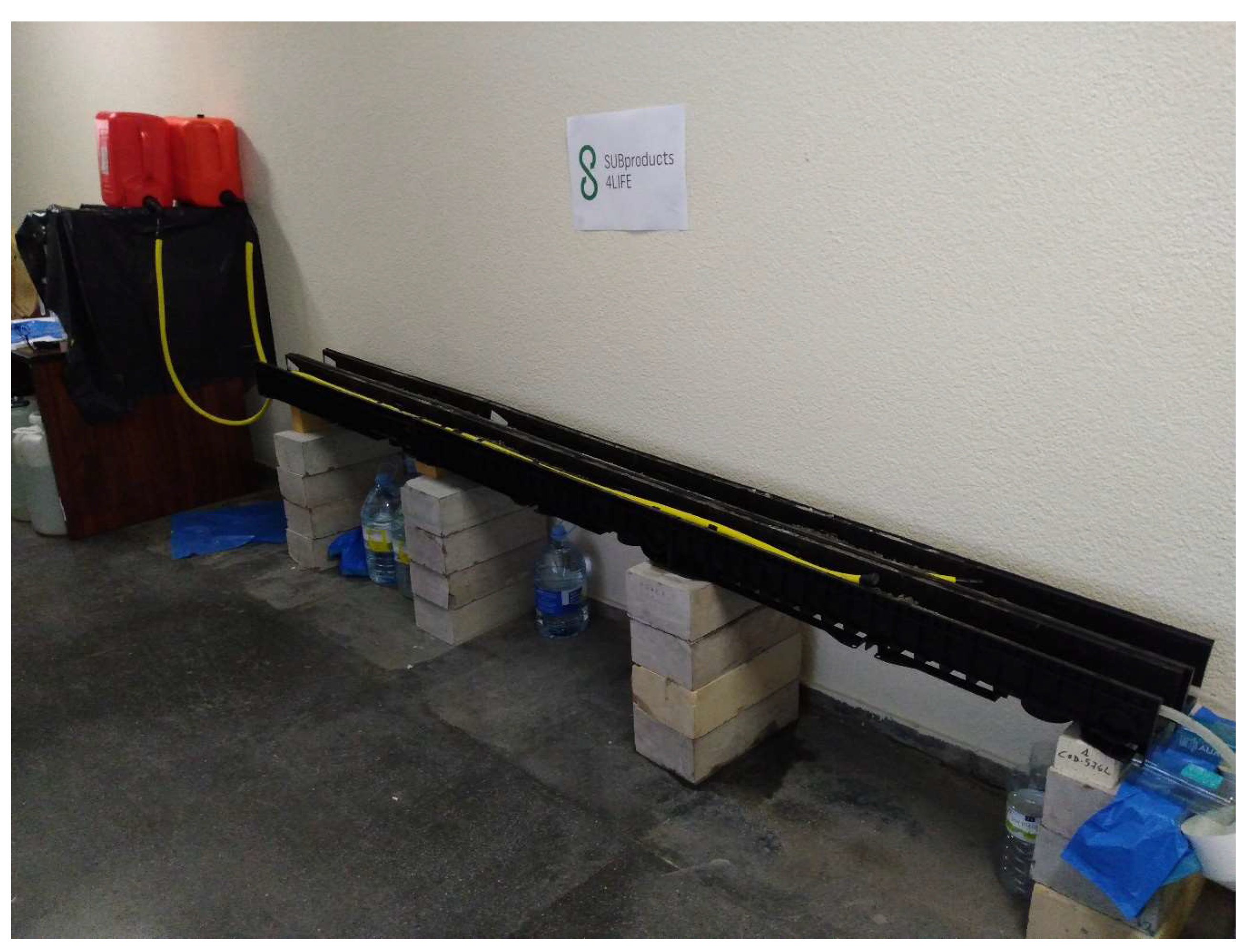
The system for supplying the water was a hose with perforations distributed along its entire length, similar to drip irrigation. The microchannels are then fed with a flow of water from elevated tanks at a certain height, so water descends by gravity. This configuration facilitated the generation of a uniform and consistent flow along the length of the microchannel. (Figure 4).
The mean flow of contaminated water through the microchannel was minimal, with an average of 0.17 L/h (0.0028 L/min). The entire test period lasted slightly over a week, during which time a total volume of 29.5 L of water flowed through the microchannel.
At the conclusion of the test, samples of the adsorbent material were collected at 50 cm intervals along the entire length of the microchannel. After drying, HA and FA were separated by sieving and then analyzed using ICP.

3. Results and Discussions

3.1. Test Columns

After one month of testing, the volume of mine water passing through the IA and IB columns was approximately 4 L (3.995 L for IA and 4.050 L for IB). With regard to columns IIA and IIB, there is a discernible variation in the water flow rate, with 4.445 L recorded for IIA and 6.164 L for IIB. The flow rate for the columns utilizing FA and EA is 4.043 L for IIIA and 4.636 L for IIIB.
The difference between the inlet and outlet concentrations of the columns, together with the volume of treated water, permits the calculation of the mass of arsenic removed from the water after passing through the columns.
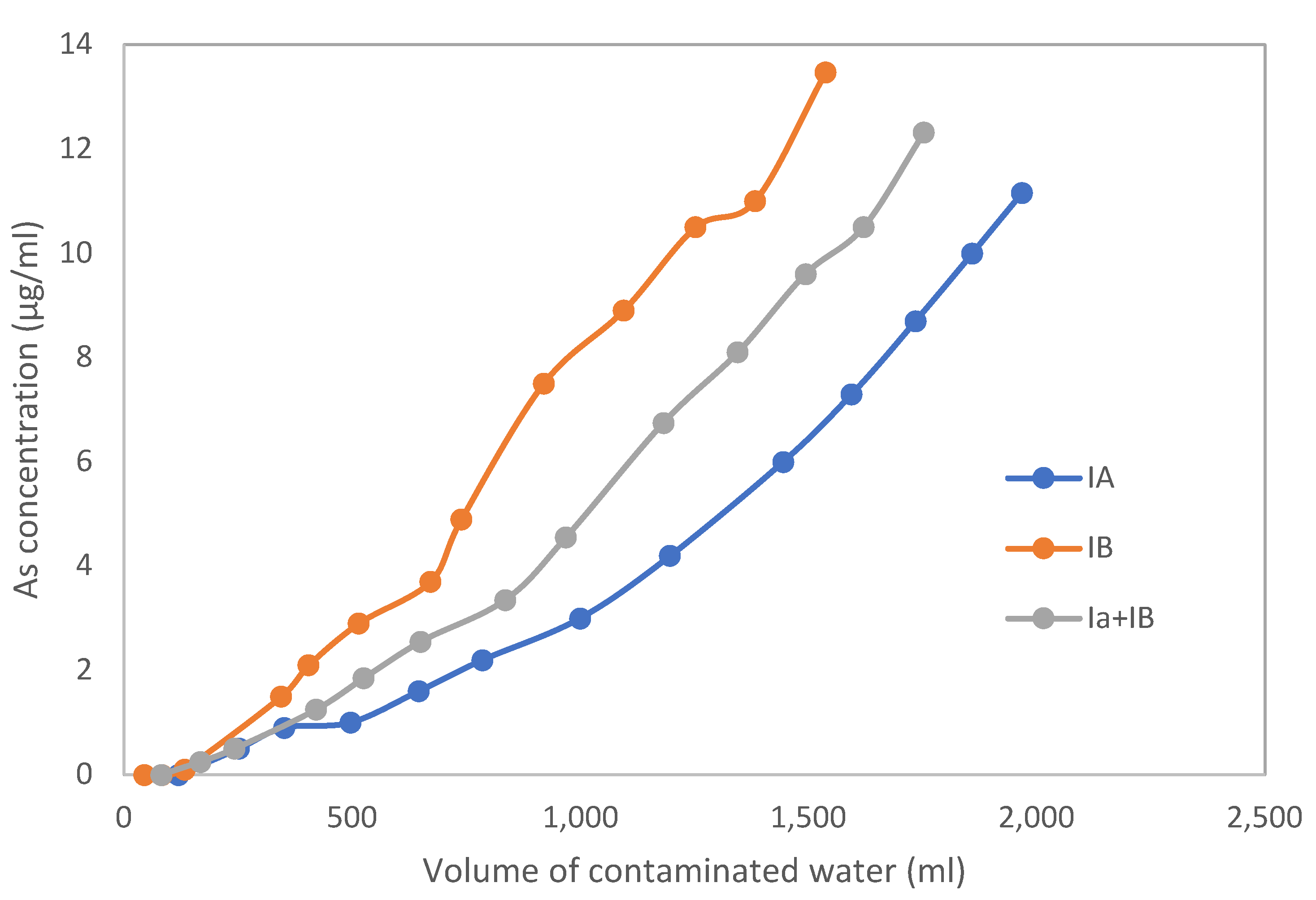
Figure 5 shows the As concentration of the mine water at the outlet of columns IA and IB in the first 14 days of the test. The retention of arsenic is highly effective, approaching 100%, as the concentration at the entrance of the columns was 12,382 μg/L and the concentration at the exit was 11 or 13 μg/L, values below the permitted legal limit. Figure 5 also shows the average of the two columns (IA + IB).
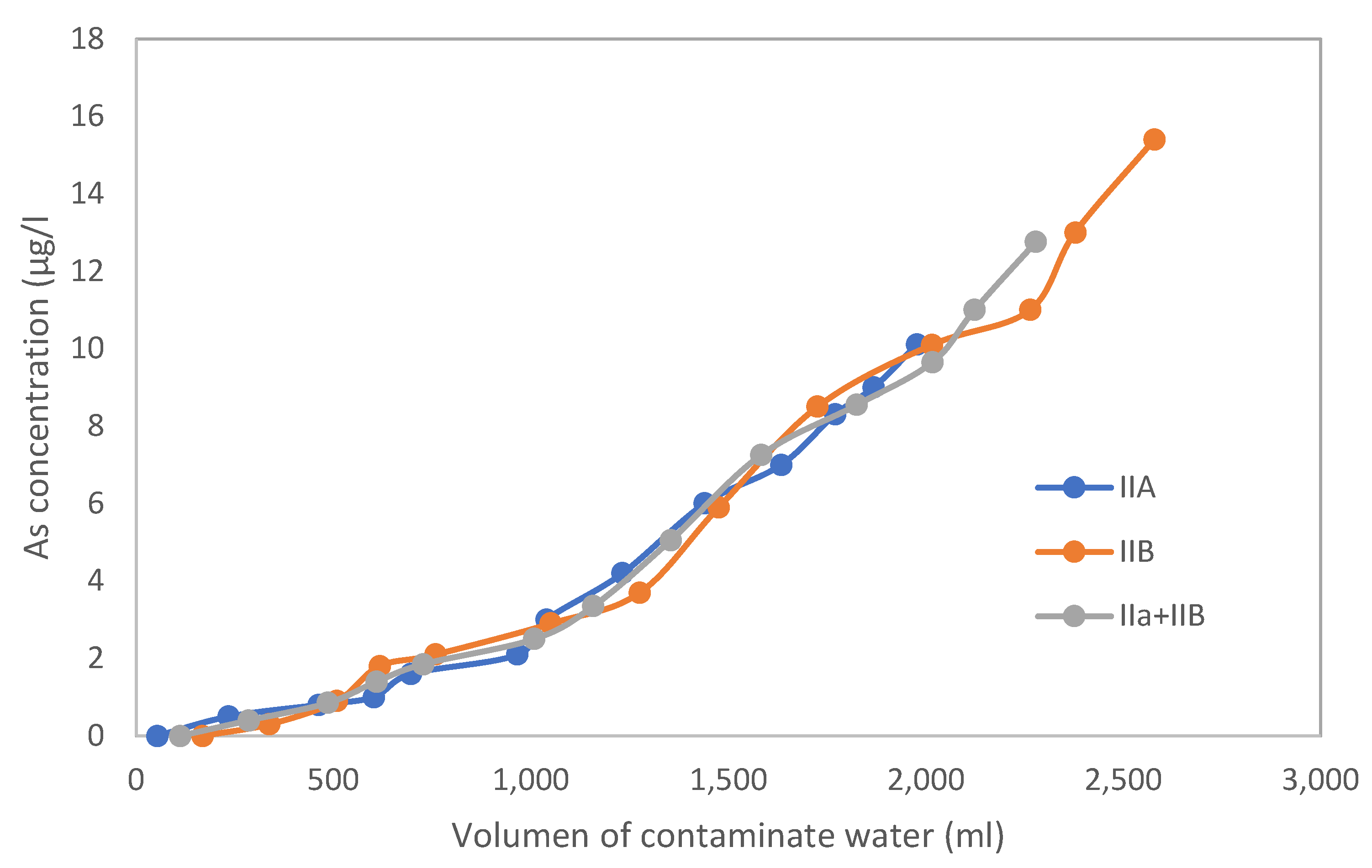
In column II, where one of the ash layers has been replaced by blast furnace slag, it can be observed that the results of the two columns are very similar in the first 14 days of the test. In this period of time, recovery values of almost 100% are reached, as in the previous case. The remaining concentration of contaminants in the outlet water is between 10 and 15 μg/L (Figure 6).
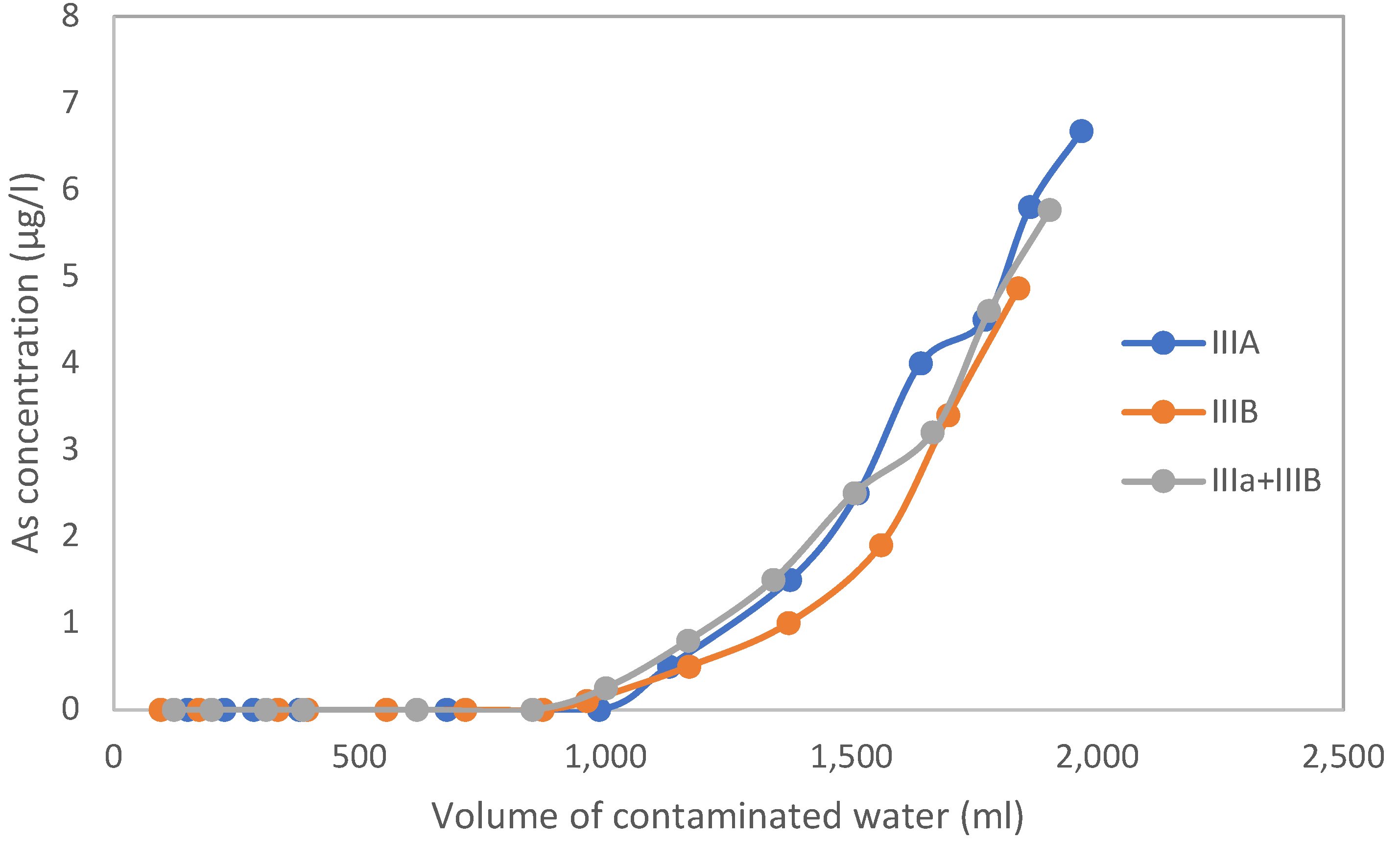
The two columns, composed of FA and EA (IIIA and IIIB), exhibit very similar behavior, characterized by a pronounced decrease in concentration, as shown in Figure 7. The concentration of contaminants in the water sample decreased from 12,382 µg/L to a range of from 6.8 to 4.9 µg/L, representing a reduction of nearly 100%.
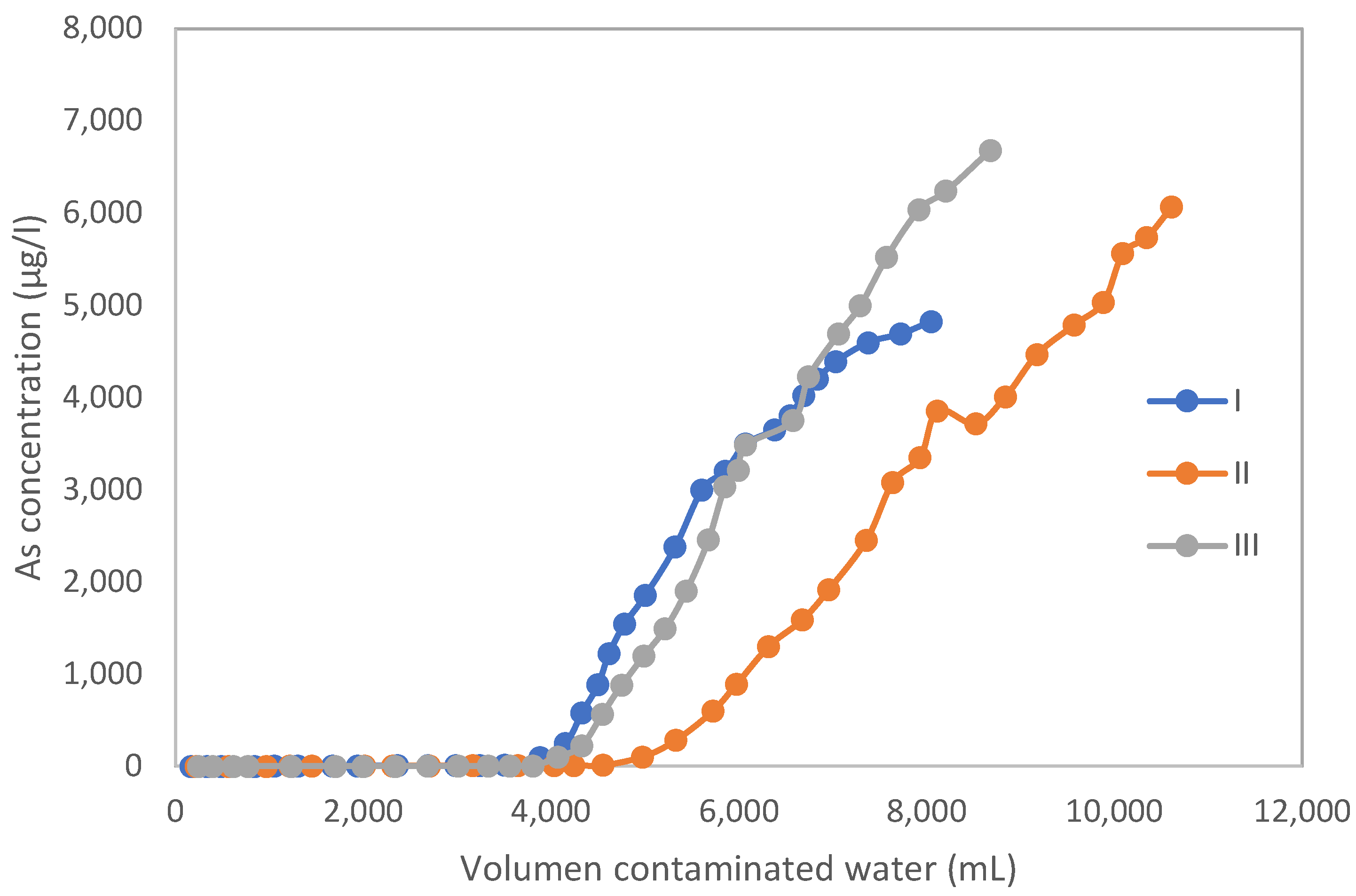
A comparison of the three types of columns reveals a very similar behavior, although the ash and steel slag column exhibits the lowest As values at the end of the days analyzed. In light of the preliminary findings, a decision was taken to consolidate the water samples from the columns with identical compositions, resulting in a reduction of the number of samples analyzed per day to three. Each sample represented a specific column: column I, column II, and column III.
Figure 8 displays the arsenic concentrations in the water exiting the columns throughout the entire month of treatment. After the initial four liters, almost complete arsenic removal is achieved in all cases. As the volume of mine water treated increases, some of the active sites are already occupied by As, resulting in incomplete removal.
The total amount of arsenic (As) introduced into the columns throughout the entire test was calculated, as well as the amount of As retained by the by-products.
Column I, consisting of 175 g (45 g of FA + 90 g of HA + 40 g of EA), received a total of 99,662 μg of As at the passage of the contaminated water and retained 86,721 μg, representing an 87.02% removal of As from the contaminated water.
In the case of column II, composed of 175 g (45 g FA + 60 g HA +70 g EA), the amount of As contributed by the contaminated water during the test was 131,360 μg, while the amount retained by the by-products in the test was 113.676 μg. This yields an As retention percentage of 86.5%.
The final calculation revealed that the amount of As introduced into column III, consisting of 175 g (45 g FA + 130 g EA), was 107,463 μg. The retention of this by the column was 90,345 μg, representing an As retention percentage of 84.1%. If the maximum admissible concentration of arsenic in water is 50 µg/L, waters with contamination as high as 30,000 µg/L (La Soterraña) would necessitate a reduction of 99.83%.
The mine leachate exhibited a slightly acidic pH of 5.2, which increased upon contact with various waste materials, reaching values as high as 9.1 in certain cases. This behavior can be attributed to the elevated content of alkaline earth metals, when these by-products come into contact with the slightly acidic mine leachate, partial dissolution of these metal oxides occurs, and these reactions consume hydrogen ions, thereby increasing the pH of the leachate. As a result, the leachate pH can rise significantly, often reaching values above 9, depending on the composition and reactivity of the by-products.
Based on the Eh-pH diagrams of the As–O–H system, HAsO42− is the dominant arsenic species within the pH range of from 7 to 10, which corresponds to the conditions achieved following treatment with the various byproducts [23].
Numerous studies have proposed mechanisms for arsenic removal from aqueous solutions, primarily involving adsorption and precipitation processes. Adsorption occurs both on the external surfaces and within the pore structures of iron and aluminum oxides and hydroxides. Additionally, arsenic can be removed through the precipitation of calcium arsenate compounds and mixed calcium–iron arsenate (Ca–Fe–AsO4) phases [24,25,26,27].
In a previous study, Ayala et al. [22] employed energy-dispersive X-ray spectroscopy (EDX) to investigate the dominant arsenic removal pathways associated with different waste materials. The findings indicated that, in electric arc furnace (EA) slag, arsenic is primarily removed via the formation of calcium–arsenic compounds. Conversely, in blast furnace slag (HA) and fly ash (FA), arsenic removal is likely governed by adsorption onto iron-bearing phases or by the precipitation of calcium–arsenic species.
The data obtained corroborate the results obtained in the previous article carried out with the same materials, but with agitation [22]. That work showed that the remediation of arsenic-contaminated water is feasible through the application of an appropriate treatment process. Batch adsorption experiments typically yield higher metal adsorption capacities compared to continuous flow column systems. This is primarily due to the longer contact time between the adsorbate and adsorbent in batch setups, which allows for more complete utilization of active sites before equilibrium is reached [28,29].
Following the conclusion of the testing process, the blast furnace ash and slag samples obtained from the columns were subjected to analysis by ICP, as shown in Table 2.
The results for the FA showed an arsenic (As) concentration of 1228.7 mg/kg, representing an increase of 1169.7 mg/kg As by the end of the test. This indicates that 0.135 kg of this by-product captured 157.9 mg As from the mine water. Over 55% of the As was retained by FA, 20% by EA, and 24% by HA. The lower As retention by slags, despite using a larger quantity of these by-products, can be attributed to the different particle sizes of the adsorbents. FA is a very fine powder, providing a large contact surface between the solid and the mine water. In contrast, HA has a particle size of 1–2 mm, and for EA, half of the particles are 2–4 mm, and the other half are 1–2 mm.
In the initial stage of column operation, when mine water is introduced, arsenic (As) adsorption predominantly occurs near the column inlet. This is due to the abundance of unoccupied active sites on the adsorbent, which readily bind incoming arsenic ions. As the mine water continues to flow through the column, these active sites gradually become saturated. Over time, the adsorbent’s capacity diminishes, leading to an increase in arsenic concentration in the effluent. Consequently, the adsorption efficiency decreases along the column’s length, resulting in higher arsenic accumulation in the upper layers compared to the lower ones. This spatial distribution reflects the progressive saturation of the adsorbent and the dynamic nature of contaminant transport within the column [30,31].
Once the test was completed, the columns were dismantled, and the adsorbent material was dried. The different by-products were then separated by sieving, as they have very different particle sizes. Once all the FA layers had been mixed, they were homogenized and ground, and the same was performed for HA and EA. Finally, they were analyzed using inductively coupled plasma spectroscopy (ICP).
In order to achieve optimal results, it is essential to ensure that the flow of water in contact with the by-products is properly regulated, thereby facilitating effective interaction between the water and the solid material capable of retaining the As.
Recent studies have demonstrated the high efficiency of adsorption columns in removing arsenic and other heavy metals from contaminated water, with particular emphasis on the optimization of operational parameters to enhance treatment performance. Mojiri et al. [32] demonstrated that variables such as flow rate, bed depth, pH, initial arsenic concentration, and the presence of competing ions significantly influence the efficiency of fixed-bed systems. These parameters directly affect mass transfer dynamics and the availability of active adsorption sites. Complementary to this, Litynska et al. [33] highlighted the importance of adsorbent characteristics—particularly surface area, pore structure, and the oxidation state of arsenic—when using nanostructured materials. These insights reinforce the notion that both hydraulic design and adsorbent physicochemical properties must be carefully optimized to achieve consistent and high removal efficiencies. The present results support this view, suggesting that tailoring column operation to site-specific water chemistry and material properties is essential for effective contaminant mitigation.
The ability of the columns to remove As decreases as As is captured and retained by the active sites, resulting in clogging. Consequently, it is advised that water treated with a concentration greater than the maximum permitted by legislation undergo an additional filtration process to reduce the final As content.

3.2. Microchannels

The test had two parts. In the initial phase of the experiment, the system was exposed to contaminated water in both channels. In the next phase, two channels were prepared: one replicated the previous test to study its repeatability, while the second used one of the contaminated channels from the first test and was supplied with distilled water as before. The aim was to simulate the impact of precipitation and determine if it could leach arsenic (As) retained by the by-products. The period of each test lasted slightly over a week, during which a total volume of 29.5 L of water was circulated through the microchannel. With these parameters, a residence time of well over two hours was assured.
The results of the second test showed minimal variation from the first test in the channel subjected to contaminated water, so no further analysis was conducted. Analyses of the water leaving the channel supplied with distilled water showed no arsenic, indicating that rainwater would not release arsenic.
Since all the water in question had the same origin, only one ICP analysis was performed on the water at the inlet of the canal. The analysis demonstrated an arsenic concentration of 12,472 µg/L, while the mercury content was below the detection limit of the employed analytical technique. To assess the As and Hg concentrations, water samples were collected at the canal outlet at six distinct time points throughout the test. The differences in concentration, along with the volume of treated water, were used to calculate the mass of pollutants released from the water.
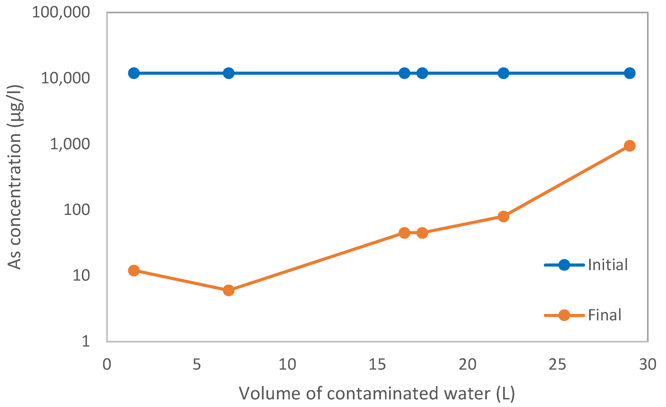
Figure 9 shows the evolution of the arsenic (As) concentration in the water at the inlet and outlet of the microchannel. In view of the pronounced decrease in concentration, a logarithmic scale has been employed on the ordinate axis. Given the considerable ratio of adsorbent mass to volume, the reduction in concentration is pronounced. However, it is notable that the water undergoes a transition from a concentration exceeding 10,000 µg/L to a concentration within the range of from 10 to 1000 µg/L, with a reduction of between 90% and 99.9%.
As can be seen in Table 3, in average values, the concentration of arsenic in the water samples decreased from 12,472 µg/L at the inlet to 147 µg/L at the outlet, representing an average reduction of 98.8%.
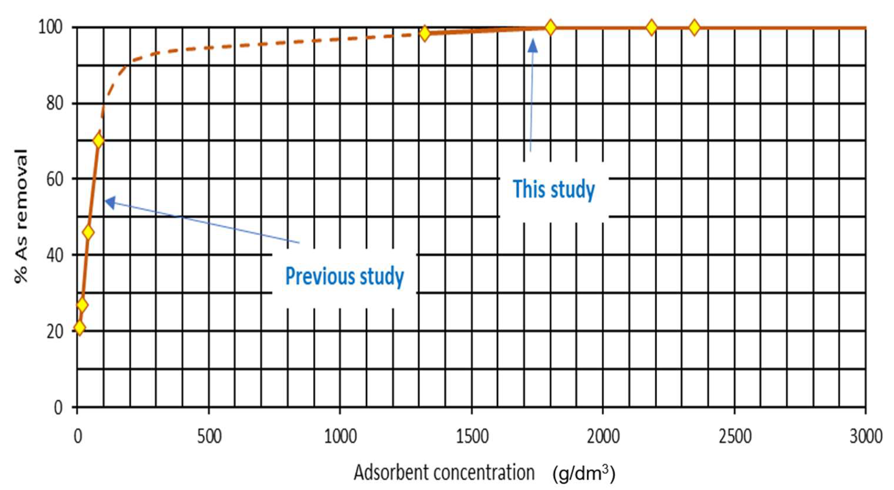
A comparison can be made for the whole range of adsorbent concentrations employed in the test, with the volume of treated water increasing in tandem. The reduction is plotted as a function of dosage in Figure 10.
Furthermore, the curve obtained in this test can be compared with the curve obtained in the laboratory [22], and an extrapolation of the curve between these two sections can be made.
At the end of the test, samples of the solid material (ash + slag) were taken every 50 cm. The slag was separated from the ash, and the concentrations of arsenic were analyzed by ICP (Figure 11). It was observed that the arsenic (As) concentration in both by-products increased along the length of the channel as the amount of treated water increased. This was due to water being supplied from a perforated hose, similar to drip irrigation, and also flowing down the inside of the microchannel. Arsenic retention was higher for FA than for HA, attributed to the different granulometry of the by-products.
The variation in As concentration, together with the mass of the material, allows estimation of the amount of contaminant retained, which should be of the same order as that discharged by the contaminated water, as shown in Table 4.
The analysis of the FA samples obtained following the conclusion of the test demonstrated that the average concentration reached 71.46 mg/kg. The ashes used in the laboratory had an initial arsenic concentration of 59 mg/kg. Therefore, approximately 193.13 mg of arsenic were retained, which is 54.4% of the As removed.

4. Conclusions

The experiments conducted at the Metallurgy Laboratory of the University of Oviedo, building upon previous research and serving as a precursor to in situ implementation, successfully demonstrated the effectiveness of the proposed methodology and met this study’s objectives. Column percolation tests revealed that the incorporation of steel slag and fly ash significantly enhanced arsenic adsorption from wastewater. In contrast, batch adsorption experiments from earlier phases showed higher arsenic uptake capacities than continuous flow column systems. This difference is attributed to the prolonged contact time and the fine particle size of FA, HA, and EA, which facilitated greater solid–liquid interaction and more complete utilization of active sites before equilibrium was reached. Among the tested materials, fly ash emerged as the most effective adsorbent due to its favorable chemical composition and surface characteristics. Further research aims to further optimize fly ash performance and broaden its application in environmental remediation. Additionally, the use of static channels, which increased the quantity of adsorbent and were integrated into a potential in situ irrigation model, validated the experimental results and confirmed the robustness of the designed methodology.

Author Contributions

Methodology, B.F. and J.A.; validation, B.F.; formal analysis, J.A.; investigation, B.F. and J.A.; resources, R.R.; writing—original draft, B.F. and J.A.; writing—review and editing, R.R.; supervision, B.F. All authors have read and agreed to the published version of the manuscript.

Funding

The authors would like to thank the program LIFE of the European Commission for the funding received for the project SUBproducts4LIFE (reference LIFE16 ENV/ES/000481).

Data Availability Statement

The original contributions presented in this study are included in the article. Further inquiries can be directed to the corresponding author.

Conflicts of Interest

The authors declare no conflicts of interest.

References

  1. Kedar, H.N.; Patel, S.; Shirol, S.S. Bulk utilization of steel slag–fly ash composite: A sustainable alternative for use as road construction materials. Innov. Infrastruct. Solut. 2023, 9, 21. [Google Scholar] [CrossRef]
  2. Li, X.; Mehdizadeh, H.; Ling, T. Environmental, economic and engineering performances of aqueous carbonated steel slag powders as alternative material in cement pastes: Influence of particle size. Sci. Total Environ. 2023, 903, 166210. [Google Scholar] [CrossRef] [PubMed]
  3. Singh, R.; Singh, S.; Parihar, P.; Singh, V.P.; Prasad, S.M. Arsenic contamination, consequences and remediation techniques: A review. Ecotoxicol. Environ. Saf. 2014, 112, 247–270. [Google Scholar] [CrossRef]
  4. Wu, C.; Huang, L.; Xue, S.; Huang, Y.; Hartley, W.; Cui, M.; Wong, M. Arsenic sorption by red mud-modified biochar produced from rice straw. Environ. Sci. Pollut. Res. Int. 2017, 24, 18168–18178. [Google Scholar] [CrossRef]
  5. Rieuwerts, J.; Mighanetara, K.; Braungardt, C.; Rollinson, G.; Pirrie, D.; Azizi, F. Geochemistry and mineralogy of arsenic in mine wastes and stream sediments in a historic metal mining area in the UK. Sci. Total Environ. 2014, 472, 226–234. [Google Scholar] [CrossRef]
  6. Filippi, M.; Drahota, P.; Machovič, V.; Böhmová, V.; Mihaljevič, M. Arsenic mineralogy and mobility in the arsenic-rich historical mine waste dump. Sci. Total Environ. 2015, 536, 713–728. [Google Scholar] [CrossRef]
  7. Haffert, L.; Craw, D. Mineralogical controls on environmental mobility of arsenic from historic mine processing residues, New Zealand. Appl. Geochem. 2008, 23, 1467–1483. [Google Scholar] [CrossRef]
  8. Omar, N.M.A.; Othman, M.H.D.; Tai, Z.S.; Amhamed, A.O.A.; Kurniawan, T.A.; Puteh, M.H.; Sokri, M.N.M. Recent progress, bottlenecks, improvement strategies and the way forward of membrane distillation technology for arsenic removal from water: A review. J. Water Process Eng. 2023, 52, 103504. [Google Scholar] [CrossRef]
  9. Raji, Z.; Karim, A.; Karam, A.; Khalloufi, S. Adsorption of Heavy Metals: Mechanisms, Kinetics, and Applications of Various Adsorbents in Wastewater Remediation—A Review. Waste 2023, 1, 775–805. [Google Scholar] [CrossRef]
  10. Nsiah-Gyambibi, R.; Sokama-Neuyam, Y.A.; Boakye, P.; Ampomah, W.; Aggrey, W.N.; Wang, S. Valorization of coal fly ash (CFA): A multi-industry review. Int. J. Environ. Sci. Technol. 2023, 20, 12807–12822. [Google Scholar] [CrossRef]
  11. Akgül, S.T.; Yıldıran, İ.; Erdem, T.; Ateş, N.; Bekaroğlu, Ş.Ş. A systematic study on adsorptive removal of arsenic using low-cost adsorbents with or without the presence of NOM. Int. J. Energy Stud. 2023, 8, 117–130. [Google Scholar] [CrossRef]
  12. Gao, W.; Zhou, W.; Lyu, X.; Liu, X.; Su, H.; Li, C.; Wang, H. Comprehensive utilization of steel slag: A review. Powder Technol. 2023, 422, 118449. [Google Scholar] [CrossRef]
  13. Ahn, J.S.; Chon, C.; Moon, H.; Kim, K. Arsenic removal using steel manufacturing byproducts as permeable reactive materials in mine tailing containment systems. Water Res. 2003, 37, 2478–2488. [Google Scholar] [CrossRef] [PubMed]
  14. Oh, C.; Rhee, S.; Oh, M.; Park, J. Removal characteristics of As(III) and As(V) from acidic aqueous solution by steel making slag. J. Hazard. Mater. 2012, 213–214, 147–155. [Google Scholar] [CrossRef] [PubMed]
  15. Kaja, A.; Delsing, A.; Van Der Laan, S.; Brouwers, H.; Yu, Q. Effects of carbonation on the retention of heavy metals in chemically activated BOF slag pastes. Cem. Concr. Res. 2021, 148, 106534. [Google Scholar] [CrossRef]
  16. Meer, I.; Nazir, R. Removal techniques for heavy metals from fly ash. J. Mater. Cycles Waste Manag. 2018, 20, 703–722. [Google Scholar] [CrossRef]
  17. Aigbe, U.O.; Ukhurebor, K.E.; Onyancha, R.B.; Osibote, O.A.; Darmokoesoemo, H.; Kusuma, H.S. Fly ash-based adsorbent for adsorption of heavy metals and dyes from aqueous solution: A review. J. Mater. Res. Technol. 2021, 14, 2751–2774. [Google Scholar] [CrossRef]
  18. Alinnor, I. Adsorption of heavy metal ions from aqueous solution by fly ash. Fuel 2006, 86, 853–857. [Google Scholar] [CrossRef]
  19. Wang, S.; Terdkiatburana, T.; Tadé, M. Single and co-adsorption of heavy metals and humic acid on fly ash. Sep. Purif. Technol. 2007, 58, 353–358. [Google Scholar] [CrossRef]
  20. Zhang, Y.; Xie, X.; Sun, S.; Wang, Y. Arsenic transformation and redistribution in groundwater is induced by the complex geochemical cycling of iron and sulfur. Sci. Total Environ. 2023, 894, 164941. [Google Scholar] [CrossRef]
  21. Ho, C.; Kuo, S. Removal efficiency of arsenic in water using desulfurization slag. Int. J. Chem. Kinet. 2023, 55, 281–290. [Google Scholar] [CrossRef]
  22. Ayala, J.; Fernández, B. Industrial waste materials as adsorbents for the removal of As and other toxic elements from an abandoned mine spoil heap leachate: A case study in Asturias. J. Hazard. Mater. 2019, 384, 121446. [Google Scholar] [CrossRef] [PubMed]
  23. Takeno, K. Atlas of Eh-pH Diagrams. Intercomparison of Thermodynamic Databases. Geological Survey of Japan Open File Report No.419; National Institute of Advanced Industrial Science and Technology Research Center for Deep Geological Environments: Tokyo, Japan, 2005; pp. 30–31.
  24. Dai, M.; Xia, L.; Song, S.; Peng, C.; Lopez-Valdivieso, A. Adsorption of As (V) inside the pores of Porous hematite in water. J. Hazard. Mater. 2016, 307, 312–317. [Google Scholar] [CrossRef] [PubMed]
  25. Chakraborty, A.; Sengupta, A.; Bhadu, M.K.; Pandey, A.; Mondal, A. Efficient Removal of Arsenic (V) from Water Using Steel-Making Slag. Water Environ. Res. 2014, 86, 524–531. [Google Scholar] [CrossRef]
  26. Siddiqui, S.; Chaudhry, S.A. Iron oxide and its modified forms as an adsorbent for arsenic removal: A comprehensive recent advancement. Process Saf. Environ. Prot. 2017, 111, 592–626. [Google Scholar] [CrossRef]
  27. Bluteau, M.C.; Becze, L.; Demopoulos, G.P. The dissolution of scorodite in gypsum-saturated waters: Evidence of Ca–Fe–AsO4 mineral formation and its impact on arsenic retention. Hydrometallurgy 2009, 97, 221–227. [Google Scholar] [CrossRef]
  28. Patel, H. Comparison of adsorption in batch and fixed-bed columns: A critical review. Int. J. Environ. Sci. Technol. 2022, 19, 10409–10426. [Google Scholar] [CrossRef]
  29. Egbosiuba, T.C.; Abdulkareem, A.S. Highly efficient multi-walled carbon nanotubes, synthesised and oxidised, for the adsorption of copper (II) and zinc (II) ions in a batch and fixed bed process. J. Mater. Res. Technol. 2021, 15, 2848–2872. [Google Scholar] [CrossRef]
  30. Kaartinen, T.; Laine-Ylijoki, J.; Ahoranta, S.; Neitola, R. Removal of arsenic from mine water using sorption techniques. Mine Water Environ. 2017, 36, 199–208. [Google Scholar] [CrossRef]
  31. Koua-Koffi, N.A.A.; Coulibaly, S.L.; Ouattara, P.J.-M.; Coulibaly, L. Adsorption of Arsenic by Laterite, Sandstone and Shale in a Fixed-Bed Column. J. Mater. Sci. Chem. Eng. 2025, 13, 45–60. Available online: https://www.scirp.org/jounal/msce (accessed on 28 July 2025). [CrossRef]
  32. Mojori, A.; Raznu, E.; Dermani, B.K.; Rezania, S.; Kasmuri, N.; Vakili, M.; Farraji, H. Adsorption methods for arsenic removal from water bodies: A critical evaluation of their effectiveness and limitations. Front. Water 2024, 6, 1301648. [Google Scholar] [CrossRef]
  33. Litynska, M.; Dontsova, T.; Krymets, G.; Gusak, A. Nanostructured Adsorbents for Arsenic Compounds’ Removal. In Proceedings of the NANO 2022, Palma de Mallorca, Spain, 4–8 July 2022; Springer Proceedings in Physics. Springer: Cham, Switzerland, 2023; Volume 297. [Google Scholar] [CrossRef]
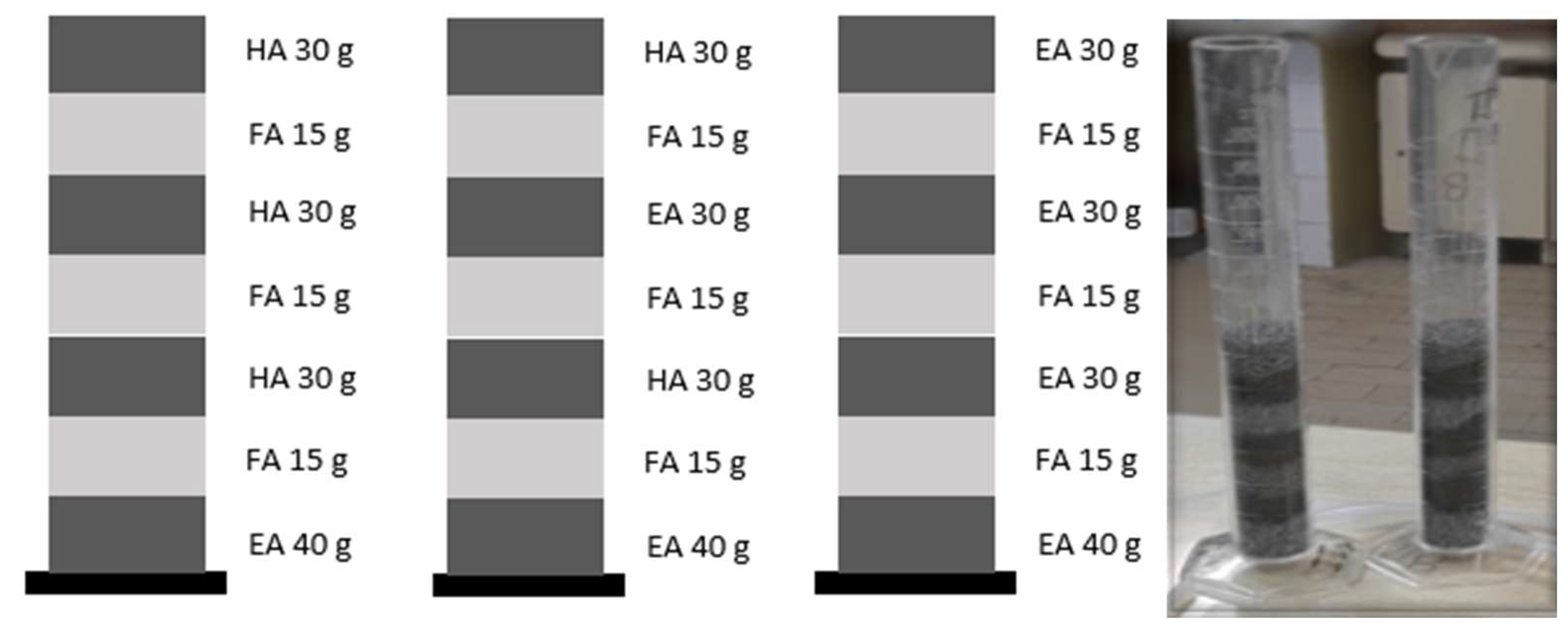
Figure 1. Disposing of waste in the columns.
Metals 15 00888 g001
Figure 2. Configuration of laboratory columns developed for experimental purposes.
Metals 15 00888 g002
Figure 3. The prefabricated channels filled with waste ready for testing.
Metals 15 00888 g003
Figure 4. Equipment ready for testing.
Metals 15 00888 g004
Figure 5. The evolution of arsenic (As) concentration versus volume of contaminated water can be observed in columns IA and IB in the first 14 days of the test.
Metals 15 00888 g005
Figure 6. The evolution of arsenic (As) concentration versus volume of contaminated water can be observed in columns IIA and IIB in the first 14 days of the test.
Metals 15 00888 g006
Figure 7. The evolution of arsenic (As) concentration versus volume of contaminated water can be observed in columns IIIA and IIIB in the first 14 days of the test.
Metals 15 00888 g007
Figure 8. The evolution of arsenic (As) concentration versus volume of contaminated water in columns I, II, and III.
Metals 15 00888 g008
Figure 9. The evolution of arsenic (As) concentration versus volume of contaminated water.
Metals 15 00888 g009
Figure 10. Adsorbent concentration vs. % As removal.
Metals 15 00888 g010
Figure 11. As concentration in by-products (FA and HA) after treatment along the channel.
Metals 15 00888 g011
Table 1. Physico-chemical characteristics of by-products.
FAEAHA
SiO2 (wt %)56.534.213.8
Fe2O3 (wt %)9.50.337.9
MgO (wt %)0.95.71.1
K2O (wt %)2.60.40.3
Al2O3 (wt %)23.912.82.1
CaO (wt %)3.44238.3
SO3 (wt %)2.03.31.14
TiO2(wt %)0.70.60.5
MnO (wt %)-0.33.5
Hg mg/Kg25.516.3
As mg/Kg5910.337.8
Zn mg/Kg90457.5
Cu mg/Kg572.226
Cr mg/Kg83.62749
Pb mg/Kg1619
Ni mg/Kg65.40.424
Cd mg/Kg1.8-0.16
pH10.911.311.0
real density g/cm32.43.03.6
Table 2. Subproducts mass (kg) and As (mg/kg) concentrations in test Columns.
SubproductFAEAHA
Subproducts mass (kg)0.1350.2400.150
AsAsAs
Initial concentration (mg/kg)5910.337.8
Final concentration (mg/kg)1229250.3489.6
Concentration increase (mg/kg)1110240451.8
Mass of As retained (mg)157.957.667.8
Table 3. Water volume (L) and As (µg/L) concentrations in test Microchannels.
As
Volume of contaminated water (L)29.48
Average initial concentration (µg/L)12,472
Average final concentration (µg/L)147
Concentration reduction (%)98.82
Concentration reduction (µg/L)12,325
As mass retention (mg)363.3
Table 4. Subproducts mass (kg) and As (mg/kg) concentrations in tests.
SubproductFAHA
Subproducts mass (kg)15.523.5
AsAs
Initial concentration (mg/kg)591.05
Final concentration (mg/kg)71.467.94
Concentration increase (mg/kg)12.466.89
Mass of As retained (mg))193.13161.92
Disclaimer/Publisher’s Note: The statements, opinions and data contained in all publications are solely those of the individual author(s) and contributor(s) and not of MDPI and/or the editor(s). MDPI and/or the editor(s) disclaim responsibility for any injury to people or property resulting from any ideas, methods, instructions or products referred to in the content.